42
1 Static vs. Velocity Pressure
| Date post: | 03-Jan-2016 |
| Category: |
Documents |
| Upload: | pearl-page |
| View: | 260 times |
| Download: | 1 times |

1
Static vs. Velocity Pressure
2
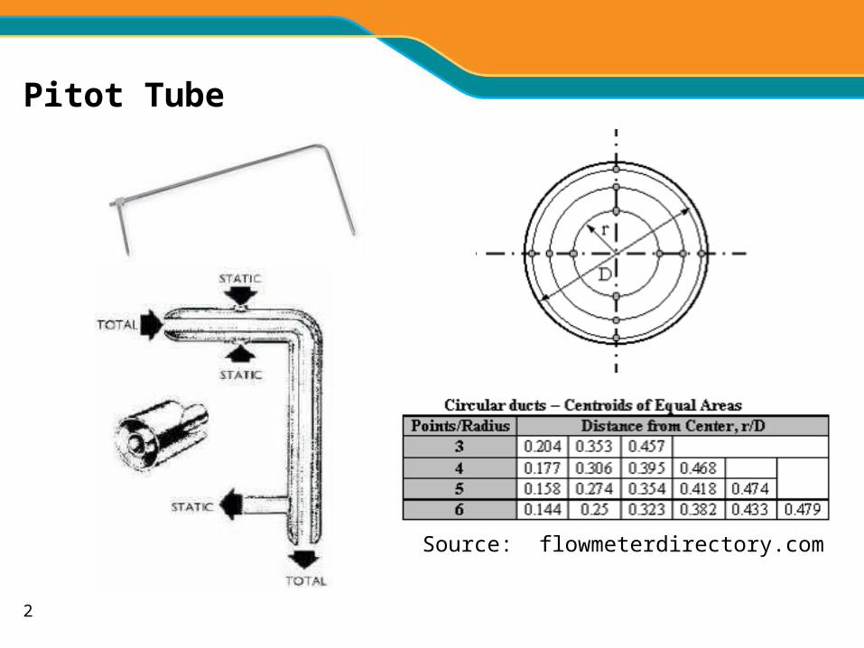
Pitot Tube
Source: flowmeterdirectory.com

3
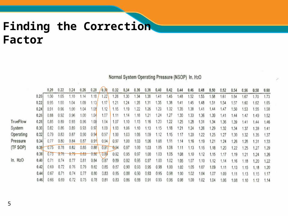
NSOP
.30

4
TFSOP
.36
5
Finding the Correction Factor
6
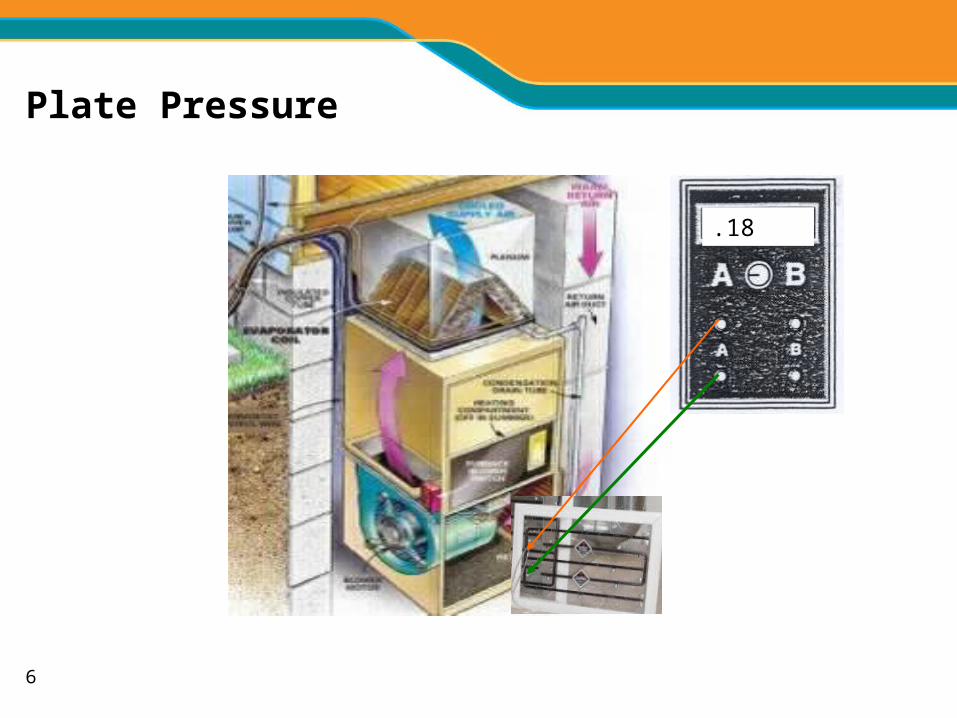
Plate Pressure
.18

7

8
Corrected Flow
• To calculate corrected flow, multiply raw flow x correction factor;
• Raw flow of 769 CFM X .91 = 700 CFM.

9
634 cfm (fan-assist)656 cfm (flow plate)
Return plenum
Elec. Air Cleaner
Supply plenum
64.0 ºF
176.7 208.5 147.0134.9 180.2 149.9101.6 135.3 124.0
Average: 150.9 ºF
21.8 kW Furnace
Flow? 793 cfm (average ΔT=87 ºF)593 cfm (center ΔT=116 ºF)477 cfm (max ΔT=144 ºF)1832 cfm (min ΔT=38 ºF)
ΔT ≈ 109 ºF
11
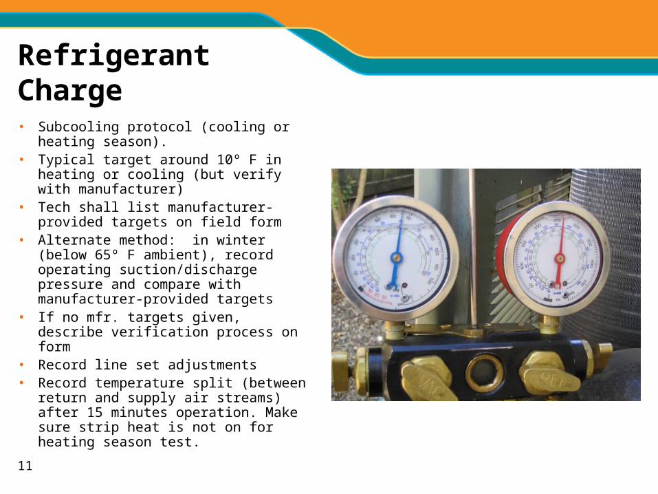
Refrigerant Charge
• Subcooling protocol (cooling or heating season).
• Typical target around 10º F in heating or cooling (but verify with manufacturer)
• Tech shall list manufacturer-provided targets on field form
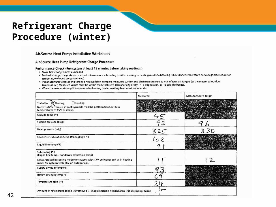
• Alternate method: in winter (below 65º F ambient), record operating suction/discharge pressure and compare with manufacturer-provided targets
• If no mfr. targets given, describe verification process on form
• Record line set adjustments• Record temperature split (between return
and supply air streams) after 15 minutes operation. Make sure strip heat is not on for heating season test.
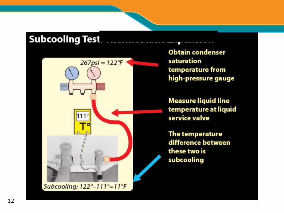
12

13

14
Refrigerant Charge Procedure (summer)
325

15
Winter charge evaluation
• “Winter” defined as outdoor temperature below 65º F.
• Weigh-in for line set adjustment
• Can check subcooling (check in same place as for cooling– on liquid line just before entry into outdoor unit). Only works for systems with TXV on outdoor coil and need to have manufacturer’s target value for comparison.
OR…
• Measure outdoor temperature and discharge/suction operating pressures and compare with mfr’s tables

16
Charge Evaluation(summer and winter)
• Too much subcooling vs. target (more than 3º F over target), remove refrigerant until within 3º F of target
• Not enough subcooling (more than 3º F under target), add refrigerant until within 3º F of target.
• Temperature split: should be at least ½ of outdoor temperature in heating (20º F if 40º F outside) and generally 17-22º F in cooling.

17
Water Source Heat Pumps
• Measure pressure drop across system and calculate GPM
• If GPM in expected range (usually about 1.5 GPM/ton of capacity), measure loop temp. split and compare with mfr’s target value
• Measure air side temp. split and compare with expected values
• If loop temp. split and/or air side split is not at mfr’s expected value(s), measure superheat/subcooling, make adjustments, and retest.

18
Refrigerant Charge Procedure (winter)
19
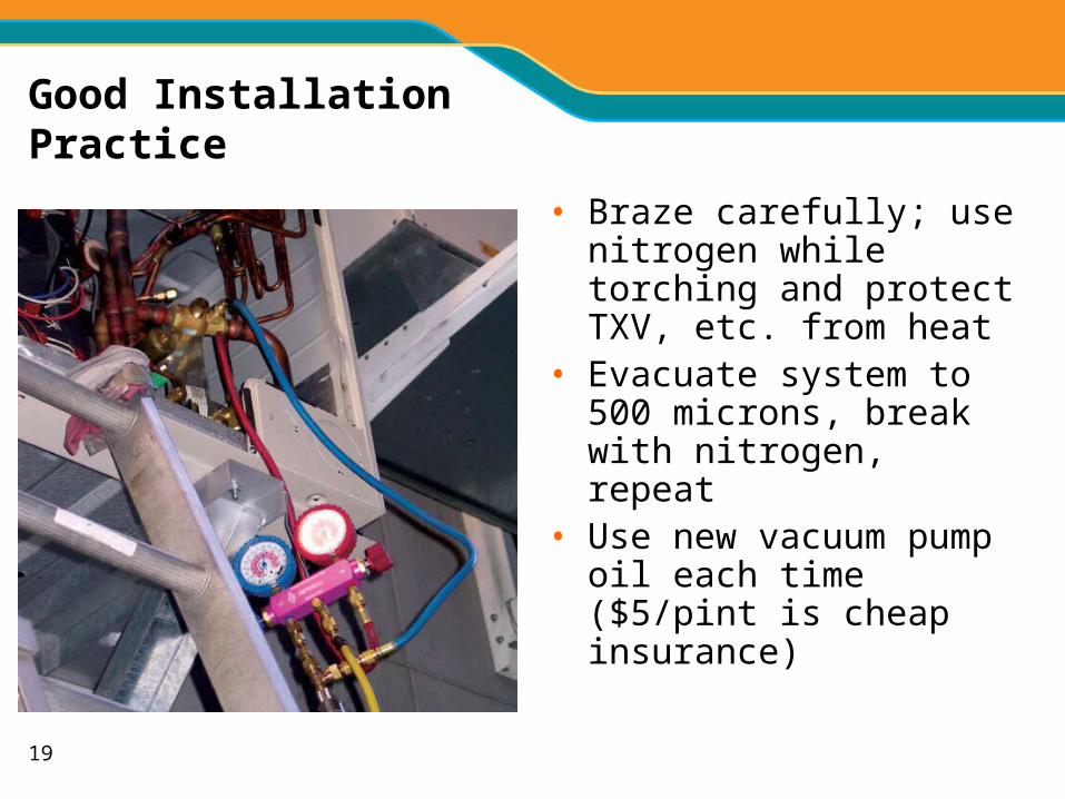
Good Installation Practice
• Braze carefully; use nitrogen while torching and protect TXV, etc. from heat
• Evacuate system to 500 microns, break with nitrogen, repeat
• Use new vacuum pump oil each time ($5/pint is cheap insurance)
20
Calibration
• Check thermocouples and pressure gauges regularly for accuracy
• Ice test for thermocouples
• Saturation test for manifold gauges

21
Heat Pump Controls
• Strip heat
• Compressor
• Discharge air sensor

22
The Big No Nos
• Wiring in strip heat to operate on a Stage 1 heating call
• Not installing an outdoor (lockout) thermostat to limit use of strip heat during mild conditions
• Locking out the compressor at any temp. above 0º F.• Using a discharge temp sensor which brings on strip
heat when it is not needed
23
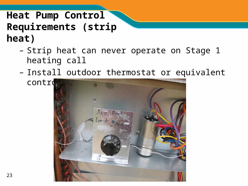
Heat Pump Control Requirements (strip heat)
– Strip heat can never operate on Stage 1 heating call
– Install outdoor thermostat or equivalent control and set at 40°F

24
Outdoor Thermostat– The Basics
Close on fall switch keeps off strip heat until outdoor temp below activation point. Note system can still activate strip heat if there is a call from outdoor unit (defrost) or homeowner switches to emergency heat
Remove this wire when using outdoor t’stat

25
Pay attention to the small print

26
Morning Warm Up - Pre Retrofit
05
10152025303540455055606570
8:00 8:15 8:30 8:45 9:00 9:15 9:30 9:45 10:00
OAT Thermostat Inside Temp
20kw15kW10kW5 kW0 kW
Strip Heat On
Compressor On
Courtesy Proctor Engineering Group

27
Morning Warm Up - Post Retrofit
05
10152025303540455055606570
8:00 8:15 8:30 8:45 9:00 9:15 9:30 9:45 10:00
OAT Thermostat Inside Temp OAT Thermostat Inside Temp
Compressor On
Defrost Cycle
20kW15kW10Kw5 kW0kW
kW
Input
20kw15kW10kW5 kW0 kW
Courtesy Proctor Engineering Group

28
Heat Pump Controls:Compressor Lockout
• Heat pumps provide heat even at low outdoor temperatures
• All manufacturers provide output tables at 5º F (and even lower)
• IPCO requires compressor to operate down to 0º F
• Factory setting for most new thermostats is to never lock out compressor

29
Installer Setup
ENTER INSTALLER SETUP
1. Press the SYSTEM key
2. PRESS and HOLD the two unmarked keys as shown until the display changes
– approximately 5 seconds
30
IPCO Program Settings
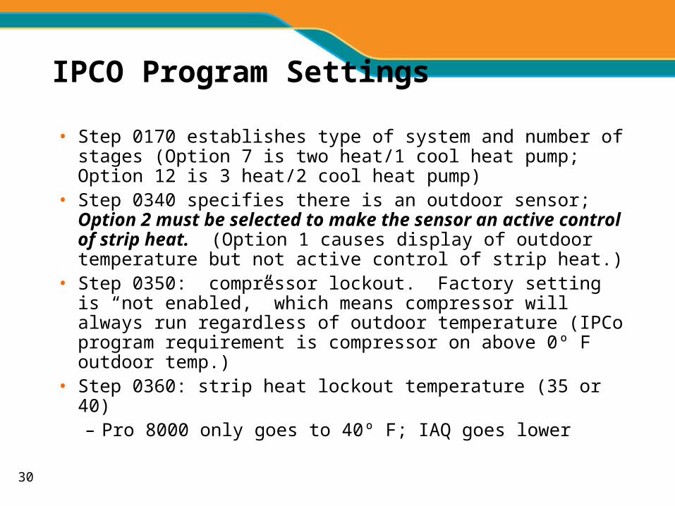
• Step 0170 establishes type of system and number of stages (Option 7 is two heat/1 cool heat pump; Option 12 is 3 heat/2 cool heat pump)
• Step 0340 specifies there is an outdoor sensor; Option 2 must be selected to make the sensor an active control of strip heat. (Option 1 causes display of outdoor temperature but not active control of strip heat.)
• Step 0350: compressor lockout. Factory setting is “not enabled,” which means compressor will always run regardless of outdoor temperature (IPCo program requirement is compressor on above 0º F outdoor temp.)
• Step 0360: strip heat lockout temperature (35 or 40)– Pro 8000 only goes to 40º F; IAQ goes lower

31
Outdoor Sensor
• Needs wires sep. from rest of 24v bundle
• Mount out of sun; best on north side of house up under eave
• Mount to avoid contact with rain/snow
• Check temp display on tstat and compare with measured outdoor temperature; should be within 2% (so within ± 1º F if 50º F outside)

32
Checking Sensor Reading at Thermostat
Should be within 5% (1-2º F) of actual outside temperature
33
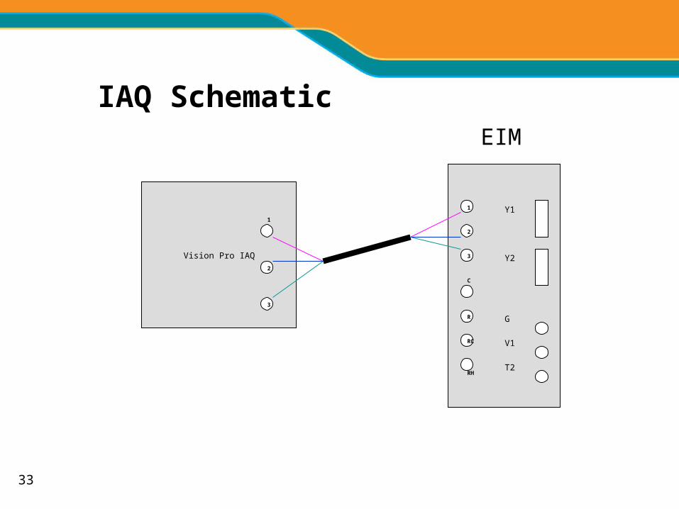
Vision Pro IAQ
Y1
Y2
G
RH
RC
R
2
3
1
C
1
2
3
V1
T2
EIM
IAQ Schematic

34
Differences Between VPro 8000 and IAQ Setup Steps
• The main difference is that the strip heat lockout is in Step 0342 (vs 340). Set at “2” in both cases.
• There are other differences in basic system setup Step numbers (they are similar but not all the same).
• IAQ also has auto-discover feature for communicating fan coils
• Note Trane and Lennox touchscreen stats use very similar programming Steps
35
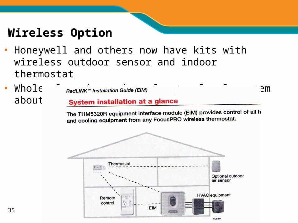
Wireless Option
• Honeywell and others now have kits with wireless outdoor sensor and indoor thermostat
• Wholesale price point of entry-level system about $225.

36
More Heat Pump Controls
• Single-stage compressors: discharge air sensor control not allowed
Typical Heat Cycle
0
2000
4000
6000
8000
10000
12000
12:0
012
:02
12:0
412
:06
12:0
812
:10
12:1
212
:14
12:1
612
:18
12:2
012
:22
12:2
4
Time
Po
we
r, W
atts
compresistfan

37
HP Controls (final spec)
• Set discharge sensor to 85°F for multi-compressor stage systems/zoned systems or install outdoor t-stat if warmer staging temperature used
• Some zoning controls do not accommodate and outdoor sensor/close on fall switch (dial-type); check with manufacturer rep if not sure. If you cannot control strip heat operation above 35º F (except for emergency heat/defrost), this control combination is not allowed in IPCo’s program

38
Installation Worksheet – Page 1

39
Installation Worksheet: Airflow

40
Heat Pump Controls Page

41
Refrigerant Charge Procedure (summer)
325
42
Refrigerant Charge Procedure (winter)

43
Water Source Heat Pump Form


