Page 1
1
Strength Testing of Hybrid Carbon Composites
for Automotive Structures
Michael Capasso Anthony Polo
[email protected] [email protected]
Stephanie Tu
[email protected]
New Jersey Governor’s School of Engineering and Technology 2014
Abstract
Vehicles today require fuel-efficient
and durable designs to compete in the
demanding automotive industry. Hybrid
carbon composites are new and popular
alternatives to the heavy metals used in the
frames of most automobiles.1
Methods of
decreasing the expenses of carbon fiber
usage in cars range from different material
utilization to optimal structuring of fibers at
the production level. Hybrid carbon
composites are already popular for use in
certain accessories in performance
automobiles as well, such as spoilers,
scoops, and hoods.
Carbon fiber, being lightweight and
strong, can be used in such parts because it
keeps the car light and therefore the
efficiency high. Not only is it less expensive
to make, but it is also becoming easier to
produce in larger quantities. Using a
combination of traditional and contemporary
methods, carbon fiber specimens were
created and tested for strength using a
Tensile Test Machine. Five different carbon
fiber configurations were put under load
stress to see which layout was most effective
and would also maintain the strength levels
necessary for safe automobile structures.
1. Introduction
1.1 Composites
A composite material is defined as a
material system consisting of two or more
phases on a macroscopic scale whose
mechanical performance and properties are
designed to be superior to those of the
constituent materials acting independently.
One of these phases is usually
discontinuous, stiffer, and stronger and is
called the reinforcement, whereas the less
stiff and weaker phase is continuous and is
called the matrix.2
A carbon composite is a material in
which carbon fiber strands are the
reinforcement and a polymer resin is
designated as the matrix. The resultant
composite is cured to create an almost
metallic sheet that is incredibly lightweight
and durable. The interlocking pattern in
Page 2
2
which the carbon fibers and polyester are
connected contributes directly to the
strength of the final product, as it creates for
stronger bonds. As viewed in Figure 1, these
composites have nearly endless applications,
as they can be molded into any shape
imaginable. In almost any problem requiring
a lightweight, yet nearly indestructible
solution, carbon composites may be utilized.
The main difficulty with using carbon fiber
structures is that the carbon fibers must be
handmade and therefore consume a
significant amount of time and energy to
produce.
Fig. 1
Raw Carbon Fiber Sheet Infused With Resin
1.2 Applications
With recent developments many
industries, especially the automotive and
recreation industries, are beginning to use
these composites in their products.3 The
automobile industry is always searching for
more cost efficient methods of improving
their products’ attributes to increase
revenue, and carbon composites hold all the
properties necessary for their endeavors.
Carbon composites, made of carbon fibers,
have a resilient and lightweight structure;
the fibers are particularly strong in their
coinciding axis. This could prove to be an
integral part of automobiles of the future and
seeing that this has already been
implemented in certain companies, the
promising future for carbon fibers now may
be the present.
2. Background
2.1 Layout
Carbon fiber is unique in that it is
incredibly lightweight, durable, and strong,
but these specific properties vary according
to the direction in which the fibers are laid
during preparation prior to cooking.4 As
seen in Figure 2, when the fibers are laid all
in the same direction – or unidirectional -
the structure is especially strong in the
direction that the fibers run.
Fig. 2
Unidirectional Layering
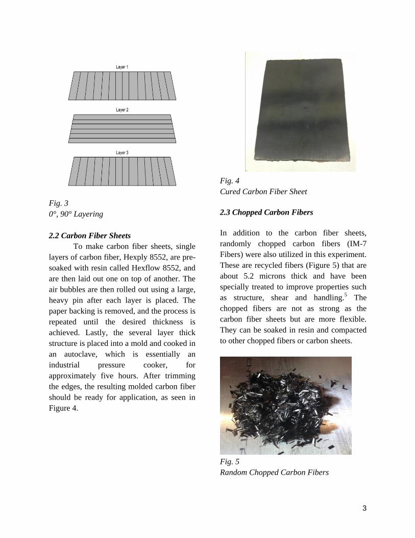
However, when the fibers are laid in
a direction that is perpendicular to the ones
adjacent to it, as seen in Figure 3, the
structure becomes strong in both directions,
but not nearly as strong as a unidirectional
design. This is also known as the 0°, 90°
design.
Page 3
3
Fig. 3
0°, 90° Layering
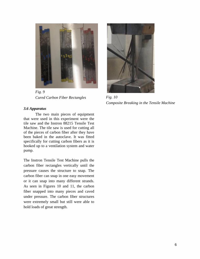
2.2 Carbon Fiber Sheets
To make carbon fiber sheets, single
layers of carbon fiber, Hexply 8552, are pre-
soaked with resin called Hexflow 8552, and
are then laid out one on top of another. The
air bubbles are then rolled out using a large,
heavy pin after each layer is placed. The
paper backing is removed, and the process is
repeated until the desired thickness is
achieved. Lastly, the several layer thick
structure is placed into a mold and cooked in
an autoclave, which is essentially an
industrial pressure cooker, for
approximately five hours. After trimming
the edges, the resulting molded carbon fiber
should be ready for application, as seen in
Figure 4.
Fig. 4
Cured Carbon Fiber Sheet
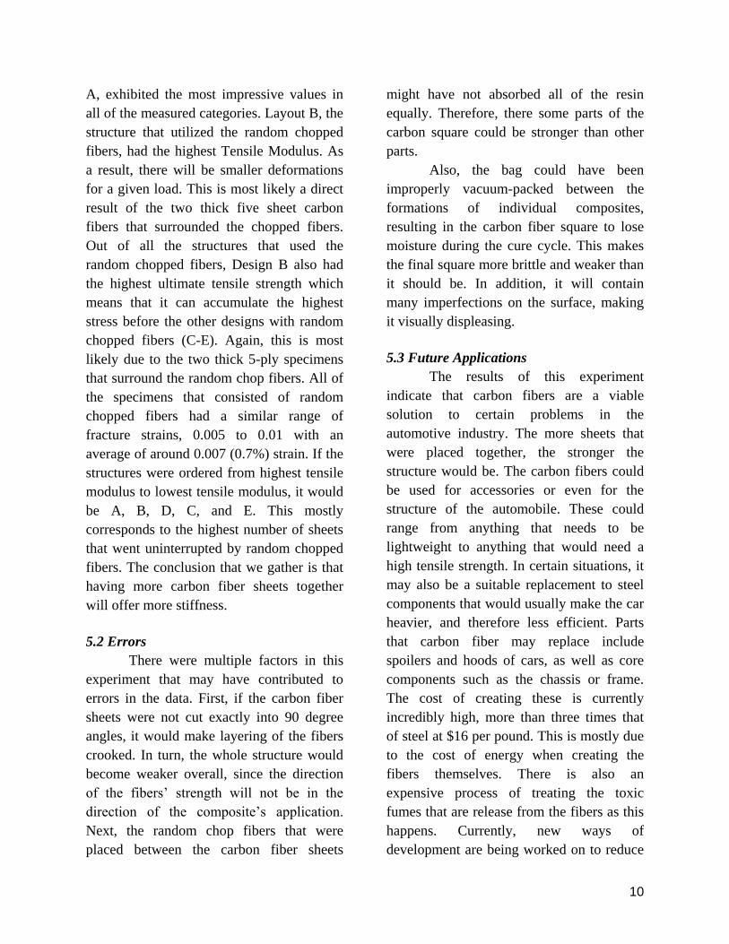
2.3 Chopped Carbon Fibers
In addition to the carbon fiber sheets,
randomly chopped carbon fibers (IM-7
Fibers) were also utilized in this experiment.
These are recycled fibers (Figure 5) that are
about 5.2 microns thick and have been
specially treated to improve properties such
as structure, shear and handling.5 The
chopped fibers are not as strong as the
carbon fiber sheets but are more flexible.
They can be soaked in resin and compacted
to other chopped fibers or carbon sheets.
Fig. 5
Random Chopped Carbon Fibers
Page 4
4
3. Experimental Procedure
3.1 Design
This experiment was designed to test
the strength of carbon fiber structures in
automotive applications. Four different
designs were chosen to test strength
regarding impact and collision forces. Each
design consisted of ten 6 inch by 6 inch
sheets of carbon fiber. Additionally, 20
grams total of various small chopped carbon
fibers were compacted between the sheets of
carbon and everything was held together
with resin. The control group (Design A) for
this experiment is a 6in by 6in carbon fiber
square consisting of 10 unidirectional layers.
Design B is a square consisting of 5
unidirectional (uni) sheets, various fibers,
and 5 uni sheets. Design C is a square that
has the design of 4 uni, various fibers, 2 uni,
various fibers, and 4 uni. Design D consists
of 2 uni, various fibers, 6 uni, various fibers,
and 2 uni. Finally, Design E is a layout of 2
uni, various fibers, 3 uni, various fibers, 3
uni, various fibers, and 2 uni. Each design
was specially created in order to test what
kind of pressure it could withstand.
3.2 Preparation
In order to perform this experiment,
the 6 inch by 6 inch square sheets must first
be cut from the roll of carbon fiber which is
pre-soaked with resin. The squares must be
cut at precise 90 degree angles in order for
the structure to have maximum strength. If
the sheets are cut crookedly and placed one
on top of another, they won’t adhere
properly to one another. After the squares
have been cut, they are prepared for
layering; each square must be clean of all
debris or dust stuck to it, otherwise, the
squares will not adhere flush to one another.
As a result, the structure would be weaker
than the optimal strength. Next, the squares
will be stacked on top of each other, and the
quantity is determined by the number of
layers required by the specific design. The
carbon fiber sheets are fastened to paper on
one side which makes for easier transport.
The adhesive side of the stacked sheets are
placed together and rolled with a 25 pound
steel cylinder in order to eliminate any
potential air bubbles. Once the squares are
prepared, various small carbon fibers are
obtained for each layer of fiber sheets. These
fibers will be sprinkled on top of the layer of
carbon fiber sheets as designated in the
design. Resin is then poured on top of the
fibers to bind the small fibers to the sheets.
The amount of resin must be adequate to
coat the entire layer, but if there is excess, a
vacuum later in the process will pull all the
extra resin out of the structure. After the
square is complete, it must be prepared for
the autoclave.
3.3 Vacuum
The carbon fiber compilation must
first be vacuum packed before it can be
placed into the autoclave. The process
begins with the packing down of our carbon
fiber matrix by placing it between two metal
sheets after surrounding it with cork to
prevent resin from leaking. The metal sheets
must be fully covered with sheets of blue
plastic in order to prevent resin from
sticking to the metal. After, the carbon fiber
compilation can be placed between the
sheets of metal. Breather fabric, similar to a
sheet of cotton, must be placed between the
metal sheets to let the resin have something
to soak into. Once these steps are completed,
the carbon fibers are surrounded by cork,
which also soaks up the excess resin. Once
the cork is laid out, the two metal sheets can
be placed together. Sealant tape surrounds
the metal sheets. Lastly, the entire system is
wrapped in a vacuum bag and the air is
removed from the system using a vacuum
pump. This step is incredibly important, for
if the seal breaks, moisture leaves the resin
Page 5
5
coating on the fibers. This can occur
relatively often during the production of the
composites and when this occurs the bag
must be replaced and new sealant tape must
be applied. The whole system, as referenced
in Figures 6 and 7, is placed in the autoclave
and will cure for five hours.
Fig. 6
Carbon Fiber Preparation6
Fig. 7
Experimental Layout
3.4 Autoclave
There is a specific cycle of cooking
that the carbon fiber is exposed to
throughout these five hours, as seen in
Figure 8. First, the autoclave heats to
approximately 225°F. It remains that way
for just over 2.5 hours. At the end of these
two and a half hours, pressure amounting to
about 100 PSI is applied to the entire
system. As this pressure is applied, the heat
raises to about 350°F within the autoclave.
Again, it remains this way for another 2.5
hours, and the process is complete.
Fig. 8
Autoclave Curing Process7
3.5 Finish
After the cooking system is removed
from the autoclave, the vacuum seal is
released and the carbon fiber sheet is
completed. The excess resin would likely
bind to the cork that surrounded the carbon
fiber matrix during cooking, so it would
need to be broken off, and the edge had to
be trimmed with the tile saw. After this
process, the finished product is ready to be
cut to the specific shape for use in the
desired products. The baked squares are now
cut into 6 inch by 0.25 inch rectangles as in
Figure 9. The newly cut rectangles are
measured in width and thickness and the
data is multiplied to find the area of the
cross section. Measured in millimeters
squared, the cross section area is inputted
into the computer for use in the Instron
88215 Tensile Test Machine. The strength
of these carbon rectangles is tested using the
machine to simulate the forces on an
automobile structure during collisions as
well as general use.
Page 6
6
Fig. 9
Cured Carbon Fiber Rectangles
3.6 Apparatus
The two main pieces of equipment
that were used in this experiment were the
tile saw and the Instron 88215 Tensile Test
Machine. The tile saw is used for cutting all
of the pieces of carbon fiber after they have
been baked in the autoclave. It was fitted
specifically for cutting carbon fibers as it is
hooked up to a ventilation system and water
pump.
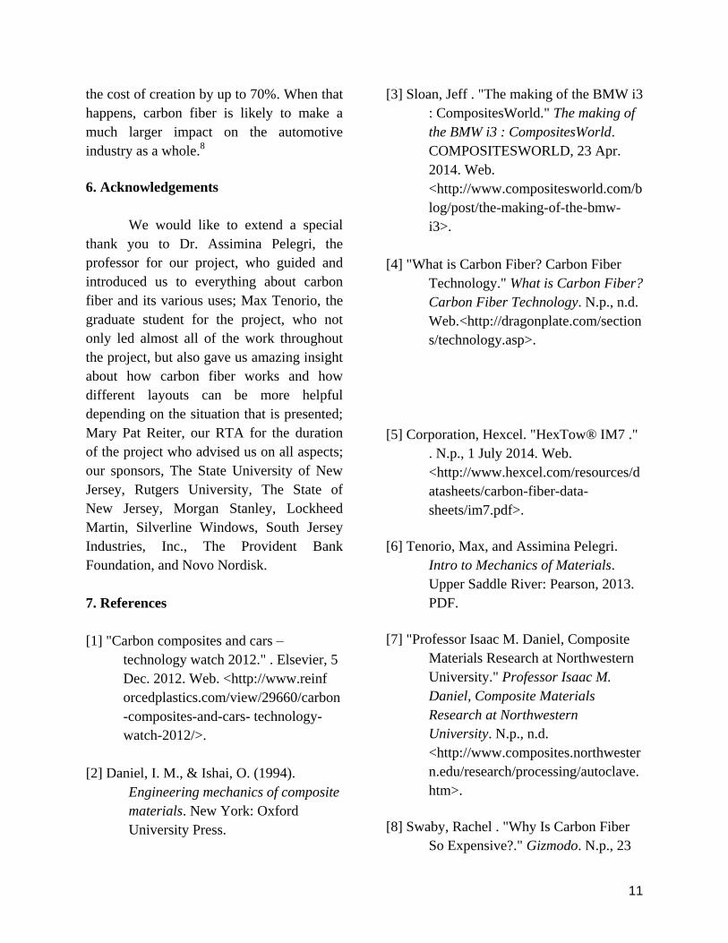
The Instron Tensile Test Machine pulls the
carbon fiber rectangles vertically until the
pressure causes the structure to snap. The
carbon fiber can snap in one easy movement
or it can snap into many different strands.
As seen in Figures 10 and 11, the carbon
fiber snapped into many pieces and caved
under pressure. The carbon fiber structures
were extremely small but still were able to
hold loads of great strength.
Fig. 10
Composite Breaking in the Tensile Machine
Page 7
7
Fig. 11
Broken Carbon Fiber Structures
4. Results and Discussion
4.1 Data
Rectangle
Number
Width
(mm)
Thickness
(mm)
Cross
Sectional Area
(mm²)
A 1 4.55 1.57 7.144
2 4.91 1.58 7.758
3 5.73 1.53 8.767
4 5.58 1.55 8.649
5 5.91 1.53 9.042
B 1 6.24 1.93 12.043
2 6.22 2.32 14.430
3 6.31 2.06 12.999
4 6.26 2.03 12.708
5 6.37 2.25 14.333
C 1 5.68 2.34 13.291
2 6.24 2.24 13.978
3 5.95 2.42 14.399
4 6.07 2.34 14.204
5 6.03 2.46 14.834
D 1 6.13 2.08 12.750
2 6.08 2.1 12.768
3 6.06 2.21 13.393
4 6.15 2.25 13.838
5 6.17 2.38 14.685
Page 8
8
E 1 6.45 2.36 15.222
2 6.76 2.36 15.954
3 5.94 2.44 14.494
4 6.37 2.46 15.670
5 6.31 2.48 15.649
Fig. 12
Carbon Fiber Rectangle Measurements
4.2 Calculations
The above information was obtained
using calipers by measuring the width and
thickness of each sample, and multiplying
them together to receive the cross-sectional
area. After testing, the cross sectional area
of each structure, the amount of force they
withstood, and the distance they stretched
were taken and plugged into the stress and
strain equations. This would allow for
calculations of the overall strength of the
sample without any bias based on the size of
the individual sample.
4.3 Results
Young's
Modulus (GPa)
Ultimate
Tensile
Strength
(GPa)
Fracture
Strain
A1 144.14 1.59 0.009
A2 164.47 2.13 0.012
A3 151.19 1.93 0.012
A4 154.9 1.93 0.012
A5 153.63 1.93 0.012
153.666 1.902 0.0114
B1 124.98 1.23 0.009
B2 119.31 0.84 0.006
B3 191.02 1.01 0.005
B4 129.87 1.15 0.008
B5 115.84 1.12 0.008
136.204 1.07 0.0072
C1 125.29 0.77 0.006
C2 105.13 0.86 0.008
C3 106.78 0.98 0.009
C4 114.81 1.1 0.008
C5 102.65 0.79 0.007
110.932 0.9 0.0076
D1 150.81 0.861 0.005
D2 128.48 1.142 0.008
D3 132.55 0.654 0.0021
D4 107.07 0.558 0.005
D5 113.2 0.57 0.005
126.422 0.757 0.00502
E1 111.39 0.667 0.006
E2 106.11 0.82 0.007
E3 98.786 0.69 0.008
E4 113.3 0.72 0.009
E5 99.178 0.58 0.006
105.7528 0.6954 0.0072
A 153.66 1.902 0.0114
B 136.204 1.07 0.0072
C 110.932 0.9 0.0076
D 126.422 0.757 0.00502
E 105.4528 0.6954 0.0072
Fig. 13
Stress and Strain Data
Page 9
9
As stated before, the stress and strain
that was calculated would allow for the
actual strength of the layout without any
bias based on variations in size. To do this,
the stress and strain of each sample were
taken and plugged into the Young’s
Modulus equation. After doing this, it was
determined that Design A, the control, had
the highest average ultimate tensile strength,
fracture strain, and young’s modulus, while
design E had the lowest for all three. This
shows that separating the layers of carbon
fiber and putting sections of random
chopped fibers and resin in between
weakens the overall tensile strength of the
system weaker. However doing this can
increase the volume of the final product, so
if only a certain amount of tensile strength is
needed for an application, more can be
received for a lower price, with the cost
being in the lower strength value.
4.4 Discussion
Testing of the composites’ strength
was done through tensile strength testing, so
samples withstood stress across one axis.
The fiber sheets used in experimentation
were therefore all oriented unidirectionally,
to find the maximum strength of the
material. All the materials tested had 10
sheets of resin-infused fibers and 20 grams
of randomly chopped fibers to implement
consistency, while the structure of the layout
was variable. This method of testing reveals
the most effective structure to implement
recycled fibers in larger industries, such as
automobiles.
To compare the strengths of the
rectangles, the Ultimate Tensile Strength
(UTS) of each rectangle was found. The
cross sectional area of the rectangles had to
be utilized in order to accurately compare
strength values. When the carbon fiber
square was cut into significantly smaller
rectangles, they were not all the same
precise dimensions. This would affect the
strength needed to break the different
rectangles, so the data received was plugged
into a stress formula, in order for the cross
sectional area of each strip was taken into
account. The capability of the material to
withstand stress based on the amount of
material was found through the load and
area of the rectangles.
Fig. 14
Stress vs. Strain
5. Conclusions
5.1 Evaluation
The data revealed that the strength of
the carbon composite depended on the
separation of the fiber sheet in the layering
of the materials, as the layouts with the
lesser amount of dispersion between long-
stranded, non-recycled sheets of fiber had
the higher UTS values. The control, layout
Page 10
10
A, exhibited the most impressive values in
all of the measured categories. Layout B, the
structure that utilized the random chopped
fibers, had the highest Tensile Modulus. As
a result, there will be smaller deformations
for a given load. This is most likely a direct
result of the two thick five sheet carbon
fibers that surrounded the chopped fibers.
Out of all the structures that used the
random chopped fibers, Design B also had
the highest ultimate tensile strength which
means that it can accumulate the highest
stress before the other designs with random
chopped fibers (C-E). Again, this is most
likely due to the two thick 5-ply specimens
that surround the random chop fibers. All of
the specimens that consisted of random
chopped fibers had a similar range of
fracture strains, 0.005 to 0.01 with an
average of around 0.007 (0.7%) strain. If the
structures were ordered from highest tensile
modulus to lowest tensile modulus, it would
be A, B, D, C, and E. This mostly
corresponds to the highest number of sheets
that went uninterrupted by random chopped
fibers. The conclusion that we gather is that
having more carbon fiber sheets together
will offer more stiffness.
5.2 Errors
There were multiple factors in this
experiment that may have contributed to
errors in the data. First, if the carbon fiber
sheets were not cut exactly into 90 degree
angles, it would make layering of the fibers
crooked. In turn, the whole structure would
become weaker overall, since the direction
of the fibers’ strength will not be in the
direction of the composite’s application.
Next, the random chop fibers that were
placed between the carbon fiber sheets
might have not absorbed all of the resin
equally. Therefore, there some parts of the
carbon square could be stronger than other
parts.
Also, the bag could have been
improperly vacuum-packed between the
formations of individual composites,
resulting in the carbon fiber square to lose
moisture during the cure cycle. This makes
the final square more brittle and weaker than
it should be. In addition, it will contain
many imperfections on the surface, making
it visually displeasing.
5.3 Future Applications
The results of this experiment
indicate that carbon fibers are a viable
solution to certain problems in the
automotive industry. The more sheets that
were placed together, the stronger the
structure would be. The carbon fibers could
be used for accessories or even for the
structure of the automobile. These could
range from anything that needs to be
lightweight to anything that would need a
high tensile strength. In certain situations, it
may also be a suitable replacement to steel
components that would usually make the car
heavier, and therefore less efficient. Parts
that carbon fiber may replace include
spoilers and hoods of cars, as well as core
components such as the chassis or frame.
The cost of creating these is currently
incredibly high, more than three times that
of steel at $16 per pound. This is mostly due
to the cost of energy when creating the
fibers themselves. There is also an
expensive process of treating the toxic
fumes that are release from the fibers as this
happens. Currently, new ways of
development are being worked on to reduce
Page 11
11
the cost of creation by up to 70%. When that
happens, carbon fiber is likely to make a
much larger impact on the automotive
industry as a whole.8
6. Acknowledgements
We would like to extend a special
thank you to Dr. Assimina Pelegri, the
professor for our project, who guided and
introduced us to everything about carbon
fiber and its various uses; Max Tenorio, the
graduate student for the project, who not
only led almost all of the work throughout
the project, but also gave us amazing insight
about how carbon fiber works and how
different layouts can be more helpful
depending on the situation that is presented;
Mary Pat Reiter, our RTA for the duration
of the project who advised us on all aspects;
our sponsors, The State University of New
Jersey, Rutgers University, The State of
New Jersey, Morgan Stanley, Lockheed
Martin, Silverline Windows, South Jersey
Industries, Inc., The Provident Bank
Foundation, and Novo Nordisk.
7. References
[1] "Carbon composites and cars –
technology watch 2012." . Elsevier, 5
Dec. 2012. Web. <http://www.reinf
orcedplastics.com/view/29660/carbon
-composites-and-cars- technology-
watch-2012/>.
[2] Daniel, I. M., & Ishai, O. (1994).
Engineering mechanics of composite
materials. New York: Oxford
University Press.
[3] Sloan, Jeff . "The making of the BMW i3
: CompositesWorld." The making of
the BMW i3 : CompositesWorld.
COMPOSITESWORLD, 23 Apr.
2014. Web.
<http://www.compositesworld.com/b
log/post/the-making-of-the-bmw-
i3>.
[4] "What is Carbon Fiber? Carbon Fiber
Technology." What is Carbon Fiber?
Carbon Fiber Technology. N.p., n.d.
Web.<http://dragonplate.com/section
s/technology.asp>.
[5] Corporation, Hexcel. "HexTow® IM7 ."
. N.p., 1 July 2014. Web.
<http://www.hexcel.com/resources/d
atasheets/carbon-fiber-data-
sheets/im7.pdf>.
[6] Tenorio, Max, and Assimina Pelegri.
Intro to Mechanics of Materials.
Upper Saddle River: Pearson, 2013.
PDF.
[7] "Professor Isaac M. Daniel, Composite
Materials Research at Northwestern
University." Professor Isaac M.
Daniel, Composite Materials
Research at Northwestern
University. N.p., n.d.
<http://www.composites.northwester
n.edu/research/processing/autoclave.
htm>.
[8] Swaby, Rachel . "Why Is Carbon Fiber
So Expensive?." Gizmodo. N.p., 23
Page 12
12
Sept. 2011. Web.
<http://gizmodo.com/5843276/why-
is-carbon-fiber-so-expensive>.