Page 1
BTAS-16K – Instruction Manual K1.01
Page 1 of 85
TABLE OF CONTENTS
1. System Overview ................................................................................................................ 6
1.1 Description ................................................................................................................................................. 6
1.2 Specifications .............................................................................................................................................. 9
1.3 Customer supplied items: ........................................................................................................................ 10
1.4 Operating Overview ................................................................................................................................ 11
2. Condensed Operating Procedure .................................................................................... 16
2.1 Introduction ............................................................................................................................................. 16
2.2 Operational Steps ..................................................................................................................................... 16
3. Initial Setup ........................................................................................................................ 19
3.1 Connections .............................................................................................................................................. 19
3.2 System Test ............................................................................................................................................... 26
3.3 Tests with the Cell Simulator .................................................................................................................. 29
4. Databases .......................................................................................................................... 31
4.1 Navigation ................................................................................................................................................. 31
4.2 Batteries .................................................................................................................................................... 31
4.3 Customers ................................................................................................................................................. 34
4.4 Operators List .......................................................................................................................................... 35
4.5 Add Customer Batteries .......................................................................................................................... 35
4.6 Find Customer Batteries ......................................................................................................................... 36
5. Work Orders ...................................................................................................................... 37
5.1 Entering (creating) Work Orders........................................................................................................... 37
5.2 Viewing and Editing Work Orders ........................................................................................................ 38
5.3 Closing Work Orders .............................................................................................................................. 38
5.4 Deleting a Work Order............................................................................................................................ 38
5.5 Selecting/deselecting the Work Order.................................................................................................... 39
6. Data Acquisition (to take battery readings) ..................................................................... 42
6.1 Connecting a Nickel-Cadmium Battery ................................................................................................. 42
6.2 Testing the connection ............................................................................................................................. 43
6.3 Connecting a Battery with no blocks or cell terminals ......................................................................... 46
6.4 Programming the Test ............................................................................................................................. 48
6.5 Recording the Test Data .......................................................................................................................... 48
6.6 Sample Screens......................................................................................................................................... 49
6.7 Stopping the Test ..................................................................................................................................... 51
6.8 Resuming the Test .................................................................................................................................... 51
Page 2
BTAS-16K – Instruction Manual K1.01
Page 2 of 85
6.9 Viewing Real Time Graphical Results (Main Screen) .......................................................................... 52
6.10 Viewing Graphical Results ...................................................................................................................... 53
6.11 Viewing Numerical Results ..................................................................................................................... 56
6.12 Printing results ......................................................................................................................................... 58
7. Charger-Analyzer Monitoring and Control ...................................................................... 59
7.1 Identification of Charger-Analyzers ...................................................................................................... 59
7.2 Intelligent Charger-Analyzers (ICA) ..................................................................................................... 60
7.3 Modified Charger-Analyzers .................................................................................................................. 60
8. Water Level ........................................................................................................................ 62
8.1 Manual ...................................................................................................................................................... 62
8.2 Automatic ................................................................................................................................................. 62
9. Calibration ......................................................................................................................... 63
10. Verification of Performance .............................................................................................. 63
10.1 Cell Simulator .......................................................................................................................................... 63
10.2 External Measurements .......................................................................................................................... 66
11. Tools .................................................................................................................................. 67
11.1 Edit Custom Test Settings ....................................................................................................................... 67
11.2 Setup Combination Tests ........................................................................................................................ 68
11.3 Advanced Test Settings ........................................................................................................................... 69
11.4 Technicians ............................................................................................................................................... 70
12. Installation ......................................................................................................................... 71
12.1 Power (mains): ......................................................................................................................................... 71
12.2 Computer .................................................................................................................................................. 71
12.3 Connections .............................................................................................................................................. 71
12.4 Test ............................................................................................................................................................ 71
12.5 System Installation Pictures .................................................................................................................... 71
13. System Maintenance ......................................................................................................... 74
13.1 Data Files .................................................................................................................................................. 74
13.2 Data File Backup ...................................................................................................................................... 74
13.3 Data File Restore ...................................................................................................................................... 74
13.4 Viewing Data Files ................................................................................................................................... 74
13.5 Software Location and Updates .............................................................................................................. 74
14. Troubleshooting ................................................................................................................ 75
14.1 List of common operational issues.......................................................................................................... 75
15. Parts List ............................................................................................................................ 77
Page 3
BTAS-16K – Instruction Manual K1.01
Page 3 of 85
15.1 Data Interface – P/N 9895516003 ........................................................................................................... 77
15.2 Data Hub – P/N 9895516001 (optional) .................................................................................................. 77
15.3 C-Scan – P/N 9895202001 ........................................................................................................................ 77
15.4 Cell Simulator – P/N 9895202301 ........................................................................................................... 77
15.5 20 Cell Cable with Clips (large) – P/N 9895202L20 .............................................................................. 78
15.6 External Shunt - P/N 9895202803 (Charger-Analyzer dependent) ..................................................... 78
15.7 Four Battery Cable – P/N 9895202804 (optional) ................................................................................. 78
15.8 20 Cell Cable with Clips – P/N 9895202M20 ......................................................................................... 78
15.9 21 Cell Cable with Clips – P/N 9895202L21 .......................................................................................... 78
15.10 2x11 Cell Cable with Universal Clips – P/N 9895202D11 (optional) ................................................... 79
15.11 3x7 Cell Cable with Universal Clips – P/N 9895202307 (optional) ...................................................... 79
15.12 Data Cable 6 (6 conductor cable with telephone modular plugs; 12 ft) – P/N 6079M0D612 ............ 79
15.13 DB9 Data Cable 9 (9 conductor cable with DB9 plugs; 6 ft) – P/N 6079DB9MF6 ............................. 79
15.14 Crown for SAFT 20 Cell Batteries “Universal” Configuration) – P/N 9895203C01.......................... 79
15.15 Crown for SAFT 5317, 21 Cell Batteries – P/N 9895203C02 ............................................................... 79
15.16 Crown for SAFT 4579, 20 Cell Batteries – P/N 9895203C03 ............................................................... 79
15.17 Crown for SAFT 276CH, 19 Cell Batteries – P/N 9895203C05 ........................................................... 80
16. GLOSSARY ........................................................................................................................ 81
17. DISCLAIMER ...................................................................................................................... 83
17.1 Qualified Personnel ................................................................................................................................. 83
17.2 JFM Engineering’s responsibility .......................................................................................................... 83
17.3 User’s Responsibility ............................................................................................................................... 83
18. REVISION INDEX ............................................................................................................... 84
19. Notes .................................................................................................................................. 85
Page 4
BTAS-16K – Instruction Manual K1.01
Page 4 of 85
TABLE OF FIGURES
Figure 1 – Comm Ports Screen .............................................................................................................................12 Figure 2 - Main Screen .........................................................................................................................................13 Figure 3 – Typical System Configuration for two Charger-Analyzers and four batteries ....................................19 Figure 4 - Data Interface Front Panel ...................................................................................................................20 Figure 5 - Data Interface Rear Panel ....................................................................................................................20 Figure 6 - Data Interface Connections ..................................................................................................................20 Figure 7 – Data/Control Hub ................................................................................................................................21 Figure 8 - C-Scan Rear Panel ...............................................................................................................................22 Figure 9 - C-Scan Connections .............................................................................................................................22 Figure 10 - C-Scan Front Panel ............................................................................................................................23 Figure 11 – Data/Control Hub ..............................................................................................................................24 Figure 12 - Data Hub Label ..................................................................................................................................24 Figure 13 - Data Hub Connection for cascading ..................................................................................................24 Figure 14 – SMC Rear Panel Connections ...........................................................................................................25 Figure 15 - Control Program Main Screen ...........................................................................................................26 Figure 16 – Comm Ports .......................................................................................................................................27 Figure 17 - Main Screen, Showing a C-Scan available as Terminal #1................................................................27 Figure 18 - Main Screen, Showing a Connected Battery ......................................................................................28 Figure 19 - Cells Simulator Rear Panel ................................................................................................................29 Figure 20 - Cells Simulator Front Panel ...............................................................................................................29 Figure 21 – 24 Cells Simulation pattern with “as Received” test .........................................................................30 Figure 22 - Numerical results from the Cells Simulator .......................................................................................30 Figure 23 – Blank Screen for a new Battery entry ................................................................................................31 Figure 24 – Sample Battery Model and Full Charge 6 Test Parameters ...............................................................32 Figure 25 - Sample Battery Model and 14 hour Charge Test Parameters .............................................................32 Figure 26 - Sample Battery Model and six hour Charge Test Parameters ............................................................33 Figure 27 - Screen for the entry of Customer Information ...................................................................................34 Figure 28 - Screen to enter/edit the names of the system operators ......................................................................35 Figure 29 – View/Edit/Add Customer Battery Screen..........................................................................................35 Figure 30 - Find Customer Battery Screen ...........................................................................................................36 Figure 31 - Screen to enter information into a new Work Order ..........................................................................37 Figure 32 - Screen to select Work Orders .............................................................................................................39 Figure 33 – Work Order assigned on DT #1 ........................................................................................................39 Figure 34 – Two Work Orders in the same C-Scan ..............................................................................................40 Figure 35 - Data Terminals #1 (Master) and #2(Slave) are associated with Charger-Analyzer #1 ......................41 Figure 36 - Two C-Scan with one Charger-Analyzer ...........................................................................................41 Figure 37 - Screen showing information on cables detected ................................................................................42 Figure 38 - Main Screen showing information from various Data Terminals ......................................................43 Figure 39 - Common lead disconnected ...............................................................................................................44 Figure 40 – Cells 1-4 connected ...........................................................................................................................44 Figure 41 – Cells 1-8 connected with #7 and #8 reversed ....................................................................................45 Figure 42 – Cells 1-16 connected with #14 connected to #15 ..............................................................................45 Figure 43 – Four Battery Cable ............................................................................................................................46 Figure 44 – SLA Battery with no accessible block terminals ...............................................................................46 Figure 45 – Nickel-Cadmium Battery with no accessible cell terminals ..............................................................46 Figure 46 - Screen showing information on cables detected ................................................................................46 Figure 47 - Screen showing information on two batteries connected ...................................................................47 Figure 48 – SLA Battery with accessible blocks ..................................................................................................47 Figure 49 - Recording test data .............................................................................................................................48 Figure 50 - Battery cells with colors for “AS RECEIVED” .................................................................................49 Figure 51 - Cells voltages of a battery at the beginning of “CHARGE” ..............................................................49 Figure 52 - Battery shown further along in “CHARGE” ......................................................................................50 Figure 53 - Battery nearing the end of “CHARGE” (higher cell voltages) .........................................................50
Page 5
BTAS-16K – Instruction Manual K1.01
Page 5 of 85
Figure 54 - Screen showing bar colors for the cells of a battery that failed "Capacity" .......................................51 Figure 55 - Screen showing battery voltage vs. time. Note the color change as the battery fails capacity ..........52 Figure 56 - Screen showing a cell voltage vs. time during capacity testing .........................................................52 Figure 57 - Graphical Comparison Screen; Battery Voltage and Cell Voltages ...................................................53 Figure 58 - Comparison Screen; Charge Voltage and Cell Voltages ....................................................................54 Figure 59 - Comparison Screen; Charge Voltage and Charge Current .................................................................54 Figure 60 - Charge Voltage with Cell Voltages....................................................................................................55 Figure 61 – Cell Voltages and individual Cell with voltage drop .........................................................................55 Figure 62 – Work Order Log ................................................................................................................................56 Figure 63 – Battery History Report ......................................................................................................................57 Figure 64 – Cell Data ............................................................................................................................................57 Figure 65 – Work Order Summary .......................................................................................................................58 Figure 66 – Print Button .......................................................................................................................................58 Figure 67 – Charger Types and Status ..................................................................................................................59 Figure 68 – Charger Types and Status ..................................................................................................................59 Figure 69 – Rear Panel Connections.....................................................................................................................60 Figure 70 - C-Scan Rear Panel .............................................................................................................................60 Figure 71 – Control and Shunt connectors on the Charger-Analyzer (CCA) .......................................................61 Figure 72 – Main Screen with Water Level sub Screen .......................................................................................62 Figure 73 - Cells simulation for a 24 Cells ...........................................................................................................63 Figure 74 - Cells simulation for two 11 cell batteries ...........................................................................................64 Figure 75 - Cells simulation for one 20 cell battery .............................................................................................64 Figure 76 - Cells simulation for one 21 cell battery .............................................................................................65 Figure 77 - Cable Code Switch (#1 shown) ..........................................................................................................65 Figure 78 - Cell Simulator Front Panel Switches .................................................................................................66 Figure 79 - Screen to edit custom tests .................................................................................................................67 Figure 80 - Screen to edit custom tests .................................................................................................................68 Figure 81 - Advanced Test Settings ......................................................................................................................70 Figure 82 - Screen to enter/edit the names of the system operators ......................................................................70 Figure 83 – Data Interface and C-Scan .................................................................................................................71 Figure 84 – Cell Simulator and C-Scan ................................................................................................................72 Figure 85 – Temp-Plate and C-Scan .....................................................................................................................72 Figure 86 – Charger-Analyzer, Data Interface, C-Scan and Temp-Plate..............................................................73
Page 6
BTAS-16K – Instruction Manual K1.01
Page 6 of 85
1. System Overview
1.1 Description
1.1.1. Introduction:
Note: The BTAS-16K is a complete new version of the BTAS16 that has been
in operation since 2001. It is characterized by new features, faster operation,
modern screens and a wider utilization of Windows tools.
The BTAS-16K is a system designed to automate the measurement and
analysis of battery parameters as encountered in the process of the testing
and certification of aircraft Nickel-Cadmium batteries. Note: Applicable also
to Lead-Acid batteries.
Proper servicing of Nickel-Cadmium aircraft batteries requires that each of
the cells be monitored throughout the charge and discharge cycles, not just
the battery terminal voltage. Due to the large number of cells, typically 20,
this is a laborious and error prone task, so much that it is currently reduced to
a practical minimum of readings.
Although this minimum of test data marginally satisfies certification
requirements, it does not provide the time detailed information needed to
determine the “true” condition of the cells. Lack of continuous cell voltage
measurements prevents a better assessment of the condition of the battery
and also prevents a better prediction of the future performance of the battery.
The continuous measurements provided by the BTAS16 make it possible to
determine, well in advance, the condition of the battery thus providing
opportunities to save testing time.
Measurements are not limited to cell voltages. The system measures also the
temperature of the battery as well as the charge/discharge current, thus
providing a more complete picture of the test being performed.
Cell readings also become more accurate because they are all performed at
the same time, and are conveniently stored with a time stamp, which
provides an accurate voltage vs. time performance indication.
In addition, the system provides full monitoring and control of new
Intelligent Charger-Analyzers SupersederXG, SuperMini,
SuperMasterCharger, 24-400xg, miniMasterCharger and MFC-10 and
limited monitoring and control of specially con figured Charger-Analyzers
such as the Superseder IIIC, SuperCharger60C and MasterCharger LXC.
1.1.2. System Components:
The BTAS16 System is comprised of a number of Data Acquisition
Terminals (from one to 16), known as C-Scans. C-Scans collects the data
from a connected battery and transmit this data to a computer running the
BTAS-16K software for the software to receive and process the information.
The C-Scan can also provide monitoring and control of specially configured
Battery Charger-Analyzers.
There are two types of accessories used to read the individual cell voltages;
Cables with Clips suitable for any battery and custom Crowns for specific
types of batteries.
A Test Box, known as the Cell Simulator, is also part of the system and it is
used to test all functions and verify the performance of the system.
A Barcode scanner can optionally be used to simplify the task of entering
battery tracking information.
Page 7
BTAS-16K – Instruction Manual K1.01
Page 7 of 85
1.1.3. Screen views:
User-friendly screens provide the environment to select the terminals in
operation and to program the tests to be performed. Once started, the
computer collects data from all terminals and displays the information in
graphical and numerical format. Colors in the bar graphs are used to indicate
the relative state of the batteries and of individual cells.
1.1.4. Reports:
Once tests are completed, screen and printed reports are available showing
the information accumulated, and providing an end-of-cycle summary
analysis. Note that this information is also available as the data is being
collected.
1.1.4.1. Types of Reports:
Battery Data
Cell Data (as applicable to the type of battery being tested)
Test Summary
Work Order Log
Work Order Summary
Work Order List
1.1.5. Graphs
During the tests or once tests are completed (or terminated), screen and
printed graphs are available showing the information accumulated, and
providing an end-of-cycle summary analysis.
1.1.5.1. Types of Graphs:
Battery Voltage
Battery Current
Battery Temperature
Individual Cell Voltages (as applicable to the type of battery)
1.1.6. Data archive:
All information is tracked and archived using work orders as the primary
record and battery serial number and barcode as identifiers. Data from new
tests can be compared to the previous test to establish battery performance
benchmarking.
1.1.7. Databases:
Databases for Customers and Customer Batteries are used to fill-in work
orders and to provide Test Parameter programming for the Intelligent
Charger-Analyzers.
Page 8
BTAS-16K – Instruction Manual K1.01
Page 8 of 85
1.1.8. Charger-Analyzer Monitoring and Control:
The system can also provide full monitoring and control of new
Intelligent Charger-Analyzers such as SupersederXG,
SuperMasterCharger, 24-400xg, miniMasterCharger and MFC-10.
A special feature of this new release is the programming of Battery Test
Parameters directly from the computer based on stored information for
specific batteries.
The system can also provide limited monitoring and control of specially
configured Charger-Analyzers such as the Superseder IIIC,
Supercharger60C, and the MasterCharger LXC
Special modifications to the above mentioned instruments allow the C-
Scan to determine if a Charger-Analyzer is connected, if the power is on,
which type of charger it is and can start/stop its operation synchronizing
the data recording with the operation of the Charger-Analyzer.
Page 9
BTAS-16K – Instruction Manual K1.01
Page 9 of 85
1.2 Specifications
1.2.1. Number of C-Scan Terminals: 16 max (16 practical)
1.2.2. Number of Charger-Analyzers: 16 max (8 practical)
1.2.3. Number of cells per C-Scan: 24 max
1.2.4. Number of C-Scans per Charger: 1 or 2 (battery type dependent)
1.2.5. Number of batteries per C-Scan: One battery of up to 22 cells, two batteries
of up to 11 cells and 3 batteries of up to 7 cells (adaptors are needed for 11
and 7 cell batteries).
1.2.6. Cell Voltage: 2V max
1.2.7. Battery Voltage: 40V max
1.2.8. Battery Current: 100A max for Charger-Analyzers for Mainship
Batteries and 2A/10A for Charger-Analyzers for small battery packs.
Current is measured via the internal shunt on Intelligent Chargers and
specially modified chargers or via an external accessory shunt cable for other
types of Charger-Analyzers.
1.2.9. Battery Temperature: 4 sensors via the Temperature Plate or Temperature
Cable for battery packs.
Page 10
BTAS-16K – Instruction Manual K1.01
Page 10 of 85
1.3 Customer supplied items:
1.3.1. Computer: Dual Core PC minimum, i5 recommended, 2.5GHz clock speed
1.3.2. Operating System: Windows, Vista, Windows 7, 8 or 10(best)
1.3.3. Operating System Language: Any
1.3.4. Memory: 4 Gb
1.3.5. Monitor: 19” minimum, 24” recommended.
1.3.6. Number of Monitors: Two recommended
1.3.7. Screen Resolution: as required to fit the screen in the monitor (highest
recommended).
1.3.8. Hard Drive: 500G minimum
1.3.9. Audio Speakers (optional)
1.3.10. Bar Code Scanner (optional)
1.3.11. Printer: Standard color Inkjet or color Laser
1.3.12. Power Back-up for the Computer: 500VA minimum, 1000VA recommended
1.3.13. Power Back-up for the C-Scan Terminals: 300VA minimum, 500VA
recommended.
Page 11
BTAS-16K – Instruction Manual K1.01
Page 11 of 85
1.4 Operating Overview
1.4.1. Operating Summary
The BTAS16 main function is to collect data from each of the batteries and
to store the information in data tables.
The acquisition of data is the function of the Data Acquisition Terminals (C-
Scans) which measure and convert all parameters for the batteries under test.
Once the data is collected and stored, it can then be retrieved for review in
screen views and for reporting through the printer.
All data is organized under Work Orders (one per battery type and serial
number). It is therefore necessary to enter a Work Order before any testing
can be performed. [See 5.1]
In addition to Work Orders, Customers [See 4.3] and Customer Batteries
must also be entered in the database. [See 4.5]
Batteries must also be identified in the database. The Battery Database
contains information on the batteries currently in use where the end-user
must enter the basic parameters (current, voltage, time, etc.) as outlined in
the CMMs.
The Operator programming a particular work order can also be identified
with the Work Order. See [4.4]
Once the Work Order and other basic information are available in the
System, the Work Order(s) can now be associated with a Data Terminal
Station. [See 6.3]
A Charger Station Number must now be associated with the Data Terminal.
See [Figure 67], [Figure 68]
If the Charger-Analyzers are interfaceable with the C-Scan, the Link check
mark can be set. See [7.3.3] for the BTAS-16K software to be able to control
it (start/stop).
If the Charger-Analyzers are recognized as “Intelligent” the automatic
configuration can be set for the BTAS to load the Test Parameters.
The color of the box surrounding the check mark will determine the status of
the Charger-Analyzer. See [Figure 67], [Figure 68]
The Test to be performed must be selected from the pull down menu.
If all preliminary information is set and the Data Terminal is Active, the In
Use check mark area will be green indicating that the test can be started. See
[6.5]
Once the recording of data has started, the E-Time box will display the
elapsed time and the Status box will display the number of records taken and
the total number of recordings expected for the specific test.
The recording can be Stopped and Resumed by unchecking and rechecking
the Rec box and selecting the appropriate option from the drop down.
The recording will also stop automatically at the end of the test duration (as
determined by the test selected) or will stop at any time if the Charger-
Analyzer operation is interrupted (no current or fault detected).
Voltage, Current and Temperature readings can be seen in real time, in
numerical format in the right hand area or in bar graph format in the bottom
area.
Page 12
BTAS-16K – Instruction Manual K1.01
Page 12 of 85
Data from any current or past test can be viewed and printed in numerical
format (reports) or in bar-graph format (graphs). See [6.10]
When viewing bar-graph data, two tests can be displayed for comparison,
such as first and last capacity test, or current capacity test compared to a prior
capacity test, or battery voltage vs. charger current, etc.
Colors in all bar-graphs reflect good-marginal-fail conditions of battery or
cell voltages.
1.4.2. Opening Screen
The opening screen provides the greeting and the Program Version
1.4.3. Comm Ports Screen
The Com Ports Settings Screen is used initially to synchronize the two USB
Data and Control connections and can be found under the File menu. For
more details, see [3.2.2]
Figure 1 – Comm Ports Screen
1.4.4. There are four sections in the Main Screen – [See Figure 2]:
1.4.4.1. DATA TERMINAL STATUS
Data Terminal / Charger Status
This is the area where tests and operating details of each of the
16 possible Data Terminals and Chargers can be monitored
and controlled.
Other Data Terminal information (Battery Model and Serial
Number) on the top line of the screen (below the menu).
1.4.4.2. MESSAGE CENTER
Window to display error messages and a charger status
messages
Test termination due to completion of expected number of
samples.
Test termination due to Charger-Analyzer termination (no
current detected or other faults)
System error messages
Right click to clear
Page 13
BTAS-16K – Instruction Manual K1.01
Page 13 of 85
1.4.4.3. REAL TIME DATA
Real time numerical data for the selected Data Terminal
This is the data that originates in the Data Terminals as it is
received by the program with each one of the scans.
The data displayed can be printed (right click).
1.4.4.4. GRAPHICAL DATA
Graphical data for the selected Data Terminal
This bar-graph display provides information as it is received
and stored by the program.
Cell Voltages is the bar graph voltmeter display of the
numerical data seen on the right hand side. This is real time
data. All others are cumulative (voltage, current and
temperature vs. time) type of bar-graph displays.
Left click allows for user to select data being displayed.
Bar Graphs currently being displayed can be printed (right
click).
1.4.5. Main Screen displays and controls
Figure 2 - Main Screen
Page 14
BTAS-16K – Instruction Manual K1.01
Page 14 of 85
1.4.6. Other sections are:
1.4.6.1. Pull down menus (from the toolbar at the top of the screen)
1.4.6.1.1. File
Comm Port Operations (USB port assignment
for data and control)
Database Operations. Backup and restore the
database. Also, to import the database from the
previous version.
Exit. Closes the program.
1.4.6.1.2. Manage Battery Models
Manufacturer and type (model) basic
information
Test parameters per the CMM for each specific
battery entry.
1.4.6.1.3. Manage Customers
View/Enter/Edit/Delete Customers
1.4.6.1.4. Manage Customer Batteries
Entry of specific Customer/Battery information
(serial number, etc.)
1.4.6.1.5. Manage Work Orders
View/Enter/Edit/Delete Work Orders
1.4.6.1.6. Tools
Highlight Current. Highlights the Row
associated with the C-Scan currently be
interrogated by the program.
Sequential scanning: rotates the selected
channel, one at a time.
Find Stations: finds the C-Scans that are
connected (used only when no tests are being
performed).
Intelligent Charger Configuration Interface.
Works as a keypad replacement. Allows for the
user to setup and run the charger from the
computer in a manual fashion. Disabled when
Auto Config is turned on.
Enable Automatic Charger Configuration. When
enabled the program will setup connected
intelligent chargers before tests are run.
Water level (MasterFiller). Sub screen to enter
and record water dispensed into each of the cells
(it becomes part of the Summary Report).
Edit Custom Test Settings. Provides a dialog to
edit custom test settings.
Page 15
BTAS-16K – Instruction Manual K1.01
Page 15 of 85
Setup Combination Test. Provides a dialog to
setup combination tests, which are lists of tests
to be performed in a designated sequence.
Advanced Test Settings. Provides access to
Advanced Test Settings.
Sequential Scanning Settings. Allows for the
user to select specific channels to sequentially
scan.
Notification Service. Allows for the program to
notify you of the status of the program remotely
through an email server.
1.4.6.1.7. Options
Select Temperature Units: oC (default) or
oF
Select Cell Order: Cells are numbered from the
Positive Terminal or from the Negative
Terminal (default).
Show Chart Selection Boxes: Chooses where to
display the chart selection boxes. Otherwise
accessed though left click on the Graphical
Display.
Select Technician: Provides a drop down of the
currently entered technicians.
Edit Technicians: Allows for technicians to be
added, deleted or edited.
1.4.6.1.8. Reporting
Work Order Reports: Allows for reporting of
Work Orders associated with a work order
status, customer, battery serial number or
combination thereof.
Test Reports: Allows for the production of test
reports which documents Voltage, Current and
Temperature of the battery and cells during tests.
Battery Reports: Allows for the creation of a
report detailing the history of a single battery.
Batch Reporting: Allows for a set of reports to
be automatically saved to file.
Graphs: Allows the user to recreate and print
graphs of battery parameters from tests in the
database.
1.4.6.1.9. Help
Program Version: Includes major revision
number and minor release date.
Help: Includes link to manual, JFM engineering
website, support email address and program
change log.
Page 16
BTAS-16K – Instruction Manual K1.01
Page 16 of 85
2. Condensed Operating Procedure
2.1 Introduction
Simplified Instructions for the operation of the BTAS software
Numbers in parenthesis ( ) refer to sections in the Instruction Manual
Note: The BTAS16 requires that specific data be available in the database before a
Work Order can be entered and processed:
Technician (name)
Customer (name)
Battery (manufacturer, Type and Test Parameters)
Customer’s Battery (Type and serial number)
2.2 Operational Steps
2.2.1. Enter basic information
2.2.1.1. Edit Technicians (4.4) (Options: Edit Technicians)
Enter the names of technicians that will use the system
2.2.1.2. Select Technician (4.4) (Options: Select Technician)
Select from the list
2.2.1.3. Customers Table (4.3)
Enter the names of customer that are/will be serviced. If your
organization does not perform battery test for others, enter the
name of your organization.
2.2.1.4. Battery Model Table (4.1)
Enter the information specific for each battery (Manufacturer
and Type)
For automatic operation with Intelligent Charger-Analyzers,
enter Battery Test Parameters from the CMM into associate
test tabs.
2.2.1.5. Customer Battery Table (4.5)
Enter the serial numbers of batteries belonging to your customers
and/or your organization and associate them with a battery model
and owner.
2.2.1.6. Create Work Orders (5.1)
Create a Work Order for the battery that is to be tested.
2.2.1.7. Apply the Work Order (5.5)
Apply the Work Order to the Data Terminal (C-Scan DT#) where
the battery is connected by clicking on the associate Work Order
cell (pop up dialog).
2.2.1.8. Select the Test (6.4.2)
Select the test to be performed by clicking on the associated Test
cell (Pull down menu).
Page 17
BTAS-16K – Instruction Manual K1.01
Page 17 of 85
2.2.1.9. Click “In Use” (6.5.1)
If not already selected, click “In Use”. The area around the check
box will turn green, indicating that the program is communicating
with the Data Terminal.
2.2.2. Set the Charger-Analyzer
2.2.2.1. Select the Charger-Analyzer CID (. See [Figure 67], [Figure 68])
from the pull-down menu. The program will fill in the Charger
Type automatically.
2.2.2.1.1. Intelligent Charger-Analyzer (ICA)
For an Intelligent Charger-Analyzer (SupersederXG,
SuperMasterCharger, etc.) enter the terminal number in the upper
left hand corner of the LCD window (T1, T2, etc.)
2.2.2.1.2. Controllable Charger-Analyzer (CCA)
For a Controllable Charger-Analyzer (Superseder IIIC,
SuperrCharger60C, MasterCharger C, etc.) select a unique station
number (different from any other). Note that current is monitored
through an internal shunt connected to the C-Scan and that control
is through a cable between the C-Scan and the Charger-Analyzer.
2.2.2.1.3. Other Charger-Analyzer
For any other Charger-Analyzer select a unique station number
(different from any other). Note that the BTAS must be able to see
current as provided by an external shunt wired in the negative lead
and connected to the C-Scan.
2.2.2.2. Program the Charger-Analyzer
Setup the Charger-Analyzer for the test to be performed (see the
Charger-Analyzer instruction manual). This will be done
automatically by the program is the charger being used is an
intelligent charger and the Auto Config option is selected.
2.2.2.3. Link the Charger-Analyzer (6.5.3)
Click on Link C. (check) to allow the program to control (Start-
stop) the Charger-Analyzer in synchronization with the
starting/stopping of recording. The box will turn green to indicate
that the Charger-Analyzer is ready to be linked otherwise it will
turn red. Note that this is applicable only for ICAs and CCAs.
2.2.2.4. Automatic loading of Battery Test Parameters for Intelligent
Charger-Analyzers
Open the Auto Config Column (Tools: Enable Automatic
Charger Configuration)
Click on Auto Config. When the test is started, it will first
configure the Charger-Analyzer with the Battery Test
Parameters and it will then start the operation.
Note: The battery needs to be defined in the Battery Database
under Manage Battery Models before this feature can be used.
An error message will be displayed if attempting to run with
the battery not properly defined.
Page 18
BTAS-16K – Instruction Manual K1.01
Page 18 of 85
2.2.3. Run the Test
2.2.3.1. Start the Test and Charger-Analyzer
Prior to starting a new test verify that the data displayed in the
Readings Window is consistent.
Click on Record and select Start Test to start the recording of
battery data (check).
If the Charger-Analyzer is not linked, then it must be started prior
to the start of the recording. Otherwise it will be started
automatically with the start of the test.
Note: The program must detect current (charge or discharge) to
process the recordings. The program will stop and generate an
error message if current is not detected.
For Intelligent Charger-Analyzers, when the test is started, it will
first configure the Charger-Analyzers with the Battery Test
Parameters and it will then start the operation (If so configured).
2.2.3.2. Stop the Test and Charger-Analyzer (6.5.4)
Click Record and select Stop Test to stop the recording of battery
data.
If linked, it will stop the Charger-Analyzer.
If the Charger-Analyzer is not linked, then it must be stopped
manually.
2.2.3.3. Message Center
The system will report through the Message Center the reasons for
stopping the recording.
2.2.4. View information as it develops
2.2.4.1. Numerical
View numerical data on the selected channel (DT#) for cell
voltages, battery voltage, current, etc. (right hand screen)
2.2.4.2. Bar Graph
View graphical data on the selected channel (DT#) cell voltages,
battery voltage, current, etc. (bottom screen)
2.2.5. Review the information after the test
2.2.5.1. Reports (6.11)
Click on Reports and select the Work Order and Test Step
View and print the results
2.2.5.2. Graphs (6.10)
Click on Graphs and select the Work Order and Test Step
View and print the results
Page 19
BTAS-16K – Instruction Manual K1.01
Page 19 of 85
3. Initial Setup
Pictorial of typical installations
Figure 3 – Typical System Configuration for two Charger-Analyzers and four batteries
3.1 Connections
3.1.1. Computer
Setup, connect and power up the computer per the computer
manufacturer’s instructions.
Load the BTAS-16K software. Follow the installation instructions
provided with your copy.
3.1.2. Data Interface
Connect the Data Interface USB cables to the Computer’s USB ports
Note that the USB cables are identified as USB1 and USB2 although the
order of connection is of no importance at this time.
Verify that the power LED turns on
Page 20
BTAS-16K – Instruction Manual K1.01
Page 20 of 85
Figure 4 - Data Interface Front Panel
Connect the 6 pin Data Cables to the Data Interface and route to the
locations where the C-Scans and Charger-Analyzers will be operating.
Ports 1 – 4 are for the C-Scans (Data)
Ports 5 – 8 are for the Intelligent Charger-Analyzers (Control)
Figure 5 - Data Interface Rear Panel
Figure 6 - Data Interface Connections
DATA INTERFACE
POWER USB-1
CONTROL PORTS DATA PORTS
C-ScansIntelligent Charger-Analyzers
Computer+5V Supply
USB-2
8 7 56 3 2 14
Page 21
BTAS-16K – Instruction Manual K1.01
Page 21 of 85
Use Data Hubs to facilitate the routing of Data and Control Cables from
the Data Interface to the C-Scans (cascading daisy chain as opposed to
direct connections). For connections, see [Figure 12], [Figure 13] and
[Figure 11]
Note: if using Hubs, observe that hubs have one input (from the
Interface) and four outputs. Three for terminals and one to cascade to
the next location.
Figure 7 – Data/Control Hub
Page 22
BTAS-16K – Instruction Manual K1.01
Page 22 of 85
3.1.3. C-Scan
Locate the C-Scans in the vicinity of the Charger-Analyzers.
Set the desired Channel Numbers (0 through 15) with the Rotary Switch
labeled TERMINAL.
Figure 8 - C-Scan Rear Panel
Note: The rotary switch to select the channel number is marked 0
through 9 and A through F, where A is channel 10, B is 11, C is 12, D is
13, E is 14, and F is 15.
Note: verify that all channel numbers are unique. Any repetition of channel
numbers will cause system errors.
Connect the Power Supplies to the C-Scans in the connector labeled
POWER.
Connect the Power Supplies to a battery backed-up AC source (UPS).
Connect the Control Cable from the Charger-Analyzer with the “C” mod
(Superseder IIIC, SuperMasterCharger60C and MasterCharger LXC) to
the connector labeled “CONTROL”
Note: the Control Cable is not used by the Intelligent Charger-Analyzers.
Connect the 6 pin flat Data cables to the C-Scans in the connector
labeled DATA
Figure 9 - C-Scan Connections
Data InterfacePow er Adaptor
C - SCAN
DATA PORT
TEMPERATURE
Temp-Plate
POWER CONTROL
Charger-Analyzer
CELLS CURRENT
ShuntCells Interface
Page 23
BTAS-16K – Instruction Manual K1.01
Page 23 of 85
Figure 10 - C-Scan Front Panel
Connect the Shunt Cable to the connector labeled SHUNT
Connect the Temp-Plate Cable to the connector labeled TEMP-PLATE.
Verify that the Terminal Number LED Readouts turn on showing the
selected terminal number (requires that the C-Scan be interrogated by the
Program).
Note: The ACTIVITY LEDs will not blink until the program has been started
and the Terminal selected.
Page 24
BTAS-16K – Instruction Manual K1.01
Page 24 of 85
Figure 11 – Data/Control Hub
Figure 12 - Data Hub Label
Figure 13 - Data Hub Connection for cascading
IN
DATA HUB
OUT
OUT OUT OUT OUT
OUTIN
OUT OUT
Ouputs to C-Scans Ouputs to C-Scans
Cascading Connection Ouput for additional cascadingInput from the Data Interface
DATA HUB
Page 25
BTAS-16K – Instruction Manual K1.01
Page 25 of 85
3.1.4. Connection for control of Intelligent Charger-Analyzers
Connect ports 5-8 in the Data Interface to the Connector in the rear of the
Charger-Analyzer labeled BTAS. See [Figure 14].
Figure 14 – SMC Rear Panel Connections
Page 26
BTAS-16K – Instruction Manual K1.01
Page 26 of 85
3.2 System Test
3.2.1. Start the BTAS-16 program. The screen should come up with no selections
(immediately after setup).
Figure 15 - Control Program Main Screen
3.2.2. Assign USB Ports for Data and Control
On the Main Screen:
Click on the File pulldown (upper left)
Open Comm Port Operations – see [Figure 16]
Determine that two USB channels are available (there may be other USB
ports already assigned depending on the accessories connected to the
computer).
With the pull down, select the Comm Ports for Data (C-Scans) and
Control (ICAs) to match the available USB Comm ports. Which Comm
port is assigned to the C-Scans and Intelligent Chargers is not important.
Use Tools-> Find Stations to find the connected C-Scans. Verify that
basic C-Scan information is displayed on the data window at the right
hand of the screen when the associate row is selected.
The ACTIVITY LED indicators in the front panel of the C-Scan will
indicate if the program is interrogating terminals (top LED, green) and if
the particular Terminal is responding (bottom LED, red).
The top C-Scan LED indicates that the terminal (all terminals,
simultaneously) is being interrogated (short flash, several times a
second), and the bottom LED responds when it detects its assigned
terminal number (longer flash, once per cycle, the actual time period
depending on the number of terminals connected).
Page 27
BTAS-16K – Instruction Manual K1.01
Page 27 of 85
Figure 16 – Comm Ports
Figure 17 - Main Screen, Showing a C-Scan available as Terminal #1
Page 28
BTAS-16K – Instruction Manual K1.01
Page 28 of 85
Figure 18 - Main Screen, Showing a Connected Battery
Page 29
BTAS-16K – Instruction Manual K1.01
Page 29 of 85
3.3 Tests with the Cell Simulator
3.3.1. Connect the Cells Simulator to a connected C-Scan using the 50 conductor
flat cable
3.3.2. Connect the 12V Power Supply to the Cell Simulator
Figure 19 - Cells Simulator Rear Panel
3.3.3. Connect the DB9 cables to the SHUNT, TEMP-PLATE and CONTROL
corresponding connectors on the C-Scan
Figure 20 - Cells Simulator Front Panel
Page 30
BTAS-16K – Instruction Manual K1.01
Page 30 of 85
3.3.4. Simulating cells AS RECEIVED
Figure 21 – 24 Cells Simulation pattern with “as Received” test
3.3.5. Numerical values from the simulator
Figure 22 - Numerical results from the Cells Simulator
Page 31
BTAS-16K – Instruction Manual K1.01
Page 31 of 85
4. Databases
4.1 Navigation
4.1.1. The top bar of all database interface screens are used to navigate through the
database. The navigation bar allows for you to refine the displayed data base
records, click through the records one at a time and also save (disk icon),
delete (x icon) or add new entries (plus icon).
4.2 Batteries
4.2.1. Enter the Battery Definitions and Test Parameters (per the CMM)
Figure 23 – Blank Screen for a new Battery entry
Page 32
BTAS-16K – Instruction Manual K1.01
Page 32 of 85
Figure 24 – Sample Battery Model and Full Charge 6 Test Parameters
Figure 25 - Sample Battery Model and 14 hour Charge Test Parameters
Page 33
BTAS-16K – Instruction Manual K1.01
Page 33 of 85
Figure 26 - Sample Battery Model and six hour Charge Test Parameters
Page 34
BTAS-16K – Instruction Manual K1.01
Page 34 of 85
4.3 Customers
4.3.1. Enter the Customers Information
Note: Customers must be entered in the database before Work Orders can be
created
4.3.2. Enter the Customer Name
4.3.3. Other information is optional
Figure 27 - Screen for the entry of Customer Information
Page 35
BTAS-16K – Instruction Manual K1.01
Page 35 of 85
4.4 Operators List
4.4.1. From the Options Pull Down, open View, Edit and add Technicians (select +
to add a new record).
Figure 28 - Screen to enter/edit the names of the system operators
4.5 Add Customer Batteries
Note: Customers Batteries must be entered in the database before Work Orders can be
created
Click on Manage Customer Batteries and enter the Customer Battery Information -
see [Figure 29].
Click The Save Icon (Diskette Icon) when finished.
4.5.1. Battery Model
Select the Battery Model from the Manage Batteries pull-down list
4.5.2. Serial Number
Enter the serial number as it appears in the battery nameplate
4.5.3. Customer
Enter the Customer Name.
4.5.4. Barcode
Enter the Barcode. If a Barcode is not used, leave it blank.
Figure 29 – View/Edit/Add Customer Battery Screen
Page 36
BTAS-16K – Instruction Manual K1.01
Page 36 of 85
4.6 Find Customer Batteries
4.6.1. Click the Manage Customer Batteries Menu Item.
4.6.2. Customer Batteries can be located by Customer, Battery Model, Bar Code
and Serial Number.
4.6.3. Click on the Pull-Downs to see the lists.
4.6.4. Use the scroll arrows to navigate from record to record.
Figure 30 - Find Customer Battery Screen
Page 37
BTAS-16K – Instruction Manual K1.01
Page 37 of 85
5. Work Orders
5.1 Entering (creating) Work Orders
5.1.1. Click the Manage Work Orders Menu Item.
5.1.2. Search by the Customer or Serial Number
5.1.3. Select the Battery
5.1.4. Note that the Battery Information is already populated (not editable in this
screen)
Figure 31 - Screen to enter information into a new Work Order
5.1.5. In the Work Order screen, enter the following information:
Work Order Number
Enter a new Date Received if different from the Date shown
Aircraft Type (optional)
Tail Number (optional)
Select Test Requested (pull down)
Notes (optional)
5.1.6. When all basic information has been entered click the Save (Diskette Icon)
button to store the new Work Order or click the Close button to close the
screen without entering the new Work Order.
5.1.7. Exit the screen by clicking X in the top right of the dialog.
Page 38
BTAS-16K – Instruction Manual K1.01
Page 38 of 85
5.2 Viewing and Editing Work Orders
5.2.1. Click the Manage Work Orders Menu item (top tool bar)
5.2.2. Search for the desired Work Order by the Customer/Serial Number/Work
Order Number pull-downs
Note that if a Work Order is assigned (entered into the main grid), the work
order will not be editable.
Note also that editing information may conflict with prior generated data
5.2.3. Edit information as required
5.2.4. Click on the Diskette icon to save the information
5.2.5. Click X to exit the screen
5.3 Closing Work Orders
5.3.1. Click the Manage Work Orders Menu item (top tool bar)
5.3.2. Search for the desired Work Order by the Customer/Serial Number/Work
Order Number pull-downs.
5.3.3. Open the Status Pull-Down and select Close
5.3.4. Click on the Diskette icon to save the information
5.4 Deleting a Work Order
5.4.1. Click the Manage Work Orders Menu item (top tool bar)
5.4.2. Search for the desired Work Order
5.4.3. Click the red X icon to remove it
Note that deleting a Work Order will render its data unrecoverable
Page 39
BTAS-16K – Instruction Manual K1.01
Page 39 of 85
5.5 Selecting/deselecting the Work Order
5.5.1. Single Work Order (One battery connected to the C-Scan)
Click on the Work Order section of the desired station
The Select Work Orders Screen will come up showing available work
orders (all work orders with a status of Open)
Figure 32 - Screen to select Work Orders
Search for the desired Work Order (scroll down if needed) or Create a
New Work Order through the Manage Work Orders menu item.
Highlight the Work Order in the Work Orders List. Then, click the OK
button. The selected Work Order will appear in the small box.
See [Figure 33]
Figure 33 – Work Order assigned on DT #1
Page 40
BTAS-16K – Instruction Manual K1.01
Page 40 of 85
5.5.2. Multiple Work Orders (More than one battery connected to one C-Scan and
one Charger-Analyzer).
Note: more than one battery in one C-Scan implies that the combined
number of cells is no greater than 24 (the S-Can can work with one
battery up to 24 cells, two batteries up to 12 cells each and three
batteries up to 8 cells each – special cables required).
5.5.2.1. Search for the desired Work Orders.
5.5.2.2. Highlight the first Work Order in the Work Orders List then hold
down the Ctrl button and select the second work order. Click the
OK button. The selected Work Orders will appear in the main grid.
Figure 34 – Two Work Orders in the same C-Scan
Page 41
BTAS-16K – Instruction Manual K1.01
Page 41 of 85
5.5.3. Two C-Scans used with one Charger-Analyzer (two Work Orders)
When testing more than one battery using a single Charger-Analyzer (i.e. two
20 cell batteries) two C-Scans must now be associated with the Charger-
Analyzer.
The C-Scan for the first one is the Master and the second one is the Slave.
With this configuration, the “Master” will be controlling the Charger-
Analyzer (if a CCA) and it will be reading the current from the Charger-
Analyzer and the battery temperature from the Temp-plate. The second C-
Scan, the Slave, will only record voltage information from the battery that it
is attached to.
In addition, each of the batteries will have its own Work Order.
Per figures [Figure 35] and [Figure 36], associate the Master C-Scan with
Battery #1 and the Slave C-Scan with Battery #2.
Figure 35 - Data Terminals #1 (Master) and #2(Slave) are associated with Charger-Analyzer #1
Figure 36 - Two C-Scan with one Charger-Analyzer
Superseder III"C" C-Scan #1
(Master)
C-Scan #2
(Slave)
Battery #1Battery #2
+ +- -
BLK
REDRED
+-
HUB
To the DATA
Interface
To other HUBs
(if applicable)
Page 42
BTAS-16K – Instruction Manual K1.01
Page 42 of 85
6. Data Acquisition (to take battery readings)
6.1 Connecting a Nickel-Cadmium Battery
Connection to the battery by way of a Universal Cell Cable with clips or with a battery
specific Crown.
Note that when connecting a Universal Cell Cable or a Crown, the C-Scan will
recognize what is connected to it and will display its description in the upper section of
the right hand window (i.e. 20 Cell Cable, 2x11 Crowns, etc.) – see [Figure 37]
Figure 37 - Screen showing information on cables detected
6.1.1. Using Cell Clips
Select a Cells Cable with clips consistent with the number of cells of the
battery. Connect the Cells Cable to the C-Scan via the 50-conductor
ribbon cable.
Connect the BLK clip to the most negative side of the battery (negative
post of the first cell) and connect the remaining cell clips to the
corresponding cells positive post.
Note: cells are numbered from the most negative terminal.
Under OPTIONS the cell order can be reversed but this is for display and
reporting purposes only. Internally, the most negative remains as cell #1
Monitor the Cell voltages in the bottom left side of the screen to verify
that all cells are connected properly as per [6.2]
6.1.2. Using a Crown
Select a Crown consistent with the battery type
Connect to the C-Scan via the 50-conductor ribbon cable.
Monitor the Cells voltages in the bottom left side of the screen to verify
that all cells are reading properly as per [6.2]
Page 43
BTAS-16K – Instruction Manual K1.01
Page 43 of 85
6.2 Testing the connection
6.2.1. Select the cells order.
The BTAS16 allows for cells to be numbered from the most negative
side or from the most positive side of the battery.
Note: Internally, all data is referenced from the most negative terminal;
what changes is how it is displayed.
Open the options menu and select the required order
Note: All examples are shown from the most negative side.
6.2.2. After the C-Scans have been connected to the battery, verify that all
connections are proper by viewing the Bar Graph (bottom screen) and the
cell voltage readings (right screen). Any bars, which are red, or with an
abnormally high value, may indicate an error.
6.2.3. If any of the cells read full scale (2V) and negative, it indicates that a
connection is open and or reversed.
Note: A cell with a true negative voltage will display without a
corresponding overscale bar (this is a true reading!).
Figure 38 - Main Screen showing information from various Data Terminals
Page 44
BTAS-16K – Instruction Manual K1.01
Page 44 of 85
6.2.4. Bar graph showing the effect of the Common lead disconnected
Figure 39 - Common lead disconnected
6.2.5. Bar Graph showing cells 1-4 connected
Note that cell #5 is also affected
Figure 40 – Cells 1-4 connected
Page 45
BTAS-16K – Instruction Manual K1.01
Page 45 of 85
6.2.6. Bar Graph showing cells 1-8 connected with #7 and #8 reversed
Figure 41 – Cells 1-8 connected with #7 and #8 reversed
6.2.7. Bar Graph showing Cells 1-16 connected with #14 connected with #15
Figure 42 – Cells 1-16 connected with #14 connected to #15
Page 46
BTAS-16K – Instruction Manual K1.01
Page 46 of 85
6.3 Connecting a Battery with no blocks or cell terminals
Connection to the battery(ies) by way of a Four Battery Cable (with clips – two clips
for each of the batteries), as applicable to small battery packs or sealed Lead-Acid
batteries where there is no access to cells.
Figure 43 – Four Battery Cable
Note that when connecting this cable, the C-Scan will recognize it as cable #10 –
see [Figure 46]
See [Figure 44] and [Figure 45] for samples of batteries with no accessible
blocks/cells
Figure 44 – SLA Battery with no accessible block terminals
Figure 45 – Nickel-Cadmium Battery with no accessible cell terminals
The Shunt Cable shown will correspond to the type of Charger being used
Figure 46 - Screen showing information on cables detected
Page 47
BTAS-16K – Instruction Manual K1.01
Page 47 of 85
6.3.1. Connecting the Four Battery Cable to one or more small Battery Packs
For this application you can connect one, two, three, or four packs in series
depending on the total voltage capability of the Charger being used.
Connect each of the clip pairs to each of the batteries being tested.
Monitor each of the battery voltages in the REAL TIME DATA Screen.
See [Figure 47]
Figure 47 - Screen showing information on two batteries connected
6.3.2. Connecting the Four Battery Cable to one or two mainship batteries.
For this application you can connect one or two mainship batteries in series
depending on the total voltage capability of the Charger being used.
Connect each of the clip pairs to each of the batteries being tested.
Monitor each of the battery voltages in the REAL TIME DATA Screen.
6.3.3. Connecting the Four Battery Cable to one battery with accessible
blocks/terminals.
This is applicable for batteries where the individual block connections
become available after removing the lid.
Battery #1 can be used to measure the entire battery while Battery #2 and
#3 can be used to monitor each block individually (Battery #4 is not
used).
See [Figure 48] for a battery with available blocks and terminals
Monitor each of the battery voltages in the REAL TIME DATA Screen.
Figure 48 – SLA Battery with accessible blocks
Page 48
BTAS-16K – Instruction Manual K1.01
Page 48 of 85
6.4 Programming the Test
6.4.1. Click on the Test section
6.4.2. Select the Test from the pull down menu
6.5 Recording the Test Data
6.5.1. Activate the station, if not already activated, in the In Use section.
6.5.2. A check mark will appear and the region will turn green if the C-Scan is
found.
6.5.3. Click on Link if the Charger-Analyzer is equipped for it.
6.5.4. Setup the Charger-Analyzer for the test to be performed or allow the program
to load the Test Parameters if it is an Intelligent Charger-Analyzer.
6.5.5. When an Intelligent Charger-Analyzer (ICA) is connected, the BTAS
program checks for consistency between the Test selected in the Main Screen
and the Mode programmed in the ICA. If an inconsistency is detected an
error message is generated.
6.5.6. At this point you can active a test by clicking the Record check box.
The Recording Status column will indicate that a test is starting.
The Charger-Analyzer will start.
6.5.7. The Status section will indicate the number of readings taken and the total
number of readings.
6.5.8. The E-time section will indicate the Elapsed Time in hours, minutes and
seconds.
6.5.9. The Battery Voltage, Cell Voltages, Battery Current and the Battery
Temperature (if the Temp-Plate option is installed) will be reflected in the
real time data portion of the program.
Figure 49 - Recording test data
Page 49
BTAS-16K – Instruction Manual K1.01
Page 49 of 85
6.6 Sample Screens
6.6.1. As received, battery in poor charge condition
Red indicates cells under 1.2V
Orange indicates cells between 1.2V and 1.25V
Green indicates 1.25V or above
Figure 50 - Battery cells with colors for “AS RECEIVED”
6.6.2. Beginning of charge
Yellow indicates cells under 1.2V
Orange indicates cells between 1.2V and less than 1.25V
Green indicates 1.25V or above
Figure 51 - Cells voltages of a battery at the beginning of “CHARGE”
Page 50
BTAS-16K – Instruction Manual K1.01
Page 50 of 85
6.6.3. Battery during the middle of a charge
Figure 52 - Battery shown further along in “CHARGE”
6.6.4. Battery nearing the end of charge
Figure 53 - Battery nearing the end of “CHARGE” (higher cell voltages)
Page 51
BTAS-16K – Instruction Manual K1.01
Page 51 of 85
6.6.5. Battery that underwent capacity failure
Red indicates less than 1V or reversed
Orange indicates between 1.00V and 1.05V (marginal capacity)
Green indicates 1.05V or greater
Figure 54 - Screen showing bar colors for the cells of a battery that failed "Capacity"
6.7 Stopping the Test
Click in the Rec. section. A message screen will come up confirming that the readings
will be stopped.
6.8 Resuming the Test
Click in the Rec. section. A message screen will come up asking if you wish to re-start
the Test, or to start a new one.
Page 52
BTAS-16K – Instruction Manual K1.01
Page 52 of 85
6.9 Viewing Real Time Graphical Results (Main Screen)
The Bar Graph display can be selected to show Battery or Cell information via the
respective pull down selection
6.9.1. The Battery information consists of Battery Voltage vs. Time, Battery
Current vs. Time and Battery Temperature vs. Time.
Battery voltage during discharge.
The color change indicates the transition into “Capacity Failure”
Figure 55 - Screen showing battery voltage vs. time. Note the color change as the battery fails capacity
6.9.2. The Cell information consists of Real Time Cell Voltages (all cells) and
Individual Cell Voltages vs. Time
Individual cell during discharge
Figure 56 - Screen showing a cell voltage vs. time during capacity testing
Page 53
BTAS-16K – Instruction Manual K1.01
Page 53 of 85
6.10 Viewing Graphical Results
6.10.1. Click on Graphs and select the desired Work Order
Figure 57 - Graphical Comparison Screen; Battery Voltage and Cell Voltages
6.10.2. Select Dual Charts to compare results
6.10.3. Select the WORK ORDER from the pull down
Top Chart for only one result
Top and Bottom Chart for results comparison
6.10.4. Select the TEST STEP from the pull down
Top Chart for only one result
Top and Bottom Chart for results comparison (e.g. First and Second
Capacity Test)
6.10.5. Select BATTERY or CELLS data
Select BATTERY to view battery data such as Voltage, Current or
Temperature
Select CELLS to view cells data such as All Cell Voltages or individual
Cell Voltage (by cell number)
Page 54
BTAS-16K – Instruction Manual K1.01
Page 54 of 85
Figure 58 - Comparison Screen; Charge Voltage and Cell Voltages
Figure 59 - Comparison Screen; Charge Voltage and Charge Current
Page 55
BTAS-16K – Instruction Manual K1.01
Page 55 of 85
Figure 60 - Charge Voltage with Cell Voltages
Figure 61 – Cell Voltages and individual Cell with voltage drop
Page 56
BTAS-16K – Instruction Manual K1.01
Page 56 of 85
6.11 Viewing Numerical Results
6.11.1. Click on Reporting to open the pull-down for the various numerical reports
and graphs
6.11.2. Select Battery Reports to see Battery Test History by battery Serial Number
6.11.3. Select Test Reports for numerical results on different tests performed by
Work Order
6.11.4. Select Work Orders for the Summary Report on a battery by model/serial
number
Figure 62 – Work Order Log
Page 57
BTAS-16K – Instruction Manual K1.01
Page 57 of 85
Figure 63 – Battery History Report
Figure 64 – Cell Data
Page 58
BTAS-16K – Instruction Manual K1.01
Page 58 of 85
Figure 65 – Work Order Summary
6.12 Printing results
6.12.1. Click on the Printer icon to print the data displayed
Figure 66 – Print Button
Page 59
BTAS-16K – Instruction Manual K1.01
Page 59 of 85
7. Charger-Analyzer Monitoring and Control
This is for the new Intelligent Charger-Analyzers (SupersederXG, SuperMasterCharger, 24-
400XG, MiniMasterCharger and MFC-10) that communicate directly with the BTAS, for the
monitoring and control of the SupersederIII/MasterChargerLXC that have the “C” modification
and for other Charger-Analyzers that have a Shunt installed to monitor the Charger/Discharge
Current.
7.1 Identification of Charger-Analyzers
Charger-Analyzers can be “Intelligent” (ICA), “Controllable” (CCA) or “Shunt”
If it sees a shunt connected (by the code in the connecting data cable) it knows that
there is equipment connected and identifies it as follows:
7.1.1. In the absence of any other input it identifies the connection to a shunt which
is the minimum requirement for the BTAS software to function. See DT1 in
[Figure 67]. In [Figure 68] DT1 now recognizes that the equipment is an
Intelligent Charger-Analyzer (ICA) and it reports that the unit is in the
RESET state.
7.1.2. In DT2 the software recognizes an Intelligent Charger-Analyzer (ICA) and it
reports that the unit is in the RESET state. In this case it is a SuperMini.
7.1.3. In DT9 the software reports that the Charger-Analyzer is off-line (cannot be
controlled by the BTAS software). See in [Figure 68] that the Charger-
Analyzer has been enabled and it now reports it as being in the RESET state.
7.1.4. In DT15 the software recognizes the unit as a Controllable Charger-Analyzer
(CCA) and it reports that it as it on HOLD. See the checkmark in the column
Link C. in [Figure 67]. In [Figure 68] DT15 not reports that the Charger-
Analyzer is not controlled. Note that the Link C. check is now removed.
Figure 67 – Charger Types and Status
Figure 68 – Charger Types and Status
Page 60
BTAS-16K – Instruction Manual K1.01
Page 60 of 85
7.2 Intelligent Charger-Analyzers (ICA)
7.2.1. Connect a control cable to the Rear Panel of the Charger-Analyzer
(connector labeled BTAS)
Figure 69 – Rear Panel Connections
7.2.2. Enter a Terminal ID number (0 to 15) on the Charger-Analyzer using Option
0 (avoid duplicates on BTAS network)
7.2.3. Make sure charger is set to be online using Function 1.
7.2.4. Enter a Work Order
7.2.5. Verify that the Charger-Analyzer is recognized – refer to [7.1]
7.3 Modified Charger-Analyzers
7.3.1. Connect the control cable from the rear of the C-Scan to the control
connector on the Charger-Analyzer. See [Figure 70]
7.3.2. Very that the Charger-Analyzer is recognized. Refer to [7.1]
Figure 70 - C-Scan Rear Panel
Page 61
BTAS-16K – Instruction Manual K1.01
Page 61 of 85
7.3.3. Connect the Shunt connector on the Charger-Analyzer to the shunt input
connector on the front of the C-Scan.
Figure 71 – Control and Shunt connectors on the Charger-Analyzer (CCA)
7.3.4. Program the Charger-Analyzer and start it. Verify that it will not run.
7.3.5. Start the test in the BTAS16 screen and verify that the Charger-Analyzer is
now running (current is flowing). If the system detects that there is no current
in the Charger-Analyzer, the program will stop the test in 20- to 30 seconds.
7.3.6. The test (recording) will be terminated at the completion of the programmed
test in the BTAS16 or if the Charger-Analyzer has stopped (no current-time
expired).
Page 62
BTAS-16K – Instruction Manual K1.01
Page 62 of 85
8. Water Level
To record the water dispensed into each of the cells, select the Data Terminal (DT#) with the
applicable Work Order and open the Tools pull-down.
Select Water Level Interface and make sure that the Work Order Number is displayed in the
Work Order window.
8.1 Manual
Enter the amount of water dispensed into each of the cells in CCs (no decimals)
When finished, click on Save Data to store the information under the selected work
order.
Close the Water Level screen
8.2 Automatic
Set the MasterFiller to be ready to communicate with BTAS.
Click Acquire for BTAS to interrogate the MasterFiller.
Verify that the data received is proper (edit manually if needed)
Click on Save Data to store the information under the selected work order.
Close the Water Level screen
Figure 72 – Main Screen with Water Level sub Screen
Page 63
BTAS-16K – Instruction Manual K1.01
Page 63 of 85
9. Calibration
There are no adjustments to perform on any part of this system. A verification of performance,
however, is to be performed to determine if the system is functioning correctly.
In case of uncorrectable situations, contact the distributor or manufacturer for applicable
repairs.
Perform at least once per year or at any time, to determine the integrity of the system.
(See Verification of Performance)
10. Verification of Performance
10.1 Cell Simulator
10.1.1. The Cell Simulator generates simulated cell voltages, battery voltages,
currents and temperatures as needed for system test and verification.
10.1.2. The stair case pattern and resulting screen colors are used to quickly
determine if all cell channels are reading correctly without the need for actual
voltage measurements.
10.1.3. All numerical information is made available at the right hand window of the
Main Screen and can be printed to have a record of it. Do a right click and
select to print the data,
10.1.4. The Cell Simulator can be set to simulate a 20 cell battery, two 11 cell
batteries, three 7 cell batteries or display all 24 cell channels.
10.1.5. In addition, front panel switches can be used to simulate the Charger-
Analyzer connected/disconnected and with power-on/power-off.
10.1.6. Simulation of 24-cells (default simulation mode)
Figure 73 - Cells simulation for a 24 Cells
Page 64
BTAS-16K – Instruction Manual K1.01
Page 64 of 85
10.1.7. Simulation of two 11-cell batteries
Figure 74 - Cells simulation for two 11 cell batteries
10.1.8. Simulation of one 20 cell battery
Figure 75 - Cells simulation for one 20 cell battery
Page 65
BTAS-16K – Instruction Manual K1.01
Page 65 of 85
10.1.9. Simulation of one 21 cell battery
Figure 76 - Cells simulation for one 21 cell battery
10.1.10. Cable simulation Selector Switch
Figure 77 - Cable Code Switch (#1 shown)
Cable Codes:
1 – 20 Cells
2 – 19 Cells
3 – 2x11 Cells
4 – 3x7 Cells
10 – Four Batteries
21 – 21 Cells
22 – 22 Cells
31 – 24 Cells (Test)
Page 66
BTAS-16K – Instruction Manual K1.01
Page 66 of 85
10.1.11. Charger-Analyzer Simulation (for controllable, non-intelligent equipment)
Refer to the switches as shown in Figure 78
Figure 78 - Cell Simulator Front Panel Switches
CON simulates that the Charger-Analyzer Control Cable is connected
PWR simulates that the Charger-Analyzer is turned ON
TYPE is not used at this time
10.2 External Measurements
Using external measurements of voltage and current for system test and verification
10.2.1. Perform an AS RECEIVED test on a battery using an external voltmeter and
compare the internal system readings with the external measurements.
10.2.2. Perform a charge or discharge test using an external ammeter or shunt and
compare the internal system readings with the external measurements.
10.2.3. For any of the tests print a Data Snapshot for record purposes.
Page 67
BTAS-16K – Instruction Manual K1.01
Page 67 of 85
11. Tools
11.1 Edit Custom Test Settings
For tests requiring time periods other than what is available in the standard list, and
settings that are also non standard, the Edit Custom Test Settings dialog can be used.
Each battery model has a Custom Cap and 3 Custom Charge tests. The length and
recoding interval of those tests can be changed using this dialog.
Completely custom tests can also be created using this dialog, which will also program
the charger as set here.
Figure 79 - Screen to edit custom tests
Page 68
BTAS-16K – Instruction Manual K1.01
Page 68 of 85
11.2 Setup Combination Tests
Combination tests can be created to sequence a series of standard tests or
custom tests together using this dialog. Select the number of steps and then
populate the test step pull down boxes.
The combination tests will then appear as an option by clicking on the Tests
column in the main grid and selecting the Combination Tests drop down.
Combination tests will only work with intelligent chargers when Auto Config is
enabled.
Figure 80 - Screen to edit custom tests
Page 69
BTAS-16K – Instruction Manual K1.01
Page 69 of 85
11.3 Advanced Test Settings
Advanced Test Settings are designed to allow further customization of the use
of the BTAS system.
Advanced Test Settings
11.3.1. Declining Cell Voltage During Charge Test: This test will look for declining
cell voltages during charging tests and stop the charge operation if a cell's
voltage begins to reverse. The Declining Cell Voltage Threshold is the
amount of decline in voltage that the program needs to see three consecutive
periods. The sample period can also be set using the DCV Sample Period
option.
11.3.2. Cell Balance Test After Capacity: Displays a plot of the ending cell voltages
at the end of any test with the word "capacity" in its name. This allows the
operator to quickly determine if the cell voltages remained balanced during
the test. The Voltage Variability Threshold option controls where upper and
lower cutoffs (indicated with red horizontal lines) are displayed in the plot.
11.3.3. C Scan Errors To Allow Before Dropping C Scan: This option allows for C
Scan com errors to be ignored by the program. This is a temporary solution
for BTAS networks that are operating poorly.
11.3.4. Indicate When Cells are Below 0.5V in Discharge by Coloring Light Green:
This option colors deeply discharged cells light green when a discharge test
is being run.
11.3.5. Allow Zero Current Tests: This option suppresses the zero current test fault.
11.3.6. Main Grid Rows to Show: This option allows the user to suppress grid rows.
This option is useful when the BTAS is being used with less than the
maximum 16 C Scans.
11.3.7. Show C-Scan and IC Debug Data: This option display additional
information about the C-Scan and Intelligent Chargers in the Real Time Data
window. Not recommended for normal use.
11.3.8. Interpolate Time in Test Reports: This option allows for a more precise time
to be indicated on test reports as to when a cell failed using a linear
interpolation.
11.3.9. End test as soon as END is detected rather than indicate a Fault: This option
allows for the system to stop a test when the connected charger indicates it
has reached the end of the test without indicating a fault.
11.3.10. Add One Min to Programmed Test Time When Using ICA with Auto
Config: This option allows for an additional minute to be added to all tests so
that there are no timing mismatch issues with the software and the charger.
This option is typically not required.
Page 70
BTAS-16K – Instruction Manual K1.01
Page 70 of 85
Figure 81 - Advanced Test Settings
11.4 Technicians
Use Edit Technicians to add, edit or delete the names of the system operators
Figure 82 - Screen to enter/edit the names of the system operators
Page 71
BTAS-16K – Instruction Manual K1.01
Page 71 of 85
12. Installation
12.1 Power (mains):
12.1.1. Provide backed-up (UPS) power for the computer, peripherals and BTAS
devices.
12.1.2. Insure that there is a solid earth ground connection between the charger
analyzers and the BTAS.
Note: a faulty earth ground will result in unstable current and corrupted
communication between the computer and the C-Scans and Charger-
Analyzers.
12.2 Computer
12.2.1. Install and test the computer and its peripherals in accordance to the
instructions from the computer manufacturer.
12.2.2. Install the BTAS program per the instructions provided with and within the
installation CD.
12.3 Connections
12.3.1. Connect the BTAS devices and test per section [2]
12.4 Test
12.4.1. Perform a Verification of Performance to determine the integrity of the
installation, per section [10]
12.5 System Installation Pictures
Typical connections in a BTAS16 system
12.5.1. Data Interface and C-Scan
Figure 83 – Data Interface and C-Scan
Page 72
BTAS-16K – Instruction Manual K1.01
Page 72 of 85
12.5.2. Cell Simulator and C-Scan
Figure 84 – Cell Simulator and C-Scan
12.5.3. Temp-Plate and C-Scan
Figure 85 – Temp-Plate and C-Scan
Page 73
BTAS-16K – Instruction Manual K1.01
Page 73 of 85
12.5.4. Charger-Analyzer, Data Interface, C-Scan and Temp-Plate
Figure 86 – Charger-Analyzer, Data Interface, C-Scan and Temp-Plate
Page 74
BTAS-16K – Instruction Manual K1.01
Page 74 of 85
13. System Maintenance
13.1 Data Files
Data Files are located in the folder %appdata%\BTAS16_DB. The name of the file is
BTS16NV.mdb
13.2 Data File Backup
For best safeguard from data losses, backup data on a daily basis.
In case of heavy daily workload, backup data more than once a day.
13.2.1. Click on FILE
13.2.2. Click on Database Operations
13.2.3. Click on Backup Database
13.2.4. The program will respond by asking you where you want to back up the
database.
13.2.5. Alternate File Backup Method
13.2.6. Copy and store the file BTS16NV.mdb from %appdata%/BTAS16_DB.
Rename the file adding the date of the copy.
13.2.7. Copy the Data onto CDs and store in a safe place.
13.3 Data File Restore
13.3.1. Click on FILE
13.3.2. Click on Database Operations
13.3.3. Click on Restore Database
13.3.4. The program will respond by asking you where you want to backup the
current database.
13.3.5. The program will then ask you where the database file you want to restore is
located.
13.4 Viewing Data Files
The content of the data files can be viewed using MS Access
Caution: Altering the file structure or contents could render the system unusable.
13.5 Software Location and Updates
The program will automatically update itself through the internet when a new version
of the program is released. It is recommended that you keep the computer you are
running the program on connected to the internet. Contact JFM in the event that you
do not have an internet connection and would like to manually update the program.
Page 75
BTAS-16K – Instruction Manual K1.01
Page 75 of 85
14. Troubleshooting
14.1 List of common operational issues
# Problem Probable Cause Solution
14.1.1 C-Scan Terminal Number
not visible No Power
No communication with the
computer
Connect power
Press the RESET button in the
rear panel of the C-Scan
14.1.2 C-Scan Scan Indicator not
turning on (not blinking) C-Scan data cable not plugged-
in
Program not running
Data Interface with no power or
not connected.
Connect the data cable in the
back of the C-Scan
Start the program
Verify that power is on for the
Interface and that the
Interface is connected to the
Computer.
14.1.3 C-Scan Reading indicator
not turning on (not
blinking)
Data Terminal not selected in
the main screen
Click the corresponding IN
USE check-box
14.1.4 IN USE box is RED C-Scan not responding. See [3.2]
Verify that the data cables are
properly connected all the
way to the Interface Box.
Temporarily connect a
different C-Scan Terminal
and determine if the problem
is with the cabling or with the
original terminal.
Reset or Disconnect and re-
connect power
C-Scan defective
14.1.5 No battery cell readings Crown or Cell Cables not
connected to the battery.
Ribbon Cable not connected to
the C-Scan
Connect Crown or Cell
Cables to the battery.
Connect Ribbon Cable to the
C-Scan
14.1.6 One or more cells not
reading correctly when
using a crown
Improper contact with the cell
link.
Verify that the link in the
battery and the spring loaded
contact in the Crown are free
from corrosion.
Clean or replace links and
contacts as necessary
14.1.7 Cannot fit the crown on to
the battery Crown shape, size, or
configuration not for the battery.
Attempting to fit the crown
backwards.
Battery can is distorted
Use a crown made for the
battery.
The proper orientation of the
crown is with the ribbon cable
opposite to the battery
connector.
Straighten up the distortion in
the battery can until the crown
fits the battery properly.
14.1.8 One or more cells not
reading correctly when
using the Cables with Clips
Clips out of sequence or
reversed
Corroded clip
Broken connection
Verify that clips are placed in
the correct order (cell #1 is
the most negative one).
Clean or replace the clip
Repair the connection
Page 76
BTAS-16K – Instruction Manual K1.01
Page 76 of 85
14.1.9 The number of cells
reported is not consistent
with the number of cells in
the battery when using the
Cables with Clips.
Cable not consistent with the
battery type.
Replace with the cable wired
for the specific number of
cells. (Verify the type of cable
reported in the top section of
the numerical results screen).
14.1.10 Recording stops after 20-30
seconds No current is detected – check
for the “No Current” error
message.
Verify that the Shunt Cable is
connected to the C-Scan.
14.1.11 No temperature data Temp-Plate Cable not connected
to the C-Scan
Verify that the Temp-Plate
Cable is connected.
14.1.12 No control of Charger-
Analyzers. Control Cable not connected
between the Charger-Analyzers
and the Data Interface or
between the Charger-Analyzer
and the C-Scan.
Link Charger not selected
Verify that the Control Cable
is connected.
Verify that Link Charger is
checked
14.1.13 (Removed) --- ---
14.1.14 The number of recordings
is less than expected Recording turned off
prematurely.
Charger-Analyzer terminated
prematurely (no current
detected)
Charger-Analyzer terminated
ahead of the program.
Check for proper system
operation.
Check the programming in
the Charger-Analyzer
Program an additional minute
in the Charger-Analyzer
14.1.15 The colors of the Cells Bar
Graph in the Main Screen
change color after a test is
finished.
The Cells Bar Graph in the
Main Screen is real time.
Voltages in a battery at rest will
change (If it was being
discharged, the cell voltages
will go up and vice-versa).
The color coding in the Bar
Graphs is always in
accordance to the test
requested (or just finished).
For true end-of-test readings,
check the display through the
Graphs Screen.
14.1.16 Current readings are
unstable or different at the
BTAS screen but are stable
at the charger.
Improper earth grounding
between the charger(s) and the
BTAS computer.
Verify/rectify the integrity of
the earth grounding between
the charger(s) and the BTAS
computer.
Page 77
BTAS-16K – Instruction Manual K1.01
Page 77 of 85
15. Parts List
List of parts used in the BTAS16 System
15.1 Data Interface – P/N 9895516003
Used for the computer to communicate with C-Scans (data transfer) and Charger-
Analyzers (control).
15.2 Data Hub – P/N 9895516001 (optional)
Used to expand the Data Interface with more than four C-Scans or more than four
Intelligent Charger-Analyzers, or to simply facilitate the routing of Data and Control
Cables.
15.3 C-Scan – P/N 9895202001
15.4 Cell Simulator – P/N 9895202301
Page 78
BTAS-16K – Instruction Manual K1.01
Page 78 of 85
15.5 20 Cell Cable with Clips (large) – P/N 9895202L20
15.6 External Shunt - P/N 9895202803 (Charger-Analyzer dependent)
Used with Charger-Analyzers that are not BTAS ready (“C” modification) or for any
other type Charger-Analyzer.
15.7 Four Battery Cable – P/N 9895202804 (optional)
Note: battery shown for reference only
15.8 20 Cell Cable with Clips – P/N 9895202M20
15.9 21 Cell Cable with Clips – P/N 9895202L21
Page 79
BTAS-16K – Instruction Manual K1.01
Page 79 of 85
15.10 2x11 Cell Cable with Universal Clips – P/N 9895202D11 (optional)
15.11 3x7 Cell Cable with Universal Clips – P/N 9895202307 (optional)
15.12 Data Cable 6 (6 conductor cable with telephone modular plugs; 12 ft) – P/N
6079M0D612
15.13 DB9 Data Cable 9 (9 conductor cable with DB9 plugs; 6 ft) – P/N
6079DB9MF6
15.14 Crown for SAFT 20 Cell Batteries “Universal” Configuration) – P/N
9895203C01
15.15 Crown for SAFT 5317, 21 Cell Batteries – P/N 9895203C02
15.16 Crown for SAFT 4579, 20 Cell Batteries – P/N 9895203C03
Page 80
BTAS-16K – Instruction Manual K1.01
Page 80 of 85
15.17 Crown for SAFT 276CH, 19 Cell Batteries – P/N 9895203C05
Page 81
BTAS-16K – Instruction Manual K1.01
Page 81 of 85
16. GLOSSARY
Battery Management Software: The program installed in a computer to run the Battery
Management System
Battery Management System: The Battery Management Software and the associated
hardware interfaces that effect the measurement of parameters for batteries under test.
Battery Manual: General Technical information provided by a manufacturer applicable to a
series of batteries.
Battery Test Profile: A specific group of parameters for a specific type of test (i.e., Time,
Current and Voltage).
Battery Test System: The Charger-Analyzer(s) and the Battery Management System that
enable a Battery Test Facility to operate in an automated mode.
BTAS16: A computerized Battery Management6 System (manufactured by JFM
Engineering).
CCA: Controllable Charger-Analyzer. A Charger-Analyzer that can be started and stopped
by the BTAS software (Superseder IIIC, MasterCharger LXC, SuperCharger60C,
manufactured by JFM Engineering).
Capacity Test: Test performed to determine if a battery can deliver the advertised, specified
or required amount of current.
Cell Imbalance: The difference of voltage from cell to cell at the end of a Capacity Test or
Charge.
Charge Acceptance: The capability of the cells to transform the incoming current into
charge stored in the plates.
CMM: Component Maintenance Manual - Technical information provided by a
manufacturer for a specific battery.
Constant Current: As applicable to a charge or discharge test, a current that remains within
a few percent of a center value, independent of battery voltage, temperature or line voltage
(mains). This is the preferred charge/discharge method for Nickel-Cadmium batteries.
Constant Voltage: As applicable to a charge test, a voltage that remains within a few
percent of a center value. In this case, as the battery is charged the current is automatically
decreased by the charger to maintain the voltage at the required level. This is the typical
charge method for Lead-Acid batteries. Note that in the aircraft, the charge method is
constant voltage, regardless of the type of batteries used.
C-SCAN: A Data Acquisition Terminal (part of the BTAS16 manufactured by JFM
Engineering).
Deep Cycle: As applicable to Nickel-Cadmium batteries, the process of discharge to zero
for each of the cells, done to equalize the cells.
Electrolyte Level Test: As applied to Nickel-Cadmium cells that have a vent cap, the
process of verifying the level of the electrolyte and the addition of distilled water as
required (Note that this test is performed only at the end of a charge cycle).
Full Discharge: Constant Current Discharge with no voltage limit (discharged to the lowest
possible level first by the Charger-Analyzer and finished by resistors and/or shorting clips).
ICA: Intelligent Charger-Analyzer. A Charger-Analyzer that is microprocessor driven and
can communicate with the BTAS16 software for parameter programming and control (this
is specific to equipment manufactured by JFM Engineering)..
Page 82
BTAS-16K – Instruction Manual K1.01
Page 82 of 85
Lead-Acid: Chemistry system of batteries used for most stand-by applications and for
applications demanding less severe discharge currents (as compared with Nickel-
Cadmium).
Main Charge: As applicable to Nickel-Cadmium batteries, the C/2 (or 1C) current that
provides 100% of the A-Hr rating.
Nickel-Cadmium: Chemistry system of batteries as used in aviation and other heavy duty
applications.
Overhaul: The process of disassembly of all interconnections, cleaning/replacement of
interconnecting hardware, removal of cells and cleaning of cells and the interior of the
battery. This is applicable to batteries that are made up from an interconnection of multiple
cells.
Reserve Voltage: The difference between the Capacity Test Voltage and the minimum
voltage for each of the cells.
SLA: Sealed Lead-Acid Battery
Temp-Plate: A plate used to measure the temperature of batteries under test (this is specific
to equipment manufactured by JFM Engineering).
Thermal Runaway: Destructive condition under constant voltage charging where one cell
fails and heats up and causes all other cells to fail by the transmission of heat from one cell
to the next. The drop in internal voltage causes an increase in charge current that intensifies
the heating, thus accelerating the process.
Topping Charge: As applicable to Nickel-Cadmium batteries, the C/10 charge current that
provides 40% of the A-Hr rating (after the 100% provided by the Main Charge).
VRLA: Valve Regulated Lead-Acid Battery
Water Leveling: The process of bringing the electrolyte level to the prescribed level by the
addition of distilled water (or de-ionized).
Page 83
BTAS-16K – Instruction Manual K1.01
Page 83 of 85
17. DISCLAIMER
17.1 Qualified Personnel
The BTAS16 is a precision system intended to be operated by personnel qualified in
the servicing of aircraft, industrial or medical batteries.
17.2 JFM Engineering’s responsibility
JFM Engineering’s responsibility is limited to the repair/replacement of any
malfunctioning part of the system (not responsible for any losses incurred from the
usage of the system).
17.3 User’s Responsibility
17.3.1. It is the user’s responsibility to verify suitability in the intended application.
17.3.2. It is the user’s responsibility to verify the performance of the instruments and
to operate and maintain it in accordance with the above given instructions.
17.3.3. It is the user’s responsibility to test batteries in accordance to the instructions
and recommendations of the manufacturers of the batteries.
17.3.4. It is the user’s responsibility to operate the Instrument within standard safety
procedures applicable to the operation of a Battery Test Facility.
17.3.5. It is the user’s responsibility to install power receptacles and wiring in
accordance with local wiring codes.
17.3.6. It is the user’s responsibility to observe all necessary precautions and to be
equipped with personal protective equipment when working with batteries to
avoid injury due to electrolyte splashing, short circuits with tools and to
avoid injury due to the size and weight of the batteries.
17.3.7. It is the user’s responsibility to provide backup power (UPS) for the
Computer and the Data Acquisition Terminals.
17.3.8. It is the user’s responsibility to backup data files to safeguard against data
losses due to hardware (Computer) malfunction.
17.3.9. It is the user’s responsibility to verify the integrity of the performance of this
instrument in accordance with the instructions of Section [10].
17.3.10. It is the user’s responsibility to install the equipment in accordance with the
instructions of section [12].
Page 84
BTAS-16K – Instruction Manual K1.01
Page 84 of 85
18. REVISION INDEX
REV DATE SOFTWARE NOTES
K0.14 1 March 2016 6.0.1 Preliminary
K1.01 26 June 2017 6.0.2 With additional information on Advanced Test Setting, Custom
Test Setting and Combination Test Settings.
Page 85
BTAS-16K – Instruction Manual K1.01
Page 85 of 85
19. Notes
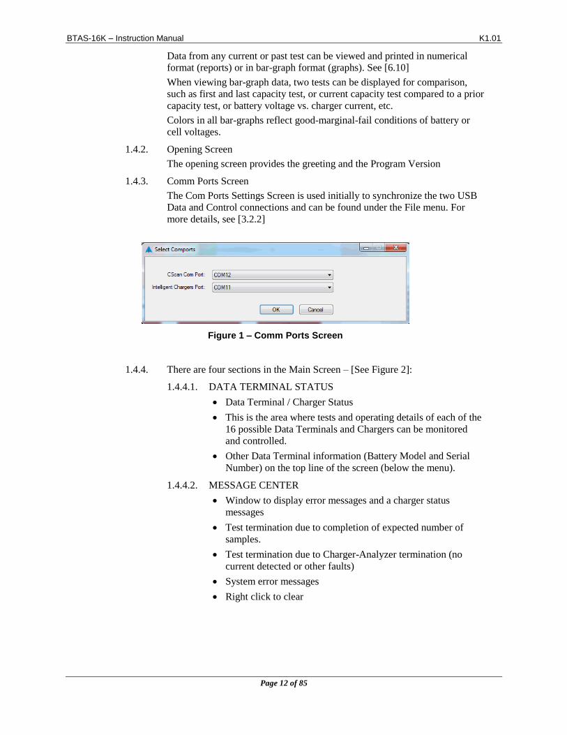
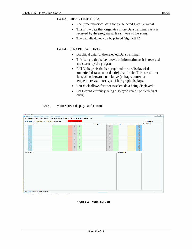

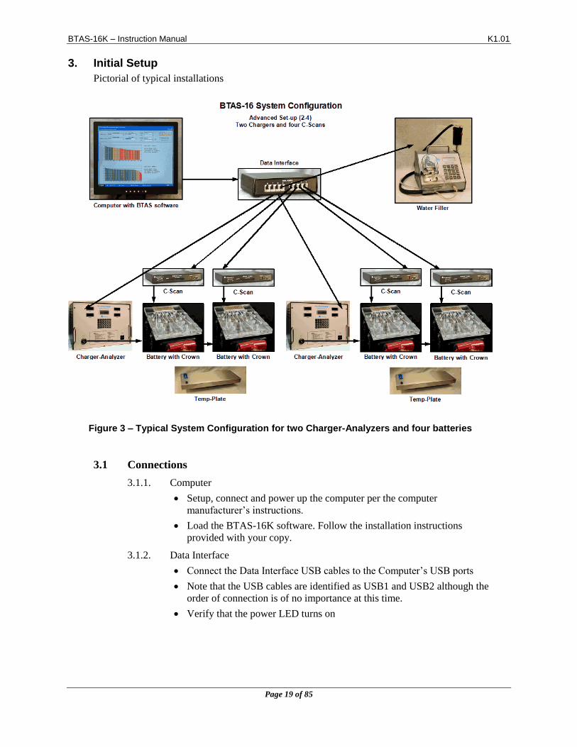
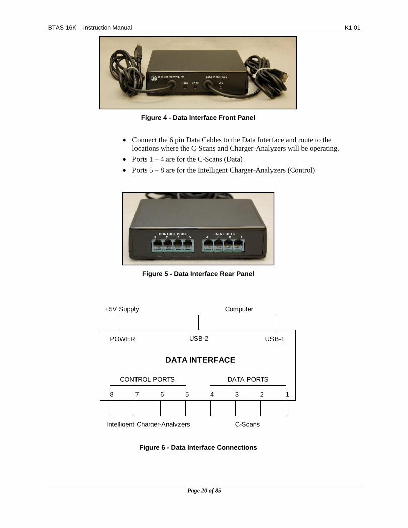
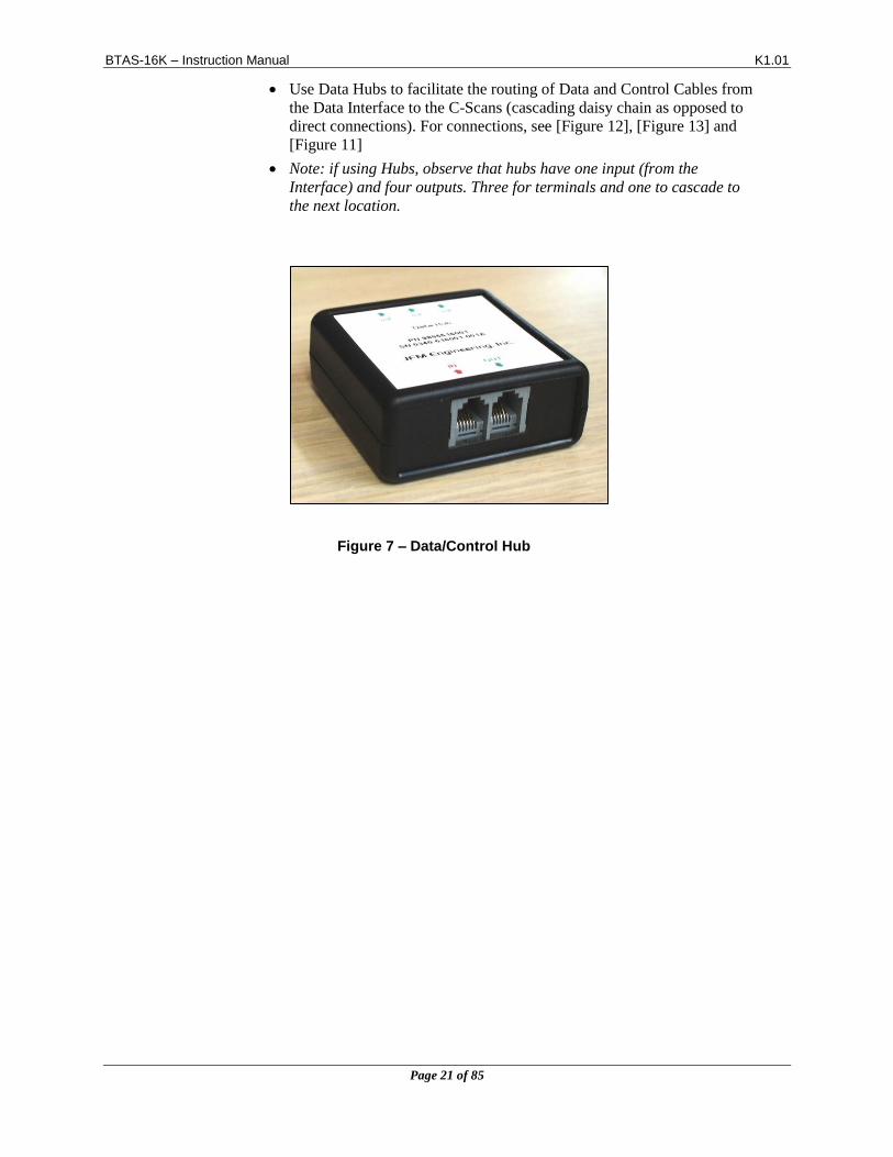
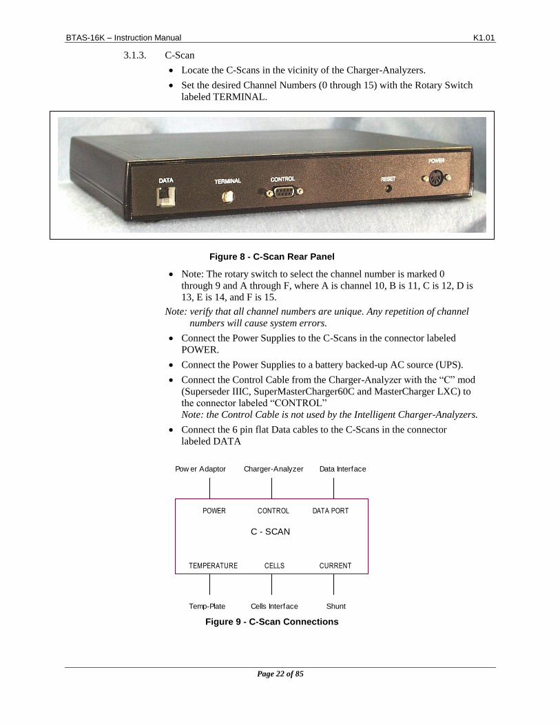
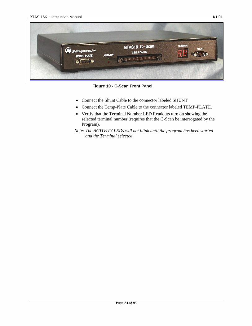
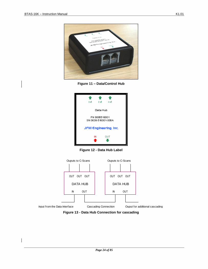
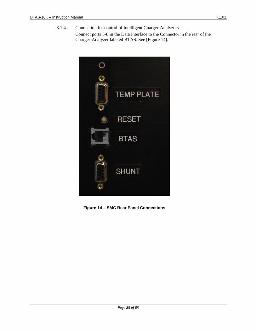
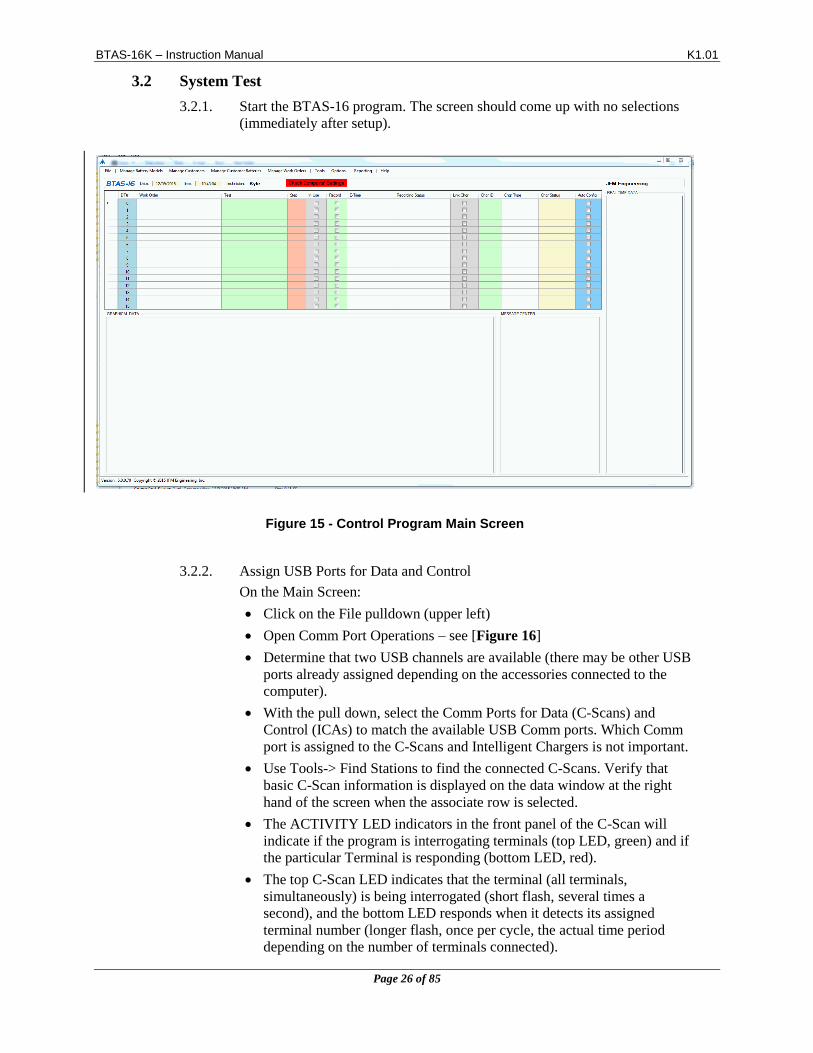
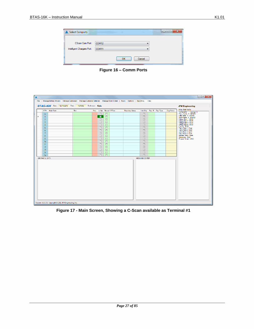
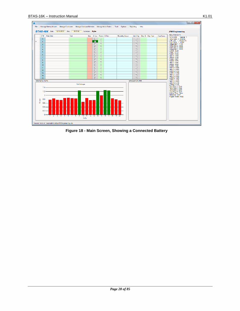
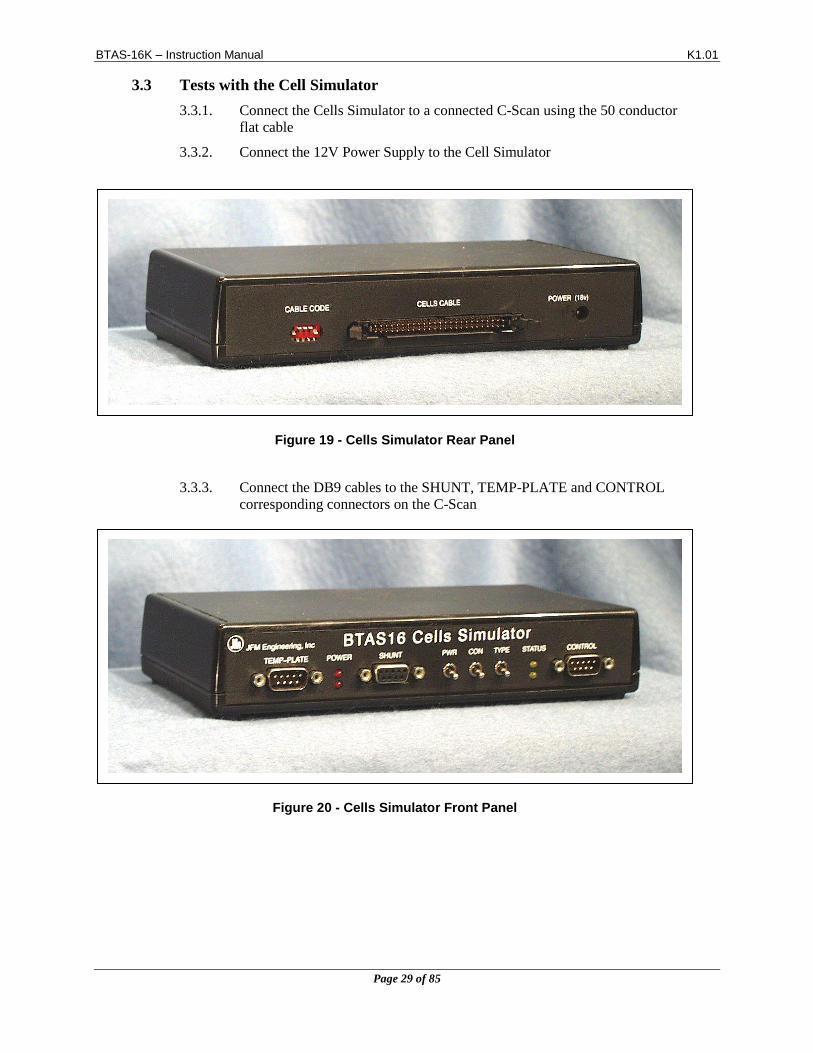
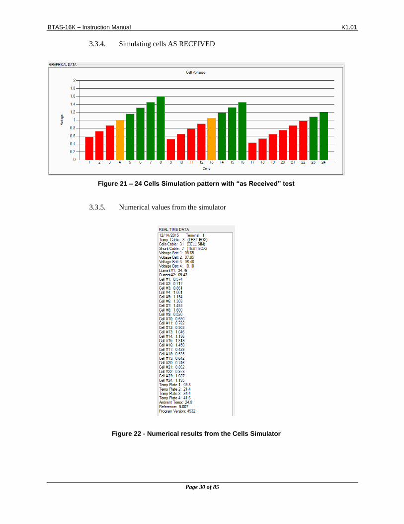
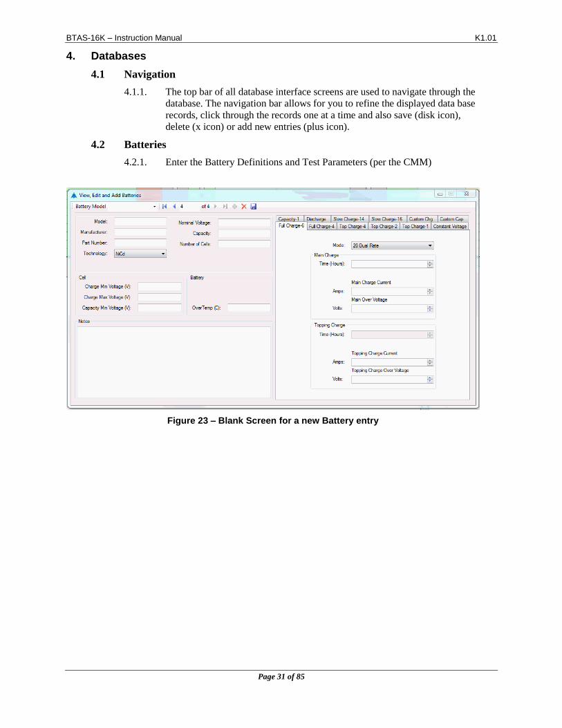
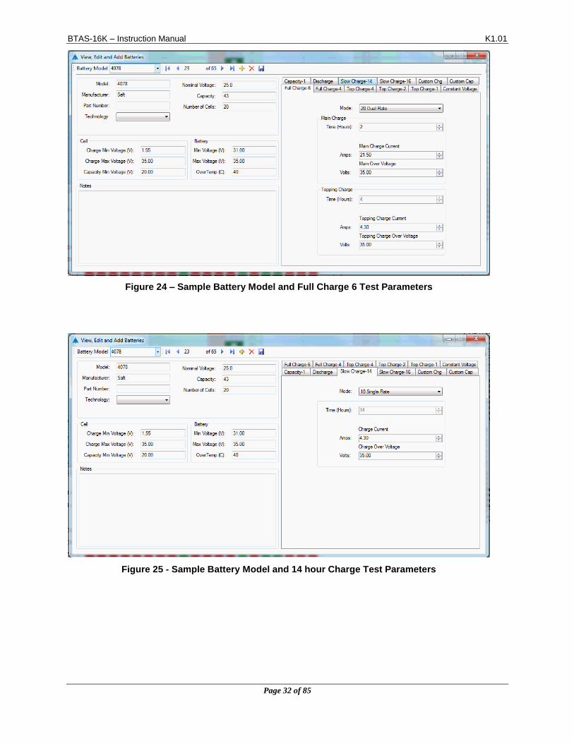
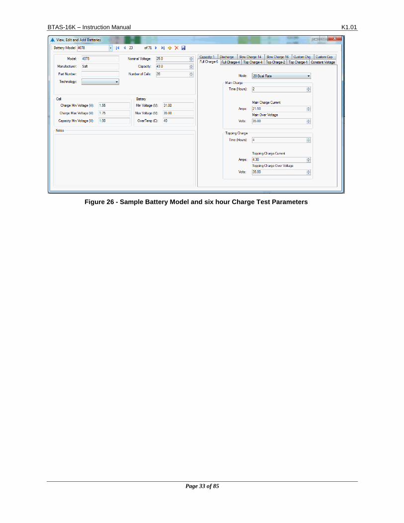
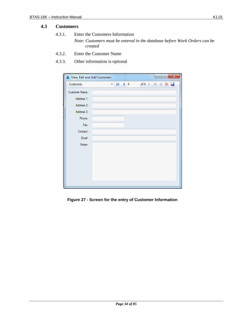
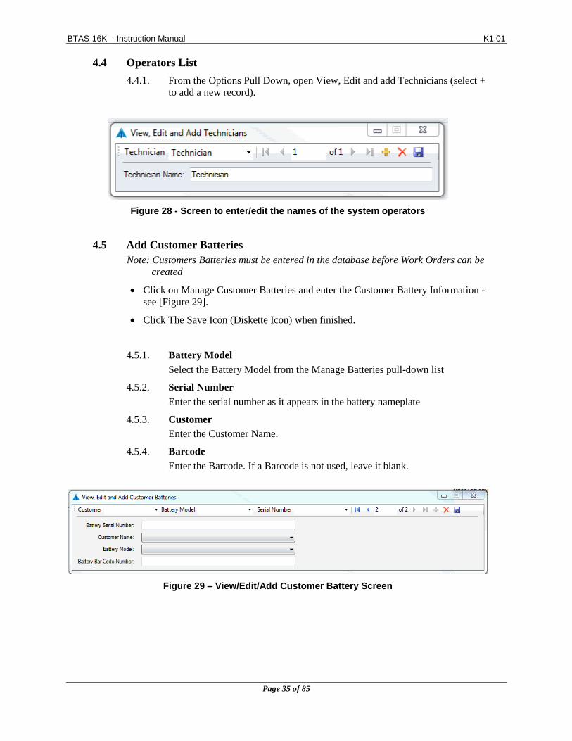
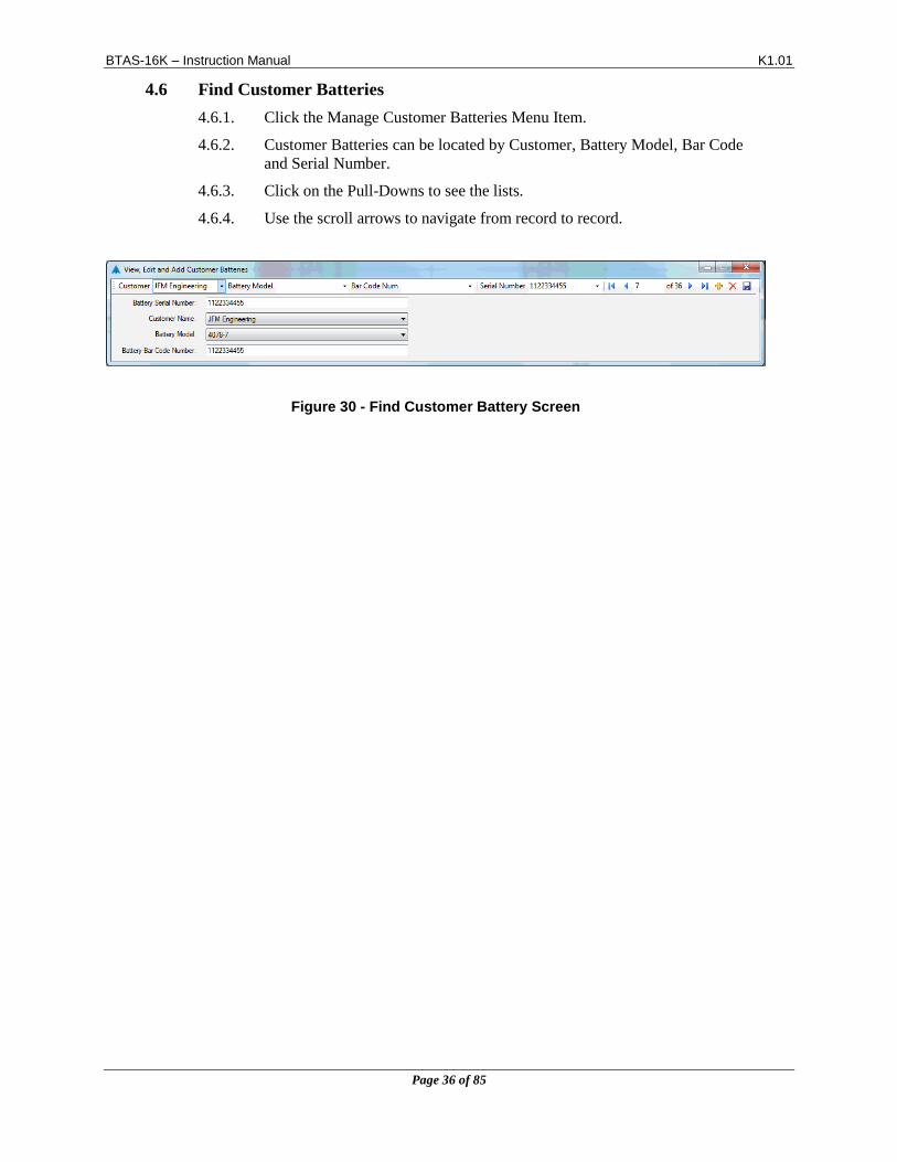
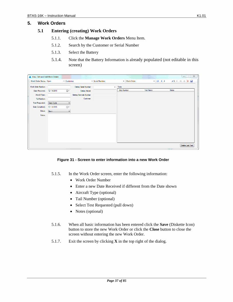
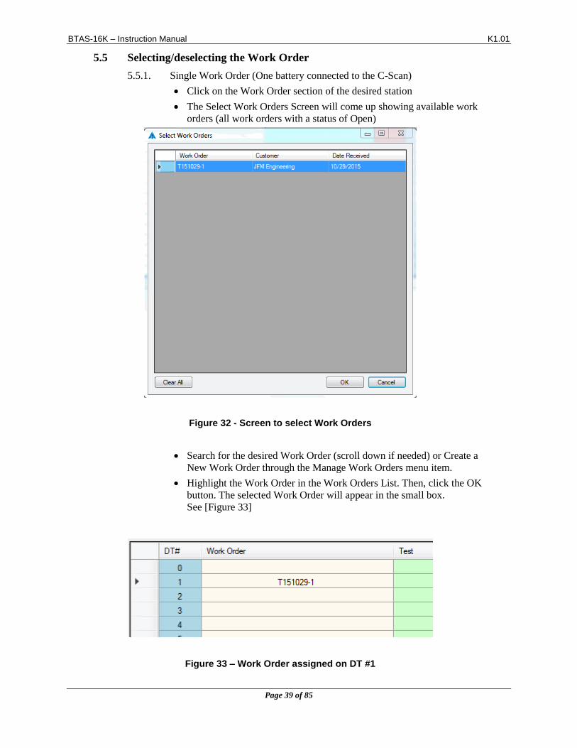
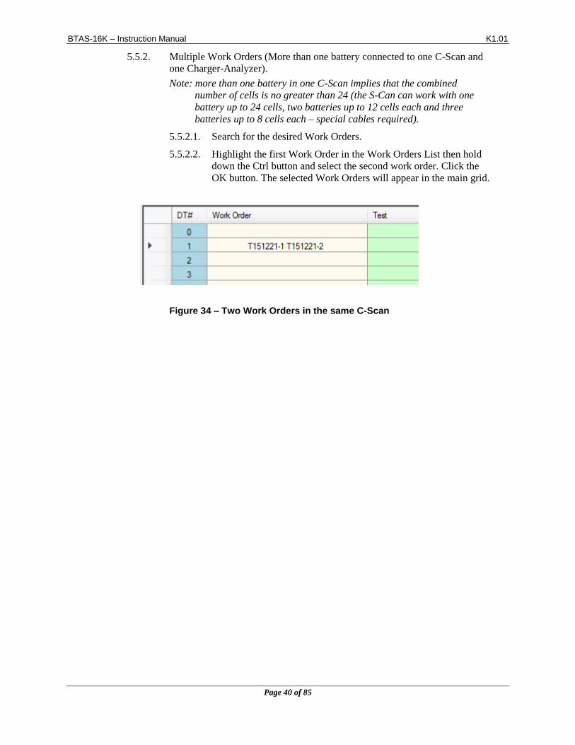
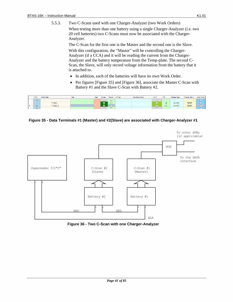
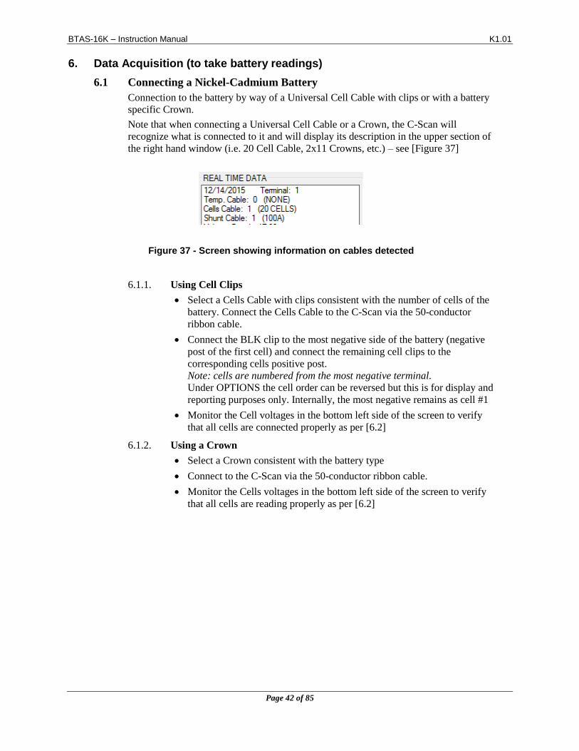
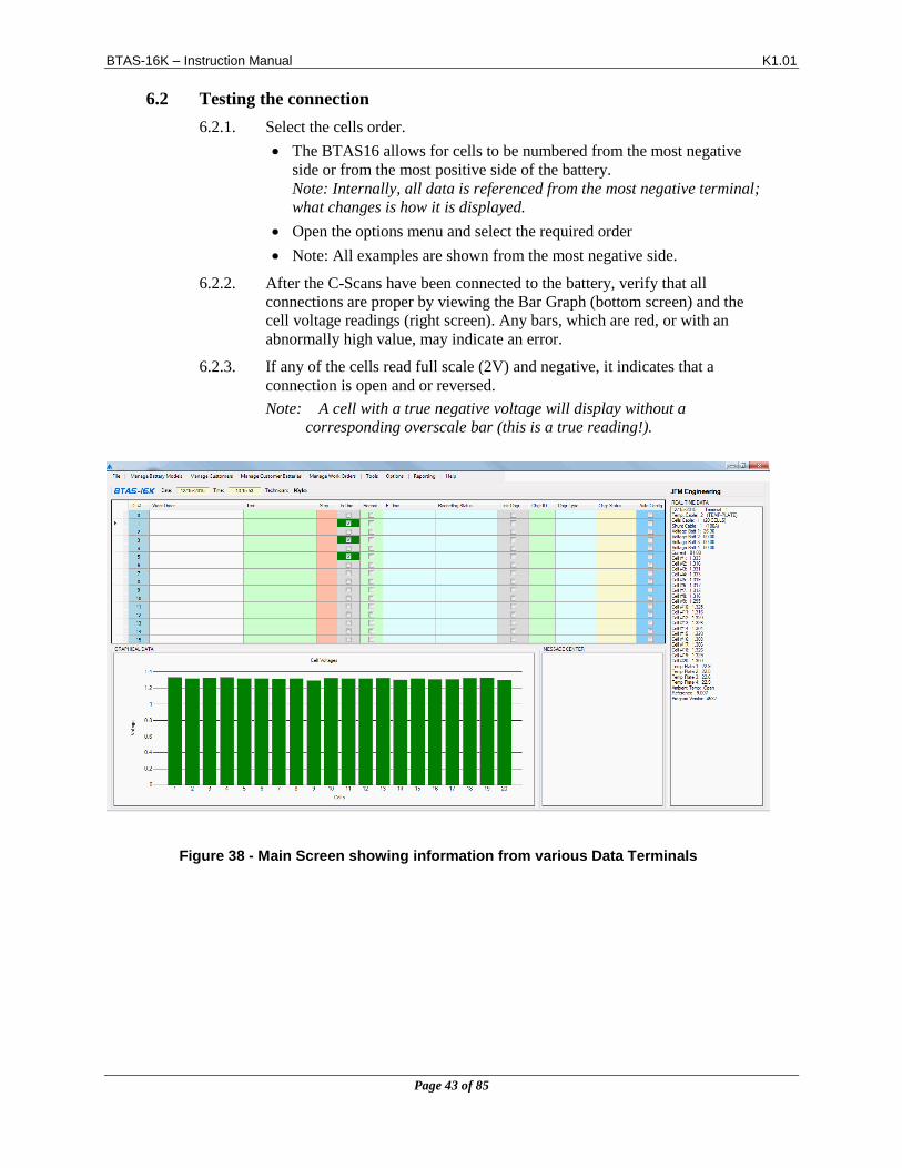
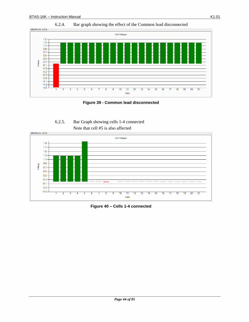
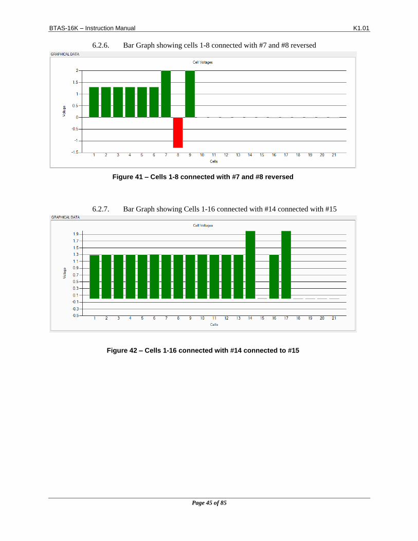
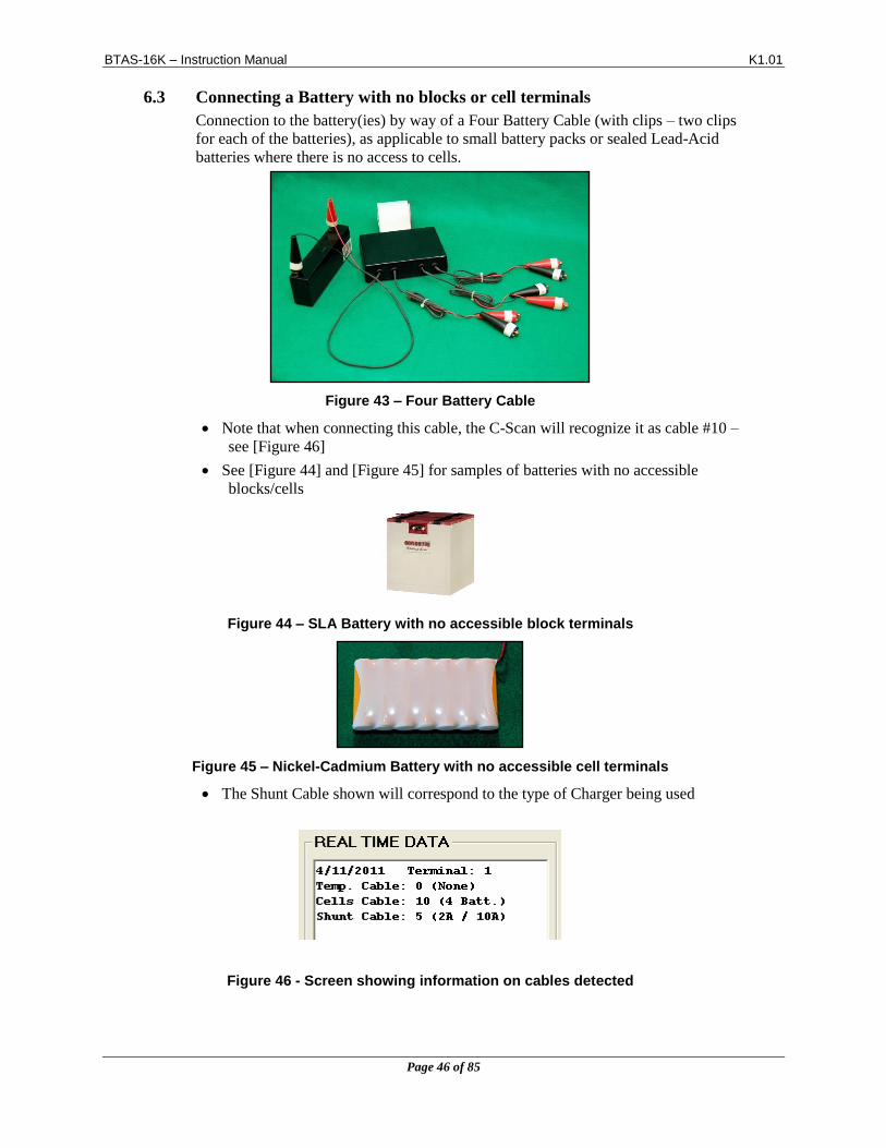
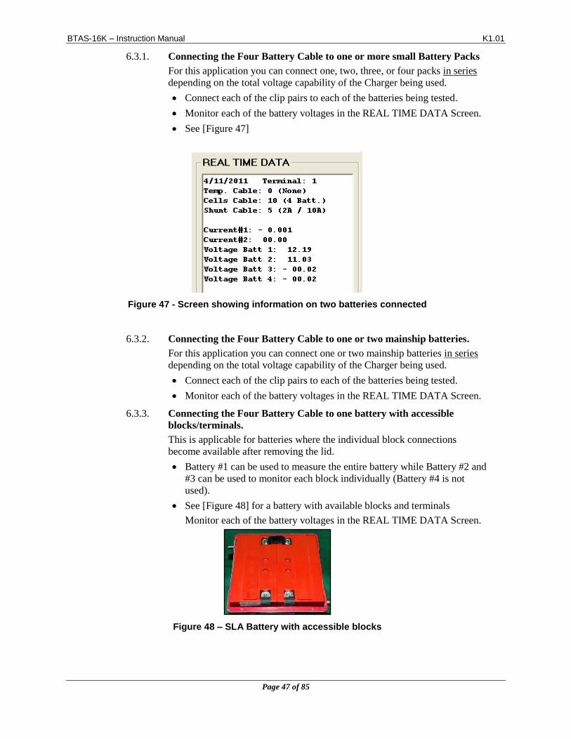
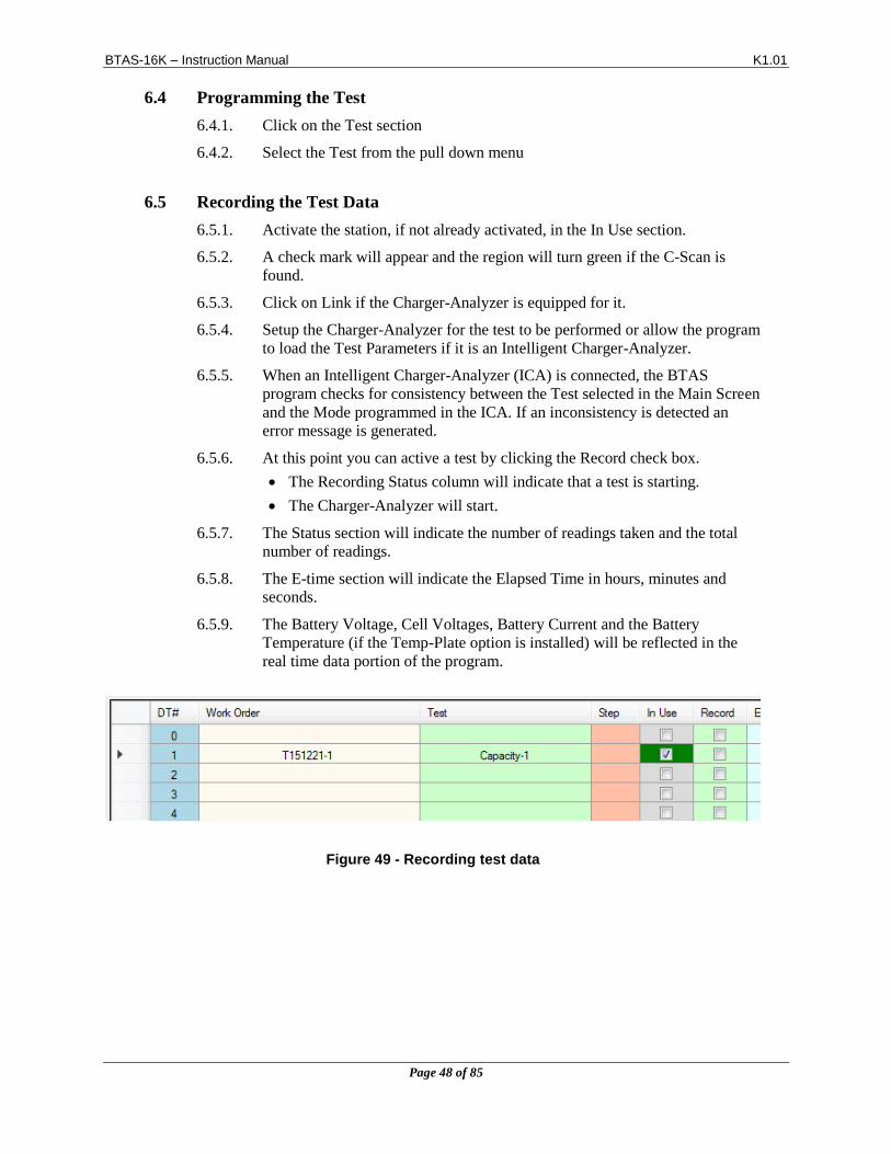
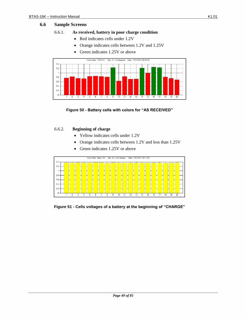
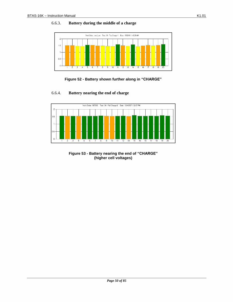
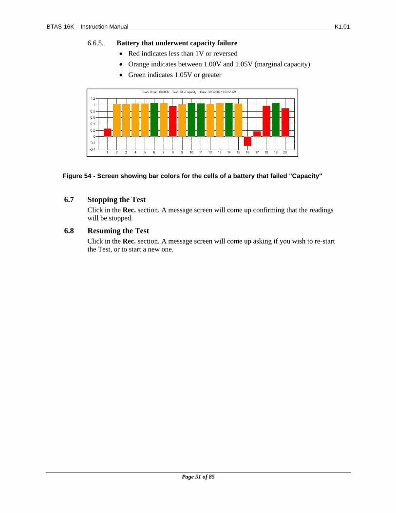
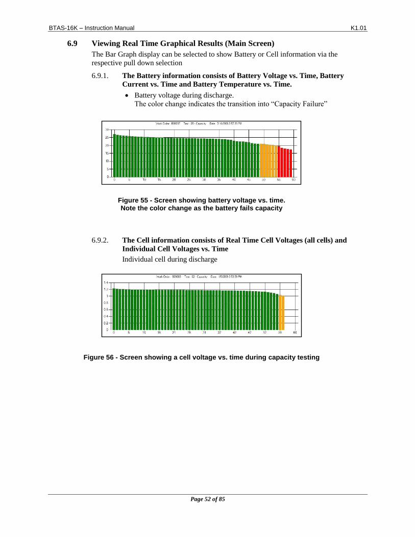
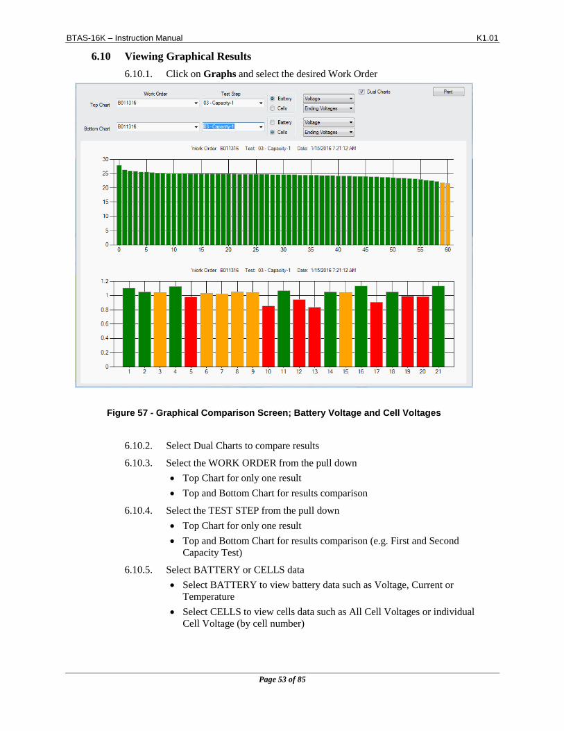
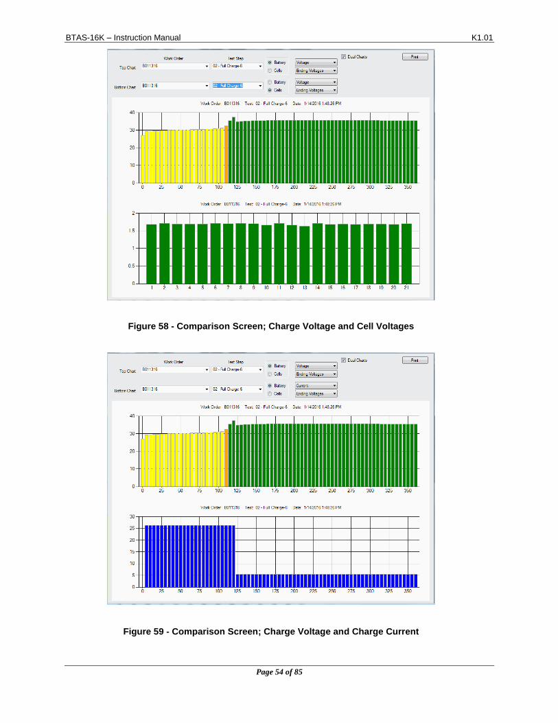
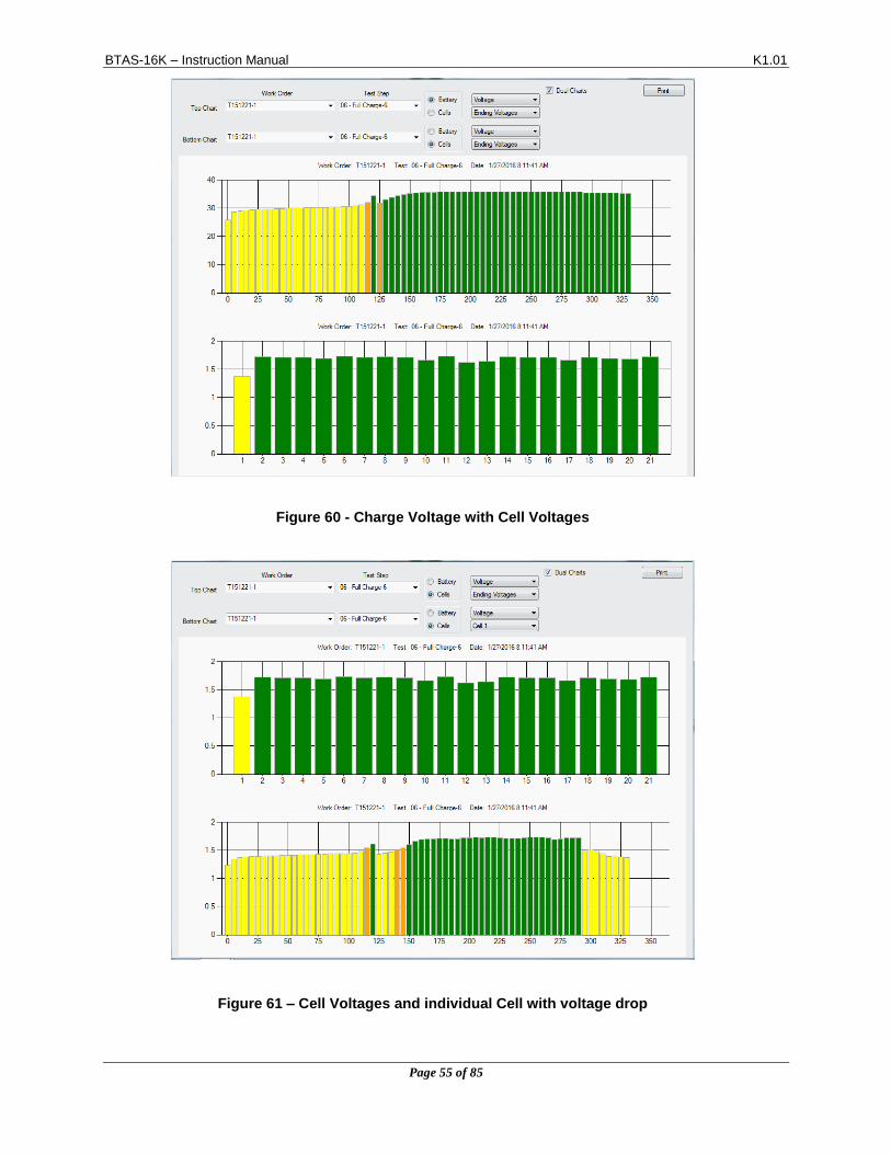
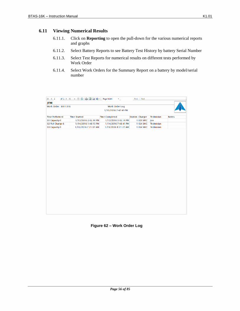
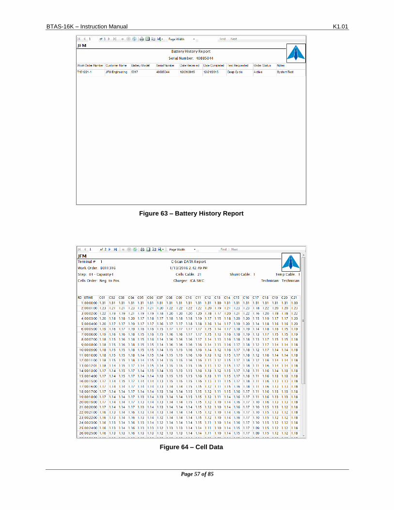
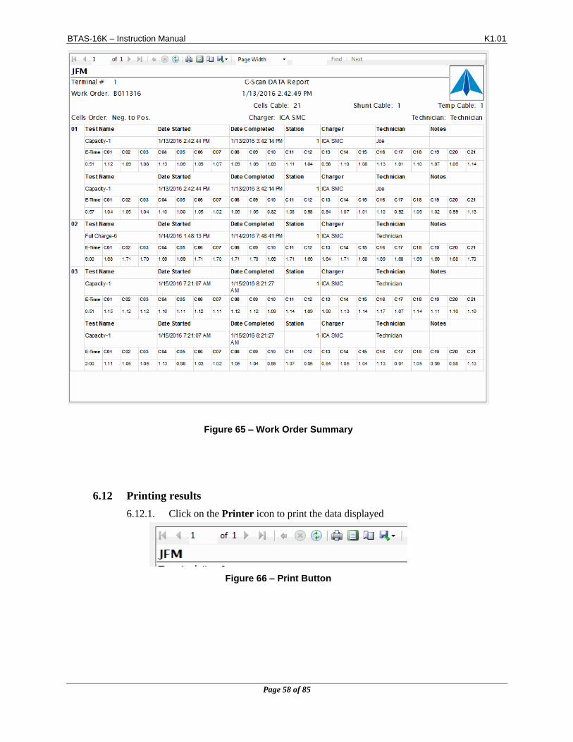
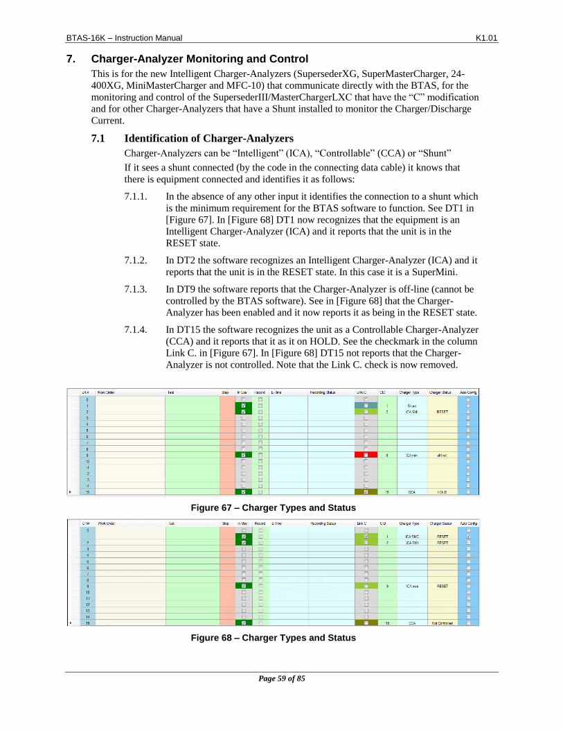
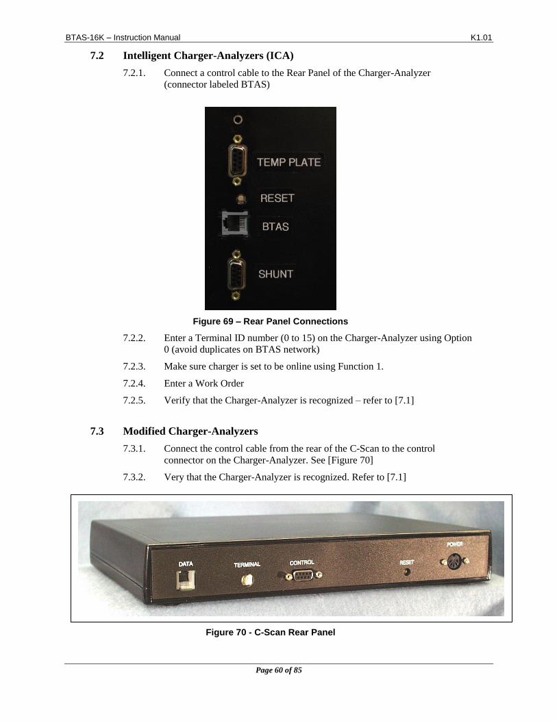
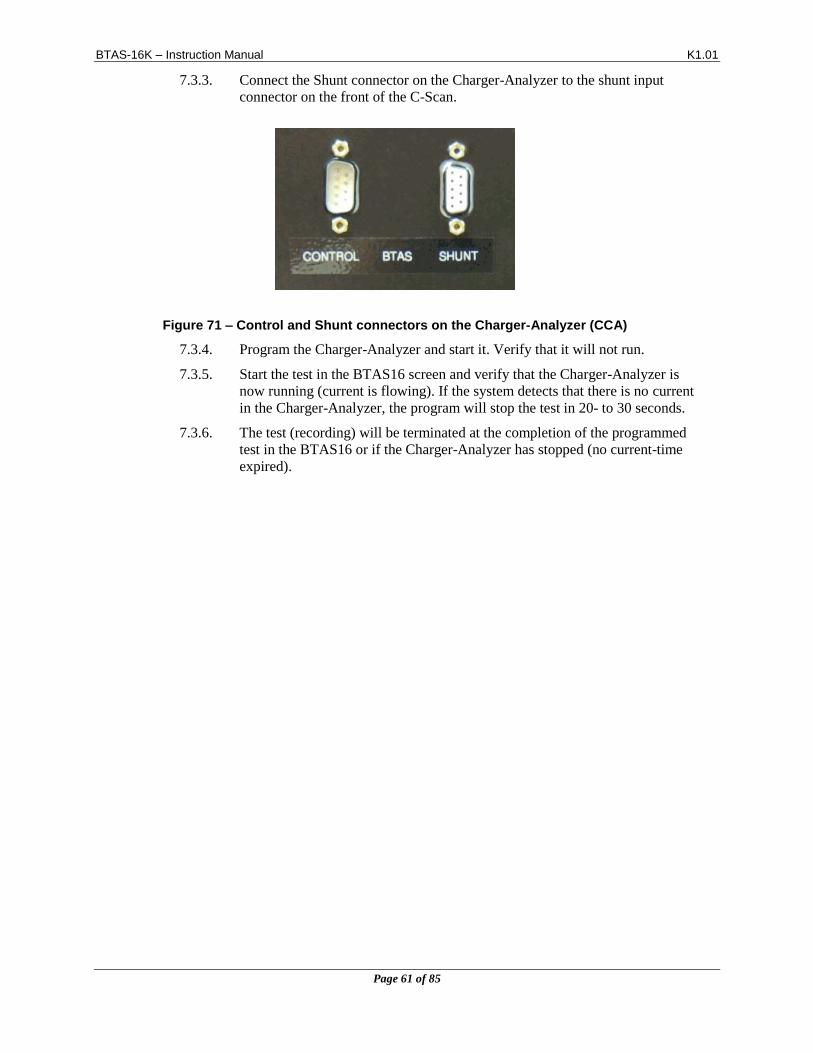
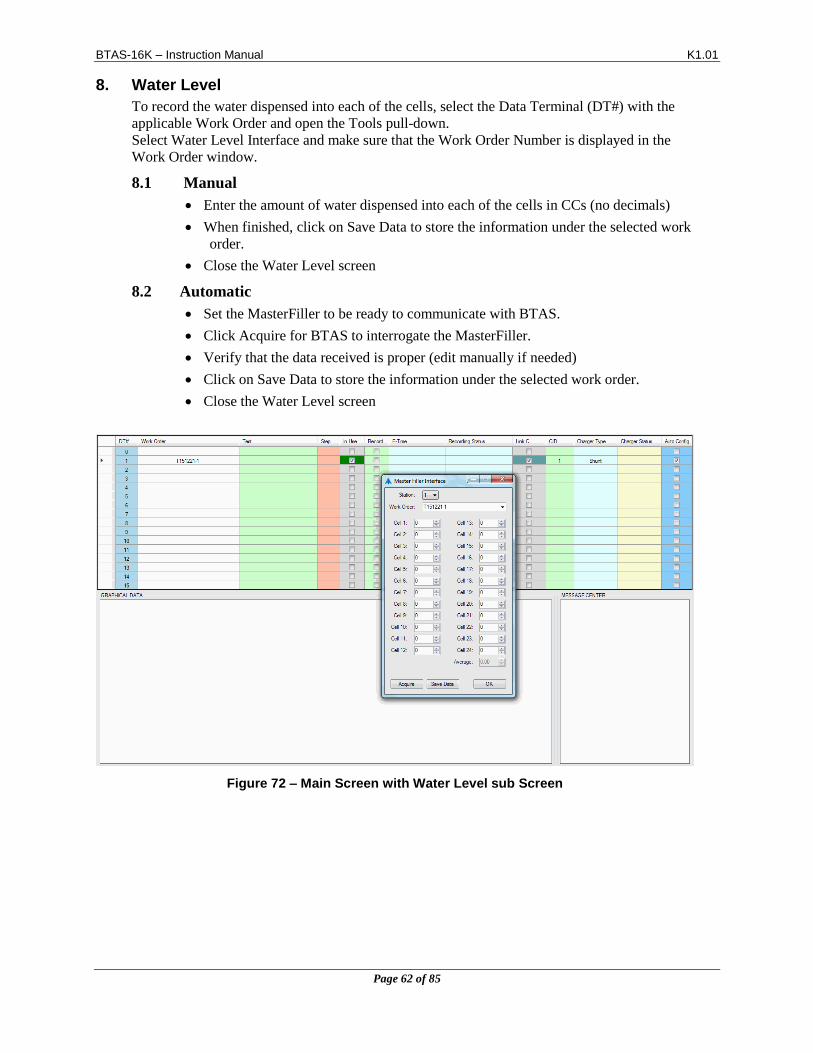
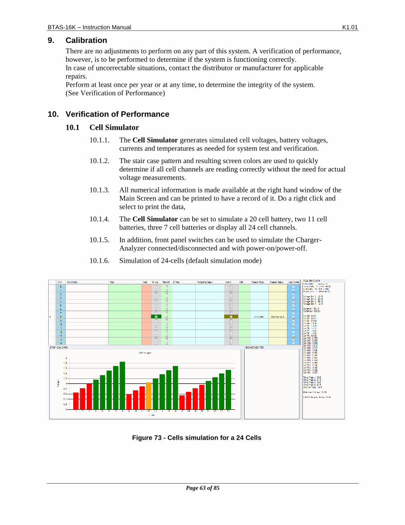
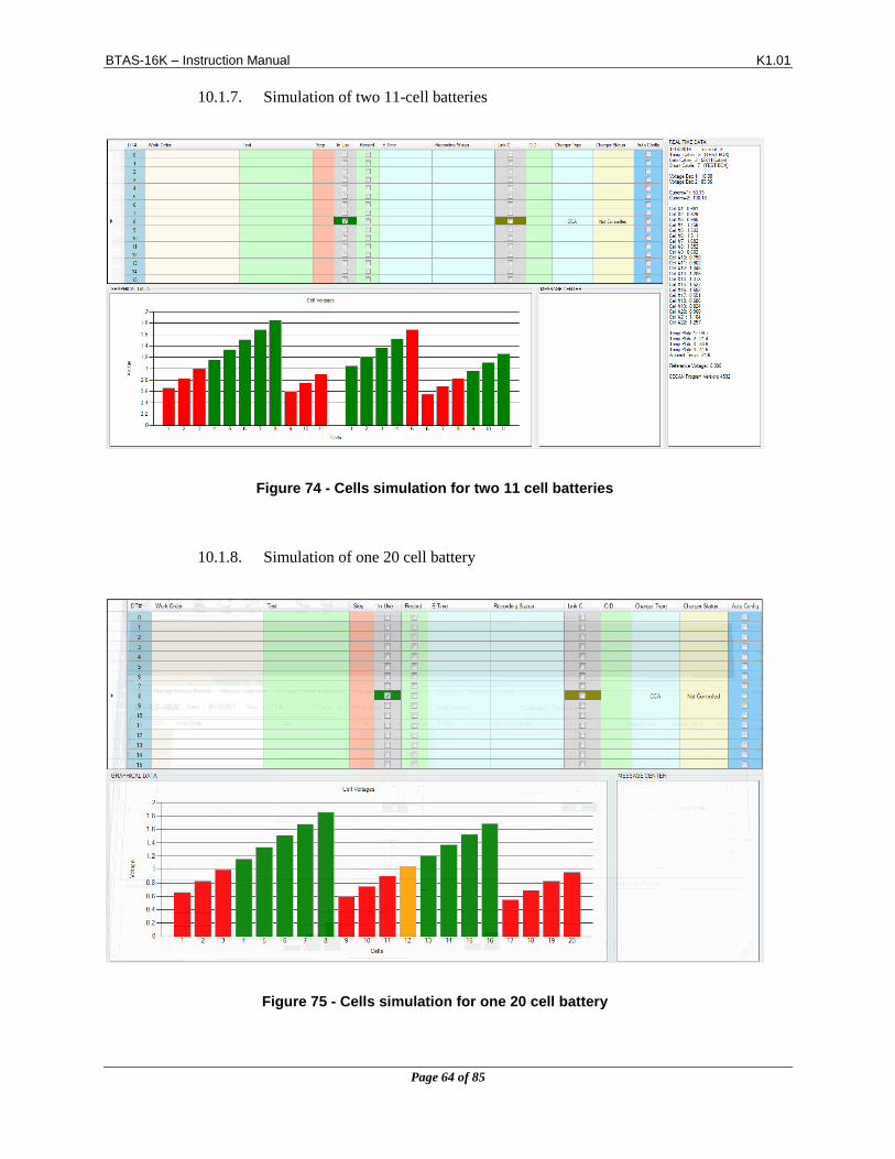
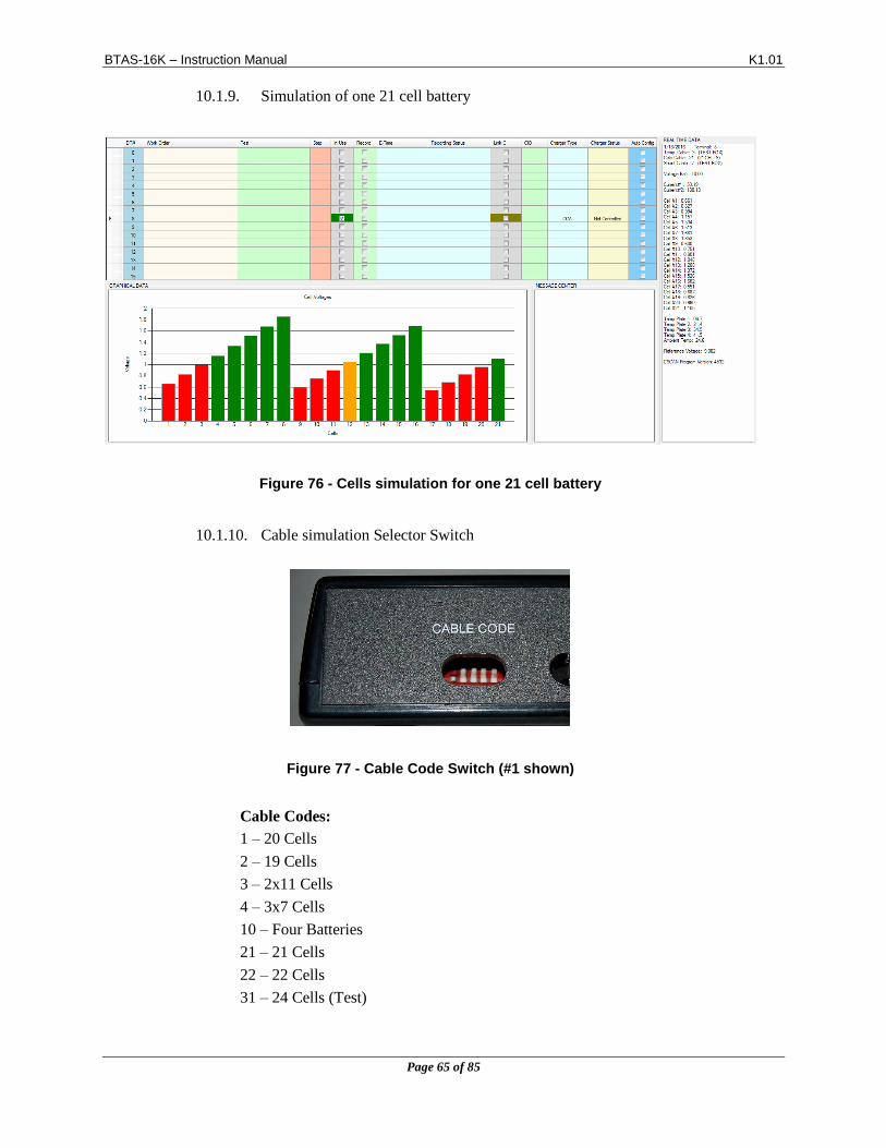
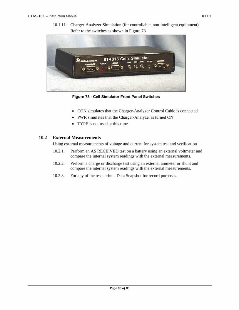
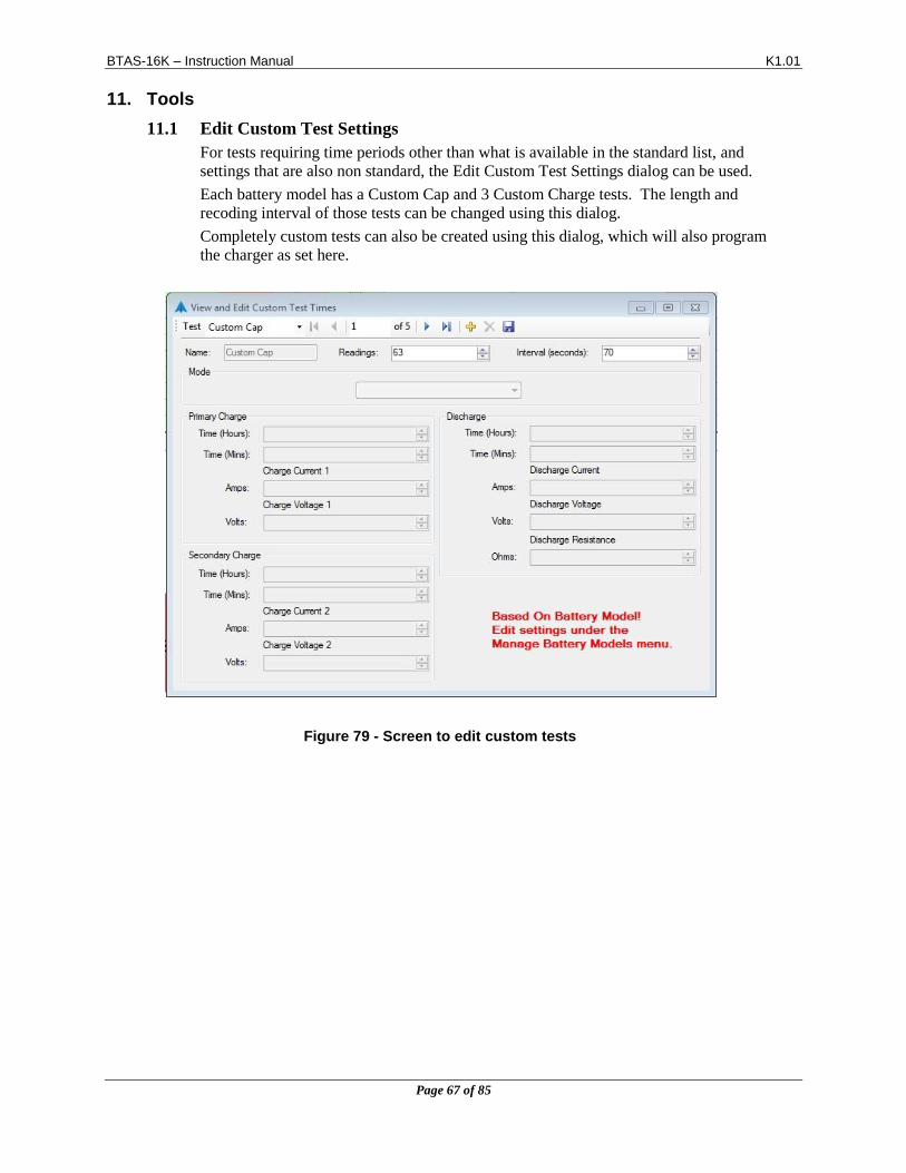
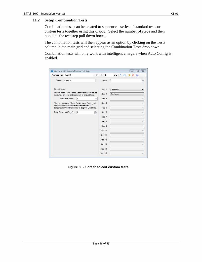
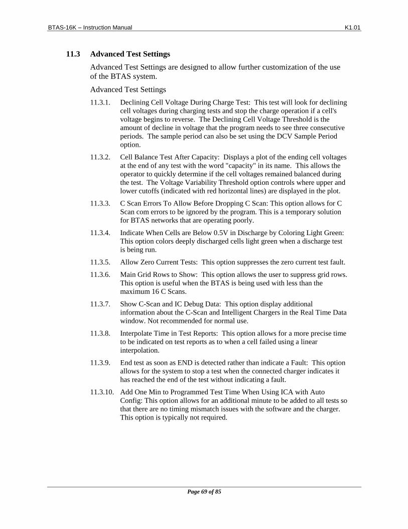
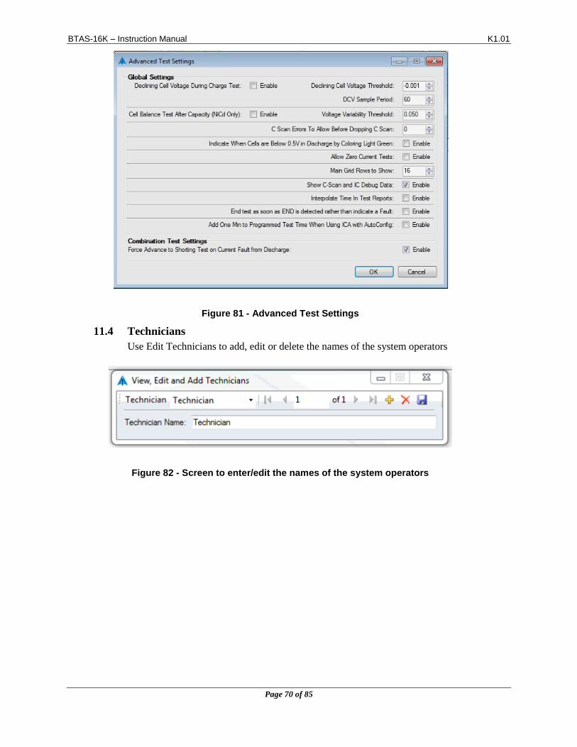
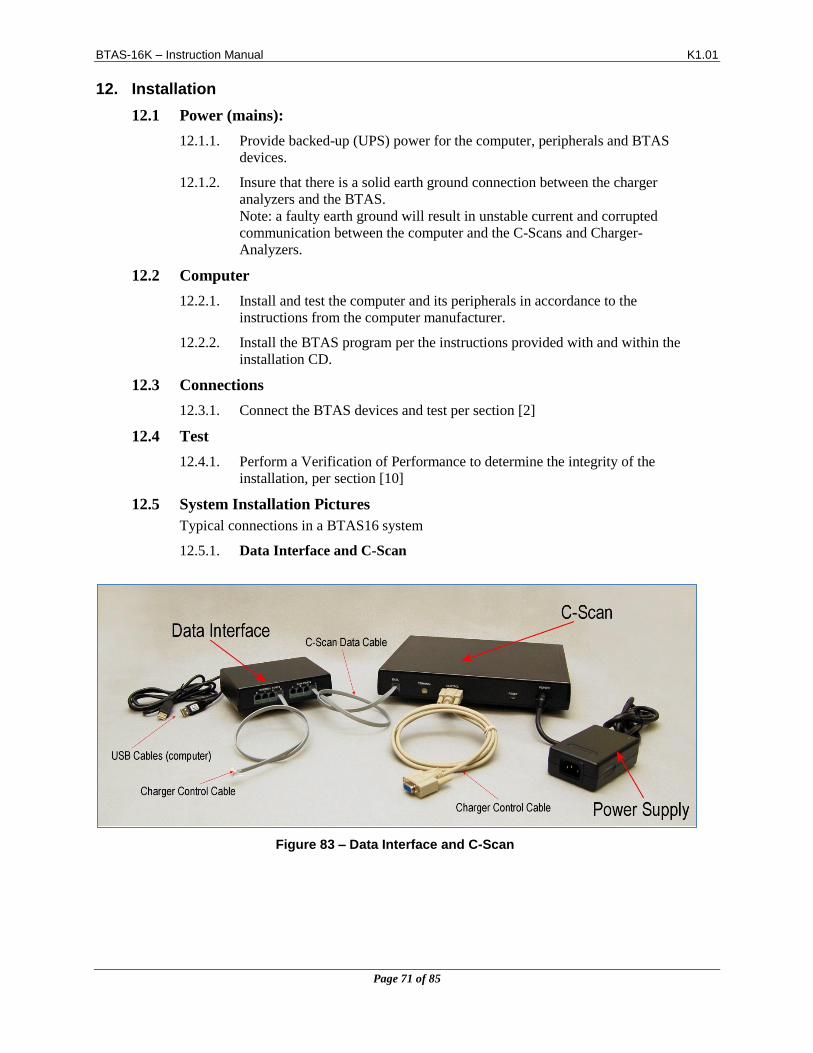
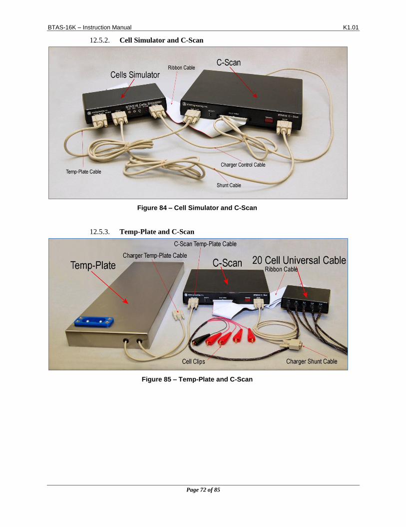
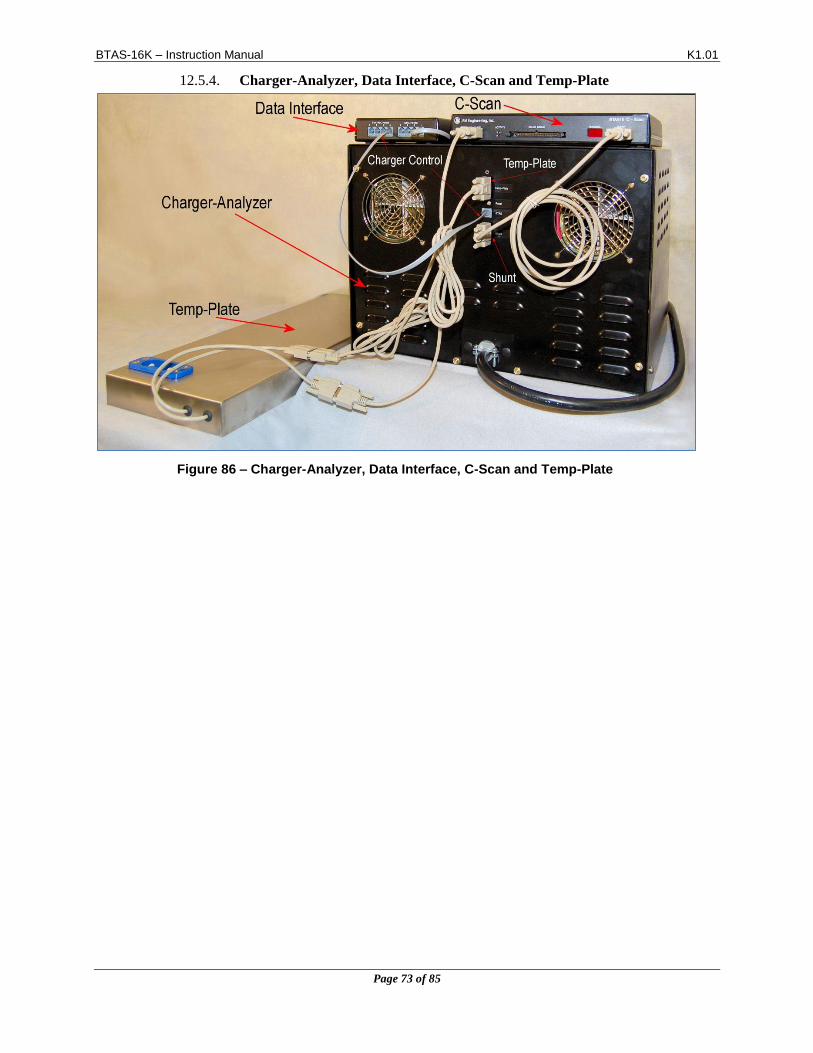
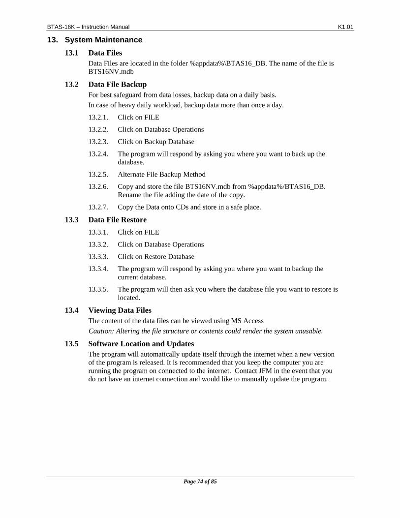
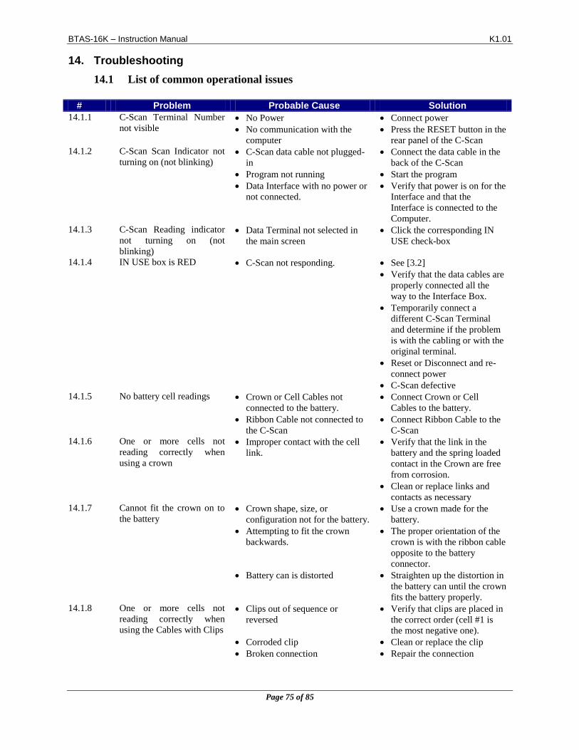
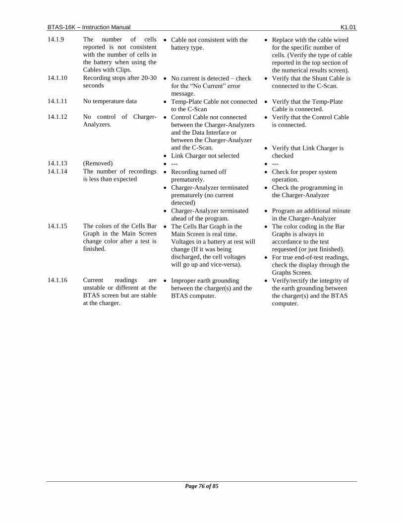
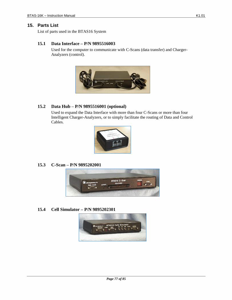
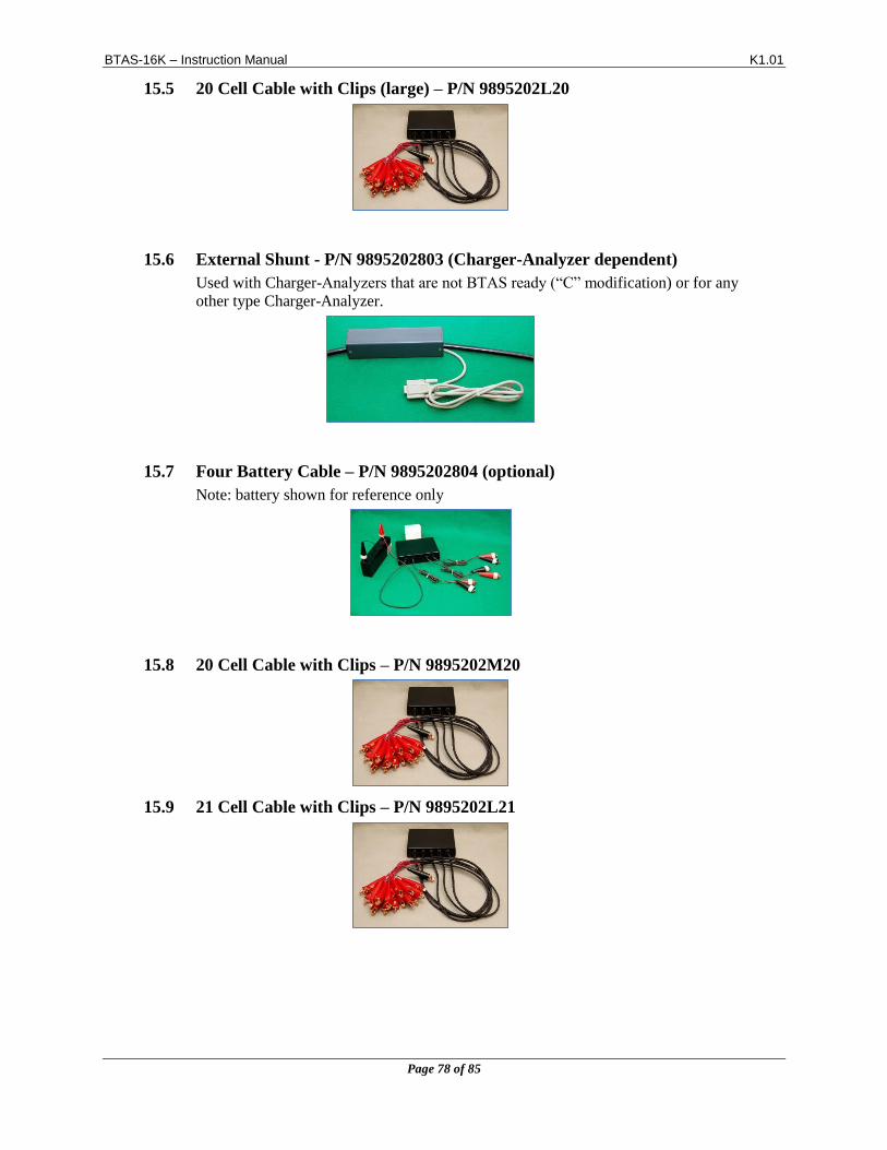
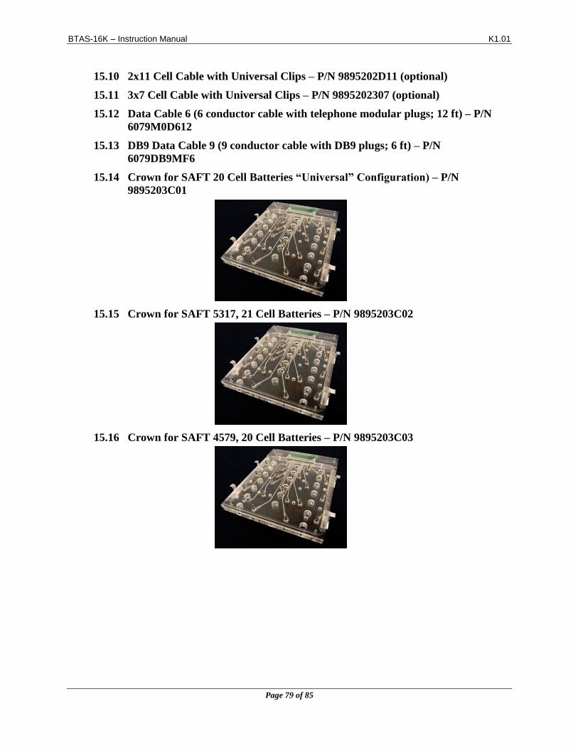

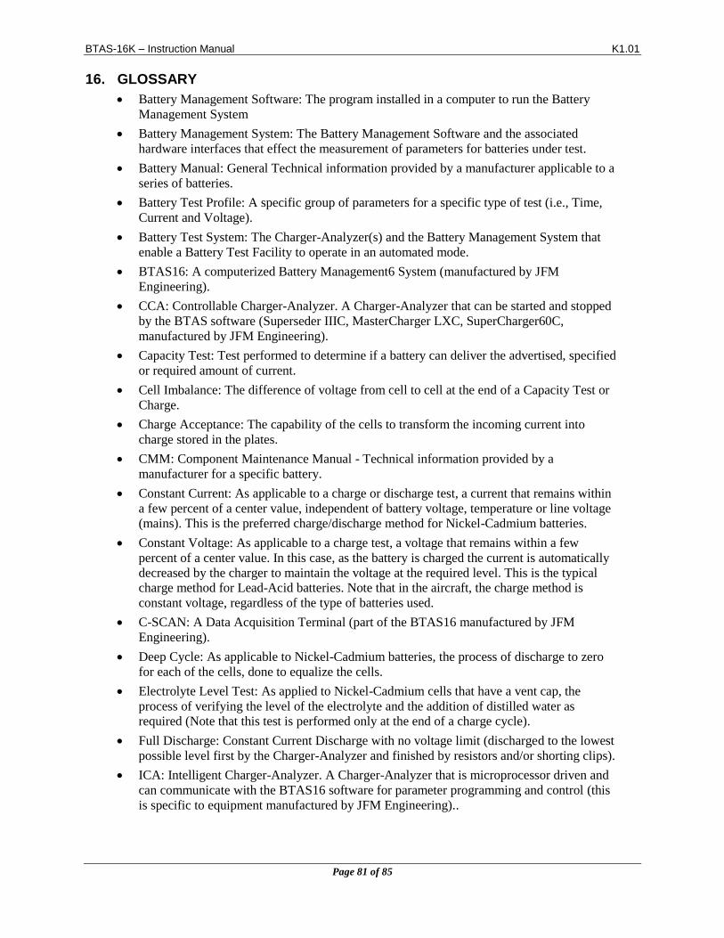

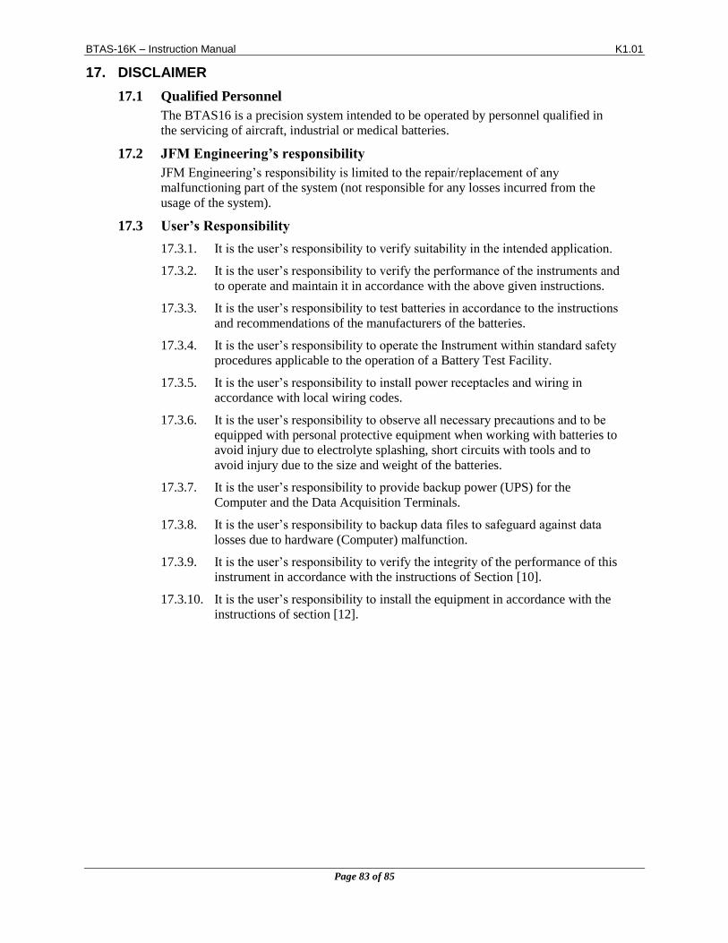
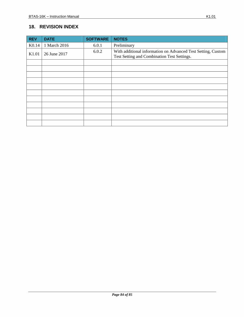


![TOPIC: 191001 KNOWLEDGE: K1.01 [3.3/3.4] QID: …...NRC Generic Fundamentals Examination Question Bank--PWR May 2019-1- Valves TOPIC: 191001 KNOWLEDGE: K1.01 [3.3/3.4] QID: P901 Which](https://static.documents.pub/doc/80x56/5ed2f41a3e92a05e0d15d63e/topic-191001-knowledge-k101-3334-qid-nrc-generic-fundamentals-examination.jpg)