1. TABLE OF CONTENTS 1. TABLE OF CONTENTS ....................................................................................................................... 1 2. GENERAL INFORMATION................................................................................................................. 1 2.1. EQUIPMENT ................................................................................................................................. 1 2.2. STANDARD SPECIFICATIONS .................................................................................................. 2 2.2.1. MODEL CODE ............................................................................................................................. 3 2.3. PRINCIPLE OF MEASUREMENT............................................................................................... 5 2.4. SENSOR DESCRIPTION .............................................................................................................. 5 2.5. THE INDICATING TRANSMITTER ........................................................................................... 7 2.6. DISPLAY AND KEYBOARD ...................................................................................................... 8 2.7. INFORMATION DISPLAY ........................................................................................................ 10 2.8. CALIBRATE ................................................................................................................................ 11 2.9. COMPATIBILITY WITH EARLIER VERSIONS ..................................................................... 13 2.10. VERSIONS OF PR-01-S.............................................................................................................. 14 2.11. PASSWORD ................................................................................................................................ 15 2.12. WARRANTY ............................................................................................................................... 15 3. MOUNTING ........................................................................................................................................ 16 3.1. SENSOR LOCATION ................................................................................................................. 16 3.2. MOUNTING EXAMPLES .......................................................................................................... 18 3.3. MOUNTING AND DISMOUNTING.......................................................................................... 21 3.4. WASH NOZZLE FOR STEAM................................................................................................... 21 3.5. INDICATING TRANSMITTER.................................................................................................. 21 3.6. ELECTRICAL CONNECTIONS................................................................................................. 22 3.7. SERIAL OUTPUT ....................................................................................................................... 25 3.8. FUSES .......................................................................................................................................... 28 4. START UP ........................................................................................................................................... 29 4.1. INITIAL CHECK ......................................................................................................................... 29 4.2. CALIBRATION CHECK............................................................................................................. 29 4.3. DEMO MODE.............................................................................................................................. 29 5. CALIBRATION ................................................................................................................................... 31 5.1. OUTPUT CURRENT RANGE SELECTION ............................................................................. 31 5.2. CONCENTRATION CALIBRATION FROM KEYBOARD ..................................................... 31 5.3. FIELD CALIBRATION ............................................................................................................... 32 5.4. BENCH CALIBRATION............................................................................................................. 32 5.5. MECHANICAL ZERO ADJUSTMENT ..................................................................................... 33 5.6. SENSOR RANGEABILITY ........................................................................................................ 34 5.7. EEPROM PARAMETERS........................................................................................................... 35 5.8. TEMPERATURE CALIBRATION ............................................................................................. 36 6. MAINTENANCE ................................................................................................................................. 37 6.1. REGULAR MAINTENANCE ..................................................................................................... 37 6.2. DIAGNOSTICS............................................................................................................................ 37 6.3. DISPLAY MESSAGES ............................................................................................................... 40 6.4. INDICATING TRANSMITTER.................................................................................................. 44 6.5. SENSOR CHECK ........................................................................................................................ 50 6.6. TEMPERATURE MEASUREMENT .......................................................................................... 56 6.7. PRISM GASKET REPLACEMENT............................................................................................ 56 6.8. SENSOR DISASSEMBLY .......................................................................................................... 58 6.9. OPTICAL MODULES TESTING ............................................................................................... 59 6.10. LED CURRENT ADJUSTMENT................................................................................................ 60 INSTRUCTION MANUAL FOR K-PATENTS PR-01-S (-EX/FM) DOCUMENT/REVISION No. INM 1/4 Effective: March 19th, 1999
Transcript
1. TABLE OF CONTENTS
1. TABLE OF CONTENTS ....................................................................................................................... 1
2. GENERAL INFORMATION................................................................................................................. 12.1. EQUIPMENT ................................................................................................................................. 12.2. STANDARD SPECIFICATIONS.................................................................................................. 22.2.1. MODEL CODE............................................................................................................................. 3
2.3. PRINCIPLE OF MEASUREMENT............................................................................................... 52.4. SENSOR DESCRIPTION.............................................................................................................. 52.5. THE INDICATING TRANSMITTER ........................................................................................... 72.6. DISPLAY AND KEYBOARD ...................................................................................................... 82.7. INFORMATION DISPLAY ........................................................................................................ 102.8. CALIBRATE................................................................................................................................ 112.9. COMPATIBILITY WITH EARLIER VERSIONS ..................................................................... 132.10. VERSIONS OF PR-01-S.............................................................................................................. 142.11. PASSWORD ................................................................................................................................ 152.12. WARRANTY ............................................................................................................................... 15
8. PRISM WASH SYSTEMS .................................................................................................................. 658.1. PRISM COATING ....................................................................................................................... 658.2. PRISM WASH WITH INTEGRAL STEAM NOZZLE .............................................................. 658.3. PRISM WASH WITH INTEGRAL HIGH PRESSURE WATER NOZZLE.............................. 708.4. PRISM WASH WITH FLOW THROUGH CELLS .................................................................... 758.5. RECOMMENDED WASH PRESSURES AND TIMES............................................................. 78
9. RELAY UNIT ...................................................................................................................................... 799.1. CONNECTIONS.......................................................................................................................... 809.2. RELAY UNIT CONFIGURATION............................................................................................. 819.3. COMPATIBILITY ....................................................................................................................... 829.4. WASH LOGICS AND SMART WASH...................................................................................... 82
10. ACCESSORY UNITS...................................................................................................................... 8510.1. EXTERNAL OUTPUT UNIT PR-7090................................................................................... 8510.2. DIVERT CONTROL UNIT DD-01 ......................................................................................... 86
11. RETRACTOR WITH ISOLATION VALVE HIMP-2 .................................................................... 8711.1. EQUIPMENT ........................................................................................................................... 8711.2. RETRACTOR WITH ISOLATION VALVE PARTS LIST.................................................... 8911.3. MOUNTING ............................................................................................................................ 9011.4. RETRACTION AND INSERTION ......................................................................................... 9211.5. BALL VALVE ......................................................................................................................... 93
13. K-PATENTS PROCESS REFRACTOMETER CALIBRATION DATA REPORT..................... 105
INSTRUCTION MANUAL FOR K-PATENTS PR-01-S (-EX/FM) DOCUMENT/REVISION No. INM 1/4Effective: March 19th, 1999
1
2. GENERAL INFORMATION
2.1. EQUIPMENT
The K-Patents Process Refractometer consists of three parts (Figure 2.10): the Sensor (A), the InterconnectingCable (B) and the Indicating transmitter (C). For description of the intrinsically safe K-Patents ProcessRefractometer, see Chapter 12.
SERIAL NUMBER
A B C
A B C D
7
4
1
0
8
5
2
.
9
6
3
- ESET
K-PATENTSPROCESS INSTRUMENTS
ENTER R
Figure 2.10 EquipmentFor intrinsically safe equipment, see Figure 12.10.
The K-Patents Process Refractometer provides a 4 to 20 mA DC output signal proportional to processsolution concentration. A serial output is also available as a standard.
Identification: By Serial Number (S/N) label (Figure 2.11) on the Indicating transmitter front panel and bySerial number on sensor label (Figure 2.10, Figure 2.12), e.g. 92A25-1088. The sensor type, e.g. 57, isstamped on the probe tip (Section 5.6).
Figure 2.12 Identification label, Sensor.For intrinsically safe sensor label, see Figures 12.11, 12.12 and 12.13.
INSTRUCTION MANUAL FOR K-PATENTS PR-01-S (-EX/FM) DOCUMENT/REVISION No. INM 1/4Effective: March 19th, 1999
2
2.2. STANDARD SPECIFICATIONS
Refractive Index ranges: Low range R.I. 1.320...1.460
4,5 kg (10 lbs)(We reserve right to technical alterations.)
High range R.I. 1.380...1.530Max. span:
Alarms: Two built-in signal relays, max 24V, 500 mA
R.I. 0.08 (See Section 5.6)Accuracy: R.I. ± 0.0002 (corresponds typically to ± 0.1% by weight).
Repeatability and stability correspond to accuracy.
Options: - Long probe version (-LP). Probe length is 152 mm (6") longerthan standard.
- Wetted parts: Hastelloy C, titanium or palladium doped titanium- Cable fittings to the Indicating transmitter: European cable glands
or US conduit hubs, see Section 7.3.
Speed of response: 0.8 s undamped
- Built-on prism wash nozzle, see Section 8.3.- Intrinsically Safe PR-01-S-EX/FM, see Section 12.
BASEEFA approved EExia IIC T4 (Tamb=45 °C)Factory Mutual (FM) approved Class I, Div. 1, Groups A, B, C,D T4 (T =45 °C)
Damping time constant: Selectable up to 5 min
amb
Accessories:
Process temperature: max. 150°C (300°F), (for higher temp. consult factory)
- External output unit, Section 10.1- Digital Divert Control Unit DD-01, Section 10.2- Retractor and isolation valve, Chapter 11.- Prism wash nozzles for steam and hot water, Section 3.4.
Ambient temperature: Sensor: max. 45°C (113°F), min. -20°C (-4°F),
- Flow cells according to separate drawings available fromK-Patents.
Indicating transmitter: max. 50°C (122°F), min. 0°C (32°F)
Ordering information:- Desired scale, properties of process solution- Process temperature and pressure range
Process pressure: Flange connections up to 25 bar (350 psi)Sanitary clamp max. 15 bar (200 psi) at 20 °C (70 °F)/9 bar (125psi) at 120 °C (250 °F)
- Process flow range and pipe diameter- Desired process connection
- Length of interconnecting cable
Recommended flow velocity: above 1.5 m/s (5 ft/s)
- Supply voltage and frequency- Options and accessories- User tag
V DC or AC (peak), Built-in hold function during prism wash.Serial output: RS485/RS232
Galvanic isolation 500 V DC or AC (peak)Power: 100-115 V/220-240 V, 50/60 Hz, 15 VAInterconnecting cable: Shielded cable, 2 twisted pairs with individual shields, 0.5 mm2.
Digital transmission according to RS485.Interconnecting cable length: Standard 10 m (33 ft), max. 100 m (330 ft)Indicating transmitter: Enclosure IP66 Nema 4XIndicating transmitter weight:
INSTRUCTION MANUAL FOR K-PATENTS PR-01-S (-EX/FM) DOCUMENT/REVISION No. INM 1/4Effective: March 19th, 1999
3
2.2.1. MODEL CODE
-FM = FM approved IS CL.1,DIV.1 GRP.A,B,C,D T4 -FM
- GP = General purpose- CS =
-GP
Model and Description Model
.............-STD = Standard
PR-01-S = Sensor PR-01-S
-STD
............-WR = Wash control relay unit, 2-relays
Refractive Index range limits........................................................................................................................ .............50= Low range R.I. 1.320....1.460
-LPL = Long probe, insertion length 299mm (b)(e) -LPL-LPS = Long probe, insertion length 147mm (b)(e)
.............-HPY = Integral nozzle mounting connection (b)(e) -HPY
PR-8001 = Interconnecting cable between transmitter and sensor , incl. sensor connector PR-8001
-H = Sanitary 3A-clamp, 4 inch -H
-HPN = Integral nozzle for water (b)(e) -HPN
PR-8040 = Interconnecting cable ( for -JB junction box and for Barrier Unit - IT-R connection) PR-8040Cable length ...................................................................................................................................................
-D = DIN-flange 2656, PN 25, DN 80 -D
-HPS = Integral nozzle for steam (b)(e) -HPS
.............-010 = 10 meters (33 feet), standard length
-A = ANSI-flange 150 psi, 3 inch -A
-YPY = Without integral nozzle mounting connection -YPY
-010- _ _ _ = Specify cable length in meters with 10 meters increments.
CSA approved for use in general purpose (ordinary) locationsTransmitter options.......................................................................................................................
INSTRUCTION MANUAL FOR K-PATENTS PR-01-S (-EX/FM) DOCUMENT/REVISION No. INM 1/4Effective: March 19th, 1999
4
Figure 2.20 Indicating transmitter: Dimensions (mm/in) and mounting feet measures.
Figure 2.21 Dimensions: Sensor with Sandvik clamp (mm/in).Note: For Sanitary clamp a separate drawing is provided.
Figure 2.22 Dimensions: Sensor with flange. DIN 2656 DN 80 or ANSI B16.5 3" RF 150 PSI orJIS 1OK 80A (mm/in).
INSTRUCTION MANUAL FOR K-PATENTS PR-01-S (-EX/FM) DOCUMENT/REVISION No. INM 1/4Effective: March 19th, 1999
5
2.3. PRINCIPLE OF MEASUREMENT
The K-Patents Process Refractometer determines the refractive index (R.I) of the process solution bymeasuring the critical angle of refraction. The light from a light source (L) (Figure 2.30) is directed againstthe interface between a prism (P) and the process solution (S). The light rays meet this surface at differentangles. The reflected rays form an image (ACB), where (C) is the position of the critical angle ray. Therays at (A) are totally reflected at the interface, the rays at (B) are partially reflected and partially refractedinto the process solution. In this way the optical image is divided into a light area (A) and a dark area (B).The position of the borderline (C) between the areas shows the value of the critical angle and thus of therefractive index of the process solution. The refractive index normally increases with increasingconcentration.
Figure 2.30 Refractometer principle.
BC
A
S
P
L
Figure 2.31 Optical images.
From this follows that the optical image changes with the process solution concentration as shown inFigure 2.31. The optical image is converted to an electric signal by an image detector.
By this method the concentration of the solution is measured. The colour of the solution, gas bubbles orundissolved particles do not interfere with the result.
2.4. SENSOR DESCRIPTION
In the K-Patents Process Refractometer Sensor (Figure 2.40) the measurement prism (A) is flush mountedin the oblique surface near the tip. The light source (B) is a light emitting diode.
K-Patents Process Refractometer uses a digital image detector (C). The image detector consists of 256photocells in a row integrated on one chip.INSTRUCTION MANUAL FOR K-PATENTS PR-01-S (-EX/FM) DOCUMENT/REVISION No. INM 1/4
Effective: March 19th, 1999
6
A
B
CD
EF
G
Figure 2.40 Sensor structure.
The image detector output is a pulse train as shown in Figure 2.41. This number of high pulses correspondsto the position of the shadow edge in the optical image. The number of high pulses is a direct measure ofthe critical angle. The image digitizer (E) transforms this pulse train to a serial digital signal. This serialsignal transmits a package containing a complete description of the optical image and temperature data tothe Indicating transmitter.
For automatic temperature compensation, the sensor tip contains a process temperature probe (F).
The digital image sensor (C) is separated from the process heat by fiber optics (D) and the thermal isolation(G). It is housed in the air-cooled sensor head.
a. Optical image
b. Detector window and the photocells
a
b
c
TIME
V
c. Pulse train from the detector.
Figure 2.41 Image detector system.
INSTRUCTION MANUAL FOR K-PATENTS PR-01-S (-EX/FM) DOCUMENT/REVISION No. INM 1/4Effective: March 19th, 1999
7
2.5. THE INDICATING TRANSMITTER
Figure 2.50 The Indicating transmitter.
The Indicating transmitter (Figure 2.50) receives a serial signal from the Sensor describing the opticalimage and also giving the process temperature. The microprocessor system displays the optical image(Figure 2.72) and implements an image analyzing algorithm (Figure 2.52), which identifies the exactposition of the shadow edge shown in Figure 2.41.
The Indicating transmitter contains a power supply, a microprocessor system and a front panel with aLiquid Crystal Display (LCD) and a Keyboard. The output signals are a 4-20 mA concentration signal anda Serial output signal, RS232 or RS485 alternatively.
There are also two built-in signal relays on the power supply card inside the Indicating transmitter. Thesetwo signal relays can be configured to any relay function, except to preconditioning or wash control(described in Section 9.2). Configurations are made from the main calibration menu, see Figure 2.61. Notethe default setting for the built-in signal relay 1 is No Malfunction and for the relay 2 Internal humidityabove 50%. A closed contact on the relay 1 indicates that the instrument works properly. It isrecommended to use this relay for alarm purpose in a control system.
The Indicating transmitter also accepts 4 input switch closures for signal HOLD or scale selection. A serialbus connects the Indicating transmitter to the external units such as Relay Unit (See Chapter 9) or ExternalCurrent Unit (Section 10.1).
Unauthorized access can be prevented: Knockout padlock provisions are included in both cover latches.For password protection, see Section 2.11.
The microprocessor system linearizes the concentration reading, like in the example Figure 2.51, andperforms an automatic temperature compensation.
Figure 2.51 BRIX diagram.
10
20
30
40
50
60
70
1.35 1.40 1.45
R.I.
BRIX
Raw data
Curve fitted to the data
Figure 2.52 Image analyzing algorithm.
INSTRUCTION MANUAL FOR K-PATENTS PR-01-S (-EX/FM) DOCUMENT/REVISION No. INM 1/4Effective: March 19th, 1999
8
2.6. DISPLAY AND KEYBOARD
A built-in Demo program can be used for training, See Section 4.3.
The Normal Display (Figure 2.60) gives the following information:
- Concentration (large size characters) in %, g/l or other units, see Section 2.8.
- Process temperature in °C. Alternatively °F can be displayed, see Section 2.8.
- TEST value: The number of photocells at the light side in the optical image.
- Diagnostic messages like "Normal operation", see Section 6.3.
- Activated alarms
- Soft Keys: The definitions are shown above the corresponding keys A, B, C and D.
For the Normal Display Figure 2.60, pressing key A starts a prism wash cycle when a Relay Unit (Chapter9.) is used for prism wash. If a Relay Unit is not used for that purpose, the soft key "Start prism wash" isnot visible.
A timeout is set for all displays. The timeout is one hour (60 minutes) for the following displays:Diagnostics Slope, Scaled Image, Raw Sensor Data, Optical Image, Normal Display. The timeout is oneminute (60 seconds) for all other displays. During the timeout the display functions the same way aspressed the “Reset” key.
The keys C and D change the Normal Display to a Calibration menu (Figure 2.81) or an InformationDisplay (Figure 2.71) respectively.
Figure 2.60 Normal Display.
INSTRUCTION MANUAL FOR K-PATENTS PR-01-S (-EX/FM) DOCUMENT/REVISION No. INM 1/4Effective: March 19th, 1999
9
AA
A
A
A
AA-D
4 3 3 45 7
3 265
B
3 2A C
CB
D
DA
A421 6
187 9
421
1242
C
3
1310
3 4A-B
31 1 A A2BA B 41
SLO
PE
SC
ALE
DIM
AG
EO
PT
ICA
LIM
AG
E
STA
RT
PR
ISM
WA
SH
DIA
GN
OS
TIC
S
TE
MP
BIA
S
SW
ITC
HE
S
WA
SH
INT
ER
VA
L
R1
SQ
UA
RE
DA
MP
ING
TIM
E
TN
M
TE
MP
TC
AD
JUS
T
RE
CO
VE
RY
TIM
E
R1
GA
INS
TAN
DA
RD
RI(
25°C
)
TE
MP
ER
AT
UR
EP
AR
AM
ET
ER
S
SE
RIA
LO
UT
PU
T
DIS
PLA
YD
EC
IMA
LSC
ON
C(R
.I.)
WA
SH
TIM
ES
SY
ST
EM
CO
NF
IGU
RA
TIO
NS
WIT
CH
CO
NF
IGU
RA
TIO
N
SE
NS
OR
HE
AD
DIS
PLA
Y
Not
e!R
elay
1or
Rel
ay2
refe
rto
built
-insi
gnal
rela
ys,w
here
asre
lay
unit
refe
rsto
exte
rnal
rela
yun
it(s
eeC
hapt
her
9).
RE
LAY
CO
NF
IGU
RA
TIO
N
OP
TIC
AL
IMA
GE
CU
BE
GA
IN
AC
TIV
E
TE
MP
CO
EF
F
DIV
ER
TC
ON
TR
OL
DIV
ER
TC
ON
TR
OL
LAN
GU
AG
E
PA
SS
WO
RD
HIG
HT
EM
PLI
MIT
WA
SH
TIM
E
PR
ISM
WA
SH
R1
BIA
S
EX
TE
RN
AL
OU
TP
UT
OU
TP
UT
SIG
NA
LS
RE
LAY
SC
ALI
BR
AT
E
SW
ITC
HIN
PU
TS
UN
IT
SQ
UA
RE
BIA
S
INA
CT
IVE
RE
LAY
UN
IT
RE
LAY
ALA
RM
DE
LAY
RE
LAY
1O
RR
ELA
Y2
TE
MP
C1
PR
EC
ON
DIT
ION
TIM
E
CU
RR
EN
TO
UT
PU
T
RE
MO
VE
FR
OM
DIS
PLA
Y
PA
RA
ME
TE
RS
TE
MP
C0
DIS
AB
LEH
IGH
TEM
PLI
MIT
SE
TP
AS
SW
OR
D
WA
SH
CH
EC
K
WA
SH
ST
OP
R1
CU
BE
SW
ITC
HS
ELE
CT
ED
SC
ALE
S
DIS
PLA
YE
DT
EM
PU
NIT
NO
RM
AL
DIS
PL
AY
PAS
SW
OR
DL
IMIT
SM
AR
TW
AS
HC
Figure 2.61 The selection tree.
INSTRUCTION MANUAL FOR K-PATENTS PR-01-S (-EX/FM) DOCUMENT/REVISION No. INM 1/4Effective: March 19th, 1999
10
The selection tree:
The display selections are structured like a tree as shown in Figure 2.61. Using the soft keys (A, B, C, D) itis possible to select the next display upwards. In some cases the selection is made from a menu using anumerical key. In Figure 2.61 the Soft Key selection is indicated by letters A-D, menu selection bynumbers 1-9. The display itself provides guidance to find the right path step-by-step, which minimizes theneed to consult the manual.
The RESET key is used to climb down the tree, for each RESET the next display downwards is selected.
Data entry:
When "New value: _ _ _ _ " is displayed, new parameter values can be entered by the numerical keys.Erroneous numbers are erased by RESET. Press ENTER, when the number is complete. After this ENTER,as well as after any change, there appears on the display:
Press ENTER to change(Otherwise press RESET)
2.7. INFORMATION DISPLAY
The Information Display, Figure 2.71, is selected by the soft key "Display" at the Normal Display (Figure2.60). This "Display" branch of the selection tree is safe, because here no changes can be made to thesystem.
Figure 2.71 The Information Display.
The Information Display contains additional data compared to the Normal Display:
- The PROCESS TEMPERATURE in both °C and °F
- The STANDARD RI (25 °C). This shows the Refractive Index of a standard RI liquid applied tothe prism, see Section 5.4.
- output current in mA
Optical image (soft key):
Shows the Optical Image, Figure 2.72. The light area (high pulses) is to the left, the dark area (low pulses)is to the right, compare to Figure 2.41. The vertical scale is 0-100 % of highest pulse amplitude, thehorizontal scale expresses the numbers of the photocells 0-256. The three leftmost pulses representadditional dark reference cells.
INSTRUCTION MANUAL FOR K-PATENTS PR-01-S (-EX/FM) DOCUMENT/REVISION No. INM 1/4Effective: March 19th, 1999
11
Figure 2.72 The Optical Image.
System configuration (soft key):
- Main program and sensor processor and sensor interface processor versions
- Connection and processor versions of accessory units
- Current output scale: E.g. "4...20 mA = 40.0...60.0 CONC%"
- Two soft keys, Relay configuration and Wash times. For details see Section 9.2.
- One soft key Switch configuration, see Section 2.8.
Sensor head (soft key):
- Head temperature
- Head humidity. For details see Section 6.1.
2.8. CALIBRATE
The soft key "Calibrate" brings forward two alternative soft keys: "Optical image" and "Parameters".
Figure 2.81 Change parameters menu.
Optical image (soft key):
Displays all raw data from the sensor including the optical image followed by the SCALED IMAGE,SLOPE AND IMAGE DIAGNOSTICS screens, see Section 6.5.
Parameters (soft key):
Displays the CHANGE PARAMETERS menu (Figure 2.81) which contains:
INSTRUCTION MANUAL FOR K-PATENTS PR-01-S (-EX/FM) DOCUMENT/REVISION No. INM 1/4Effective: March 19th, 1999
12
CONC (RI) (soft key):
Further by the soft key "Parameters", the calibration parameters for the concentration are entered, seeSection 5.2.
Menu selected functions are:
1. Concentration unit, can be "CONC %", "CONC g/l", "CONC", “OECHSLE” or "BRIX". Alsoavailable is the unit RI (x °C), which is "RI measured in the laboratory at x °C" where typicallyx = 60 °C, displayed as RI (60 °C). The unit RI (x °C) should not be confused with "StandardRI (25 °C)" even if the x can be chosen as 25.
2. Number of CONC display decimals.
3. Damping time in seconds. This is the time it takes for the concentration measurement to reachhalf of its final value at a step change of the concentration
4. Switch selected scales. Provides four additional complete sets of calibration parameters, see"Switch inputs" below.
1. Prism wash:
Entering of prism wash times for the Relay Unit and a wash check, wash stop and smart wash functions, seeSection 9.2.
2. Relays:
Provides relay configuration, see Sections 2.5 and 9.2.
3. Switch inputs:
The microprocessor accepts four switch inputs (A, B, C and D), for connections see Figure 3.64. Thefunction of each switch can be individually defined from one of four alternatives
0. Not defined (which is the factory setting).
1. Remote wash start for Relay Unit wash function and external Hold. The external Hold is usedwith a wash timer other than the Relay Unit, or to hold the signal during stops in an intermittentflow (e.g. by contact from the pump control). A wash start is also initiated when the contactopens, if it has been closed longer than one minute.
2. Defined to select alternative process mediums. There are all together four alternative mediumsselectable by closure of the corresponding switch. If no selection switch is closed, the normalmedium is selected. Maximum number of mediums is five (Normal, A, B, C, D).
Note. The range will not change. Example: medium 1 = 20 - 40 % Sugar, medium 2 = 20 - 40% Salt.
3. External wash stop: An input switch can be configurated to an external wash stop to prevent theprism wash when the corresponding input switch is connected. “External wash stop”-messagewill show when automatic wash is activated. The input switch can be set to protect therefractometer e.g. if the process is stopped.
4. Calibration stop: An input switch can be configurated for calibration stop. Activating andconnecting the input switch will prevent calibration through software.
INSTRUCTION MANUAL FOR K-PATENTS PR-01-S (-EX/FM) DOCUMENT/REVISION No. INM 1/4Effective: March 19th, 1999
13
4. Output signals menu:
1. Current output. Sets the zero and span in concentration units that correspond to 4-20 mAoutput. The signal range 0-20 mA can also be selected. The 0 will be slightly above 0 mA,typically 0,06 mA. An active HOLD function locks the signal during prism wash by the RelayUnit. When the HOLD function is inactive, the wash results can be seen as a negative peak inthe output signal.
2. External current output. Defines the scale for the External Output Unit (Section 10.1) the sameway as above. In addition the source has to be selected from the list Concentration/Standard RI(25 °C)/Temp °C/Temp °F.
3. Serial output. The format is to be defined, see Section 3.7.
5. Temperature menu:
The temperature calibration is made through this menu, see Section 5.8. It is also possible to select thetemperature display unit in the normal display as °C/°F. A high temperature limit can be activated and setfor a "High process temperature" message, Section 6.3.
6. Standard RI (25 °C):
Gives the calibration parameters for the bench calibration value with standard RI liquids, Section 5.4. TheRI (25 °C) can also be added to the normal display.
7. Language
Selection of display language: 1. English 2. German.
8. Divert control
Supports the K-Patents Divert Control Unit DD-01, see separate Instruction Manual for the Digital BlackLiquor Divert Control System.
9. Password
A software password can be selected to prohibit unauthorized calibration, see Section 2.11.
2.9. COMPATIBILITY WITH EARLIER VERSIONS
The model PR-01-S has been preceded by models PR-01, PR-01-E and PR-01-B.
Sensor
The Sensors of all models are using identical mounting parts, so e.g. a PR-01-B refractometer can bereplaced by a PR-01-S without any process pipe changes. The critical measure, i.e. the distance betweenthe prism and the process connection is unchanged.
Interconnecting cable and Indicating transmitter
The PR-01-S cable, and also the transmission, is different from earlier models. Neither Sensor norIndicating transmitter of the model PR-01-S can be combined with any corresponding unit of the earliermodels.
INSTRUCTION MANUAL FOR K-PATENTS PR-01-S (-EX/FM) DOCUMENT/REVISION No. INM 1/4Effective: March 19th, 1999
14
2.10. VERSIONS OF PR-01-S
The program version number consists of two digits. The first digit is the major version, the latter is the minorversion. Programs with the same major versions are compatible. Also earlier major versions can usually besubstituted with later major versions.
Version 1.0
Version 2.0
– Supports external output unit, Section 10.1.– Revised calculation of Standard RI (25 °C), new style constants.– Addition of standard RI to serial output data.
Version 2.1
– External output is set inactive by setting the output range span to 0.
Version 3.0
– Language selection English/German.– Up-date of the optional Standard RI (25 °C) display.
Version 3.1
– The measuring task has a higher priority than the keyboard handling task.– The default for relay alarm delay is changed from 0 to 10 s.
Version 4.0
– Supports K-Patents Divert Control unit DD-01.– Password protection added, Section 2.11.– The RI display is shown without the reference temperature, if both temperature coefficient values for
RI are zero.
Version 5.0
– This version is accompanied by a a sensor modification: The PLUG-IN LIGHT SOURCE, eliminatingthe light source module adjustments to the optical image. The PLUG-IN LIGHT SOURCE should notbe used with any lower program version. Program version 5.0 is compatible with all PR-01-S sensors.
– The range of the TEST display is now limited to 8...248.– An advanced image analyzing algorithm is implemented, Figure 2.52 including IMAGE
DIAGNOSTICS screen (Section 6.5).– BRIX unit added (Section 2.8).– The current output parameters ICAL0 and ICAL1 added to the current output calibration screen.– Password limit moved (Figure 2.61): Raw data + Optical image available without password.
INSTRUCTION MANUAL FOR K-PATENTS PR-01-S (-EX/FM) DOCUMENT/REVISION No. INM 1/4Effective: March 19th, 1999
15
Version 6.0
– Switch input for extermal wash stop added, Section 2.8– Switch input for calibration stop added, Section 2.8– Wash stop when the process temperature is below the limit added, Section 9.2– Limit to divert alarms added (Ref. difference max 2% , Solids alarm min. 58%, Solids warning min
60%)– Output unit Oe (Oechsle) added, Section 5.2– Temperature filtering of Intrinsically safe sensor is changed– Support for small relay unit added– Internal Sensor humidity and temperature added.
Version 6.2
– A check for Relay accessibility is added to wash check logic.– Support to read the display memory is added to the display driver and the display manager modules.
Version 7.0
– Support for built-in signal relays on power supply card, Section 2.5.– New relay signal sources: internal sensor temperature and internal sensor humidity, Section 9.2.– Change of error classifications, Section 6.3.– Display timeouts, Section 2.6.
Version 8.1
– Support for Sanitary Refractometer PR-03-A Sensor– Smart Wash for prism wash, Section 9.4
Upgrading the program version
Before you upgrade any program versions, write down all current parameters from the calibration screen ofthe Indicating transmitter. Then insert the new program version. Choose the "Default parameter load" atstart and enter the old parameters in.
2.11. PASSWORD
The "CHANGE PARAMETERS" screen can be optionally locked behind a password function. When thepassword function is activated, entry to this screen is not allowed without a correct password, see Figure2.61.
The password function can be activated or inactivated by selecting: "Calibrate/Parameters/9.Password/0.Inactive or 1. Active".
The password for K-Patents PR-01-S (-Ex) is printed on the front page of this manual.
2.12. WARRANTY
K-Patents warrants that all products made by K-Patents shall be free of defects in material andworkmanship. K-Patents agrees to either replace or repair free of charge, any such product or part thereofwhich shall be returned to the nearest authorized K-Patents repair facility within two (2) years from thedate of delivery.
INSTRUCTION MANUAL FOR K-PATENTS PR-01-S (-EX/FM) DOCUMENT/REVISION No. INM 1/4Effective: March 19th, 1999
16
3. MOUNTING
Special precautions have to be taken when an intrinsically safe system is mounted, see Section 12.2.
3.1. SENSOR LOCATION
The sensor is delivered with a mounting guide attached, Figure 3.10.
The sensor is designed to be installed directly in a process line. If the sensor is located out of doors, somebasic protection against direct exposure to sunlight and rain should be provided.
Air-cooling
Normally, draught and natural convection provide sufficient air cooling. Criteria for efficient air-cooling:
1. The sensor should be mounted with the main axis horizontal, Figure 3.10.
2. There must be no obstacles to air flow around the sensor head.
3. The red sensor cover should not be exposed to high temperature radiation.
If the ambient temperature is higher than 45°C (113°F) the air-cooling should be improved by blowingpressurized air against the red sensor cover. This is also recommended when the process temperature isabove 110°C (230°F) when the ambient temperature is above 35°C (95°F).
The pressurised air can be supplied by the ventilation system. If no air is available it is possible to wind acopper coil for cooling water around the sensor head cover.
Process flow conditions
The sensor is designed to make the prism self-cleaning. To ensure a representative sample and also prismcleaning action, a good process flow should be directed against the prism surface. A flow velocity above1.5 m/s (5 ft/s) is recommended. For lower velocities prism wash (Chapter 8) should be considered. Flowvelocity is calculated from v[m/s] = 21.2 * Flow[lit/min]/d²[mm]; v[m/s] = 0.125 * Flow[Gpm]/d²[in].
Accumulation of sediment or of gas bubbles should be prevented.
If the process pipe vibrates, support the pipe.
INSTRUCTION MANUAL FOR K-PATENTS PR-01-S (-EX/FM) DOCUMENT/REVISION No. INM 1/4Effective: March 19th, 1999
17
Figure 3.10 Mounting guide.
INSTRUCTION MANUAL FOR K-PATENTS PR-01-S (-EX/FM) DOCUMENT/REVISION No. INM 1/4Effective: March 19th, 1999
18
Selection of location
To decide "Where to mount" use the following criteria:
1. Process pipe is preferred to process vessel, because favorable flow conditions are difficult toensure in a vessel.
2. If the process pipe diameter varies, select the position with the smallest diameter (andaccordingly highest velocity). Then the prism keeps better clean. If the pipe is coned up after apump, valve or magnetic flow meter, then add a length of straight pipe before the coning up andmount the refractometer there.
3. If the refractometer is used in a feed-back control loop, make the time lag small. E.g. when adilution valve is controlled, mount the refractometer as near the dilution point as possible.
4. If the temperature varies along the process pipe, select the position with the highest temperature.Then the risk of prism coating is minimized, because higher temperature means higher solubilityand also lower viscosity.
5. Often the position with the highest pressure (= low point in pipe system + after pump + beforevalve) has favourable flow conditions without sedimentation or air trapping risks.
6. The sensor should be conveniently accessible.
3.2. MOUNTING EXAMPLES
For mounting drawing for desired pipe diameter and connection type, contact the representative of K-Patents.
No special mounting parts are needed to mount K-Patents Process Refractometer. For all process pipediameters just a standard piece of 88.9 x 3.6 steel pipe is used as adapter. For small process pipe diametersthe piece of pipe is sealed in the other end to form a flow cell. Examples for different process pipediameters are given in Figure 3.20 and Figure 3.21.
For flanged mounting, the user has to provide the counter flange. For clamp mounting K-Patents provides aweld-on ring.
Flow cells can be supplied by K-Patents, see Section 8.5.
INSTRUCTION MANUAL FOR K-PATENTS PR-01-S (-EX/FM) DOCUMENT/REVISION No. INM 1/4Effective: March 19th, 1999
19
Large pipe:Diameter 150 mm (6”) or larger.
Pipe bend:Diameter 80 mm (3”) or larger.
Medium size pipe:Diameter 80 mm (3") or larger,smaller than 150 mm (6")
Flow cell:Diameter smaller than 80 mm (3")
Figure 3.20 Sandvik clamp mountingNote. For Sanitary clamp separate drawings are provided.
INSTRUCTION MANUAL FOR K-PATENTS PR-01-S (-EX/FM) DOCUMENT/REVISION No. INM 1/4Effective: March 19th, 1999
20
Large pipe:Diameter 150 mm (6") or larger
Pipe bend:Diameter 80 mm (3") or larger,smaller than 150 mm (6")
Medium size pipe:Diameter 80 mm (3") or larger
Flow cell:Diameter smaller than 80 mm (3")
Figure 3.21 Flange mounting DIN 2635 DN 80. Note for ANSI B16.5 3” RF 150 psi or JIS 10K 80Aseparate drawings are provided.
INSTRUCTION MANUAL FOR K-PATENTS PR-01-S (-EX/FM) DOCUMENT/REVISION No. INM 1/4Effective: March 19th, 1999
21
3.3. MOUNTING AND DISMOUNTING
The sensor mounting procedure: (Figure 3.30)
a. Remove the prism protection sticker before the sensor is connected to the process line.
b. Identify the sensor by the serial number. Sensors are interchangeable under special conditions only andrecalibration is normally required, section 3.5.
c. Check flow direction. If the fitting has a fixed flange, the bolt holes should allow proper flowalignment of probe. If this is not the case, remove the two fixing bolts, (Chapter 7, Parts list, Sensoritem 2.2). The sensor flange can then be freely rotated. Save the bolts, they are useful at dismounting.
d. Heat insulate the sensor flange if it can be suspected that a too strong cooling effect can cause prismcoating, Section 8.1.
Note. If the process medium is hot and sticky, it is recommended to heat the probe by using hot waterbefore mounting. A cool prism tends to be rapidly coated.
Figure 3.30 Mounting procedure.
c
b
a
d
Dismounting
If a flanged sensor sticks in the fitting, pulling force can be generated by the flange fixing bolts.
Proceed as follows:
– remove the fixing bolts (Chapter 7, Parts list, item 2.2)– lift the sensor flange away from the flange fitting– screw the bolts directly into the threaded holes– tighten the bolts alternately in small steps
3.4. WASH NOZZLE FOR STEAM
For mounting of the prism wash systems, see Chapter 8.
3.5. INDICATING TRANSMITTER
The Indicating transmitter should preferably be located in an easily accessible, well lighted and dry area.The enclosure must not be exposed to rain or direct sunlight. Avoid vibration. Take interconnecting cablelength into consideration.
INSTRUCTION MANUAL FOR K-PATENTS PR-01-S (-EX/FM) DOCUMENT/REVISION No. INM 1/4Effective: March 19th, 1999
22
The enclosure is mounted on a wall using four mounting feet, Figure 2.20. Do not drill mounting holes inthe enclosure.
Note: The LCD display has an operating temperature range of 0...50°C and a storage temperature range of-20...60°C.
Check the serial number from the label, Figure 2.11.
An Indicating transmitter can be exchanged for another of the same model, but the current calibrationconstants have then to be entered by the keyboard (Section 5.7). For compatibility information, see Section2.9.
3.6. ELECTRICAL CONNECTIONS
The electric terminals of the Indicating transmitters are all on the Power Supply card, Figure 6.40. This isaccessible by opening the enclosure and the front panel. The front panel swings out after the two screws tothe right have been loosened (Chapter 7, Parts list, Indicating transmitter, item 3.14). For intrinsically safeconnections, see Section 12.2.
Power:
The power is specified in the DELIVERY DATA SHEET and on the Label (Figure 2.11). The position ofthe power select switch on the Power Supply card (Figure 6.40, SW2) should also be checked. The powerselect switch has two positions: 220-240 V/50-60 Hz or 100-115 V/50-60 Hz. For potential constraints inintrinsically safe system, see Figure 12.20, Note 1.
The primary AC power is connected to a separate terminal strip 39/40/41 on the Power Supply cardmarked POWER (Figure 6.40): The terminals are marked 39/L, 40/N and 41/ground symbol.
The power terminals L and N are directly connected to the transformer primary loop, and galvanicallyseparated from the rest of the instrument. The ground terminal (41) is connected to the bottom plate of theIndicating transmitter, to the transformer shield winding and to the outer shield of the interconnectingcable.
Terminal strip:
The rest of the connections are made to the terminal strip, Figure 3.61.
INSTRUCTION MANUAL FOR K-PATENTS PR-01-S (-EX/FM) DOCUMENT/REVISION No. INM 1/4Effective: March 19th, 1999
23
Figure 3.61 Terminal strip.
Sensor:
At the Indicating transmitter end of the interconnecting cable has leads numbered from 1 to 7 to beconnected to the terminals with the same numbers. The sensor end of the interconnecting cable isterminated by a plug, Figure 3.62. The interconnecting cable may be shortened or lengthened up to thelimit specified, Section 2.2. The interconnecting cable should be installed in a separate metal conduit. Forcable specifications, see Section 2.2.
1
4
7
2
5
8
3
6
109
RED
RED
RED
RED
BLUE
BLUE
BLUE
BLUE
SEN+
+24V
SEN-
0V
GND
GNDPGND
1
4
2
5
3
67
Indicating transmitter Plug
Figure 3.62 Interconnecting cable. For intrinsically safe systems, use Figure 12.22.
INSTRUCTION MANUAL FOR K-PATENTS PR-01-S (-EX/FM) DOCUMENT/REVISION No. INM 1/4Effective: March 19th, 1999
24
Current output:
The terminal 25 is plus (+) and 26 minus (-) for the 4-20 mA output signal. The signal is specified inSection 2.2.
Recorders, controllers, indicators etc. shall be connected to form a closed current loop, starting fromterminal 25 passing each device, in at plus and out at minus, ending at terminal 26. Be careful not to exceedthe specified load resistance.
The range of the output signal can be set to 0-20 mA from the keyboard (Section 2.8), selectCalibrate/Output signals/Current output/Range.
Serial output RS-232/RS-485:
Terminals 15-18 and Plug connector P3, see Serial output Section 3.7.
Serial bus:
Terminals 8-14 provide connection to K-Patents accessory units, like the Relay unit (Chapter 9) andExternal Output Unit (Section 10.1). The same type of cable is used as for the interconnecting cable to thesensor specified in Section 2.2.
The terminals 8-14 are connected to the same numbers in the external units. Connect the external units in achain beginning from the Indicating transmitter and ending at the Relay unit (Figure 3.63). For anintermediate unit (e.g. External output unit), the Serial bus input is terminals 8-14 /A and output 8-14/B. Ifthere is no Relay Unit to complete the chain, connect a 120 Ohm resistor over the terminals 8/B and 9/B atthe last unit.
Note: The current loop of the Serial bus must always be closed, by a Relay Unit or the 120 Ohm resistor.
Indicatingtransmitter
Indicatingtransmitter
Indicatingtransmitter
8-14
8-14
8-14
8-14
8-14
8-14
8-14
8-14
8-9
A
A
B
B
External output unit
External output unit
Relay unit
Relay unit
120Ohm
Figure 3.63 Serial bus connections.
INSTRUCTION MANUAL FOR K-PATENTS PR-01-S (-EX/FM) DOCUMENT/REVISION No. INM 1/4Effective: March 19th, 1999
25
Input switches:
Altogether four input switches A, B, C and D (Figure 3.64) can be connected: Terminals 27-A, 28-B, 29-C,30-D, 31-Common. The switches may be separate, or together in one rotary switch. Input switches can beconfigured through software, Section 2.8.
A 5V voltage is provided over each switch. The switch terminals are all galvanically isolated from groundand from the rest of the electronics.
Figure 3.64 Connections to input switches.
3.7. SERIAL OUTPUT
27 2728 2829 2930 3031 31
SWITCHES SWITCHES
B C DADCBA
A remote display unit, a computer, or a terminal can be connected to the PR-01-S serial output terminals.In the Indicating transmitter either RS-232 or RS-485 interface may be used.
The output measurement results are sent in ASCII code (ISO 646, CCITT V.3) using a standardasynchronous interface. The output consists of fixed-length text records. A record is sent for everymeasurement interval (800 ms).
RS-232: Conforms to the EIA RS-232-C and CCITT V.24 standards. The signals are available at plugterminal P3. Cable diagrams are shown in figure 3.70 (for modems) and figure 3.71 (for computers). Both25-pin and 9-pin D-shell connector pin numbers are given. If the ITR is to be connected to a computer,connections 4-5 and 6-8-20 (see figure 3.70) may be omitted in most cases. Note: RS-232-C specifies amaximum cable length of 15 m.
RS-485: The physical interface conforms to the EIA RS-485. The cable should be a shielded twisted pair.The RS-485 signals are available at P3 (DAT- and DAT+ in figure 3.70) or strip terminals 15-18. For ashielded cable connection (recommended), see figure 3.61. K-Patents recommends a cable length notexceeding 200 m.
Figure 3.70 RS-232 connection to DCE-type equipment (e.g., modem).
3 22 37 5
SDRD SGND
SGND DAT- DAT+
Receive dataTransmit dataSignal ground
INDICATING TRANSMITTERD25 D9DCE
INSTRUCTION MANUAL FOR K-PATENTS PR-01-S (-EX/FM) DOCUMENT/REVISION No. INM 1/4Effective: March 19th, 1999
26
2 3
4 7
8 1
3 2
5 8
20 4
7 5
6 6
Transmit dataReceive dataSignal ground
INDICATING TRANSMITTER
Request to sendClear to sendData set readyData carrier detectData terminal ready
SDRD SGND
SGND DAT- DAT+
D25 D9DTE
Figure 3.71 RS-232 connection to DTE-type equipment (e.g., computer).
The character structure conforms to the ISO 1177 standard. It is compatible with the 'RS-232' interfaces ofpersonal computers.
The character parameters are configuration selectable:
Concentration: The concentration value is the same as in the CONC% display. The number of decimals iscontrolled by the display decimal parameter in EEPROM. The range is dependent of the concentrationfactors in EEPROM. The value is damped. It is held during wash, hold or recovery phases.
Temperature: The temperature value is the same as in the °C display. The value is displayed with 1decimal.
speed 1200 to 9600 bits/sparity odd, even or nonestop bits 1 or 2flow control hardware, XON / XOFF or none.
The set of measurement results is output in a fixed-length record. The record consists of variable-lengthnumeric fields at fixed locations in the record. The gaps are filled with ASCII spaces (code 20 hex).
The record format is (program versions from 4.0):
Column Field Format Value
1 TEST float, 1 decimal raw refraction value16 CONC% float, selected decimals concentration value31 temp C float, 1 decimal temperature, degrees centigrade46 RI 25 C float, 4 decimals standard RI at 25 C61 phase 1 digit operation phase code63 error integer error code66 divert integer divert control status code68 checksum integer76 terminator CR and LF
If a float value is too large for its field it is output in raw decimal floating point format: +1234567+12. Thefirst sign is the sign of the value. The 7 digit field is the mantissa value after the decimal point. The secondsign is the exponent sign. The 2 digit field is the decimal exponent. The example value +1234567+12 is tobe interpreted as 0.1234567E12, ie. 123456700000.
TEST: The raw refraction value is the same as in the TEST display. The value is displayed with 1 decimal.The range is 8.0 - 248.0.
INSTRUCTION MANUAL FOR K-PATENTS PR-01-S (-EX/FM) DOCUMENT/REVISION No. INM 1/4Effective: March 19th, 1999
27
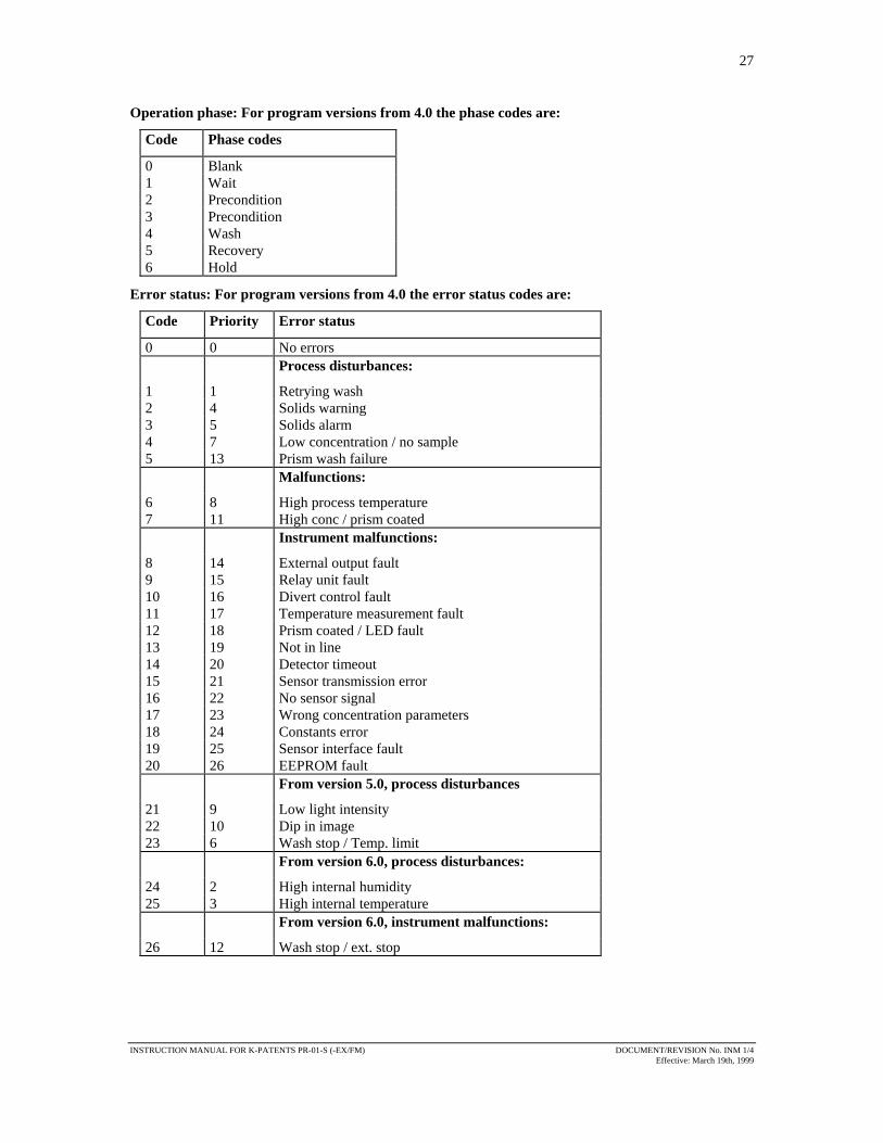
Operation phase: For program versions from 4.0 the phase codes are:
Code
6 8 High process temperature
EEPROM fault
Phase codes
0
7 11
From version 5.0, process disturbances
21
Blank1
High conc / prism coated
9 Low light intensity
Wait2 Precondition
Instrument malfunctions:
8
22 10 Dip in image
3 Precondition
14 External output fault
23 6 Wash stop / Temp. limit
4 Wash
9 15 Relay unit fault
5 Recovery
10 16 Divert control fault
From version 6.0, process disturbances:
24 2
6 Hold
11 17
High internal humidity25
Error status: For program versions from 4.0 the error status codes are:
Code Priority
Temperature measurement fault12
3 High internal temperature
Error status
18 Prism coated / LED fault13
From version 6.0, instrument malfunctions:
0 0 No errors
19 Not in line
Wash stop / ext. stop
Process disturbances:
14 20 Detector timeout
1 1 Retrying wash
15 21 Sensor transmission error
2 4 Solids warning
16 22
3 5
No sensor signal17
Solids alarm4
23 Wrong concentration parameters
7 Low concentration / no sample5
18 24 Constants error
13 Prism wash failure
19 25 Sensor interface fault
Malfunctions:
20 26
26 12
INSTRUCTION MANUAL FOR K-PATENTS PR-01-S (-EX/FM) DOCUMENT/REVISION No. INM 1/4Effective: March 19th, 1999
28
Divert status: The divert status field reports the divert control status in coded form, see Section 10.2.
The codes are:
Code Status
0 divert not activated1 divert failure2 channel A, not operating3 channel B, not operating4 channel A, operating5 channel B, operating
Checksum: The checksum is the arithmetic sum of ASCII codes in columns before the checksum field.For programs until version 3.1 the range is columns 1 to 65. For programs from version 4.0 the range iscolumns 1 to 67. Least significant 7 bits are taken into the sum: the parity bits are zeroed.
Record terminator: The record is terminated with ASCII characters CR (0d hex) and LF (0a hex) to makethe record a text line.
3.8. FUSES
Fuses printed on circuit board PR-7030:
Fuse F1, F2: 5 x 20 mm, T1A (slow) AC Main power protects electronics against wrongprimary voltage
Fuse F3: 5 x 20 mm, T63 mA (slow) 4-20 mA output protection
Fuse F4: 5 x 20 mm, T2A (slow) Secondary main fuse
Fuse F5: 5 x 20 mm, T500 mA (slow) Sensor power protection
Fuse F6: 5 x 20 mm, T500 mA (slow) Serial bus protection
Fuse F7: 5 x 20 mm, T1A (slow) Processor card protection
Note. For a CSA-Certified instrument use only CSA-Certified fuses F1, F2, F4-F7.
INSTRUCTION MANUAL FOR K-PATENTS PR-01-S (-EX/FM) DOCUMENT/REVISION No. INM 1/4Effective: March 19th, 1999
29
4. START UP
4.1. INITIAL CHECK
a. Check that the Serial Numbers of the Sensor and the Indicating transmitter match (Section 2.1).
b. Check wiring and supply voltage (Section 3.6).For intrinsic safe installations, check with Figures12.20...12.22.
c. Press the main power switch to ON position. The three green LEDs (LD1, LD2, LD3) on the PowerSupply card (Figure 6.40) are then turned on.
d. The Normal Display (Figure 2.60) should now appear. The diagnostic message should be "Normaloperation" or if the process pipe is empty "Low concentration/no sample". For any other messageconsult section 6.3.
e. The display should show the current process temperature.
f. TEST value in the display should be in the range 8-248. A value near 248 indicates a clean prism in anempty process pipe.
g. For the concentration reading, see Section 4.2.
h. Press soft key "Display" for additional data (Figure 2.71), like e.g. output in mA. Further data isobtained by soft keys "Optical image" and "System configuration". Return to previous display byRESET key.
i. Measure the output signal. It should agree with the mA display.
j. IMPORTANT: If a prism wash controlled by a Relay Unit is employed, press soft key "Start prismwash" and check the wash sequence. The TEST value should clearly increase (and the concentrationreading decrease) during wash. The "Start prism wash" soft key does not show, if no relay is specifiedas wash relay.
If the initial check is not OK, turn to Chapter 6.
4.2. CALIBRATION CHECK
Wait until normal process conditions occur. The instrument is precalibrated at delivery (DELIVERYDATA SHEET). Hence an on-scale output should be obtained. If not, take a few samples and check thatthe process conditions are normal.
If the diagnostic message is "Normal operation" but the concentration reading is at the wrong level,correction can be entered by the keyboard (Section 5.2).
If the concentration reading is correct, but not the output mA, see Section 5.1.
The damping of the concentration measurement may be increased, e.g. if necessary to get a smootherrecorder track, see Section 2.8. A damping time of 15 seconds is normally the best. WARNING: Avoidoverdamping, the signal should not be insensitive.
4.3. DEMO MODE
The Indicating transmitter can be used as stand-alone for training of keyboard handling. The built-in Demoprogram contains a sensor simulator.
To activate the Demo mode
INSTRUCTION MANUAL FOR K-PATENTS PR-01-S (-EX/FM) DOCUMENT/REVISION No. INM 1/4Effective: March 19th, 1999
30
a. Disconnect the sensor cable (1-7) and all connections to the Serial bus (8-14) from the Indicatingtransmitter.
b. Connect terminal 1 to 8, and terminal 2 to 9, Figure 4.30.
When the Demo mode is active, a small star appears in the top left corner of the display.
Figure 4.30 Demo connection.
INSTRUCTION MANUAL FOR K-PATENTS PR-01-S (-EX/FM) DOCUMENT/REVISION No. INM 1/4Effective: March 19th, 1999
31
5. CALIBRATION
K-Patents Process Refractometer is delivered precalibrated according to the DELIVERY DATA SHEET.Adjustments or change of range can be made by keyboard entry (Sections 5.1 and 5.2). Larger changes ofmeasuring range may require mechanical zero adjustments (Section 5.5). For sensor rangeability, seeSection 5.6.
Field calibration
The final calibration to obtain full accuracy is made by sending data to K-Patents or local K-Patentsrepresentative for calculations (Section 5.3.).
Temperature calibration is explained in Section 5.8.
5.1. OUTPUT CURRENT RANGE SELECTION
It is possible to change the concentration range of the output current, also when the instrument is installedand operating.
Example: To change 4-20 mA = 15 - 25 CONC% to 4-20 mA = 10 - 30 CONC%, key in the sequence
Calibrate/Parameters/Output signals/Current output and then enter Zero = 10 and Span = 20.
Important: This change is useful only if the TEST value is correct over the entire new range, see Section5.6.
5.2. CONCENTRATION CALIBRATION FROM KEYBOARD
The concentration display should be in agreement with laboratory determinations. Deviations can becorrected from keyboard if the diagnostic message is Normal operation. If the TEST display is outside therange 20 - 246 (High concentration or Low concentration messages) mechanical adjustment is needed(Section 5.5).
Off-set adjustment:
A change of the calibration constant Bias influences the CONC% reading the same amount. Key inCalibrate/Parameters/CONC (RI)/Parameters/Bias to read and change the Bias.
Example: If the CONC% display is 26% and the laboratory determination is LAB% = 28%, then a valueBias = 23.456 should be changed to Bias + LAB% - CONC% = 25.456.
Note: The CONC% reading is restricted to positive values even if the mathematical calculation gives anegative value. For a negative CONC% the display shows "0.0". For BIAS adjustment it is useful to knowthe real CONC% value. For this reason the calculated negative CONC% reading is shown in theCalibration branch of the Selection tree, Figure 2.61.
Warning: Never try to change Bias in a day-to-day manner, or week-to-week. Frequent bias changes willincrease the measurement variation, not decrease it.
Amplification adjustment. The size of CONC% changes are directly proportional to the calibrationconstant Gain. The point, where TEST = 128, is not influenced by Gain. From two measurement points thenew Gain can be estimated by the formula Gain*(LAB%1-LAB%2)/(CONC%1-CONC%2). After thechange of the Gain, the Bias has to be determined by a new sample.
The constants Square and Cube are linearity corrections that can be provided by K-Patents, see Section 5.3.
INSTRUCTION MANUAL FOR K-PATENTS PR-01-S (-EX/FM) DOCUMENT/REVISION No. INM 1/4Effective: March 19th, 1999
32
5.3. FIELD CALIBRATION
The most accurate calibration is made under normal process conditions employing the users standardlaboratory determinations of sample concentration. K-Patents provides a FIELD CALIBRATION serviceto optimize calibration constants based on data supplied by the user.
The user should systematically record calibrating data by the CALIBRATION DATA REPORT (last pagein this manual). Each data point consists of:
LAB% Sample concentration determined by the user.
From refractometer display (Section 2.7):
CONC% Measurement in concentration units
TEST Number of photocells on the light side of the optical image(= primary measurement)
TEMP Process temperature measurement in centigrades
Note: A data point is of use for calibration only when the diagnostic message is Normal operation. Do nottake samples during the prism wash. A data point is useful even if the concentration value is outside therange of the output current.
To achieve an accurate calibration the sample has to be taken correctly:
– The sampling valve and the refractometer should be installed in the same place in the process.
– Take the sample and read the display at exactly the same time!
– For hot samples use a tight container (avoid evaporation)
– Run the sample before starting to collect (avoid old sample that has remained in the sampling valve).
A completed CALIBRATION DATA REPORT with 5 - 15 calibration points covering the measurementrange can be sent to K-Patents or local K-Patents representative by fax. A computer analyses of the datawill be made at K-Patents and an optimal calibration data will be faxed to the user.
5.4. BENCH CALIBRATION
The calibration can be checked off-line using Standard RI liquids. The exact procedure is described in aseparate K-Patents brochure No. IV95 “Instrument Verification For ISO 9000 Quality System”. The"Standard RI(25 °C)" display should then show the corresponding value.
The check should be done at room temperature, but the temperature does not have to be exactly 25 °C asthe displayed value is temperature compensated. If the sensor is hot, let it cool down to ambienttemperature.
Standard RI (25 °C) Display: For gain = 0, the indication is 0.0000. For off-set adjustment (like in Section5.1), the bias change has to be multiplied by 100. E.g. If indication is 0.0004 low, add 0.04 to the bias forRI(25 °C).
Standard RI liquids are available from: R.P. Cargille Laboratories, Inc., 55 Commerce Road, Cedar Grove,New Jersey 07009-1289, U.S.A. Phone: 973-239-6633, Fax: 973-239-6096.
INSTRUCTION MANUAL FOR K-PATENTS PR-01-S (-EX/FM) DOCUMENT/REVISION No. INM 1/4Effective: March 19th, 1999
33
A 12 bolttles set of RI liquids are also available at K-Patents with part number PR-2000. The complete setwith 24 bottles of liquids covers the RI range 1.300 - 1.530 as follows:
1.300 - 1.390 Cat. No. 18032
AAA-1/2 Half Set, Int. 0,01 10 liquids
1.400 - 1.450 Cat. No. 18065
AA-1/5 Fifth Set, Int. 0,01 6 liquids
1.460 - 1.530 Cat. No. 1809X (in steps of 0,01)
A-x Std 1/4 fl.oz. (7cc) 8 liquids
Figure 5.40 Sample holder.
Use a sample holder kept in place by a rubber link, Figure 5.40. Then just a few drops of sample areenough. Avoid strong direct light on prism. Sample leakage from holder may give measurement error.Always use repeated measurements for each sample. Sample holders are available at K-Patents (Partnumber PR-5002).
Dispose of used RI-liquids. Do not put liquids back into the bottle after use!
Off-line calibration using process liquid seldom gives reliable results, problems are caused by
– low flow which makes sample to form an unrepresentative film on the prism
– sample evaporation at high temperature or undissolved solids at low temperature giving deviationsfrom laboratory determinations
– an ageing sample which is not representative
Calibration using the process liquid should be made in-line, see Field calibration (Section 5.3).
5.5. MECHANICAL ZERO ADJUSTMENT
A mechanical zero adjustment can be made within the limits given in section 5.6.
The mechanical zero adjustment can be made with the Sensor in-line. To make a mechanical zeroadjustment remove the Image Detector Module according to the instructions in Section 6.8.
Near the tip of the module (Figure 5.50) there is a fiber optics holder (C) and two adjustment screws (Seesection 7, Parts list, Sensor items 9.4 and 9.5). The two screws work against each other in push-and-pullconfiguration. One screw (A) pushes the holder inwards and the other screw (B) pulls the holder outwards.The holder is locked by a combined push and pull force.
INSTRUCTION MANUAL FOR K-PATENTS PR-01-S (-EX/FM) DOCUMENT/REVISION No. INM 1/4Effective: March 19th, 1999
34
To increase the TEST reading move the holder (C) outwards (up in Figure 5.50), to decrease the TESTreading move it inwards (down in Figure 5.50). The output signal is generally a concentration signalinversely proportional to the TEST-reading. To be able to measure higher concentrations, move the holder(C) outwards, to measure lower concentrations move it inwards.
One turn of the adjustment screw corresponds to 45 TEST reading units. As a rule of thumb, one TESTpulse corresponds to 0.2 % concentration. Thus one turn of the screw gives a 9 % concentration change.
Note: After the mechanical zero adjustment, check the optical image, see Section 6.5.
Warning: If the sensor cover is removed, ambient light disturbs the CCD-signal.
Figure 5.50 Mechanical zero adjustment
5.6. SENSOR RANGEABILITY
The Sensor is made in two versions: Probe tip angle 50 degrees and 57 degrees. The value is stamped onthe probe tip.
The rangeability is described in Figure 5.60. for the two sensor versions. The shaded area shows the spanfor a typical mechanical zero setting. By mechanical zero adjustment (Section 5.5) the shaded area can bemoved right (holder moved outwards) or left within the borders of the rectangle. E.g. The 57 degreeversion can measure up to RI 1.530.
If the desired measurement range cannot be achieved with the sensor version in use, then the sensor has tobe exhanged.
The standard span in Figure 5.6 is based on an objective lens focal length f=18. A wider span multiplied by1.8 (f=10) is available, with an accuracy of + 0.0003 R.I.
INSTRUCTION MANUAL FOR K-PATENTS PR-01-S (-EX/FM) DOCUMENT/REVISION No. INM 1/4Effective: March 19th, 1999
35
1.30 1.35 1.40 1.45 1.50 1.55 1.60
50
57
R.I.
400 10 20 30 50 60 70 80 BRIX
Figure 5.60 Sensor rangeability.
5.7. EEPROM PARAMETERS
How to enter the calibration parameters into the non-volatile EEPROM memory is described in Section 2.8.The factory settings are found in the DELIVERY DATA SHEET. Figure 5.70 shows how the microprocessorprogram is using the parameters.
BIASGAINCUBESQUARE
TNMTCOEFFTEMP TCADJ.CONC TCADJ.SQUARE TEMPCO
DAMPINGTEST
TEMP
UNITDECIMALS
ZEROSPANHOLD
UNIT°C / °F
CONC.DISPLAY
OUTPUTmA
TMPC 0TMPC 1
RI-BIASRI-GAINRI-CUBERI-SQUARE
STAN-DARDRIDISPLAY
FIXEDRITEMP.COMP.
TBIAS TEMP.DISPLAY
TEMP °C
DATA SENSORADAPTION
Figure 5.70 Calculation flow diagram.
The ENTER procedure contains a check of the EEPROM parameters format. A number outside the rangelimits cannot be entered. Only if the range limits of a parameter contain a decimal point, the parameter maycontain a decimal point. For some parameters the number of characters is limited (character = digit,decimal point or minus sign).
Indicating transmitter exchange:
If the Indicating transmitter is exchanged, then all parameters and configuration determinations have to bechanged.
INSTRUCTION MANUAL FOR K-PATENTS PR-01-S (-EX/FM) DOCUMENT/REVISION No. INM 1/4Effective: March 19th, 1999
36
Sensor exchange:
To substitute a Sensor by a spare Sensor calibrated for the same range, keeping the Indicating transmitter,the ten constants in the "sensor adaption" zone (Figure 5.70) have to be entered according to the constantsof the spare sensor, see the DELIVERY DATA SHEET. If the Sensor is calibrated for another range (orprocess medium), the Bias, Gain, Square and Cube have to be determined by Field Calibration (Section5.3).
The calibration constants:
– Concentration linearization: Bias, Gain, Square, Cube. Normally a 6 character number (.and -included). Enter from Calibration/Parameters/CONC/Parameters.
– Temperature compensation: TNM, Temp coeff, Temp TC adj, Conc TC adj, Square Temp CO. IfTemp coeff = 0 and TC adj = 0, then there is no temperature compensation. Enter fromCalibration/Parameters/CONC/Parameters.
– Linearization of Standard RI (25°C): RI-Bias/Gain/Square/Cube. The values are specific for eachsensor. Enter from Calibration/Parameters/Standard RI.
– Temperature adjustments: TMPC0, TMPC1 are factory adjusted and specific for each sensor. ForTbias, see Section 5.8. Enter from Calibration/Parameters/Temperature.
5.8. TEMPERATURE CALIBRATION
Normally the process liquid temperature is considerably higher than the ambient. Then the heat lossthrough the Sensor may cause the temperature display to be about 5 °C (9 °F) lower than the processtemperature. This will not impair the measurement, and the difference can be ignored.
If, however, the temperature has to show an absolute correct value, then a bias in °C can be added to thetemperature reading, "Temperature bias".
Note: A change of Temperature bias will cause a small change in the concentration output, due to thetemperature compensation.
INSTRUCTION MANUAL FOR K-PATENTS PR-01-S (-EX/FM) DOCUMENT/REVISION No. INM 1/4Effective: March 19th, 1999
37
6. MAINTENANCE
6.1. REGULAR MAINTENANCE
The need for regular maintenance is minimal, due to the construction with no moving parts, no trimpotsand with a solid-state light source. The following rules apply:
– Keep the sensor head and the Indicating transmitter clean and dry.
– Check that the ambient temperature is not above +45 °C (113 °F). The sensor head should not be toohot to keep a hand on.
– Check that the prism wash works, see Section 8.1.
– Once a year check that the prism surface is smooth and clean. To replace prism or gaskets see section6.7.
– The PR-01-S sensor has an internal moisture detector, except for PR-01-S-EX/FM, see below. Thereading is obtained from the Indicating transmitter display (Key sequence: Display/Sensor Head).Check that reading once a month. An increasing signal indicates condensate forming in the sensorhead (if the process temperature is below ambient) or prism leakage. If the moisture reading exceeds30%, change the drying agent. If the reading exceeds 50%, check the prism seals.
– The intrinsically safe sensor PR-01-S-EX/FM (or earlier versions of PR-01-S) is equipped with amoisture indicator (Figure 6.10). The sectors in the moisture indicator should be light blue. If sector30% is pink, change the drying agent. If sector 40% or 50% is pink, check also the instrument. (It mayindicate prism seal leakage).
– The drying agent is contained in a perforated aluminium case inside the sensor head cover. The dryingagent should appear blue through the window in the aluminium case. Regenerate the drying agent bykeeping the perforated aluminium case in a 130 -150 °C oven for a few hours or dry it with a hot airblower.
Note: Never remove or try to regenerate the moisture indicator (Figure 6.10).
30 40
50
Figure 6.10 The moisture indicator of the PR-01-S-EX/FM sensor.
6.2. DIAGNOSTICS
For a systematic approach to the identification of a faulty component a basic understanding of theoperation is necessary. Read sections 2.3 to 2.8 for general information. Use flow diagram Figure 6.20 forguidance.
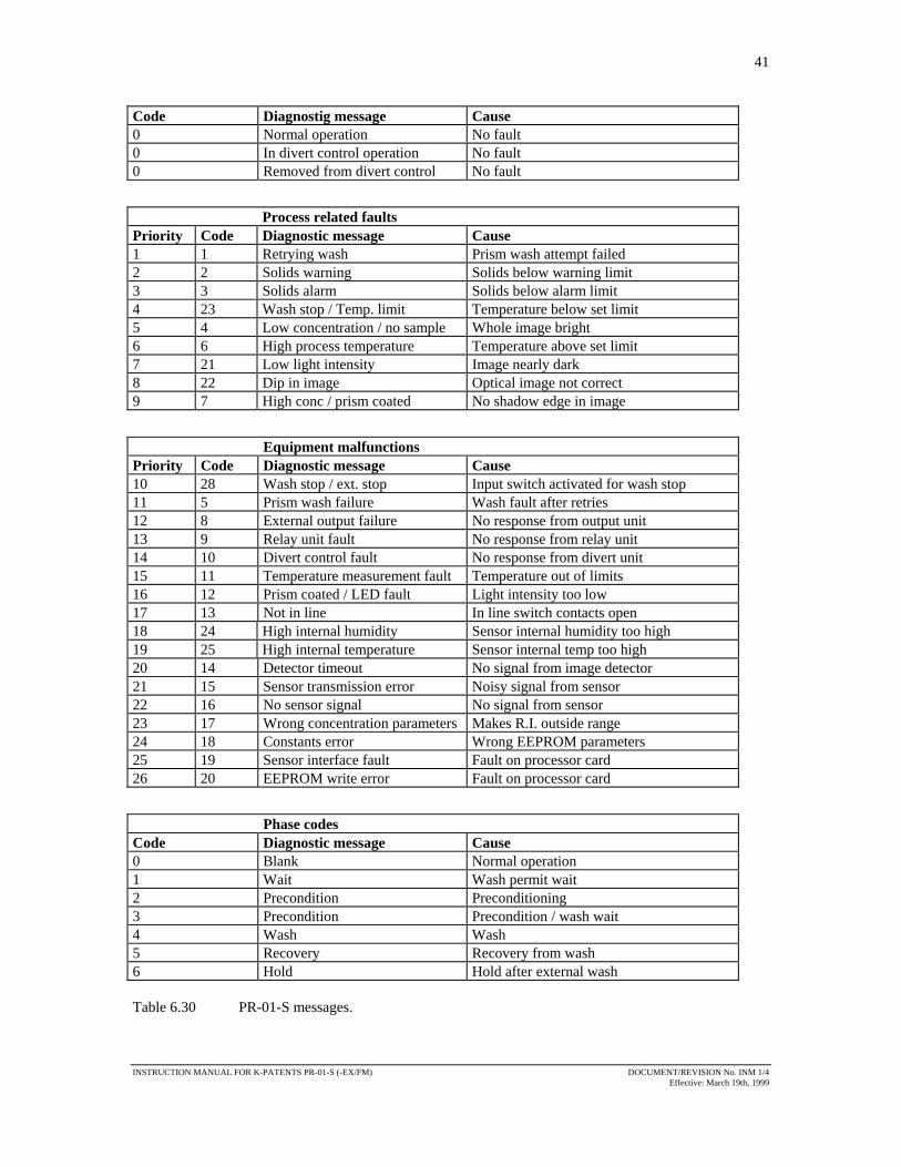
The trouble shooting normally starts with a check of the Diagnostic message (Table 6.30). Remember thata sluggish or irregular output signal can result from unfavourable process flow conditions, section 3.1.
INSTRUCTION MANUAL FOR K-PATENTS PR-01-S (-EX/FM) DOCUMENT/REVISION No. INM 1/4Effective: March 19th, 1999
38
Figure 6.21 gives a general description of the information and power flow between different parts of thetotal system. Section 6.4 gives a complete description of the Indicating transmitter. Figure 6.22 shows thesignals cable. Section 6.5 describes the Sensor and the optical image. Section 6.6 gives the details of thetemperature measurement.
TROUBLE?
ISDISPLAY"NORMALOPERA-TION"
?
SIGNALDRIFTS
UPWARDS?
TROUBLETOLD BYDISPLAYMESSAGE
PRISMCOATED,NEEDSCLEANING
FOLLOWMANUALSECTION6.3
CHECK-FLOWSECTION 3.1
-PRISM WASHSECTION 8.1
MAKE A FIELDCALIBRATIONSECTION 5.3
NO
YES
YES
NO
Figure 6.20 Diagnostics guide.
INSTRUCTION MANUAL FOR K-PATENTS PR-01-S (-EX/FM) DOCUMENT/REVISION No. INM 1/4Effective: March 19th, 1999
39
Figure 6.21 Information and power flow. For intrinsically safe system, see Figure 12.50.
1 1
4 4
7
2 2
5 5
8
3 3
6 6
109
RED
RED
RED
RED
BLUE
BLUE
BLUE
BLUE
SEN+
+24V
SEN-
0V
GND
GNDPGND
1
4
2
5
3
67
Indicating transmitter Plug
WHITE
BLACKBLUE
BROWN
Cable
Image Digitizer
Figure 6.22 Cable signals. For intrinsically safe systems, use Figure 12.22 (field wiring) and Figure12.53 (internal wiring).
INSTRUCTION MANUAL FOR K-PATENTS PR-01-S (-EX/FM) DOCUMENT/REVISION No. INM 1/4Effective: March 19th, 1999
40
6.3. DISPLAY MESSAGES
The diagnostic messages and the phase codes are listed in Table 6.30. The diagnostic messages are listedby increasing priority. E.g. if we simultaneously have “Temp measurement fault” condition and "No sensorsignal" condition, the display message will be "No sensor signal".
NORMAL OPERATION:
If the CONC% display is not according to specifications, take samples and use Calibration Data Report,Section 5.3. Also check that the prism surface is clean.
PRECONDITIONING:
Shown when the preconditioning valve is activated by the Relay Unit, Chapter 9.0.
WASH:
Shown when the prism wash valve is activated by the Relay Unit. The concentration output is locked (if theHOLD function is active). The HOLD function can be inactivated from the keyboard, (Section 2.8). Theconcentration display is never locked, but a large "WASH" will flash when the wash starts.
RECOVERY:
Shown during the time delay after end of prism wash when the concentration output is still locked.
HOLD:
Caused by input switch closure, when the switch has been configurated as a Hold switch, Section 2.8.
HIGH INTERNAL HUMIDITY:
Caused when humidity inside the sensor is higher than 50%.
Action: Remove the sensor from the process line and check it, see Section 6.1.
HIGH INTERNAL TEMPERATURE:
Caused when the temperature inside the sensor is higher than 60 °C (140 °F).
Action: Improved air-cooling is recommended, see Section 3.1.
WASH STOP / TEMP. LIMIT:
Caused when the Wash stop is active and the process temperature is below temperature limit, Section 9.2. Themessage is shown until wash succeeds or the RESET key is pushed.
LOW CONCENTRATION/NO SAMPLE:
Probably caused by exceptionally low concentration or empty process pipe.
Action: If sample determination indicates normal concentration, then check optical image, Section 6.5,decision according to Figure 6.54.
INSTRUCTION MANUAL FOR K-PATENTS PR-01-S (-EX/FM) DOCUMENT/REVISION No. INM 1/4Effective: March 19th, 1999
41
Code Diagnostig message
8 22 Dip in image Optical image not correct
Sensor internal humidity too high19 25
3 Precondition Precondition / wash wait
Cause0
9 7
High internal temperature Sensor internal temp too high
4 Wash Wash
Normal operation No fault
High conc / prism coated No shadow edge in image
20 14 Detector timeout
5 Recovery
0 In divert control operation No fault
Equipment malfunctions
No signal from image detector21 15
Recovery from wash6 Hold
0 Removed from divert control No fault
Priority Code
Sensor transmission error Noisy signal from sensor
Wrong concentration parameters Makes R.I. outside range
1 1 Retrying wash Prism wash attempt failed
12 8 External output failure
25
2 2 Solids warning Solids below warning limit
No response from output unit13 9
19 Sensor interface fault Fault on processor card
3 3
Relay unit fault No response from relay unit
26 20 EEPROM write error
Solids alarm Solids below alarm limit
14 10 Divert control fault
Fault on processor card
4 23 Wash stop / Temp. limit Temperature below set limit
No response from divert unit15 11
Phase codes
5 4
Temperature measurement fault Temperature out of limits
Code Diagnostic message Cause
Low concentration / no sample Whole image bright
16 12 Prism coated / LED fault
0 Blank
6 6 High process temperature Temperature above set limit
Light intensity too low17 13
Normal operation1 Wait
7 21
Not in line In line switch contacts open
Wash permit wait2
Low light intensity Image nearly dark
18 24 High internal humidity
Precondition Preconditioning
Diagnostic message Cause
22 16 No sensor signal
Table 6.30 PR-01-S messages.
Prism wash failure Wash fault after retries
24 18 Constants error Wrong EEPROM parameters
INSTRUCTION MANUAL FOR K-PATENTS PR-01-S (-EX/FM) DOCUMENT/REVISION No. INM 1/4Effective: March 19th, 1999
42
HIGH PROCESS TEMPERATURE:
The process temperature exceeds the "High temperature limit" set from keyboard after Calibrate/Temperature.This alarm can be enabled/disabled. The cause may be abnormal process conditions or a leaking prism washsteam valve.
LOW LIGHT INTENSITY:
The shadow edge is still detected, but the light intensity is low, see Figure 6.54. This message probablyindicates onset of prism coating.
DIP IN IMAGE:
Inspect the optical image for irregularities. Missing or low pulses in the light area may be caused by a speck ofdust on the CCD window or optical fiber end.
**WASH STOP / EXT. STOP **:
Caused if an input switch is activated for external wash stop and the corresponding input switch is connected,Section 2.8.
HIGH CONC/PRISM COATED:
Indicates prism coating.
Action: Clean the prism surface. Use a strong solvent like nitric acid. If message persists, check opticalimage, Section 6.5, decision according to Figure 6.54.
Note: May be caused by exceptionally high concentration.
** EXTERNAL OUTPUT FAULT **:
The External Output unit (Section 10.1) did not acknowledge the transmission. Serial bus or Output unitfailure. The Output unit may also be disconnected.
To prevent this message when the Output unit is disconnected, key in Calibrate/Parameters/Outputsignals/External output/Source and select: "Not defined".
** RELAY UNIT FAULT **:
The Relay unit (Chapter 9.) did not acknowledge the transmission, Serial bus or Relay unit failure. Maybethe Relay unit is not connected.
To prevent this message when the Relay unit is disconnected, key in Calibrate/Parameters/Relays/Relayunit and select "Not defined" for each relay.
** TEMP MEASUREMENT FAULT **:
Indicates that the temperature value reported by the sensor corresponds to a value below -50 °C or above+250 °C by a margin of 10 %. Probably temperature sensor failure, see Section 6.6.
If "Temp. measurement fault" the temperature will be set to TNM (one of the CONC(RI) parameters). Thisvalue is then also used in the temperature compensation, which means that the output will be reasonableeven at temperature measurement failure.
Action: Change temperature sensor.
INSTRUCTION MANUAL FOR K-PATENTS PR-01-S (-EX/FM) DOCUMENT/REVISION No. INM 1/4Effective: March 19th, 1999
43
** PRISM COATED/LED FAULT **:
Light intensity too low, probably due to coating.
Action: Clean the prism surface. Use a strong solvent like nitric acid. If message persists, check opticalimage, Section 6.5, decision according to Figure 6.54.
** DETECTOR TIMEOUT **:
The fault is in the sensor, Section 6.5.
No signal from the Image detector card received by the Image digitizer card. Probably CCD-element orImage detector card failure. The 15 V supply to the Image detector card may be incorrect due to a wrongposition of the main power switch, see Section 3.6.
Action:
1. Check the position of the main power switch.
2. Change the Image detector card.
** SENSOR TRANSMISSION ERROR **:
The signal from the Sensor to the Indicating transmitter is irregular. The sensor transmission has overrun orthere is a checksum error on the received message. Error is caused by noise in the sensor transmission.
** NO SENSOR SIGNAL **:
There is a sensor signal timeout. No signals have arrived during the 800 ms measurement interval(normally about 5 scans). Probably the interconnecting cable is not connected properly.
** WRONG CONCENTRATION PARAMETERS **:
This occurs only if the output unit is selected to be RI (x °C). Then this message occurs if CONC(RI)parameters give a value below 1 or above 2. To reset this message, either key in correct CONC(RI)parameters or change the concentration unit (Select Calibrate/Parameters/CONC(RI)/Unit).
** CONSTANTS ERROR **:
There are constants in the EEPROM outside allowed range. This error stops the measurement process.
Action: Switch power OFF/ON. Then one of two alternatives will occur
1. If the EEPROM has been changed, or the program upgraded:** Constants are not available **Press ENTER to load default settingsPress RESET not to change.
2. If only some constants are wrong:** There are erroneous constants **The bad constants can be set to default settingPress ENTER to correct bad constants
** SENSOR INTERFACE FAULT **:
Error on the processor card in the Indicating transmitter (Section 6.4): The sensor interface processor(87C51) did not respond properly. Probably failure of this processor.
Action: Change the processor card.
INSTRUCTION MANUAL FOR K-PATENTS PR-01-S (-EX/FM) DOCUMENT/REVISION No. INM 1/4Effective: March 19th, 1999
44
** EEPROM WRITE ERROR **:
Error on the processor card: The EEPROM did not write constants correctly. Probably component failure.
Action: Change the processor card.
No message: Measure the mA output signal. If this is OK, then the display is probably faulty.
Note. Ambient temperature above specifications may dim the display.
6.4. INDICATING TRANSMITTER
Before investigating the Sensor, it is advisable to make sure that the Indicating transmitter is working. TheIndicating transmitter can be tested separated from the Sensor by the following procedure:
– Power off– Disconnect cable to sensor– Power on
Then the diagnostic message should be
"** No Sensor signal **". Any other message indicates fault in the Indicating transmitter.
The Demo mode, Section 4.3. Disconnect all connections to terminals 1 - 14, and make connection as inFigure 4.30. Then the Serial bus output will work as a sensor head simulator, and the whole Processor cardwill be checked, see the block diagram Figure 6.42.
Power supply card
The Power supply card is described by Figure 6.40 component lay-out and Figure 6.41 circuit diagram.
The following DC powers are supplied by the card:
1. +5V to Processor card. Should be 5V ± 5 %. Typical load about 350 mA, should be below 500 mA.Indicated by the green LED LD3, see Figure 6.40.
2. +24V to Sensor. Typical value 25V ± 10 %, indicated by the green LED LD2.
3. +24V to serial bus, to supply accessory units, as the Relay unit, Chapter 9. Typical value 25 V ± 10 %,indicated by the green LED LD1.
The Test point "0V", see Figure 6.40, is also the 0V at the Processor Card, in the Sensor and in the serial busto accessory units.
INSTRUCTION MANUAL FOR K-PATENTS PR-01-S (-EX/FM) DOCUMENT/REVISION No. INM 1/4Effective: March 19th, 1999
45
Figure 6.40 Power supply card component lay-out.
INSTRUCTION MANUAL FOR K-PATENTS PR-01-S (-EX/FM) DOCUMENT/REVISION No. INM 1/4Effective: March 19th, 1999
46
Figure 6.41 Power supply card circuit diagram.
Processor card
The function of the Processor card is described by the block diagram Figure 6.42 and the component lay-out Figure 6.43.
INSTRUCTION MANUAL FOR K-PATENTS PR-01-S (-EX/FM) DOCUMENT/REVISION No. INM 1/4Effective: March 19th, 1999
47
When measuring voltages on the Processor card it is important to remember that some parts aregalvanically separated form each other, see Figure 6.42. It is essential to use the right ground formeasurement:
– TP 0V for processor, and also for DC power supply, Serial bus and Sensor.
– TP is 4-20 mA current loop groundCLGND
– TP SGND is RS-232/RS-485 serial output ground
– TP COM is switch input common terminal
Diagnostic LEDs
Two LEDs on the Processor card indicate the CPU (80C186) activity, see Figure 6.43:
LED D3 is lit when the processor is running
LED D4 is lit during interrupt service
Both LEDs should show a blinking light if the processor is working normally. Four rythms with differentintervals are overlapping: 10 ms clock, 150 ms new sensor data, 800 ms new value calculation, 1 s timercount. The most obvious rythm is th 800 ms; first a short D4 blink, then a 200 ms D3 flash.
Processor startup errors
The processor hardware is checked on startup. The startup failures are announced as blinking codes on theLED D3. The error code is 1 to 5 blinks on D3 with D4 dark. The error code is the following:
– 1 blink: The chip select unit on the CPU chip (80C186EB) is faulty.
– 2 blinks: The CPU failed the register test. The CPU chip is faulty.
– 3 blinks: The RAM memory failed the address uniqueness test. The memory or its bus interface isfaulty.
– 4 blinks: The RAM memory failed the pattern test. There is a bad RAM chip.
– 5 blinks: The code in ROM failed the CRC check. The code is protected with a CRC check. The ROMchip or program pattern in it is faulty.
INSTRUCTION MANUAL FOR K-PATENTS PR-01-S (-EX/FM) DOCUMENT/REVISION No. INM 1/4Effective: March 19th, 1999
48
DISPLAY
KEYBOARD
DISPLAYCONTROLLERCARD
CPU80C186
SRAMCPU87C51
4-20 mAOUTPUT
SERIALBUS
SERIALOUTPUTRS-485/232
SENSORINTERFACE
SENSORDATA
SWITCHES
PROCESSORCARD
SRAM
EPROM
EEPROM
Figure 6.42. Processor card block diagram.
INSTRUCTION MANUAL FOR K-PATENTS PR-01-S (-EX/FM) DOCUMENT/REVISION No. INM 1/4Effective: March 19th, 1999
49
Figure 6.43 Processor card component lay-out.
Display controller card
The Display controller card has the components surface mounted, and it should be considered as one part.
Keyboard
The Keyboard switch matrix is given by Figure 6.46.
INSTRUCTION MANUAL FOR K-PATENTS PR-01-S (-EX/FM) DOCUMENT/REVISION No. INM 1/4Effective: March 19th, 1999
50
A B C D
7
4
1
0
8
5
2
.
9
6
3
- RESET
To processorcard P3
1
10
ENTER
Figure 6.46 Keyboard switch matrix.
Transformer
For transformer colour code, see Figure 6.47. The leads are connected to the following Power cardterminals (compare to Figure 6.40):
black
gray
brown
blue
P1
P2
S1
white
white
yellow/green
Static Shields
2 x 110 V50-60 Hz
24 V 50 VAUo = 26.6 V
yellow
34
3537
38
36
32
33
42
Figure 6.47 Transformer.
6.5. SENSOR CHECK
Study Figure 6.50 to get a basic understanding of how the Sensor works.
Select Calibrate/Optical image from the Normal Display (Figure 2.60). The screen (Figure 6.51) containsnow all raw data from the Sensor including the signals from each photo cell, i.e. the raw video signal. Thisdiffers from the Optical image, Figure 2.72, selected through the "Display" key.
The video signal describing the optical image should look like Figure 6.51. In that case the Sensor is OK,and it should not be touched. If the concentration output does not agree with laboratory values, a Fieldcalibration (Section 5.3) should be done.
INSTRUCTION MANUAL FOR K-PATENTS PR-01-S (-EX/FM) DOCUMENT/REVISION No. INM 1/4Effective: March 19th, 1999
51
The video signal can also be measured directly by an oscilloscope. Use an oscilloscope with a 10 MOhmprobe (10x) in AC mode. Connect the signal ground to TP 0V, and the channel to TP4, see Figures 6.52and 6.50. The duration of one image is 3 ms. The voltage amplitude is 2.5 - 3.7 V corresponding toIndicating transmitter display 0 - 255.
Figure 6.50 Sensor information and power flow.a) Standard sensor. b) Intrinsically safe sensor.
Figure 6.51 Optical image and raw data.
INSTRUCTION MANUAL FOR K-PATENTS PR-01-S (-EX/FM) DOCUMENT/REVISION No. INM 1/4Effective: March 19th, 1999
52
Raw data explanations:
RMN, RMX: Minimum and maximum of the raw video signal. This signal is calculated onthe Processor card from the video signal. The scale is 0 - 255, correspondingto full scale on display.
LED: The LED current control signal on a scale 0-255 corresponding to 0 -8 mA.This is the current control signal from the Processor, and not an actualmeasurement of the LED current. The red light of the LED can be seendirectly, Figure 6.80. If the operation is correct, the displayed LED valueshould be above 20 and below 200.
Scans: Number of optical images during one calculation cycle, typically 3 to 4. Thescan pulses (with 5 V amplitude) can be measured at TP 3 (Figure 6.50).
A/D: This refers to the temperature measurement, Section 6.6.
Sts: Sensor status bits. Should be "00h" for a standard and Intrinsically Safesensor. Status "01h" indicates "Detector timeout".
HT: Sensor head temperature sensor reading. This value is used in calculating theactual Sensor head internal temperature.
HH: Sensor head humidity sensor reading. The actual relative humidity in theSensor is calculated from HH and HT.
Sensor faults:
Sensor faults can be distinguished by the following indications:
The diagnostic message ** No sensor signals **:
The fault may be in the single path from Image digitizer to the interconnecting cable to theProcessor card, see Figure 6.22. If the signal path is OK, then the Image digitizer does not work.Check the 24 V and the 5 V supply to Processor card, Figure 6.52. If the supply is OK, change theImage digitizer card.
The diagnostic message ** Detector timeout **:
The scan pulses (Figure 6.50) are missing at TP 3 (Figure 6.52). Check the 15 V supply to theImage detector card, Figure 6.52. If the 15 V supply is OK, but the sync signal TP2 is absent, thenchange the Image detector card. The sync signal is similar to the video signal but the pulseamplitude is constant. Check also the main power selection switch position, see Section 3.6.
A way to check the function of the Sensor is to place an opaque screen before the CCD-element, see arrowmarked screen in Figure 6.50. When the screen blocks the light to the photocell, the video pulses shoulddecrease. When the Max value drops below 200, the LED control signal should increase, which in turnshould make the LED brighter.
If a light e.g. from a flashlight is directed on the screen to illuminate the photocells, then the video signalshould increase, the LED control should decrease and the LED should get dimmer.
Scaled image:
The following display is the scaled image, Figure 6.53. The optical image is now modified mathematically.The following information is provided (where the numbers refer to Figure 6.53):
INSTRUCTION MANUAL FOR K-PATENTS PR-01-S (-EX/FM) DOCUMENT/REVISION No. INM 1/4Effective: March 19th, 1999
53
a)
b)
Figure 6.52 Sensor electronics test points.a) Standard transmitter. b) Intrinsically safe.
INSTRUCTION MANUAL FOR K-PATENTS PR-01-S (-EX/FM) DOCUMENT/REVISION No. INM 1/4Effective: March 19th, 1999
54
Figure 6.53 Scaled optical image.
Right curve OK (above 1)? Yes/No
1. TEST: The calculated TEST value, range 8...248. Indicated by a dotted vertical line.
For measurement with a normal sample, all answers should be "Yes".
A message "Dips in image" appears if the optical image is irregular.
T: indicates the process temperature, to facilitate field calibration
2. Endp: the value of the rightmost point in % of span.
3. L): A measure of the left side curvature of the optical image.
4. R(: A measure of the right side curvature of the optical image.
A zero curvature indicates a straight line. Both curvature values are defined as positivefor an image as Figure 6.53.
5. HT: Sensor head internal temperature in °C.
6. HH: Sensor head internal relative humidity in %RH.
7. An L-shaped corner mark. For a clean prism in air the optical image should form asmooth hill and be above the corner mark.
Slope:
This display shows the slope curve of the optical image. At the TEST value, the SLOPE curve should havea sharp dip. The following additional values are given:
Max: The filtered value of the maximum light intensity RMX of the raw data(Figure 6.51).
Slope: The absolute value of the slope curve dip at TEST. The value of Slopemust be above 1 to be acceptable.
Image diagnostics:
This display lists the critical values for TEST acceptance according to the image analyzer decision rules inFigure 6.54.
Max intensity OK (above 100)? Yes/NoEndpoint below 75 %? Yes/NoImage below corner? Yes/NoSlope OK (above 1)? Yes/NoLeft curve OK (above 1)? Yes/No
INSTRUCTION MANUAL FOR K-PATENTS PR-01-S (-EX/FM) DOCUMENT/REVISION No. INM 1/4Effective: March 19th, 1999
55
MAX BELOW50 ?
MAX BELOW100 ?
ENDPOINTBELOW 75 %
?
DIPS ?
DIPS ?
SLOPEABOVE 1
?
SLOPEABOVE 1
?
LEFT CURVEABOVE 1
?
RIGHT CURVEBELOW 0
?
DIPS IN IMAGE
LOW INTENSITY
HIGH CONC/PRISM COATED
TEST=8
IMAGE BELOWCORNER
?
TEST=248
LOW CONC/NO SAMPLE
RIGHT CURVEABOVE 1
?
PRISM COATED/LED FAULT
TEST=8
NO
NO
NO
YES
YES
YES
YES
YES
NO
NO
YES
YES
YES
YES
NO
NO
NO
NO
NO
YES
YES
NO
Figure 6.54 Image analyzer decision rules.
INSTRUCTION MANUAL FOR K-PATENTS PR-01-S (-EX/FM) DOCUMENT/REVISION No. INM 1/4Effective: March 19th, 1999
56
6.6. TEMPERATURE MEASUREMENT
The temperature is measured by a Pt100 platinum resistance element, see Figure 6.52 and also Section 7.1,Sensor parts, item 10. The Sensor raw data (Section 6.5) gives the A/D value, which refers to thetemperature A/D converter: 0 - 1023 corresponds to 1.8 - 3.0 V corresponding to -75 °C .. 300 °C.
The temperature bias calibration was treated in Section 5.8. The temperature correction parameters TMPC0and TMPC1 are specific for the Image digitizer card, not for the Pt100 element.
To check the temperature measurement, the Pt100 element can be disconnected from the terminal L4, andsubstituted by a Pt100 calibrator. Alternatively, terminal 3 and 2 are connected by a jumper, and 2 and 1 bysuitable resistors, e.g. 100 Ohm for 0 °C and 138.5 Ohm for 100 °C.
6.7. PRISM GASKET REPLACEMENT
Prism dismounting
If the prism surface has been damaged or if the prism seal leaks the prism has to be dismounted:
Remove the sensor head from process and wash thoroughly with warm water. Dry completely e.g. bycompressed air.
Open the two screws (Figure 6.70).
Figure 6.70 Prism mounting.
Prism mounting with Kalrez gaskets
1. Clean the seat carefully. Check that there is absolutely no dirt or dust on the sealing surfaces aroundthe holes and that they are smooth. The prism must have clear and clean surfaces. Clean with e.g.alcohol. Do not touch the sides to the seals after cleaning.
2. Check that the support rings are undamaged. Push the support rings into the holes (Figure 6.71). Therings should fit snugly. Make absolutely sure that the rings are below the surrounding surface (d inFigure 6.71). If a ring is not below the surface, then remove and check that the hole is clean andsmooth.
INSTRUCTION MANUAL FOR K-PATENTS PR-01-S (-EX/FM) DOCUMENT/REVISION No. INM 1/4Effective: March 19th, 1999
57
d
SUPPORT RINGPRISMKALREZ GASKETSENSOR BODY
Figure 6.71 Mounting of Kalrez gaskets.
3. Always use new gaskets. Clean the gaskets with cleansing spray. Mount the Kalrez gaskets and putthe prism in place. Slide the prism lightly in the groove in both directions (± 1 mm). This helps thegaskets to settle in the right position.
4. Put prism holders and screws in place. The teflon or compression pads should be carefully fittedbetween the prism and the prism holders. No part of the compression pads should be between theprism holder and the refractometer body. Tighten the screws alternatingly in small steps. Trim excessteflon with a razor blade.
5. Tighten the screws with torque wrench to 10 Newton meters.
6. Inspect the gasket contact surfaces through the prism. They should form regular concentric ringsaround both holes (Figure 6.72). The rings should have the same size.
7. If the contact surfaces do not look good loosen the screws and start again from the beginning.
Figure 6.72 Kalrez gaskets seen through the prism
PRISM
GASKETS
INSTRUCTION MANUAL FOR K-PATENTS PR-01-S (-EX/FM) DOCUMENT/REVISION No. INM 1/4Effective: March 19th, 1999
58
Prism mounting with teflon gaskets
Teflon gaskets are mounted the same way as Kalrez gaskets. Do not handle the teflon gaskets with metaltools like pliers or tweezers.
False leakage
Sometimes process liquid can be seen behind the prism, Figure 6.73. This is normal and does not indicatethat the prism gaskets are leaking. Only the round areas inside the prism gasket rings are sealed from theprocess liquid. Thus leakage is indicated only if process liquid is seen in the area inside the rings.
Figure 6.73 False leakage.
6.8. SENSOR DISASSEMBLY
FALSELEAKAGE
Cover
Open the clamp using a 11 mm wrench. Lift cover carefully, the O-ring seal causes some friction.
Image digitizer card
Remove the Image Digitizer Card, Figure 6.52. Note that all connectors have latches. The color code forthe terminal strip is given by Figure 6.52. Do not touch any other screw than A in Figure 6.80 and B inFigure 6.81.
Image detector module
Remove Screw A, Figure 6.80. Then the holder can be removed. Gently pull the module out. Be carefulnot to pull the Image detector card. Pull from the back of the module body. At assembly note thealigning pin. Do not touch the screws G or F, because they fix the Image detector card with the CCD-element for receiving optical image correctly from the optics inside of the module.
Light source module
Remove Screw B, Figure 6.81. Then the module can be pulled out. (The hole C should always be empty).The emitter assembly is locked by screw D and can be removed from the module.
Temperature sensor
Use fingers to turn the Temperature Sensor (Fig. 6.81) counter clockwise.
INSTRUCTION MANUAL FOR K-PATENTS PR-01-S (-EX/FM) DOCUMENT/REVISION No. INM 1/4Effective: March 19th, 1999
The optical modules can be tested separately. Remove the module and reconnect to the Image digitizercard.
Light source module
The red light should be seen reflected from the mirror at the tip of the module. This light should focus at a10 mm distance from module.
INSTRUCTION MANUAL FOR K-PATENTS PR-01-S (-EX/FM) DOCUMENT/REVISION No. INM 1/4Effective: March 19th, 1999
60
6.10. LED CURRENT ADJUSTMENT
The LED current is sensitive to the lenght of the light source module. With high LED current controlsignals (above 150 with clean prism in air or above 200 in process) the lenght of the module can beadjusted to decrease the current.
Note. The sensor should be checked first before adjusting the light source, See Sections 6.5 - 6.9.
Consult K-Patents or local K-Patents representative, if you are not familiar with the sensor check.
The length can be adjusted as follows:
– Remove the screw on the tightening ring in the middle of the module.– Loosen the tightening ring.– Rotate the module pipe one full turn to make the module shorter or longer.– The LED current control signal decreases or increases as a result of modifying the length.– The correct length of the module is the one that gives the lowest LED value for clean prism in air.
INSTRUCTION MANUAL FOR K-PATENTS PR-01-S (-EX/FM) DOCUMENT/REVISION No. INM 1/4Effective: March 19th, 1999
61
7. PR-01-S PARTS LISTS
1 Flange DIN 2656, PN 25, DN 80 (AlternativelyANSI B16.5 3" RF 150 psi or JIS 10 K 3B)
7.1. PROBE
PR-01-S(-EX) PROBE
2.2 2
Item Pcs. Part No.
Screw M6 x 30 DIN 912 SS 316L2.3
Description
2 Washer M6 DIN 125 SS 316L
1. 1
Earth screw M6 x 10 DIN 933 A4 (added)2.5
Probe with Sandvik clamp FCL-316L-88,9-S-TPN25
1.1 1
1 Plug IS07 PN8 1/4" AISI 316 for Integral nozzleinlet
INSTRUCTION MANUAL FOR K-PATENTS PR-01-S (-EX/FM) DOCUMENT/REVISION No. INM 1/4Effective: March 19th, 1999
65
8. PRISM WASH SYSTEMS
Three alternatives of prism wash systems can be provided:
– Steam wash with integral nozzle, Section 8.2.– High pressure water with integral nozzle, Section 8.3.
There is an own prism wash nozzle for Isolation and Retractor Valve HIMP-2 for LPH sensor, see Section11.
8.1. PRISM COATING
– Abnormally high concentration reading or upward CONC% drift.– Low TEST values, even TEST = 8.– High LED current (press Calibrate/Optical image), especially LED = 255 (max) (See Section 6.5).– Prism wash (e.g. by press Start prism wash) does not increase the TEST value the appropriate amount:
For steam wash TEST should be close to 248; for water wash close to the TEST value for water.
In most of the applications the prism will keep clean, but if coating occurs, check the following:
– Sensor mounted correctly in respect to flow direction (arrow on sensor head).– Sufficient flow velocity, Section 3.1.– A temperature difference between process fluid and sensor probe may cause coating. This may happen
for small flows if the thermal insulation is inadequate. In some cases it helps to insulate also theconnection flange, Figure 3.10.
If there is a coating problem, it is recommended to try to increase the flow velocity, e.g. by installing a pipeportion with smaller diameter. If this cannot be done, the prism should be automatically washed at regularintervals, e.g. by steam or hot water.
A prism wash nozzle (Sections 8.2-8.4) can be useful also in cases without coating problems, e.g. to cleanthe prism after a process stop using a manual wash valve.
8.2. PRISM WASH WITH INTEGRAL STEAM NOZZLE
Prism wash with integral steam nozzle is for use in applications where steam can remove coating from pipelines. For other applications see Sections 8.3 and 8.4. The integral nozzle is mounted on the sensor head(Figure 8.21).
Integral steam nozzle (HPS) can be equipped for a standard length sensor or a long probe sensor withstandard insertion length (LPS) and with the following process connections:
– Sandvik L-clamp, 80 mm– ANSI-flange 150 lbs– DIN flange 2556, PN25, DN 80– JIS flange, 10 K 80A
– Steam and water wash for flow cell mounting, Section 8.4.
In most of the applications the prism wash is not necessary. However, installing the wash nozzle shouldalways be considered.
A prism wash nozzle (Sections 8.2, 8.3, 8.4) can be useful in cases where normally no prism coatingoccurs, e.g. to clean the prism after a process stop using a manual wash valve. Washing can also be usedfor operational check (output signal decreases during wash) or as a part of maintenance schedule.
Deposit build up on the prism surface disturbs measurement. Look out for the following indications ofcoating:
INSTRUCTION MANUAL FOR K-PATENTS PR-01-S (-EX/FM) DOCUMENT/REVISION No. INM 1/4Effective: March 19th, 1999
66
The earlier mentioned sensors are equipped with an integral nozzle connection (HPY) as a standard. Anintegral steam nozzle can be easily fitted afterwards, if required.
The Figures 8.22 and 8.23 show recommended components for a prism wash system with integral steamnozzle. In Figure 8.22 the Relay unit PR-7080 is used for connections. In Figure 8.23 the Wash controlrelay-unit -WR is used for connections, see Chapter 9 for Relay units. The components are provided by K-Patents. The steam line should be equipped with a check valve (Figures 8.22 and 8.23). If the processmedium solidifies at ambient temperature, the check valve should be insulated (Figure 3.10). A condensatetrap should be used to keep the steam line hot (Figures 8.22 and 8.23).
The Relay unit (Section 9) is used to drive the wash valves, see Figure 8.51. Configuration of the Relayunit is made from Indicating transmitter keyboard, see Section 9.2.
Alternatively, an external timer can be used. The timer should be equipped with extra contact which is keptclosed during prism washes. To lock the output signal (see Section 2.8), connect the extra contact to aswitch input in the Indicating transmitter (Figure 3.64).
Note. Do not connect the extra contact to external voltage.
For recommended wash pressures and times see Section 8.5.
Note. In Intrinsically Safe system solenoid valves are mounted in the safe area and the pneumaticvalves in hazardous area.
INSTRUCTION MANUAL FOR K-PATENTS PR-01-S (-EX/FM) DOCUMENT/REVISION No. INM 1/4Effective: March 19th, 1999
67
Figure 8.21 Mounting of integral steam nozzles with DIN, JIS, ANSI and Sandvik connections.
INSTRUCTION MANUAL FOR K-PATENTS PR-01-S (-EX/FM) DOCUMENT/REVISION No. INM 1/4Effective: March 19th, 1999
68
Figure 8.22 Mounting summary of integral prism wash system for steam with relay unit PR-7080.
INSTRUCTION MANUAL FOR K-PATENTS PR-01-S (-EX/FM) DOCUMENT/REVISION No. INM 1/4Effective: March 19th, 1999
69
Figure 8.23 Mounting summary of integral prism wash for steam with wash control relay unit -WR.
INSTRUCTION MANUAL FOR K-PATENTS PR-01-S (-EX/FM) DOCUMENT/REVISION No. INM 1/4Effective: March 19th, 1999
70
8.3. PRISM WASH WITH INTEGRAL HIGH PRESSURE WATER NOZZLE
Integral high pressure water prism wash is recommended to be used in applications where conventionalwash (Section 8.2) is insufficient to remove coating. It can be used e.g. in the measurement of starch, beerworth, green liquor in the wood pulp industry or direct after the evaporation in the sugar industry.
The Figures 8.30 and 8.32 describe the recommended components for a prism wash system with integralhigh pressure water nozzle. The components can be supplied by K-Patents.
For recommended wash pressures and times, see Section 8.5.
Note the following in the high pressure wash system. Numbers refer to part numbers in Figure 8.30 (notedifferent numbers in Figure 8.32):
Part No. 2 Integral water wash nozzle (HPN) built on a sensor which has a Sandvik clamp or aflange connection.
Part No. 6 For mounting a flow cell see Section 8.4.
Part No. 7 Check valve
Part No. 8 It is recommended to mount a filter for the water inlet before the high pressure pump.Recommended filter size is 0.15 mm and recommended flow rate above 10 liter/minute.
Part No. 12 High pressure pump. The pump should be able to keep a pressure of 100 bar for a 1.25mm (0.05 in) diameter nozzle.
Warning! Pressure increase can occur in a closed pipe section when the high pressure pump isoperated. K-Patents recommends to mount a pressure relief valve in the pipesection. Relief pressure should be according to pipe pressure rating.
The Relay unit PR-7080 (Section 9) or Wash control relay unit -WR is used to drive the Power relay unitPR-3603. The Power relay unit drives the high pressure pump and the water valve. The configuration ofthe Relay unit is made from the Indicating transmitter key-board, see Section 9.2. For wiring the highpressure components, see Figures 8.31 and 8.33.
Pump example: Kränzle 105/110. Capacity 100 bar (1450 psi), 10 ltr/min. Motor power:1.5 kW, 11 A, cable 3-4 m and plug. Switch-on and -off with motor protection. Steplesspressure regulation. three ceramic coated plungers, dry running safety device, stainlesssteel valves, pump housing made of brass. Water up to 60 °C when sucking, self suctionup to 0,5 m. Delivered with 8 m high-pressure hose.
INSTRUCTION MANUAL FOR K-PATENTS PR-01-S (-EX/FM) DOCUMENT/REVISION No. INM 1/4Effective: March 19th, 1999
71
Figure 8.30 Mounting summary of integral high pressure wash system for water with relay unitPR-7080.
INSTRUCTION MANUAL FOR K-PATENTS PR-01-S (-EX/FM) DOCUMENT/REVISION No. INM 1/4Effective: March 19th, 1999
72
Figure 8.31 Wiring drawing: High pressure wash system for water with Relay unit PR-7080.
INSTRUCTION MANUAL FOR K-PATENTS PR-01-S (-EX/FM) DOCUMENT/REVISION No. INM 1/4Effective: March 19th, 1999
73
Figure 8.32 Mounting drawing for integral high pressure wash system with Wash control relay unit -WR.
INSTRUCTION MANUAL FOR K-PATENTS PR-01-S (-EX/FM) DOCUMENT/REVISION No. INM 1/4Effective: March 19th, 1999
74
Figure 8.33 Wiring drawing: High pressure wash system for water with Wash control relay unit -WR.
INSTRUCTION MANUAL FOR K-PATENTS PR-01-S (-EX/FM) DOCUMENT/REVISION No. INM 1/4Effective: March 19th, 1999
75
8.4. PRISM WASH WITH FLOW THROUGH CELLS
For mounting the refractometer with a prism wash nozzle in a line smaller than diameter 80 mm ( 3”) aflow through cell is provided by K-Patents. For selection of correct flow through cell see Figure 8.40.
– PR-3356 (pressurized water)
For dimensions see Figure 8.41.
The nozzles can be changed later if the process medium changes or the wash needs to be modified (Section8.1).
If a wash nozzle is required with a Sanitary 3A-clamp 4” sensor, a PR-3402 sanitary flow through cell witha steam nozzle PR-3355 is recommended, Figure 8.40.
For connection of the wash components see Section 8.2.
For recommended wash pressures and times see Section 8.5.
Flow cells PR-3350 (Sandvik), PR-3351 (DIN), PR-3352 (ANSI) and PR-3353 (JIS) can be equipped withone of the following nozzles:
– PR-3354 (water)– PR-3355 (steam)
INSTRUCTION MANUAL FOR K-PATENTS PR-01-S (-EX/FM) DOCUMENT/REVISION No. INM 1/4Effective: March 19th, 1999
76
Figure 8.40 Prism wash with flow through cells.
INSTRUCTION MANUAL FOR K-PATENTS PR-01-S (-EX/FM) DOCUMENT/REVISION No. INM 1/4Effective: March 19th, 1999
77
Figure 8.41 Flow through cell nozzles.
INSTRUCTION MANUAL FOR K-PATENTS PR-01-S (-EX/FM) DOCUMENT/REVISION No. INM 1/4Effective: March 19th, 1999
78
8.5. RECOMMENDED WASH PRESSURES AND TIMES
PressureNozzle Wash medium Wash time
(seconds)Normal (overprocess pressure)
Maximum
Integral nozzles- HPS steam- HPN pressure water 15 40 bar (600 psi) 70 bar (1000 psi)- HIMP-2-CR steam 3 3 bar (45 psi) 8 bar (130 psi)
Flow cell nozzlesPR-3356 pressure water 15 40 bar (600 psi) 70 bar (1000 psi)PR-3355 steam 3 2 bar (30 psi) 4 bar (70 psi)PR-3354 water 10
steam 3 2 bar (30 psi) 4 bar (70 psi)
Table 8.50 Recommended wash pressures and times.
Note. Steam wash: Do not use longer wash times than is recommended in the Table 8.50.In case of coating adjust the wash interval.
Note. Water wash: Water temperature should be above process temperature. Preconditionshould be used to keep the water pipe hot.
To select a recommended wash pressure use the following table:
2 bar (30 psi) 4 bar (70 psi)PR-3311
5 4 bar (60 psi) 9 bar (130 psi)
INSTRUCTION MANUAL FOR K-PATENTS PR-01-S (-EX/FM) DOCUMENT/REVISION No. INM 1/4Effective: March 19th, 1999
79
9. RELAY UNIT
The K-Patents Process Refractometer can be equipped with a separate Relay unit PR-7080 (4 relays) or anIntegrated wash control Relay unit -WR (2 relays).
RELAY UNIT PR-7080 (4 RELAYS)
The Relay unit PR-7080 contains 4 relays (Figure 9.01) from left to right: Relay A, relay B, relay C andrelay D. Above each relay there is a yellow LED. Light indicates that the corresponding relay is ON andthe output contact closed. The enclosure classification is IP 65 (Nema 4X).
Figure 9.01 Relay unit PR-7080, dimensions.
WASH CONTROL RELAY UNIT-WR (2 RELAYS)
The Wash control Relay unit -WR contains 2 relays (Figure 9.02) from left to right: Relay A and Relay B.Next to each relay there is a yellow LED. Light indicates that the corresponding relay is on and the outputcontact is closed. The enclosure classification is IP66 (Nema 4X).
INSTRUCTION MANUAL FOR K-PATENTS PR-01-S (-EX/FM) DOCUMENT/REVISION No. INM 1/4Effective: March 19th, 1999
80
Figure 9.02 Wash control Relay unit -WR.
CABLE FITTINGS:
The cable fittings are delivered as one of two alternatives:
Note: Seal all unused fittings with blind washers.
Each relay has one switch contact, for max 250 V AC, max 3 A. The Relay Card has also two monitoringfunctions with two LEDs, See Figure 9.30 a, b:
a. The green LED L5 is lit, if the regulated 5 V supply to the processor is within limits 4.7 - 5.4 V andthe processor operates correctly. Note that the 24 V supply from the serial bus has to be checked witha Volt-meter.
b. The red LED L6 is lit, if correct serial data are missing (but the processor operates correctly).
Both checks have to be OK, otherwise all relays will go into OFF state.
9.1. CONNECTIONS
The Relay Card is connected to the serial bus for PR-7080 and to the plug connector P2 on the powersupply card for wash control relay unit -WR, see Figure 3.63. The relay contacts go to the connector strip,Figure 9.10.
Figure 9.10 PR-7080 Relay output connections. In wash control relay unit-WR only A and Bavailable.
A B C D
44 46 48 5045 47 49 51
INSTRUCTION MANUAL FOR K-PATENTS PR-01-S (-EX/FM) DOCUMENT/REVISION No. INM 1/4Effective: March 19th, 1999
81
9.2. RELAY UNIT CONFIGURATION
– Program a relay by the following steps:
– Press Calibrate/Parameters/Relays. Select the relay (A,B,C,D) to be programmed. Note! Only RelaysA and B are visible for Wash control relay unit-WR.
– For built in signal relays select: Relay 1 or Relay 2.
– Select the relay function
0. Not defined
1. Processor OK: The relay is ON if the processor is running
2. Normal operation: The relay is ON if the diagnostic message is Normal operation.
3. No malfunction: The relay is ON if the diagnostic message is Normal operation orLow conc/no sample.
4.
6. Preconditioning: A preconditioning relay, Figure 8.22. (Not possible for built-insignal relays).
7. Wash: A wash relay, Figure 8.22. (Not possible for built-in signal relays).
8. In divert control. The relay is ON if the refractometer is activated in divert controlsystem. See Section 2.8 and separate Instruction Manual for Digital Divert ControlSystem.
– After a Low limit/High limit decision, the display asks for the alarm source, alternatively:
1. CONC %2. Standard RI(25 °C)3. TEMP °C4. TEMP °F5. TEST
Note. To be complete, the specification of an alarm relay requires decision of High/Low, source andlimit value.
To prevent the alarms to be too sensitive, an alarm delay in seconds can be set, common to all relays.The source value has to be out of limits during the whole delay time to activate the relay. The defaultvalue is ten seconds.
– If the Relay unit is used as a wash timer, the time settings (Figure 9.21) are entered after the sequenceCalibrate/Parameters/Prism wash:
1. Preconditioning time, s (10)2. Wash time, s (3)3. Recovery time, s (30)4. Wash interval, min (20)
The relay functions and the wash timer settings can be seen from the Indicating transmitter. Press the keysequence Display/System configuration/Relay configuration or Wash times.
– The relay functions can be reprogrammed any time from the calibration menu:
Low limit: Low alarm relay, relay is ON if value below limit.
5. High limit: High alarm relay, relay is ON if value above limit.
6. Sensor temperature7. Sensor humidity
Note. The alarm source can be changed by selecting relay function 9. for the alarm relay.
– When the source is decided, the alarm limit has to be entered. The default value of the limit is zero.
INSTRUCTION MANUAL FOR K-PATENTS PR-01-S (-EX/FM) DOCUMENT/REVISION No. INM 1/4Effective: March 19th, 1999
82
The default values are in parenthesis. The output signal is locked during Recovery and Wash if nototherwise specified (Section 2.8, current output).
Figure 9.21 Prism wash sequence.
Interlock: The preconditioning and wash relays are not activated under "Low conc/no sample", Section6.30, as this indicates a clean prism in an empty process line.
Wash check: This function can be defined from the prism wash menu. A prism wash is accepted if:
a. TEST exceeds "TEST limit"
b. TEST increases more than "TEST difference"
The default values of "TEST limit" and "TEST difference" are zero, which makes the Wash check inactive.
If the wash is not accepted, the diagnostic message will be "Prism wash failure", Section 6.3.
A "Wash retries" parameter can also be set for repeated wash actions if the wash check fails. The defaultvalue is zero.
Wash stop
Wash stop function can be defined from the prism wash menu. Wash can be prevented when the processtemperature is below the limit or when the process is stopped. To activate the “wash stop” key sequenceCalibrate/Parameters/1. Prism wash/Wash stop/1. Activate and set the temperature limit.
The default value for wash stop is inactive. When the wash is not accepted the diagnostics message is“Wash stop/temp. limit”, see Section 6.3.
– The Wash control relay unit -WR requires a Program version 6.0 or higher.
9.4. WASH LOGICS AND SMART WASH
Figure 9.21 describes the standard prism wash sequence Preconditioning/Wash/Recovery/Interval. In somecases the wash routine should be modified to better fit the application. The Wash decision logics (Figure9.41) of K-Patents refractometer covers a wide range of options.
PRECOND.
WASH
RECOVERY
INTERVAL
9.3. COMPATIBILITY
– The Relay unit PR-7080 can not be used with models preceeding PR-01-S, see Section 2.9.
INSTRUCTION MANUAL FOR K-PATENTS PR-01-S (-EX/FM) DOCUMENT/REVISION No. INM 1/4Effective: March 19th, 1999
83
WASHSTOP ?
EXTERNALHOLD ?
Startprismwash
REMOTE WASHSWITCH
NO
YES
YES
NO
Automatic Wash start
1. Wash interval timer2. Smart Wash
YES
NO
PRECONDITIONING
WASH
RECOVERY
WASHCHECK
OK?
RETRYWASH ?
NO
YES
“Prism washfailure“
Reset “Prismwash failure“
Manual
Figure 9.41 Wash decision logics.
AUTOMATIC WASH START:
1. The wash interval timer starts a wash at a preset interval after last wash, independetly of how the lastwash was initiated. If the wash interval is set to zero, the timer will not initiate a wash. How to set thewash times is described in Section 9.2.
2. The Smart wash starts the wash when the prism shows signs of being coated. An early indicator ofbeginning coating is that the Slope decreases. Slope is a measure of the sharpness of the optical image,Section 6.5. The settings are made at Calibrate/Parameters/Prism Wash/C Smart wash:
− Slope limit:
A wash is initiated when the Slope value goes below this limit. The Slope limit has to be set basedon observations of slope values both at clean prism and at slight coating. When the slope limit isset to zero, this Smart wash function is inactive.
− Minimum time, 0...1440 min:
This parameter sets a limit to how often the Smart wash is allowed to start a wash. When thisparameter is zero, the Smart wash function is inactive.
− Maximum Test:
INSTRUCTION MANUAL FOR K-PATENTS PR-01-S (-EX/FM) DOCUMENT/REVISION No. INM 1/4Effective: March 19th, 1999
84
This parameter should normally be set to zero. Then it will not influence the Smart wash function.It may be used for fine-tuning: The Smart wash will initiate Wash only if the Test value is belowMaximum Test.
WASH STOP LOGICS:
1. The preconditioning and wash relays are not activated by automatic wash start under "Low conc/nosample", Section 6.30, as this indicates a clean prism in an empty process line.
2. Wash can be prevented when the process temperature is below a limit. The Wash stop function is usedto prevent steam wash when the process pipe is empty or when the process is stopped. To activate the"wash stop" key sequence Calibrate/Parameters/1. Prism wash/Wash stop/1. Activate and set thetemperature limit. The default value for wash stop is inactive. When the wash is not accepted thediagnostics message is "Wash stop/temp. limit", see Section 6.3.
This input switch function is described in Section 2.8, paragraph 3.2. It is useful for an intermittentprocess: The prism is washed when the process stops and again when it starts. Between those two washesthe output signal is on Hold.
During Hold, the wash cannot be initiated, neither automatically nor manually.
WASH CHECK:
This function can be defined from the prism wash menu, Calibrate/Parameters/Prism wash. A prism washis accepted if one of the two conditions are satisfied:
a. TEST exceeds "TEST limit"
b. TEST increases more than "TEST difference"
The default values of "TEST limit" and "TEST difference" are zero, which makes the Wash check inactive.If one of the conditions are set to zero, the other condition is valid alone. A typical case is "TEST limit" =230, "TEST difference" = 0. The wash is accepted, if the Test value exceeds 230 during wash, and the Testdifference condition is invalid.
If the wash is not accepted, the diagnostic message will be "Prism wash failure", Section 6.3. This messageis reset from the keyboard "Reset" or by a succesful wash. A "Wash retries" parameter can also be set forrepeated wash actions if the wash check fails. The default value is zero.
3. Wash can also be prevented by an external contact closure, telling e.g. that the process pump hasstopped. See Section 2.8, paragraph 3.3.
MANUAL WASH:
Wash can be initiated from the key A "Start prism wash". This manual wash over-rides the wash stoplogics.
REMOTE WASH START/EXTERNAL HOLD:
INSTRUCTION MANUAL FOR K-PATENTS PR-01-S (-EX/FM) DOCUMENT/REVISION No. INM 1/4Effective: March 19th, 1999
85
10. ACCESSORY UNITS
Accessory units provided for K-Patents Process Refractometer PR-01-S.
10.1. EXTERNAL OUTPUT UNIT PR-7090
The K-Patents Process Refractometer can be provided with a separate current output unit to give e.g. atemperature mA signal.
Cable fittings:
European: BF11/PG11 cable glands
Note: Seal all unused fittings with blind washers.
The dimensions are the same as for the Relay unit, see Figure 9.01.
The mA output specifications are the same as for the built-in mA output of the Indicating transmitter, seeSection 2.2.
Two monitoring LEDs are on the circuit card, Figure 10.10:
a. The green LED L1 is lit if the processor on the card works correctly.
b. The red LED L2 is lit if correct input data are missing.
Connections
The External output unit is connected to the serial bus, see Figure 3.63 and Figure 10.10. Note the 120Ohm closing resistor in Figure 3.63.
The output mA signal is connected to the terminals 42+ and 43-, see Figure 10.10.
Configuration
To program the External output unit from the key-board of the Indicating transmitter, start with thesequence Calibrate/Parameters/Output signals/External output.
1. Zero = measurement value corresponding to 4 mA.
2. Span = measurement value span corresponding to mA output span.
3. Hold function: Can be selected active or inactive.
– Not defined– CONC (RI)– Standard RI (25 °C)– Temp °C– Temp °F
Example: For source °C, zero = 20, span = 80 the output signal 4 - 20 mA corresponds to 20 - 100 °C.
The cable fittings are delivered as one of two alternatives:
US: ½ NPT-TYPE ST-1 conduit hubs
4. Range: Select 4 - 20 mA or 0 - 20 mA
5. Source: Select one of following alternatives
INSTRUCTION MANUAL FOR K-PATENTS PR-01-S (-EX/FM) DOCUMENT/REVISION No. INM 1/4Effective: March 19th, 1999
86
Compatibility
The External current unit can not be used with models preceeding PR-01-S. For PR-01-S program version2.1 or higher is required, see Section 2.9.
Figure 10.10. External output unit, component lay-out.
10.2. DIVERT CONTROL UNIT DD-01
The K-Patents Digital Black Liquor Divert Control System is used in the wood pulp industry to provide adivert signal preventing black liquor with dangerously low solids to reach the black liquor burners. Thesystem is built strictly according to the principles of Recommended Good Practice "Safe Firing of BlackLiquor in Black Liquor Recovery Boilers" (BLRBAC, August 1982).
A typical Black Liquor Control System contains the following equipment:
– Two K-Patents Process Refractometers complete with sensor and Indicating transmitter.– Two Isolation valves to allow safe removal of the refractometers from the pipe at full flow and
pressure. A wash nozzle is included.– One Divert Control Unit and one alarm horn.– Two steam control valves and four check valves for automatic prism wash.– One spare sensor
A separate Manual is provided for the Divert Control System.
INSTRUCTION MANUAL FOR K-PATENTS PR-01-S (-EX/FM) DOCUMENT/REVISION No. INM 1/4Effective: March 19th, 1999
87
11. RETRACTOR WITH ISOLATION VALVE HIMP-2
The Retractor HIMP-2 is used for safe removal of K-Patents Process Refractometer from the process lineunder full process flow and pressure. Typical use is for continuous processes with infrequent shutdownsand large pipe sizes, diameter 125 mm (5") or above e.g. in wood pulp industry. For smaller pipe sizes it ismore economical to install the refractometer in a by-pass line.
11.1. EQUIPMENT
The Retractor HIMP-2 is used in combination with a special version of the refractometer PR-01-S-LPHonly, Figure 11.10. The process connection is a Sandvik clamp.
Figure 11.10 Model PR-01-S-LPH, Long Probe adapted to Retractor HIMP-2.
The Retractor HIMP-2 is delivered according to Figure 11.11. with an isolation valve (a ball valve withhandle), a stuffing box and threaded force bars with covers. The following components are also included ina standard delivery:
– steam wash nozzle– two ball valves (one for wash nozzle and one for blow out valve)– two check-valves (one for wash nozzle and one for stuffing box)– piping between steam wash line and stuffing box– steam input connection R 1/4”
INSTRUCTION MANUAL FOR K-PATENTS PR-01-S (-EX/FM) DOCUMENT/REVISION No. INM 1/4Effective: March 19th, 1999
88
Figure 11.11 Retractor HIMP-2, standard delivery.
To turn the nuts on the two force bars synchronously to get a straight guided movement of the sensor, a CrankUnit (CR) is supplied, Figure 11.12.
Figure 11.12 Crank (CR) for retractor HIMP-2.
To complete the steam wash system, add according to Figures 11.11 and 11.22:
Use 6 mm (1/4") pipe for steam connections.
– steam valve– necessary piping to connect the steam input– steam trap
A steam valve and trap assembly PR-3340 is available at K-Patents.
INSTRUCTION MANUAL FOR K-PATENTS PR-01-S (-EX/FM) DOCUMENT/REVISION No. INM 1/4Effective: March 19th, 1999
Box packing set Chesterton 172(Seal ring FCLG-T-88.9-S-T) teflon 28. 3
Yoke for bars assembly
15.
Pipe connector 8 mm20.
8.
Note.
Box tightening ring24.
Stem
INSTRUCTION MANUAL FOR K-PATENTS PR-01-S (-EX/FM) DOCUMENT/REVISION No. INM 1/4Effective: March 19th, 1999
90
11.3. MOUNTING
Select the mounting position according to the following criteria:
– vertical process line– free distances according to Figure 11.21– easy access
Mounting procedure:
Cut a keyhole shaped opening (Figure 11.21) and weld the Retractor HIMP-2 to the processline.
2. It is absolutely necessary to support the Retractor by two bars according to Figure 11.21.
3. Mount the two check valves according to Figure 11.13, immediately to the nozzle and the boxrespectively.
4. Mount the blow-out valve to the opposite side of the box, Figure 11.13.
5. Mount the steam valve (hand valve or solenoid valve), Figure 11.13.
6. Check that the steam flow is correct, Figure 11.22.
– steam for the wash nozzles available– hot water to flush the sensor available– ambient temperature below 45 °C (113 °F)
1.
To insert the process refractometer follow instructions in Section 11.3. starting from paragraph 15.
INSTRUCTION MANUAL FOR K-PATENTS PR-01-S (-EX/FM) DOCUMENT/REVISION No. INM 1/4Effective: March 19th, 1999
91
mmDimensions
40
in
4,1
18,5470
1000
105
117
D3,07
FLO
W31
1,22
ø78
45°
Two bars 35x6141«x
4,61
Steam inlet
M10x30
min
imum
minimum
dist
anc
eto
floo
rRe
co
mm
end
ed
1000
10250
43
Figure 11.22 Steam flow diagram.
Figure 11.21 Mounting of Retractor HIMP-2.
Blow-out valve
Box
Steam valveCheck valves
Nozzle
Steamtrap
Steam Air
220/110 V 50/60 Hz
INSTRUCTION MANUAL FOR K-PATENTS PR-01-S (-EX/FM) DOCUMENT/REVISION No. INM 1/4Effective: March 19th, 1999
92
11.4. RETRACTION AND INSERTION
To retract the process refractometer from the process and to reinsert, proceed as following:
Warning: Read the instruction manual carefully before operating the equipment. Consult thefactory if you are not familiar with the operation.
Use shields and protective clothing. Protect eyes and face.
Do not remove the ball valve handle.
1. Close the ball valve to steam nozzle and preheat the stuffing box by a manual steam wash 3-5times.
2. Shut off the steam.
3. Switch off the power to the refractometer (and wash timer).
4. Disconnect the sensor cable. Install the protection cover on the sensor connector.
5. Remove the protection on the two threaded force bars.
6. Mount the crank..
7. Check the process pressure (max 5 bar). Put on eye and face protection.
8. Remove the Sandvik clamp.
9. Crank the sensor slowly and carefully outwards. If the sensor gets jammed, crank the sensortemporarily a little inwards. Flush the box with the box blow-out valve open.
10. When the sensor reaches the stopper on the ball valve handle, then close the ball valve (Figure10.21). Mount a padlock at the lockplate.
14. Clean the sensor.
To insert the sensor, proceed as following:
15. Place the Sandvik O-ring seal around the sensor near the head.
16. Insert the sensor and crank it inwards until the sensor reaches stop bar.
17. Check the tightness of the box, Figure 11.31. Renew the packing rings, Chesterton 1724 5/16" (8mm), length 225 mm (8.9 in). Make the packing a little thinner by mangling it with a piece of pipeagainst a flat surface.
18. Close the box blow-out valve and remove the padlock from the lockplate. Open the lockplate.
19. Open the ball valve carefully.
20. Crank the sensor in. Guide the Sandvik seal O-ring.
21. Remove the crank. Equalize the tension of the two force nuts.
22. Mount the Sandvik clamp.
23. Replace the protections on the threaded force bars.
24. Connect the sensor cable.
11. Open the box blow-out valve.
12. Crank the sensor outwards and remove. The box contains 2 dl (6 Cu. inches) of process liquid,that will flow out.
13. Clean the box carefully. Clean also the blow-out valve and the wash valve.
INSTRUCTION MANUAL FOR K-PATENTS PR-01-S (-EX/FM) DOCUMENT/REVISION No. INM 1/4Effective: March 19th, 1999
93
25. Turn on the steam.
26. Switch on the power.
27. Steam wash two times.
2 Stem4 Stop Plate5 Stem Retaining Nut7 Stem Seal Follower8 Stem seal9 Ball10 Body seal11 Seat12 Body14 Butt Weld End16 Body Bolts17 Body Nuts18 Centre Ring
Figure 11.40 Ball valve parts list.
Figure 11.31 The stuffing box.
11.5. BALL VALVE
Figure 11.40 gives the Ball valve parts list.
INSTRUCTION MANUAL FOR K-PATENTS PR-01-S (-EX/FM) DOCUMENT/REVISION No. INM 1/4Effective: March 19th, 1999
The Intrinsically safe refractometer is used in locations made hazardous by the presence of flammablemixture of gas and air. EN 50 020, the relevant CENELEC apparatus standard, defines an intrinsically safecircuit as:
A circuit in which no spark or any thermal effect produced in the test conditions prescribed in this standard(which include normal operation and specified fault conditions) is capable of causing ignition of a givenexplosive atmosphere.
amb
PR-01-S-FM is certified by Factory Mutual Research Corporation, Approval No. 2Y7A7.AX for Class I,Division 1, Groups A, B, C, D, indoor hazardous (classified) locations. Temperature identification ratingfor PR-01-S-FM is T4 (Tamb = 45 °C).
References to this chapter in this manual are written in italics.
Note. Servicing of PR-01-S-EX/FM is allowed to trained service personnel of K-Patents InternationalRepresentatives only. Servicing must be done according to separate instructions defined by K-Patents andmust be reported to K-Patents.
12.1. EQUIPMENT
The Intrinsically safe K-Patents Process Refractometer consists of (Figure 12.10): A modifiedrefractometer sensor PR-01-S-EX/FM, a standard Indicating transmitter, three barriers, a barrier power unitand cabling.
Figure 12.10 Intrinsically safe equipment.
Note: The BASEEFA certified system in Figure 12.20 is certified under the system certificate Ex92C2540.
PR-01-S-EX is certified by BASEEFA (British Approvals Service for Electrical Equipment in FlammableAthmospheres), Certificate No. Ex 92C2539, code EExia II C T4 (Tamb = 45 °C).
PR-01-S-EX is also certified by TIIS (Technical Institution of Industrial Safety) in Japan. ApprovalNumber C12586, code Exia IIC T4 (T = 45 °C for all surfaces).
A B C D
7
4
1
0
8
5
2
.
9
6
3
- SET
K-PATENTSPROCESS NSTRUMENTS
1
2 3 4
5
6 7
1. Sensor PR-01-S-EX/FM2. Armoured cable PR-8061
3. Barrier unit PR-70784. Interconnecting cable PR-80405. Indicating transmitter IT-R6. Output signal7. Line power supply
Hazardous area
Shielded cable PR-8050
ENTE R R E
INSTRUCTION MANUAL FOR K-PATENTS PR-01-S (-EX/FM) DOCUMENT/REVISION No. INM 1/4Effective: March 19th, 1999
95
The equipment is intrinsically safe only if all mounting instructions in Section 12.2. are followed.
The BASEEFA approved sensor PR-01-S-EX is identified by the label in Figure 12.11. The Indicatingtransmitter is a standard IT-RE-GP.
The TIIS approved sensor PR-01-S-EX is identified by the label in Figure 12.12. The Indicating transmitteris a standard IT-RE-GP.
The FM approved sensor PR-01-S-FM is identified by the label in Figure 12.13. The Indicating transmitteris a standard IT-RU-GP.
The approvals are valid for the following variations of the Sensor:
Variations in processconnections:
Flange: DIN, ANSI, JISSandvik clampHygienic clamp
Variations in material ofwetted parts:
AISI 316LHastelloy CTitaniumPd Titanium
Variations in lenght: Standard (374 mm)Long probe (526 mm)
12.2. INTRINSICALLY SAFE MOUNTING
The mounting requirements for PR-01-S-EX are summarized in the Application Drawing A4-354, Figure12.20 and Drawing Notes A4-355, Figure 12.21. The mounting requirements depend on to which group (IIA, II B, II C) the flammable gas belongs. Representative gases for the three groups are Propane (II A),Ethylene (II B) and Hydrogen (II C).
S E R I A LFLOW
Rating connectorP1, P2, 17.1V 100mWP5, P6, DC 14 50mAP8, P9, DC 27V 50mA
Ex ia IIC T4Type PR-01-S-EXTamb for all surfaces 45C≤
Figure 12.13. FM approved Intrinsically safe sensor PR-01-S-FM label.
The difference between the standard Sensor and the intrinsically safe Sensor can be seen from the Parts list,Chapter 7.0.
Warning! Do not replace any part of an intrinsically safe sensor with a standard sensor part.
The Zener barriers are described in Section 12.3, and the Barrier Power unit in Section 12.4.
INSTRUCTION MANUAL FOR K-PATENTS PR-01-S (-EX/FM) DOCUMENT/REVISION No. INM 1/4Effective: March 19th, 1999
96
The mounting of PR-01-S-FM must be in accordance with the National Electrical code (ANSI/NFPA70).For installation quidance of the PR-01-S-FM, see also ANSI/NFPA 12.6 “Installation of Intrinsically safeinstrument systems in Class I Hazardous Locations”.
The electrical connections for PR-01-S-EX are described in Figure 12.22 and for PR-01-S-FM in Figure12.23 for two alternatives:
– Connections by instrumentation cable
– Connections by armoured instrumentation cable
Cables
Following cable is included in a standard delivery:
– 10 m (33 ft) cable Indicating transmitter - Barrier power unit.Part PR-8040-010.The maximum cable length is 100 m (330 ft).
– Cable connector to Sensor with screw terminals.Part PR-8031 with instrumentation cable glands.Part PR-8032 with armoured glands.
The instrinsically safe cable can be connected to the cable connector as described in Figures 12.22 and12.23.
Options:
– Cable between Barrier unit and sensor, Part PR-8060, armoured instrumentation cable with connector.
– Cable between Barrier unit and sensor, Part PR-8050, shielded instrumentation cable with connector.
For cables between Barrier power unit and Barriers, see Section 12.3.
INSTRUCTION MANUAL FOR K-PATENTS PR-01-S (-EX/FM) DOCUMENT/REVISION No. INM 1/4Effective: March 19th, 1999
INSTRUCTION MANUAL FOR K-PATENTS PR-01-S (-EX/FM) DOCUMENT/REVISION No. INM 1/4Effective: March 19th, 1999
98
NOTES
2 c. Opto Barrier; An Opto isolated signal Barrier ZG 44/ExCertified by BASEEFA No. Ex 92C2221 to [EEx ia] IIC.
3. These cables may be separate cables or may be installed ina type A or type B multicore cable (as defined in clause 5.3of BS 5501 : Part 9 : 1982, EN 50 039) provided that the peakvoltage of any circuit contained within the type B multicoredoes not exceed 60 volts.
4. The Capacitance AND Inductance OR Inductance to Resistance(L/R) ratio of the hazardous area cable must not exceed thevalues given in the tables.
5. The electrical circuit in the hazardous area must becapable of withstanding an a.c. test voltage of 500 volts toearth or frame of the equipment, for one minute witoutbreakdown.
6. The Installation must comply with National requirements(eg. in the UK to BS 5345 : Part 4 : 1977).
7. The system must be marked with a durable label, normallyaffixed on or adjacent to the principle item of electricalapparatus in the system, or at the interface between theintrinsically safe and non intrinsically safe circuits. Thismarking shall include "BASEEFA System No.Ex 92C2540".
8. The Barrier earth must be connected via a high integrityconnection, using an insulated conductor equivalent to a 4mm2
copper conductor, such that the impedance from the point ofconnection, to the main power system earth, is less than 1ohm.
Figure 12.21 Intrinsically safe drawing notes.
1. Apparatus which is unspecified except that it must not besupplied from, nor contain, under normal or abnormalconditions, a source of potential with respect to earth inexcess of 250 volts r.m.s. or 250 volts d.c.
2 a. Single channel or one channel of dual channel polarisedor non-polarised Shunt Zener Diode Safety Barrier Certified byan EEC Approved Certification Body to [EEx ia] IIC whoseoutput parameters are less than: Uz = 15,0 volts and Imax:out= 0,153 amps, and whose output current is limited by anresistor 98 Ω such that Imax:out = Uz/R.
2 b. Any single channel positive Shunt Zener Diode SafetyBarrier Certified by an EEC Approved Certification Body to[EEx ia] IIC whose output parameters are less than: Uz = 28,0volts and Imax:out = 0,093 amps, and whose output current islimited by a resistor 300 Ω such that Imax:out = Uz/R.
INSTRUCTION MANUAL FOR K-PATENTS PR-01-S (-EX/FM) DOCUMENT/REVISION No. INM 1/4Effective: March 19th, 1999
99
Figure 12.22 Intrinsically safe field wiring for PR-01-S-EX.
INSTRUCTION MANUAL FOR K-PATENTS PR-01-S (-EX/FM) DOCUMENT/REVISION No. INM 1/4Effective: March 19th, 1999
100
Figure 12.23 Intrinsically safe field wiring for PR-01-S-FM.
INSTRUCTION MANUAL FOR K-PATENTS PR-01-S (-EX/FM) DOCUMENT/REVISION No. INM 1/4Effective: March 19th, 1999
101
12.3. ZENER BARRIERS
The Zener barriers and accessories (Figure 12.30) are normally delivered as a complete Barrier unit PR-7078 containing the following:
1 Mounting rail for above equipmentDIN EN 50 022 35 mm x 240 mm
1 Cables between Barrier power supply and Barriers1 Ex-mounting plate, 162 x 240 mm1 Ex d -mounting box, 278 x 188 x 180 mm3 Earthing terminals
P6 16 Fibox cable glands1 P6 21 Fibox cable gland
The parts have to be mounted in accordance with Figure 12.30.
Figure 12.30 Mounting of barriers and accessories.
12.4. BARRIER POWER UNIT PR-7070
The Barrier power card accepts a 24 V DC input from the Indicating transmitter and provides the followingfunctions:
1. 24V DC fused supply to Zener barrier Z7282. 12V DC fused supply to Zener barrier Z965
Qty Part Description
1 PR-7070 Barrier power unit, see Section 12.4
2
71 2 3 4 5 6
8 9 10 131112
K-PATENTSOYPR-7040REV. B
100 mA100 mA 63 mA
TO SENSORTO TRANSMITTERIT-R
INSTRUCTION MANUAL FOR K-PATENTS PR-01-S (-EX/FM) DOCUMENT/REVISION No. INM 1/4Effective: March 19th, 1999
102
3. Automatic gain control (AGC) and line driver for the signal from Optobarrier ZG44/Ex. The output tothe Indicating transmitter is an RS 485 signal.
Figure 12.40 Barrier power card PR-7040, Circuit diagram.
INSTRUCTION MANUAL FOR K-PATENTS PR-01-S (-EX/FM) DOCUMENT/REVISION No. INM 1/4Effective: March 19th, 1999
103
Figure 12.41 Barrier power card PR-7040, components lay-out.
12.5. FUNCTIONAL DESCRIPTION
The Information and Power flow in the intrinsically safe Sensor is in figure 6.50b. The Indicatingtransmitter is identical to the standard non-intrinsic version, see Figure 6.21.
The Sensor is functionally indentical to the standard Sensor, but the Image detector module is made on aseparate intrinsically safe circuit. Thus the Image Digitizer card is divided into two separate intrinsicallysafe circuits, see Figure 12.52. (See also Figure 6.50a and 6.52b).
The Figure 12.51 is supplementary to Figure 12.50 and shows the earth connections. The Figure 12.53describes the sensor internal wiring.
Figure 12.51 Earth connections.
R1 F1,2F1F5
F4 F1
F2
HAZARDOUS AREA SAFE AREA
SENSOR BARRIERS BARRIER POWER INDICATING TRANSMITTER
L1
N
+
00 0
INSTRUCTION MANUAL FOR K-PATENTS PR-01-S (-EX/FM) DOCUMENT/REVISION No. INM 1/4Effective: March 19th, 1999
104
Connector
Optoisolators
PR-7122
Image detectormoduleImage
digitizercard
Temperature sensor module
Light source module
Intrinsic areacable
Figure 12.52 Intrinsically safe Sensor: construction of the electronics.