+ All Categories
Home > Documents > 1 TECHNICAL CHANGES -...

1 TECHNICAL CHANGES -...

Date post: 08-Jun-2018
Category:
Upload: vuonghanh
View: 217 times
Download: 0 times
Share this document with a friend
23
3 MUZ09UN MUZ-A09NA MUZ12UN MUZ-A12NA MUH15TN MUZ-A15NA MUH17TN MUZ-A17NA MUH24WN MUZ-A24NA MU15TN MUY-A15NA MU17TN MUY-A17NA MU24WN MUY-A24NA 1. Outdoor unit model has been changed. 2. Control method between indoor and outdoor unit has been changed. 3. Refrigerant has been changed. (R22 R410A) 4. Fan motor has been changed. (AC DC) 5. Compressor has been changed. (AC DC) MUZ-A09NA MUZ-A09NA - 1 MUZ-A09NA - U1 MUZ-A09NA - U2 1. Refrigerant system diagram has been changed. MUZ-A24NA MUZ-A24NA - 1 MUZ-A24NA - U1 MUZ-A24NA - U2 MUY-A24NA MUY-A24NA - 1 1. Wiring diagram has been changed. MUZ-A24NA - 1 MUZ-GA24NA MUZ-A24NA - U2 MUZ-GA24NA - U1 MUY-A24NA - 1 MUY-GA24NA 1. Compressor has been changed. (SNB130FPDH SNB130FQBH) 2. Wiring diagram has been changed. 3. Fan motor has been changed. 4. ELECTRONIC CONTROL P.C. Board has been changed. 1 TECHNICAL CHANGES
Transcript

3

MUZ09UN MUZ-A09NA MUZ12UN MUZ-A12NAMUH15TN MUZ-A15NA MUH17TN MUZ-A17NAMUH24WN MUZ-A24NAMU15TN MUY-A15NA MU17TN MUY-A17NAMU24WN MUY-A24NA

1. Outdoor unit model has been changed.2. Control method between indoor and outdoor unit has been changed.3. Refrigerant has been changed. (R22 R410A)4. Fan motor has been changed. (AC DC)5. Compressor has been changed. (AC DC)

MUZ-A09NA MUZ-A09NA - 1

MUZ-A09NA - U1 MUZ-A09NA - U2

1. Refrigerant system diagram has been changed.

MUZ-A24NA MUZ-A24NA - 1

MUZ-A24NA - U1 MUZ-A24NA - U2

MUY-A24NA MUY-A24NA - 1

1. Wiring diagram has been changed.

MUZ-A24NA - 1 MUZ-GA24NAMUZ-A24NA - U2 MUZ-GA24NA - U1

MUY-A24NA - 1 MUY-GA24NA1. Compressor has been changed. (SNB130FPDH SNB130FQBH)2. Wiring diagram has been changed.3. Fan motor has been changed.4. ELECTRONIC CONTROL P.C. Board has been changed.

1 TECHNICAL CHANGES

4

INFORMATION FOR THE AIR CONDITIONER WITH R410A REFRIGERANT� This room air conditioner adopts HFC refrigerant (R410A) which never destroys the ozone layer.� Pay particular attention to the following points, though the basic installation procedure is same as that for R22 air condition-

ers.As R410A has working pressure approximate 1.6 times as high as that of R22, some special tools and piping parts/materialsare required. Refer to the table below.Take sufficient care not to allow water and other contaminations to enter the R410A refrigerant during storage and installa-tion, since it is more susceptible to contaminations than R22.For refrigerant piping, use clean, pressure-proof parts/materials specifically designed for R410A. (Refer to 2. Refrigerant pip-ing.)Composition change may occur in R410A since it is a mixed refrigerant. When charging, charge liquid refrigerant to preventcomposition change.

New refrigerant Previous refrigerant

Refrigerant

Refrigerant R410A R22Composition (Ratio) HFC-32: HFC-125 (50%: 50%) R22 (100%)Refrigerant handling Pseudo-azeotropic refrigerant Single refrigerantChlorine Not included IncludedSafety group (ASHRAE) A1 / A1 A1Molecular weight 72.6 86.5Boiling point (°F) -60.5 -41.4Steam pressure [77°F] (PSIG) 225.82 136.34Saturated steam density [77°F] (lb./ft.3) 3.995 2.772Combustibility Non combustible Non combustibleODP 1 0 0.055GWP 2 1730 1700Refrigerant charge method From liquid phase in cylinder Gas phaseAdditional charge on leakage Possible Possible

Refrigeration oilKind Incompatible oil Compatible oilColor None Light yellowSmell None None

1: Ozone Depletion Potential: based on CFC-112: Global Warming Potential: based on CO2

New Specification Current SpecificationThe incompatible refrigeration oil easily separates fromrefrigerant and is in the upper layer inside the suctionmufßer.Raising position of the oil back hole enables to back therefrigeration oil of the upper layer to flow back to thecompressor.

Since refrigerant and refrigeration oil are compatible witheach other, refrigeration oil goes back to the compressorthrough the lower position oil back hole.

Compressor

Suction muffler

Oil back hole

refrigeration oil

Refrigerant

Compressor

Suction muffler

Oil back hole

Refrigeration oil /Refrigerant

5

-22 -4 14 32 50 68 86 104 122 140-73

0

73

145

218

290

363

435

508

580

(PS

IG)

R410A

R22

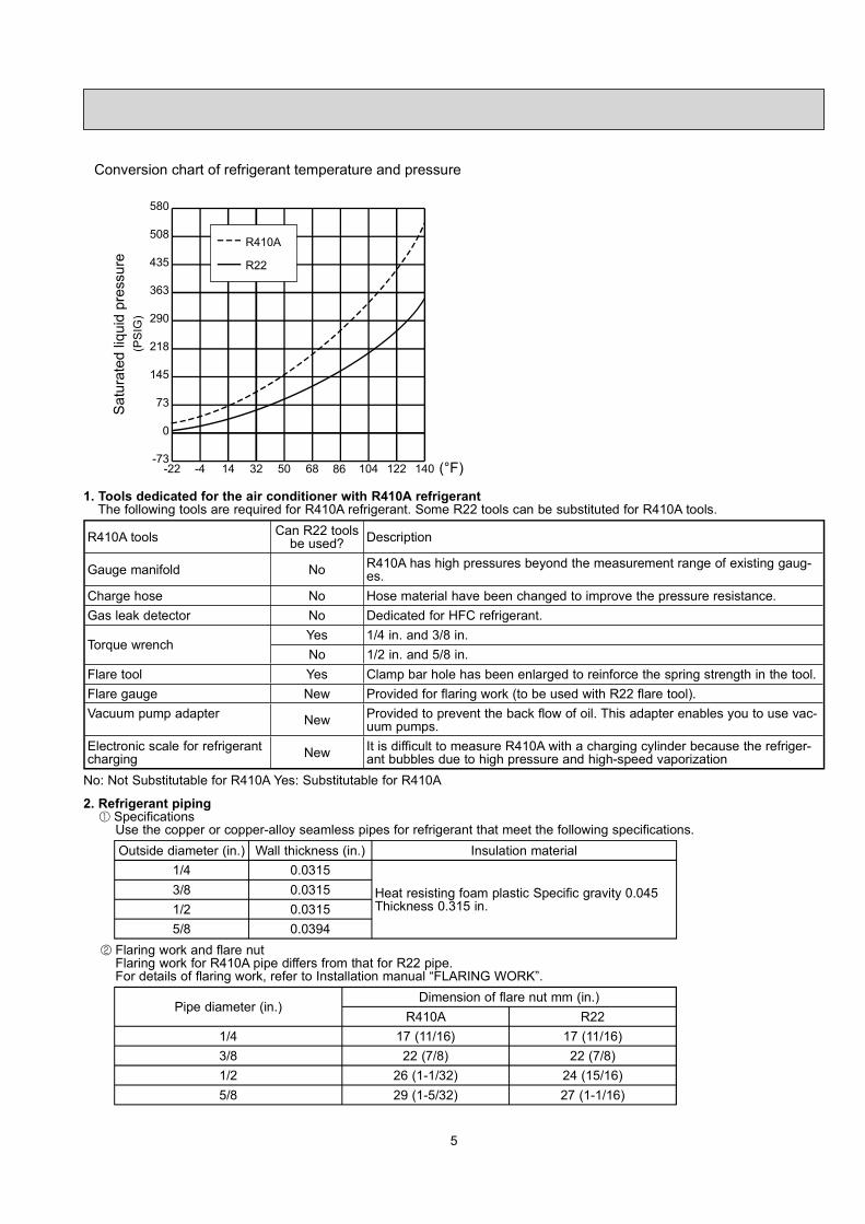
Conversion chart of refrigerant temperature and pressure

Sat

urat

edliq

uid

pres

sure

(°F)

1. Tools dedicated for the air conditioner with R410A refrigerantThe following tools are required for R410A refrigerant. Some R22 tools can be substituted for R410A tools.

R410A tools Can R22 toolsbe used? Description

Gauge manifold No R410A has high pressures beyond the measurement range of existing gaug-es.

Charge hose No Hose material have been changed to improve the pressure resistance.Gas leak detector No Dedicated for HFC refrigerant.

Torque wrenchYes 1/4 in. and 3/8 in.No 1/2 in. and 5/8 in.

Flare tool Yes Clamp bar hole has been enlarged to reinforce the spring strength in the tool.Flare gauge New Provided for flaring work (to be used with R22 flare tool).Vacuum pump adapter New Provided to prevent the back flow of oil. This adapter enables you to use vac-

uum pumps.Electronic scale for refrigerantcharging New It is difficult to measure R410A with a charging cylinder because the refriger-

ant bubbles due to high pressure and high-speed vaporization

No: Not Substitutable for R410A Yes: Substitutable for R410A

2. Refrigerant pipingSpecificationsUse the copper or copper-alloy seamless pipes for refrigerant that meet the following specifications.

Outside diameter (in.) Wall thickness (in.) Insulation material1/4 0.0315

Heat resisting foam plastic Specific gravity 0.045Thickness 0.315 in.

3/8 0.03151/2 0.03155/8 0.0394

Flaring work and flare nutFlaring work for R410A pipe differs from that for R22 pipe.

For details of flaring work, refer to Installation manual �FLARING WORK�.

Pipe diameter (in.)Dimension of flare nut mm (in.)

R410A R221/4 17 (11/16) 17 (11/16)3/8 22 (7/8) 22 (7/8)1/2 26 (1-1/32) 24 (15/16)5/8 29 (1-5/32) 27 (1-1/16)

6

3. Refrigerant oilApply the special refrigeration oil (accessories: packed with indoor unit) to the flare and the union seat surfaces.

4. Air purge� Do not discharge the refrigerant into the atmosphere.

Take care not to discharge refrigerant into the atmosphere during installation, reinstallation, or repairs to the refrigerant cir-cuit.

� Use the vacuum pump for air purging for the purpose of environmental protection.

5. Additional chargeFor additional charging, charge the refrigerant from liquid phase of the gas cylinder.If the refrigerant is charged from the gas phase, composition change may occur in the refrigerant inside the cylinder andthe outdoor unit. In this case, capacity of the refrigeration cycle decreases or normal operation can be impossible. However,charging the liquid refrigerant all at once may cause the compressor to be locked. Thus, charge the refrigerant slowly.

Electronic scale for refrigerant charging

Outdoor unit

Refrigerant gascylinderoperating valve

Refrigerant gas cylinderfor R410A with siphon

Refrigerant (liquid)

Service port

Gauge manifoldvalve (for R410A)

Union

Liquid pipe

Gas pipe

Stop valve

Indoor unit

Charge hose (for R410A)

PART NAMES AND FUNCTIONS2

Air outlet

Drain outlet

Piping

Drain hose

Air inlet(back and side)

MUZ-A09NA MUZ-A15NA MUY-A15NAMUZ-A12NA MUZ-A17NA MUY-A17NA

MUZ-A24NA MUY-A24NAMUZ-GA24NA MUY-GA24NA

Piping

Air outlet

Drain hose

Drain outlet

Air inlet(back and side)

7

Item Model MSZ-A09NA MSZ-A12NA

CapacityRated (Minimum-Maximum)

Cooling 1 Btu/h 9,000 (5,500-9,000) 12,000 (5,700-12,000)Heating 47 1 Btu/h 10,900 (5,200-12,600) 13,600 (5,200-13,600)

Capacity Heating 17 2 Btu/h 7,700 8,300Power consumptionRated (Minimum-Maximum)

Cooling 1 W 690 (390-690) 1,170 (395-1,170)Heating 47 1 W 860 (350-1,100) 1,160 (350-1,160)

Power consumption Heating 17 2 W 880 930EER 1 [SEER] 3 Cooling 13.0 [17.0] 10.3 [17.0]HSPF IV(V) 4 Heating 8.2 (7.1) 8.2 (7.1)COP Heating 1 3.71 3.44

Outdoor unit model MUZ-A09NAMUZ-A09NA - U1

MUZ-A09NA - 1MUZ-A09NA - U2

MUZ-A12NA

Power supply V , phase , Hz 208/230, 1, 60Max. fuse size (time delay) A 15Min. circuit ampacity A 12Fan motor F.L.A 0.52

Compressor

Model KNB092FPAHWinding resistance (at 68ûF) 0.49R.L.A 7.8L.R.A 9.2

Refrigerant control Liner expansion valveSound level 1 dB(A) 48Defrost method Reverse cycle

DimensionsW in. 31-1/2D in. 11-1/4H in. 21-5/8

Weight Ib. 82 75 82External Þnish Munsell 3Y 7.8/1.1Remote controller Wireless typeControl voltage (by built-in transformer) 12 - 24 VDCRefrigerant piping Not supplied

Refrigerant pipe size(Min. wall thickness)

Liquid in. 1/4 (0.0315)Gas in. 3/8 (0.0315)

Connection methodIndoor FlaredOutdoor Flared

Between the indoor &outdoor units

Height difference ft. 40Piping length ft. 65

Refrigerant charge (R410A) 2 lb. 5 oz. 2 lb. 2 lb. 5 oz.Refrigeration oil (Model) NEO22

NOTE: Test conditions are based on ARI 210/240.1: Rating conditions (Cooling) � Indoor: 80ûFDB, 67ûFWB, Outdoor: 95ûFDB, (75ûFWB) Rated frequency

(Heating) � Indoor: 70ûFDB, 60ûFWB, Outdoor: 47ûFDB, 43ûFWB Rated frequency2: (Heating) � Indoor: 70ûFDB, 60ûFWB, Outdoor: 17ûFDB, 15ûFWB Maximum frequency

3 SPECIFICATION

8

Item Model MSZ-A15NA MSY-A15NA MSZ-A17NA MSY-A17NA

CapacityRated(Minimum-Maximum)

Cooling 1 Btu/h 15,000(3,100-15,000)

15,000(3,100-15,000)

16,200(3,100-16,200)

16,200(3,100-16,200)

Heating 47 1 Btu/h 18,000(3,400-20,900) � 20,100

(3,400-20,900) �

Capacity Heating 17 2 Btu/h 13,000 � 13,000 � Power consumptionRated (Minimum-Maximum)

Cooling 1 W 1,690 (210-1,690) 1,690 (210-1,690) 2,070 (210-2,070) 2,070 (210-2,070)Heating 47 1 W 1,790 (250-2,330) � 2,150 (250-2,330) �

Power consumption Heating 17 2 W 1,740 � 1,740 � EER 1 [SEER] 3 Cooling 8.9 [16.0] 8.9 [16.0] 7.8 [16.0] 7.8 [16.0]HSPF IV(V) 4 Heating 8.2 (7.1) � 8.2 (7.1) � COP Heating 1 2.95 � 2.74 � Outdoor unit model MUZ-A15NA MUY-A15NA MUZ-A17NA MUY-A17NAPower supply V , phase , Hz 208/230, 1, 60Max. fuse size (time delay) A 15Min. circuit ampacity A 14Fan motor F.L.A 0.52

Compressor

Model SNB130FPDHWinding resistance (at 68 ûF) 0.45R.L.A 10.1L.R.A 12

Refrigerant control Liner expansion valveSound level 1 dB(A) 50 50 52 52Defrost method 51 � 53 �

DimensionsW in. 31-1/2D in. 11-1/4H in. 21-5/8

Weight Ib. 88External Þnish Munsell 3Y 7.8/1.1Remote controller Wireless typeControl voltage (by built-in transformer) 12 - 24 VDCRefrigerant piping Not supplied

Refrigerant pipe size(Min. wall thickness)

Liquid in. 1/4 (0.0315)Gas in. 1/2 (0.0315)

Connection methodIndoor FlaredOutdoor Flared

Between the indoor &outdoor units

Height difference ft. 40Piping length ft. 65

Refrigerant charge (R410A) 2 lb. 7 oz.Refrigeration oil (Model) NEO22

NOTE: Test conditions are based on ARI 210/240. 1: Rating conditions (Cooling) � Indoor: 80ûFDB, 67ûFWB, Outdoor: 95ûFDB, (75ûFWB) Rated frequency

(Heating) � Indoor: 70ûFDB, 60ûFWB, Outdoor: 47ûFDB, 43ûFWB Rated frequency2: (Heating) � Indoor: 70ûFDB, 60ûFWB, Outdoor: 17ûFDB, 15ûFWB Maximum frequency

9

Item Model MSZ-A24NA MSY-A24NA MSZ-GA24NA MSY-GA24NA

CapacityRated Minimum-Maximum)

Cooling 1 Btu/h 22,000(4,400-22,000)

22,000(4,400-22,000)

22,000(4,400-22,000)

22,000(4,400-22,000)

Heating 47 1 Btu/h 23,200(3,600-24,400) � 23,200

(3,600-24,400) �

Capacity Heating 17 2 Btu/h 15,200 � 15,200 �Power consumptionRated (Minimum-Maximum)

Cooling 1 W 2,880 (290-2,880) 2,880 (290-2,880) 2,500 (270-2,500) 2,500 (270-2,500)Heating 47 1 W 2,350 (260-2,570) � 2,140 (250-2,520) �

Power consumption Heating 17 2 W 1,960 � 1,870 �EER 1 [SEER] 3 Cooling 7.6 [16.0] 7.6 [16.0] 8.8 [17.5] 8.8 [17.5]HSPF IV(V) 4 Heating 8.2 (7.1) � 9.5 (7.1) �COP Heating 1 2.89 � 3.17 �Outdoor unit model MUZ-A24NA MUY-A24NA MUZ-GA24NA MUY-GA24NAPower supply V , phase , Hz 208/230, 1, 60Max. fuse size (time delay) A 20Min. circuit ampacity A 17Fan motor F.L.A 0.93

Compressor

Model SNB130FPDH SNB130FQBHWinding resistance (at 68 ûF) 0.45 0.98R.L.A 10.1 12.8L.R.A 16.0 16.0

Refrigerant control Liner expansion valveSound level 1 dB(A) 55Defrost method Reverse cycle

DimensionsW in. 33-1/16D in. 13H in. 33-7/16

Weight Ib. 128 117External Þnish Munsell 3Y 7.8 1.1Remote controller Wireless typeControl voltage (by built-in transformer) 12 - 24 VDCRefrigerant piping Not supplied

Refrigerant pipe size(Min. wall thickness)

Liquid in. 1/4 (0.0315)Gas in. 5/8 (0.0394)

Connection methodIndoor FlaredOutdoor Flared

Between the indoor &outdoor units

Height difference ft. 50Piping length ft. 100

Refrigerant charge (R410A) 4 lb.Refrigeration oil (Model) NEO22

NOTE: Test conditions are based on ARI 210/240. 1: Rating conditions (Cooling) � Indoor: 80ûFDB, 67ûFWB, Outdoor: 95ûFDB, (75ûFWB) Rated frequency

(Heating) � Indoor: 70ûFDB, 60ûFWB, Outdoor: 47ûFDB, 43ûFWB Rated frequency2: (Heating) � Indoor: 70ûFDB, 60ûFWB, Outdoor: 17ûFDB, 15ûFWB Maximum frequency

10

Test condition3, 4

Mode TestIndoor air condition (ûF) Outdoor air condition (ûF)Dry bulb Wet bulb Dry bulb Wet bulb

ARI

SEER(Cooling)

"A" Cooling Steady State at rated compres-sor Speed 80 67 95 (75)

"B-2" Cooling Steady State at rated com-pressor Speed 80 67 82 (65)

"B-1" Cooling Steady State at minimumcompressor Speed 80 67 82 (65)

Low ambient Cooling Steady State at mini-mum compressor Speed 80 67 67 (53.5)

Intermediate Cooling Steady State At Inter-mediate compressor Speed 5 80 67 87 (69)

HSPF(Heating)

Standard Rating-Heating at rated compres-sor Speed 70 60 47 43

Low temperature Heating at rated compres-sor Speed 70 60 17 15

Max temperature Heating at minimum com-pressor Speed 70 60 62 56.5

High temperature Heating at minimum com-pressor Speed 70 60 47 43

Frost Accumulation at rated compressorSpeed 70 60 35 33

Frost Accumulation at Intermediate com-pressor Speed 5 70 60 35 33

5: At Intermediate compressor Speed = ("Cooling rated compressor speed" - "minimum compressor speed") / 3 + "minimumcompressor speed".

OPERATING RANGE(1) POWER SUPPLY

Rated voltage Guaranteed Voltage (V)

Outdoor unit208/230 V1 phase60 Hz

Min.187 208 230 Max.253

(2) OPERATION

Mode ConditionIntake air temperature (°F)

Indoor OutdoorDB WB DB WB

Cooling

Standard temperature 80 67 95 �Maximum temperature 90 73 115 �Minimum temperature 67 57 14 �Maximum humidity 78% �

Heating

Standard temperature 70 60 47 43Maximum temperature 80 67 75 65

Minimum temperature 70 60 145 (MUZ-GA24)

134 (MUZ-GA24)

Except - U model

11

7-25/32

1-9/16

20-9/3211-25/32

2-19/32

19-11/16

3-3/164-25/32

33-1/16

Open as a rule20 inch or more ifthe front and bothsides are open

4 inch or more /8 inch or more ifthere are obstaclesto both sides

Open as a rule20 inch or more if the back,both sides and top are open

Air in

Air out

Service panel

Gas refrigerantpipe jointRefrigerant pipe(flared) ø5/8

Liquid refrigerantpipe jointRefrigerant pipe(flared) ø1/4

Drain hole ø1-5/8

4-3/8 13/16 Oval hole

REQUIRED SPACE

Air in

Liquid pipe :1/4 (flared)Gas pipe :3/8 (flared) ··· MUZ-A09/12NA

:1/2 (flared) ··· MUZ-A15/17NA, MUY-A15/17NA

6-23/32

2-23/32

15-3/4

1-9/16

7/8

31-1/2

19-11/165-15/16

11-29/32

17/3229/32 11-1/4

Air in

handle

Air in

Air out

2- 3/8 13/16 Oval hole

Drain hole ø1-5/8

{

REQUIRED SPACE Basically open 4 inch or morewithout any obstruction in frontand on both sides of the unit.

Open two sides of left,right, or rear side.

Unit: inchMUZ-A09NA MUZ-A12NA MUZ-A15NA MUZ-A17NA MUY-A15NA MUY-A17NA

MUZ-A24NA MUY-A24NA MUZ-GA24NA MUY-GA24NA

4 OUTLINES AND DIMENSIONS

23

MUZ-A09NA MUZ-A12NA MUZ-A15NA MUZ-A17NA MUZ-A24NA MUZ-GA24NAMUY-A15NA MUY-A17NA MUY-A24NA MUY-GA24NA

7-1. PERFORMANCE DATA1) COOLING CAPACITY

ModelIndoor air Outdoor intake air DB temperature (ûF)

IWB 75 85 95 105 115(ûF) TC SHC TPC TC SHC TPC TC SHC TPC TC SHC TPC TC SHC TPC

MUZ-A09NAMUZ-A09NA - U1

71 11.0 6.4 0.61 10.3 5.9 0.67 9.7 5.6 0.72 9.0 5.2 0.76 8.3 4.8 0.7967 10.4 7.4 0.58 9.7 6.9 0.64 9.0 6.4 0.69 8.4 5.9 0.73 7.7 5.5 0.7763 9.8 8.3 0.55 9.1 7.7 0.61 8.5 7.1 0.66 7.7 6.5 0.70 7.0 5.9 0.73

MUZ-A09NA - 1MUZ-A09NA - U2

71 11.0 6.4 0.61 10.3 5.9 0.67 9.7 5.6 0.72 9.0 5.2 0.76 8.3 4.8 0.7967 10.4 7.4 0.58 9.7 6.9 0.64 9.0 6.4 0.69 8.4 5.9 0.73 7.7 5.5 0.7763 9.8 8.3 0.55 9.1 7.7 0.61 8.5 7.1 0.66 7.7 6.5 0.70 7.0 5.9 0.73

MUZ-A12NA71 14.7 8.5 1.04 13.7 7.9 1.14 12.9 7.4 1.23 12.0 6.9 1.29 11.0 6.4 1.3567 13.9 9.9 0.98 13.0 9.2 1.08 12.0 8.5 1.17 11.2 7.9 1.24 10.3 7.3 1.3063 13.1 11.0 0.94 12.1 10.2 1.04 11.3 9.5 1.12 10.3 8.7 1.19 9.4 7.9 1.24

MUY-A15NAMUZ-A15NA

71 18.4 9.5 1.50 17.2 8.9 1.65 16.1 8.3 1.77 15.0 7.8 1.87 13.8 7.1 1.9467 17.4 11.3 1.42 16.2 10.5 1.56 15.0 9.8 1.69 14.0 9.1 1.79 12.8 8.3 1.8863 16.4 12.8 1.35 15.2 11.9 1.50 14.1 11.0 1.61 12.8 10.0 1.72 11.7 9.2 1.79

MUY-A17NAMUZ-A17NA

71 19.8 10.3 1.84 18.5 9.6 2.02 17.4 9.0 2.17 16.2 8.4 2.29 14.9 7.7 2.3867 18.8 12.2 1.74 17.5 11.4 1.91 16.2 10.5 2.07 15.1 9.8 2.19 13.9 9.0 2.3063 17.7 13.8 1.66 16.4 12.8 1.83 15.2 11.9 1.98 13.9 10.8 2.11 12.6 9.9 2.19

MUY-A24NAMUZ-A24NA

71 27.0 13.4 2.56 25.2 12.5 2.81 23.7 11.7 3.02 22.0 10.9 3.18 20.2 10.1 3.3167 25.5 16.1 2.42 23.8 15.0 2.66 22.0 13.9 2.88 20.5 12.9 3.05 18.8 11.9 3.2063 24.0 18.3 2.30 22.2 17.0 2.55 20.7 15.8 2.75 18.8 14.4 2.94 17.2 13.1 3.05

MUY-GA24NAMUZ-GA24NA

71 27.0 13.4 2.23 25.2 12.5 2.44 23.7 11.7 2.63 22.0 10.9 2.76 20.2 10.1 2.8867 25.5 16.1 2.10 23.8 15.0 2.31 22.0 13.9 2.50 20.5 12.9 2.65 18.8 11.9 2.7863 24.0 18.3 2.00 22.2 17.0 2.21 20.7 15.8 2.39 18.8 14.4 2.55 17.2 13.1 2.65

NOTE: 1. IWB: Intake air wet-bulb temperatureTC: Total Capacity (×103 Btu/h)SHC: Sensible Heat Capacity (×103 Btu/h)TPC: Total Power Consumption (kW)

2. SHC is based on 80ûF of indoor Intake air DB temperature.

2) COOLING CAPACITY CORRECTIONS

ModelRefrigerant piping length (one way: ft.)

25 (std.) 40 65 100MSZ-A09/12/15/17NAMSY-A15/17NA 1.0 0.954 0.878

MSZ-A24NAMSY-A24NAMSZ-GA24NAMSY-GA24NA

1.0 0.95 0.878 0.713

7 DATA

24

3) HEATING CAPACITY

ModelIndoor air Outdoor intake air WB temperature (ûF)

IDB 5 15 25 35 43 45 55(ûF) TC TPC TC TPC TC TPC TC TPC TC TPC TC TPC TC TPC

MUZ-A09NAMUZ-A09NA - U1

75� �

6.3 0.64 7.9 0.75 9.4 0.84 10.6 0.88 11.0 0.89 12.4 0.9370 6.7 0.62 8.2 0.74 9.6 0.82 10.9 0.86 11.2 0.88 12.7 0.9165 6.9 0.59 8.6 0.71 10.0 0.80 11.2 0.84 11.6 0.85 13.0 0.89

MUZ-A09NA - 1MUZ-A09NA - U2

75� �

6.3 0.64 7.9 0.75 9.4 0.84 10.6 0.88 11.0 0.89 12.4 0.9370 6.7 0.62 8.2 0.74 9.6 0.82 10.9 0.86 11.2 0.88 12.7 0.9165 6.9 0.59 8.6 0.71 10.0 0.80 11.2 0.84 11.6 0.85 13.0 0.89

MUZ-A12NA75

� �7.9 0.86 9.9 1.02 11.8 1.13 13.3 1.19 13.7 1.21 15.5 1.25

70 8.4 0.84 10.2 0.99 12.0 1.10 13.6 1.16 14.0 1.18 15.8 1.2365 8.6 0.80 10.7 0.96 12.4 1.07 14.0 1.13 14.4 1.15 16.2 1.21

MUZ-A15NA75

� �10.4 1.33 13.1 1.57 15.6 1.75 17.6 1.83 18.1 1.86 20.5 1.93

70 11.1 1.29 13.5 1.53 15.9 1.70 18.0 1.79 18.5 1.83 21.0 1.9065 11.3 1.24 14.1 1.48 16.5 1.66 18.5 1.75 19.1 1.77 21.4 1.86

MUZ-A17NA75

� �11.7 1.60 14.6 1.88 17.4 2.10 19.6 2.20 20.2 2.24 22.9 2.32

70 12.4 1.55 15.1 1.84 17.8 2.04 20.1 2.15 20.7 2.19 23.4 2.2865 12.7 1.48 15.8 1.77 18.4 1.99 20.7 2.10 21.3 2.13 23.9 2.24

MUZ-A24NA75

� �13.5 1.75 16.8 2.06 20.1 2.29 22.6 2.41 23.3 2.44 26.4 2.54

70 14.3 1.69 17.4 2.01 20.5 2.23 23.2 2.35 23.9 2.40 27.0 2.4965 14.6 1.62 18.2 1.94 21.2 2.17 23.9 2.29 24.6 2.33 27.6 2.44

MUZ-GA24NA75 10.2 1.26 13.5 1.59 16.8 1.87 20.1 2.09 22.6 2.19 23.3 2.23 26.4 2.3170 11.0 1.21 14.3 1.54 17.4 1.83 20.5 2.03 23.2 2.14 23.9 2.18 27.0 2.2765 11.6 1.16 14.6 1.48 18.2 1.77 21.2 1.98 23.9 2.09 24.6 2.12 27.6 2.23

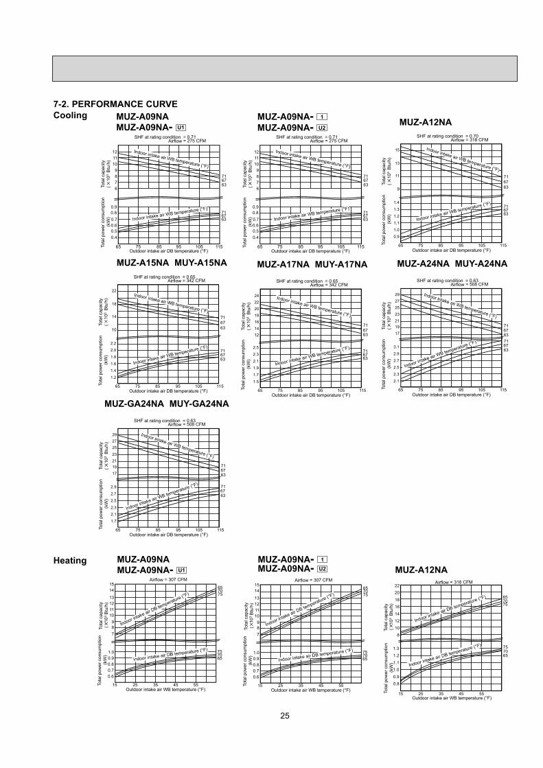
NOTE: 1. IDB: Intake air dry-bulb temperatureTC: Total Capacity (×103 Btu/h)TPC: Total Power Consumption (kW)

2. Above data is for heating operation without any frost.

How to operate with fixed operational frequency of the compressor.1. Press the EMERGENCY OPERATION switch on the front of the indoor unit, and select either EMERGENCY COOL

mode or EMERGENCY HEAT mode before starting to operate the air conditioner.2. The compressor starts with operational frequency.3. The fan speed of the indoor unit is High.4. This operation continues for 30 minutes.5. In order to release this operation, press the EMERGENCY OPERATION switch twice or once, or press any button on

the remote controller.

25

7-2. PERFORMANCE CURVE

657075

757065

Tota

lpow

erco

nsum

ptio

n(k

W)

Tota

lcap

acity

(10

3B

tu/h

)

Outdoor intake air WB temperature (°F)

= 307 CFMAirflow

12

14

10

89

11

13

15

7

1.0

15 25 35 45 55

0.8

0.60.7

0.9

657075

757065

20

12

8

16

22

18

10

14

= 318 CFMAirflow

15 25 35 45 55Outdoor intake air WB temperature (°F)

1.3

0.8

0.9

1.0

1.1

1.2

Tota

lpow

erco

nsum

ptio

n(k

W)

Tota

lcap

acity

(10

3B

tu/h

)

Cooling

716763

716763

Outdoor intake air DB temperature (°F)

SHF at rating condition = 0.71= 275 CFMAirflow

6

87

9101112

0.9

65 75 85 95 105 115

0.70.6

0.8

0.50.4

Tota

lpow

erco

nsum

ptio

n(k

W)

Tota

lcap

acity

(10

3B

tu/h

)

716763

716763

24

22

20

18

12

16

14

2.5

2.3

2.1

1.9

1.7

1.5

SHF at rating condition = 0.65= 342 CFMAirflow

65 75 85 95 105 115Outdoor intake air DB temperature (°F)

Tota

lpow

erco

nsum

ptio

n(k

W)

Tota

lcap

acity

(10

3B

tu/h

)

71

6367

71

6367

27

29

23

19

25

21

17

3.1

2.9

2.7

2.5

2.3

2.1

SHF at rating condition = 0.63= 508 CFMAirflow

65 75 85 95 105 115Outdoor intake air DB temperature (°F)

Tota

lpow

erco

nsum

ptio

n(k

W)

Tota

lcap

acity

(10

3B

tu/h

)

716763

716763

15

13

9

11

1.4

1.3

1.2

1.1

1.0

0.9

SHF at rating condition = 0.70= 318 CFMAirflow

65 75 85 95 105 115Outdoor intake air DB temperature (°F)

Tota

lpow

erco

nsum

ptio

n(k

W)

Tota

lcap

acity

(10

3B

tu/h

)

716763

716763

22

18

10

14

2.2

2.0

1.8

1.6

1.4

1.2

SHF at rating condition = 0.65= 342 CFMAirflow

65 75 85 95 105 115Outdoor intake air DB temperature (°F)

Tota

lpow

erco

nsum

ptio

n(k

W)

Tota

lcap

acity

(10

3B

tu/h

)

MUZ-A09NAMUZ-A09NA- U1

MUZ-A09NAMUZ-A09NA- U1

MUZ-A12NA

MUZ-A15NA MUY-A15NA MUZ-A17NA MUY-A17NA MUZ-A24NA MUY-A24NA

HeatingMUZ-A12NA

MUZ-A09NA- 1

MUZ-A09NA- U2

MUZ-A09NA- 1

MUZ-A09NA- U2

716763

716763

Outdoor intake air DB temperature (°F)

SHF at rating condition = 0.71= 275 CFMAirflow

6

87

9101112

0.9

65 75 85 95 105 115

0.70.6

0.8

0.50.4

Tota

lpow

erco

nsum

ptio

n(k

W)

Tota

lcap

acity

(10

3B

tu/h

)

657075

757065

Tota

lpow

erco

nsum

ptio

n(k

W)

Tota

lcap

acity

(10

3B

tu/h

)

Outdoor intake air WB temperature (°F)

= 307 CFMAirflow

12

14

10

89

11

13

15

7

1.0

15 25 35 45 55

0.8

0.60.7

0.9

71

6367

71

6367

27

29

23

19

25

21

17

2.9

2.7

2.5

2.3

2.1

1.7

SHF at rating condition = 0.63= 508 CFMAirflow

65 75 85 95 105 115Outdoor intake air DB temperature (°F)

Tota

lpow

erco

nsum

ptio

n(k

W)

Tota

lcap

acity

(10

3B

tu/h

)

MUZ-GA24NA MUY-GA24NA

26

657075

757065

Outdoor intake air WB temperature (°F)

Airflow= 381 CFM

18

22

24

14

10

1.81.9

1.7

15 25 35 45 55

1.5

1.31.4

1.6

Tota

lpow

erco

nsum

ptio

n(k

W)

Tota

lcap

acity

(×10

3B

tu/h

)

657075

757065

24

20

12

16

= 381 CFMAirflow

15 25 35 45 55Outdoor intake air WB temperature (°F)

2.4

1.4

1.6

1.8

2.0

2.2

Tota

lpow

erco

nsum

ptio

n(k

W)

Tota

lcap

acity

(10

3B

tu/h

)

657075

757065

28

26

24

22

16

14

20

18

2.6

1.6

= 568 CFMAirflow

15 25 35 45 55Outdoor intake air WB temperature (°F)

1.8

2.0

2.2

2.4

Tota

lpow

erco

nsum

ptio

n(k

W)

Tota

lcap

acity

(10

3B

tu/h

)

MUZ-A15NA MUZ-A17NA MUZ-A24NA

10

1214

16

1820

2224

26

2830

32 657075

757065

= 568 CFMAirflow

155 25 35 45 55Outdoor intake air WB temperature (°F)

Tota

lpow

erco

nsum

ptio

n(k

W)

Tota

lcap

acity

(10

3B

tu/h

)

1.0

1.2

1.4

1.6

1.8

2.0

2.2

2.4

MUZ-GA24NA

This value of frequency is not the same as the actual frequency in operating. Refer to 7-5 and 7-6 for the relationshipsbetween frequency and capacity.

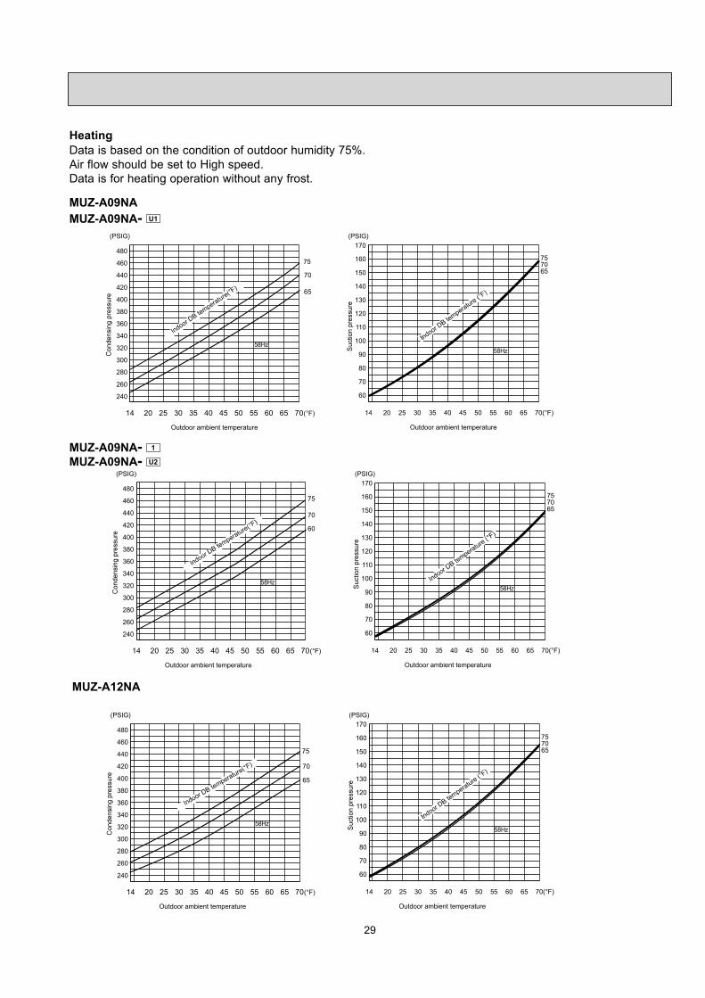
Data is based on the condition of indoor humidity 50%.Air flow should be set to High speed.

7-3. Condensing pressure

Cooling

68 70 75 80 85 90 95 100 105(°F)110115120125130135140145150155160165170

(PSIG)86807570

Outdoor ambient temperature

(PSIG)

86

80

75

70

68 70 75 80 85 90 95 100 105(°F)260

280

300

320

340

360

380

400

420

Outdoor ambient temperature

MUZ-A09NAMUZ-A09NA- U1

27

68 70 75 80 85 90 95 100 105(°F)9095

100105110115120125130135140145150

(PSIG)

86807570

Outdoor ambient temperature

(PSIG)

86

80

75

70

68 70 75 80 85 90 95 100 105(°F)180

220

260

300

340

380

420

460

500

Outdoor ambient temperature

MUZ-A12NA

MUZ-A09NA- 1

MUZ-A09NA- U2

(PSIG)

86807570

68 70 75 80 85 90 95 100 105(°F)280

300

340

360

380

400

420

460

480

Outdoor ambient temperature

320

68 70 75 80 85 90 95 100 105(°F)110115120125130135140145150155160165170

Outdoor ambient temperature

(PSIG)

86

80

75

70

440

MUZ-A15NAMUY-A15NA

68 70 75 80 85 90 95 100 105(°F)80859095

100105110115120125130135140

(PSIG)

86807570

Outdoor ambient temperature

(PSIG)

86

80

75

70

68 70 75 80 85 90 95 100 105(°F)260

300

340

380

420

460

500

540

580

Outdoor ambient temperature

28

MUZ-A24NAMUY-A24NA

68 70 75 80 85 90 95 100 105(°F)707580859095

100105110115120125130

(PSIG)

86807570

Outdoor ambient temperature

(PSIG)

86

80

75

70

68 70 75 80 85 90 95 100 105(°F)260

300

340

380

420

460

500

540

580

Outdoor ambient temperature

MUZ-A17NAMUY-A17NA

(PSIG)

86807570

68 70 75 80 85 90 95 100 105(°F)80859095

100105110115120125130135140

Outdoor ambient temperature

(PSIG)

86

80

7570

68 70 75 80 85 90 95 100 105(°F)260

300

340

380

420

460

500

540

580

Outdoor ambient temperature

MUZ-GA24NAMUY-GA24NA

(PSIG)

86807570 86

80

75

70

68 70 75 80 85 90 95 100 105(°F)260

300

340

380

420

460

500

540

580

Outdoor ambient temperature

68 70 75 80 85 90 95 100 105(°F)Outdoor ambient temperature

(PSIG)

100

110

120

130

140

150

29

Data is based on the condition of outdoor humidity 75%.Air flow should be set to High speed.Data is for heating operation without any frost.

Heating

MUZ-A12NA

75

70

65

(PSIG) (PSIG)

Outdoor ambient temperature

14 20 25 30 35 40 45 50 55 60 65 70(°F)

340

320

300

280

260

240

360

380

400

440

420

460

480757065

Outdoor ambient temperature

14 20 25 30 35 40 45 50 55

58Hz58Hz

60 65 70(°F)

70

60

80

90

100

110

120

130

140

150

160

170

MUZ-A09NAMUZ-A09NA- U1

MUZ-A09NA- 1

MUZ-A09NA- U2

75

70

60

(PSIG) (PSIG)

Outdoor ambient temperature

14 20 25 30 35 40 45 50 55 60 65 70(°F)

340

320

300

280

260

240

360

380

400

440

420

460

480757065

Outdoor ambient temperature

14 20 25 30 35 40 45 50 55

58Hz58Hz

60 65 70(°F)

70

60

80

90

100

110

120

130

140

150

160

170

30

MUZ-A24NA

MUZ-A17NA

75

7065

(PSIG) (PSIG)

Outdoor ambient temperature

14 20 25 30 35 40 45 50 55 60 65 70(°F)

260

220

180

140

100

300

340

380

460

420

500

540

580

620

757065

Outdoor ambient temperature

14 20 25 30 35 40 45 50 55

58Hz58Hz

60 65 70(°F)

70

60

50

80

90

100

110

120

130

140

150

160

75

70

65

(PSIG) (PSIG)

Outdoor ambient temperature

14 20 25 30 35 40 45 50 55 60 65 70(°F)

280

260

240

220

200

300

320

340

380

360

400

420

440

460

757065

Outdoor ambient temperature

14 20 25 30 35 40 45 50 55

58Hz

60 65 70(°F)

70

60

50

80

90

100

110

120

130

140

150

160

58Hz

MUZ-A15NA

757065

(PSIG) (PSIG)

Outdoor ambient temperature

14 20 25 30 35 40 45 50 55 60 65 70(°F)

260

220

180

140

100

300

340

380

460

420

500

540

580

620

757065

Outdoor ambient temperature

14 20 25 30 35 40 45 50 55

58Hz58Hz

60 65 70(°F)

70

60

50

80

90

100

110

120

130

140

150

160

31

MUZ-GA24NA

(PSIG)

200

220

240

260

280

300

320

340

360

380 75

70

65

(PSIG)

Outdoor ambient temperature

155 2010 25 30 35 40 45 50 55 60 65 70(°F)

58Hz

405060708090

100110120130140150160170 75

7065

58Hz

Outdoor ambient temperature

15 20105 25 30 35 40 45 50 55 60 65 70(°F)

32

7-4. STANDARD OPERATION DATAModel MUZ-A09NA MSZ-A12NA

Item Unit Cooling Heating Cooling Heating Cooling Heating

Capacity Btu/h 9,000 10,900 9,000 10,900 12,000 13,600

SHF � 0.71 � 0.71 � 0.70 �

Input kW 0.690 0.860 0.690 0.860 1,170 1,160

Rated frequency Hz 50 61 50 63 76 76

Indoor unit MSZ-A09NA MSZ-A12NA

Power supply (V, Phase, Hz) 208 / 230, 1, 60 208 / 230, 1, 60

Input kW 0.016 0.021

Fan motor current A 0.18 / 0.16 0.23 / 0.21

Outdoor unit MUZ-A09NAMUZ-A09NA- U1

MUZ-A09NA- 1

MUZ-A09NA- U2 MUZ-A12NA

Power supply (V, phase, Hz) 208 / 230, 1, 60 208 / 230, 1, 60

Input kW 0.674 0.844 0.674 0.844 1.149 1.139

Comp. current A 2.80 / 2.53 3.63 / 3.28 3.14 / 2.84 3.89 / 3.52 5.08 / 4.59 5.03 / 4.54

Fan motor current A 0.37 / 0.34 0.33 / 0.30 0.37 / 0.34

Condensing pressure PSIG 363 368 393 372 395 393

Suction pressure PSIG 144 109 144 102 124 103

Discharge temperature °F 145 153 155 165 169 164

Condensing temperature °F 107 108 113 109 112 113

Suction temperature °F 55 37 56 38 54 35

Comp. shell bottom temp °F 140 147 149 159 163 158

Ref. pipe length ft. 25 25

Refrigerant charge (R410A) � 2 lb. 5 oz. 2 lb. 2 lb. 5 oz.

Intake air temperatureDB °F 80 70 80 70 80 70

WB °F 67 60 67 60 67 60

Discharge air temperatureDB °F 57 105 57 105 56 108

WB °F 56 71 56 71 54 72

Fan speed (High) rpm 1,080 1,080 1,080 1,080 1,220 1,220

Airßow (High) CFM 275 (Wet) 307 275 (Wet) 307 318 (Wet) 353

Intake air temperatureDB °F 95 47 95 47 95 47

WB °F � 43 � 43 � 43

Fan speed rpm 840 840 840 840 840 840

Airßow CFM 1,094 1,094 1,129 1,129 1,094 1,094

33

Model MSZ-A15NAMSY-A15NA MSZ-A15NA MSZ-A17NA

MSY-A17NA MSZ-A17NA

Item Unit Cooling Heating Cooling Heating

Capacity Btu/h 15,000 18,000 16,200 20,100

SHF - 0.65 � 0.65 �

Input kW 1.69 1.79 2.07 2.15

Rated frequency Hz 77 78 89 88

Indoor unit MSZ-A15NA, MSY-A15NA MSZ-A17NA, MSY-A17NA

Power supply (V, Phase, Hz) 208 / 230, 1, 60 208 / 230, 1, 60

Input kW 0.030 0.030

Fan motor current A 0.31 / 0.28 0.31 / 0.28

Outdoor unit MUZ-A15NAMUY-A15NA MUZ-A15NA MUZ-A17NA

MUY-A17NA MUZ-A17NA

Power supply (V, phase, Hz) 208 / 230, 1, 60 208 / 230, 1, 60

Input kW 1.660 1.760 2.040 2.120

Comp. current A 7.56 / 6.84 8.14 / 7.36 9.43 / 8.52 9.93 / 8.98

Fan motor current A 0.42 / 0.38 0.42 / 0.38

Condensing pressure PSIG 425 458 442 493

Suction pressure PSIG 115 95 106 92

Discharge temperature °F 182 180 189 194

Condensing temperature °F 117 125 120 130

Suction temperature °F 47 30 40 28

Comp. shell bottom temp °F 161 153 167 167

Ref. pipe length ft. 25 25

Refrigerant charge (R410A) - 2 lb. 7 oz. 2 lb. 7 oz.

Intake air temperatureDB °F 80 70 80 70

WB °F 67 60 67 60

Discharge air temperatureDB °F 53 116 52 120

WB °F 52 74 51 75

Fan speed (High) rpm 1,300 1,300 1,300 1,300

Airßow (High) CFM 342 (Wet) 381 342 (Wet) 381

Intake air temperatureDB °F 95 47 95 47

WB °F � 43 � 43

Fan speed rpm 950 950 950 950

Airßow CFM 1,249 1,249 1,249 1,249

34

Model MSZ-A24NAMSY-A24NA MSZ-A24NA MSZ-GA24NA

MSY-GA24NA MSZ-GA24NA

Item Unit Cooling Heating Cooling Heating

Capacity Btu/h 22,000 23,200 22,000 23,200

SHF - 0.63 � 0.63 �

Input kW 2.88 2.35 2.50 2.14

Rated frequency Hz 110 101 101 96

Indoor unit MSZ-A24NA, MSY-A24NA MSZ-GA24NA, MSY-GA24NA

Power supply (V, Phase, Hz) 208 / 230, 1, 60

Input kW 0.053

Fan motor current A 0.52 / 0.47

Outdoor unit MUZ-A24NAMUY-A24NA MUZ-A24NA MUZ-GA24NA

MUY-GA24NA MUZ-GA24NA

Power supply (V, phase, Hz) 208 / 230, 1, 60

Input kW 2.827 2.297 2.447 2.087

Comp. current A 12.81 / 11.59 11.10 / 10.04 10.82 / 9.78 9.32 / 8.43

Fan motor current A 0.80 / 0.72 0.80 / 0.72 0.64 / 0.59

Condensing pressure PSIG 447 401 413 375

Suction pressure PSIG 107 92 130 103

Discharge temperature °F 181 170 168 173

Condensing temperature °F 121 115 119 112

Suction temperature °F 37 29 43 31

Comp. shell bottom temp °F 161 148 160 164

Ref. pipe length ft. 25

Refrigerant charge (R410A) - 4 lb.

Intake air temperatureDB °F 80 70 80 70

WB °F 67 60 67 60

Discharge air temperatureDB °F 56 108 56 108

WB °F 55 72 55 72

Fan speed (High) rpm 1,310

Airßow (High) CFM 385 (Wet) 341 385 (Wet) 341

Intake air temperatureDB °F 95 47 95 47

WB °F � 43 � 43

Fan speed rpm 800 740

Airßow CFM 1,729 1,660

35

7-5. CAPACITY AND INPUT CORRECTION BY INVERTER OUTPUT FREQUENCY

Correction of Cooling total input

Inpu

tcor

rect

ion

fact

ors

The operational frequency of compressor

Correction of Cooling capacity

Cap

acity

corr

ectio

nfa

ctor

s

The operational frequency of compressor

Correction of Cooling capacity

Cap

acity

corr

ectio

nfa

ctor

s

The operational frequency of compressor

Correction of Cooling total input

The operational frequency of compressor

Correction of Heating total input

The operational frequency of compressor

Correction of Heating capacity

The operational frequency of compressor

Correction of Heating total input

Inpu

tcor

rect

ion

fact

ors

The operational frequency of compressor

Correction of Heating capacity

Cap

acity

corr

ectio

nfa

ctor

s

The operational frequency of compressor

Inpu

tcor

rect

ion

fact

ors

MUZ-A09NAMUZ-A09NA - U1

MUZ-A12NA

0 50 100 150(Hz)0.0

0.5

1.0

1.5

0 50 100 150(Hz)0.0

0.5

1.0

1.5

0 50 100 150(Hz)0.0

0.5

1.0

1.5

2.0

0 50 100 150(Hz)0.0

0.5

1.0

1.5

2.0

0 50 100 150(Hz)0.0

0.5

1.0

1.5

0 50 100 150(Hz)0.0

0.5

1.0

1.5

0 50 100 150(Hz)0.0

0.5

1.0

1.5

2.0

0 50 100 150(Hz)0.0

0.5

1.0

1.5

2.0

Cap

acity

corr

ectio

nfa

ctor

s

Inpu

tcor

rect

ion

fact

ors

Cap

acity

corr

ectio

nfa

ctor

s

Correction of Cooling capacity

The operational frequency of compressor

Correction of Cooling total input

The operational frequency of compressor

Correction of Heating total input

The operational frequency of compressor

Correction of Heating capacity

The operational frequency of compressor

MUY-A15NAMUZ-A15NA

MUZ-A15NA

0 50 100 1500.0

0.5

1.0

1.5

(Hz) 0 50 100 1500.0

0.5

1.0

1.5

(Hz) 0 50 100 1500.0

0.5

1.0

1.5

(Hz) (Hz)0 50 100 1500.0

0.5

1.0

1.5

MUZ-A09NA - 1

MUZ-A09NA - U2

Correction of Cooling total input

Inpu

tcor

rect

ion

fact

ors

The operational frequency of compressor

Correction of Cooling capacity

Cap

acity

corr

ectio

nfa

ctor

s

The operational frequency of compressor

Correction of Heating total input

The operational frequency of compressor

Correction of Heating capacity

The operational frequency of compressorIn

putc

orre

ctio

nfa

ctor

s0 50 100 150(Hz)

0.0

0.5

1.0

1.5

0 50 100 150(Hz)0.0

0.5

1.0

1.5

0 50 100 150(Hz)0.0

0.5

1.0

1.5

2.0

0 50 100 150(Hz)0.0

0.5

1.0

1.5

2.0

36

MUY-A24NAMUZ-A24NA

MUZ-A24NA

Cap

acity

corr

ectio

nfa

ctor

s

Inpu

tcor

rect

ion

fact

ors

Inpu

tcor

rect

ion

fact

ors

Cap

acity

corr

ectio

nfa

ctor

sCorrection of Cooling capacity

The operational frequency of compressor

Correction of Cooling total input

The operational frequency of compressor

Correction of Heating total input

The operational frequency of compressor

Correction of Heating capacity

Correction of Heating capacity

The operational frequency of compressor0 50 100 150

0.0

0.5

1.0

1.5

(Hz) 0 50 100 1500.0

0.5

1.0

1.5

(Hz) 0 50 100 1500.0

0.5

1.0

1.5

(Hz) 0 50 100 1500.0

0.5

1.0

1.5

(Hz)

MUY-GA24NAMUZ-GA24NA

MUZ-GA24NA

Cap

acity

corr

ectio

nfa

ctor

s

Inpu

tcor

rect

ion

fact

ors

Inpu

tcor

rect

ion

fact

ors

Cap

acity

corr

ectio

nfa

ctor

s

Correction of Cooling capacity

The operational frequency of compressor

Correction of Cooling total input

The operational frequency of compressor

Correction of Heating total input

The operational frequency of compressorThe operational frequency of compressor0 50 100 150

0.0

0.5

1.0

1.5

(Hz) 0 50 100 1500.0

0.5

1.0

1.5

(Hz) 0 50 100 1500.0

0.5

1.0

1.5

(Hz) 0 50 100 1500.0

0.5

1.0

1.5

(Hz)

Cap

acity

corr

ectio

nfa

ctor

s

Inpu

tcor

rect

ion

fact

ors

Inpu

tcor

rect

ion

fact

ors

Cap

acity

corr

ectio

nfa

ctor

s

Correction of Cooling capacity

The operational frequency of compressor

Correction of Cooling total input

The operational frequency of compressor

Correction of Heating total input

The operational frequency of compressor

Correction of Heating capacity

The operational frequency of compressor

MUY-A17NAMUZ-A17NA

MUZ-A17NA

0 50 100 1500.0

0.5

1.0

1.5

(Hz) 0 50 100 1500.0

0.5

1.0

1.5

(Hz) 0 50 100 1500.0

0.5

1.0

1.5

(Hz) 0 50 100 1500.0

0.5

1.0

1.5

(Hz)

7-6. TEST RUN OPERATION (How to operate fixed-frequency operation)1. Press EMERGENCY OPERATION switch to COOL or HEAT mode (COOL: Press once, HEAT: Press twice).2. Test run operation starts and continues to operate for 30 minutes.3. Compressor operates at rated frequency in COOL mode or 58 Hz in HEAT mode.4. Indoor fan operates at High speed.5. After 30 minutes, test run operation finishes and EMERGENCY OPERATION starts (operation frequency of compressor

varies).6. To cancel test run operation (EMERGENCY OPERATION), press EMERGENCY OPERATION switch or any button on

remote controller.


Recommended