+ All Categories
Home > Documents > 1 TeV pair backgrounds with ILD_O1_v02

1 TeV pair backgrounds with ILD_O1_v02

Date post: 31-Dec-2015
Category:
Upload: daria-riley
View: 26 times
Download: 2 times
Share this document with a friend
Description:
1 TeV pair backgrounds with ILD_O1_v02. Preliminary study of pair background hits with a new ILD detector model Hits in VXD, TPC, FTD, BCAL. Akiya Miyamoto KEK 25-April-2012 KILC12 Software Session. TDR beam parameter. - PowerPoint PPT Presentation
Popular Tags:
14
1 TeV pair backgrounds with ILD_O1_v02 Akiya Miyamoto KEK 25-April-2012 KILC12 Software Session Preliminary study of pair background hits with a new ILD detector model Hits in VXD, TPC, FTD, BCAL
Transcript

1 TeV pair backgroundswith ILD_O1_v02

Akiya MiyamotoKEK

25-April-2012KILC12 Software Session

Preliminary study of pair background hits with a new ILD detector model

Hits in VXD, TPC, FTD, BCAL

            L upgrade   Ecm upgrade  Center of mass energy GeV 250 350 500  500  1000 1000                A1 B1b  Collision rate Hz 5 5 5  5  4 4 Number of bunches   1312 1312 1312  1312  2450 2450 e-(e+) bunch poplation x1010 2 2 2  2  1.74 1.74 Bunch separation ns 554 554 554  366  366 366                     RMS bunch length mm 0.3 0.3 0.3  0.3  0.25 0.225 Electron RMS energy spread % 0.190 0.158 0.125   0.125   0.083 0.085  Positron RMS energy spread % 0.150 0.100 0.070   0.070   0.043 0.047  Electron polarization % 80 80 80  80  80 80 Positron polarization % 30 30 30  30  20 20                     Horizontal emittance m 10 10 10  10  10 10 Vertical emittance nm 35 35 35  35  30 30                     IP horizontal beta function mm 12 15 11  11  22.6 11 IP vertial beta function(no TF) mm 0.48 0.48 0.48  0.48  0.25 0.23 IP RMS horizontal beam size nm 700 662 474  474  481 335 

IP RMS vertical beam size(no TF) mm 8.3 7 5.9  5.9  2.8 2.7                     Coherent waist shift m 250 250 250  250  190 190 

Luminosity incl. waist shift x1034cm-2s-1 0.8 0.9 1.8  3.6  3.6 4.9 Fraction of lum. in top 1% % 84.1 79.3 62.5  62.3  60.2 45.5 

Average energy loss % 1.23 1.75 4.3  4.3  5.3 9.9 

Number of pairs per BX x103 70.5 89.1 139  139  200.5 382.6>1MeV

TDR beam parameterhttp://ilc-edmsdirect.desy.de/ilc-edmsdirect/item.jsp?edmsid=D00000000965015

325 April 2012 Akiya Miyamoto

KILC12 Software Session

1 TeV B1b_ws

By Mikael Berggren

4KILC12 Software Session

Simulation conditions GuineaPig files : produced by Hartin. Taken from

/afs/desy.de/group/flc/pool/analysis/public/pairs/hartin/[1000,500]GeV

- Waisty_opt_Jan2012_1000GeV_B1b_runX_waisty_190 20BX- Waisty_opt_Jan2012_500GeV_run9_waisty_250 7BX

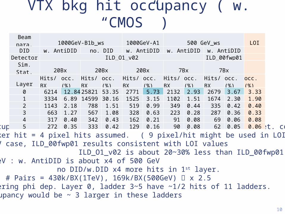
Mokka: ilcsoft-v01-13-04, Mokka-07-07 ILD_O1_v02 ( exist overlap geometry in beam pipe, … not perfect yet. ) ILD_00fwp01 (500GeV) for comparison with LOI Setting for Anti-DID and pair simulation in mokka.steer

/Mokka/init/EditGeometry/rmSubDetector SField01 /Mokka/init/EditGeometry/addSubDetector fieldX03 1000 /Mokka/init/lcioDetailedTRKHitMode SITCollection /Mokka/init/lcioDetailedTRKHitMode VXDCollection /Mokka/init/lcioDetailedTRKHitMode FTDCollection /Mokka/init/lcioDetailedTRKHitMode TPCCollection /Mokka/init/lcioDetailedTRKHitMode TPCSpacePointCollection /Mokka/init/TPCLowPtStepLimit true /Mokka/init/pairParticlesPerEvent 100 /Mokka/init/TPCCut 0 keV /Mokka/init/RangeCut 0.1mm25 April 2012 Akiya Miyamoto

Overlap checkby Ch.Grefe

5KILC12 Software Session

Z distribution

25 April 2012 Akiya Miyamoto

6

Phi dependance of VTX hits

34

59

Layer 2 ladder 9: Z distribution of ladder 9 is similar to layer0 ladders. Many hits due to back scattering ?

VTX geometry to calculate hit occupancy

25 April 2012 Akiya Miyamoto 9KILC12 Software Session

Hit occupancy is calculated assuming 1 SimTrackerHit create 4 pixel hits

4 * ( # of simtracker hits /BX ) * (# of BXs/Read out )

total number of pixelsOccupancy =

Ladder width 11mmHalf length

Layer 0&1 62.5mmReadout time

CMOS layer0&1 46useclayer2,3,4,5 184usec

FPCCD inter-pulse1 TeV Number of bunches 2450

bunch separation 366nsec        CMOS like FPCCD like FPCCD/CMOS

Layer Width(mm)

HalfL(mm)

#Ladder #BX/RO Pixel size(um^2)

#Pixels(M)

#BX/RO Pixel size(um^2)

#Pixels(M)

#RO/#Pixel ratio

0&1 11 62.5 11 125 25^2 24.2 2450 5^2 605 0.784 2&3 22 125 12 504 25^2 105.6 2450 5^2 2640 0.194 4&5 22 125 18 504 25^2 158.4 2450 5^2 3960 0.194

500 GeV number of bunches 1312bunch separation 554 nsec

        CMOS like FPCCD like FPCCD/CMOSLayer Width

(mm)HalfL(mm)

#Ladder #BX/RO Pixel size(um^2)

#Pixels(M)

#BX/RO Pixel size(um^2)

#Pixels(M)

#RO/#Pixel ratio

0&1 11 62.5 11 83 25^2 24.2 1312 5^2 605 0.632 2&3 22 125 12 333 25^2 105.6 1312 5^2 2640 0.158 4&5 22 125 18 333 25^2 158.4 1312 5^2 3960 0.158

VTX bkg hit occupancy ( w. “CMOS” )

10

Hit occupancies are estimated at 1 TeV and 500 GeV, with different det. config. 1 tracker hit = 4 pixel hits assumed.   ( 9 pixel/hit might be used in LOI ) 500 GeV case, ILD_00fwp01 results consistent with LOI values

ILD_O1_v02 is about 20~30% less than ILD_00fwp01 in L0&1. 1000 GeV : w. AntiDID is about x4 of 500 GeV

no DID/w.DID x4 more hits in 1st layer. Note: # Pairs = 430k/BX(1TeV), 169k/BX(500GeV) x 2.5

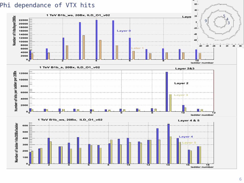
Considering phi dep. Layer 0, ladder 3~5 have ~1/2 hits of 11 ladders. Occupancy would be ~ 3 larger in these ladders

Beam para. 1000GeV-B1b_ws 1000GeV-A1 500 GeV_ws LOIDID w. AntiDID no. DID w. AntiDID w. AntiDID w. AntiDID  

Detector ILD_O1_v02 ILD_00fwp01  Sim. Stat. 20Bx 20Bx 20Bx 7Bx 7Bx  

Layer Hits/BX occ.(%) Hits/BX occ.(%) Hits/BX occ.(%) Hits/BX occ.(%) Hits/BX occ.(%) occ.(%)0 6214 12.84 25821 53.35 2771 5.73 2132 2.93 2679 3.67 3.33 1 3334 6.89 14599 30.16 1525 3.15 1102 1.51 1674 2.30 1.90 2 1143 2.18 788 1.51 519 0.99 349 0.44 335 0.42 0.40 3 663 1.27 567 1.08 328 0.63 223 0.28 287 0.36 0.33 4 317 0.40 342 0.43 162 0.21 91 0.08 69 0.06 0.08 5 272 0.35 333 0.42 129 0.16 90 0.08 62 0.05 0.06

11

TPC hits 1 TeV-B1b_ws: 163k hits/BX (ILD_O1_V02) -A1 : 78k hits/BX (ILD_O1_v02) 500 GeV : 50k hits/BX (ILD_O1_V02) 12k hits/BX (ILD_00fwp01)

1 TeV ~ 3 x 500 GeV hitsILD_O1_V02 ~ 4xILD_00fwp01 geometry problem in ILD_O1_v02 ?

1TeV-B1b_wsILD_O1_v02

500GeVILD_O1_v02

500GeVILD_00fwp01

FTD Hits 1 TeV

  #Hits/BX Ratio

Layer1TeV

B1b_ws0.5TeV

0 0 0  1 0 0  2 876 270 3.24 3 619 191 3.24 4 407 123 3.31 5 202 56 3.59 6 126 37 3.37

(ILD_O1_V02)

BCAL

500GeV

1TeV

Z distribution

Z distribution

∑E/BX=3.33E7

∑E/BX=9.78E7

~2.9 x 500GeV

(ILD_O0_V02)

# Hits

14KILC12 Software Session

Summary

Background hit occupancies were studied with the latest GDE beam parameters for 1 TeV and 500 GeV ILD_O1_v02 ( beam pipe geometry overlaps ), Mokka-07-07-p06

VXD 500 GeV result is consistent with LOI result (assume 4pixels/hit) CMOS like VXD,

Hit occupancy of SimTrackerHit at 1 TeV was about x4 of 500 GeV

Taking into account phi-dependence of hit distribution, the occupancy could be x3 larger

Faster readout is required. FPCCD like VXD ( smaller pixels, inter-pulse readout ),

Occupancies at the inner layers would be higher. TPC, FTD, BCAL : 3~4 times more hits at 1 TeV-B1b 500 GeV ILD_O1_V02 : ~x3 more TPC hits than ILD_00fwp01 Geometry overlaps in beampipe may cause the difference 25 April 2012 Akiya Miyamoto

1525 April 2012 Akiya Miyamoto

KILC12 Software Session

BackupSlides


Recommended