21
1 The Dorr-Oliver Flotation cell Six blade impeller Stator with 4 large blades and 12 small
| Date post: | 29-Dec-2015 |
| Category: |
Documents |
| Upload: | tracey-atkinson |
| View: | 223 times |
| Download: | 2 times |
1
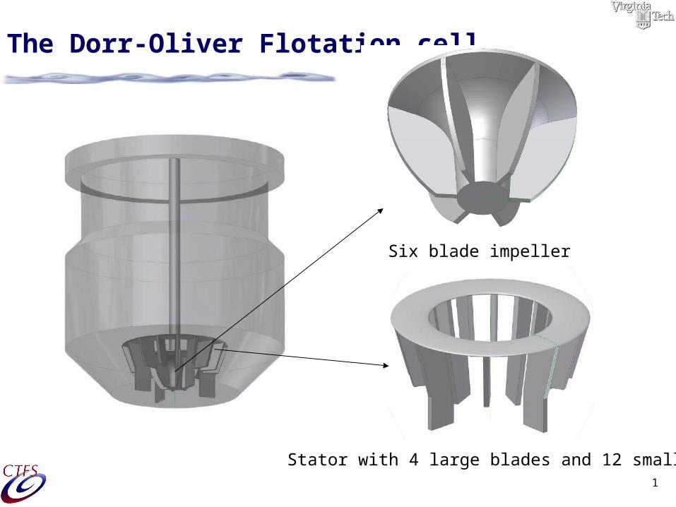
The Dorr-Oliver Flotation cell
Six blade impeller
Stator with 4 large blades and 12 small

2
The three studied Configurations for Re=35000
3cm 1cm 1cm with stator
y
x or r
3
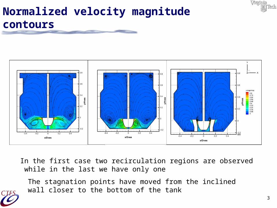
Normalized velocity magnitude contours
In the first case two recirculation regions are observed while in the last we have only one
The stagnation points have moved from the inclined wall closer to the bottom of the tank
4
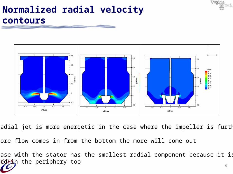
Normalized radial velocity contours
The radial jet is more energetic in the case where the impeller is further up.
The more flow comes in from the bottom the more will come out
The case with the stator has the smallest radial component because it is Blocked in the periphery too
5
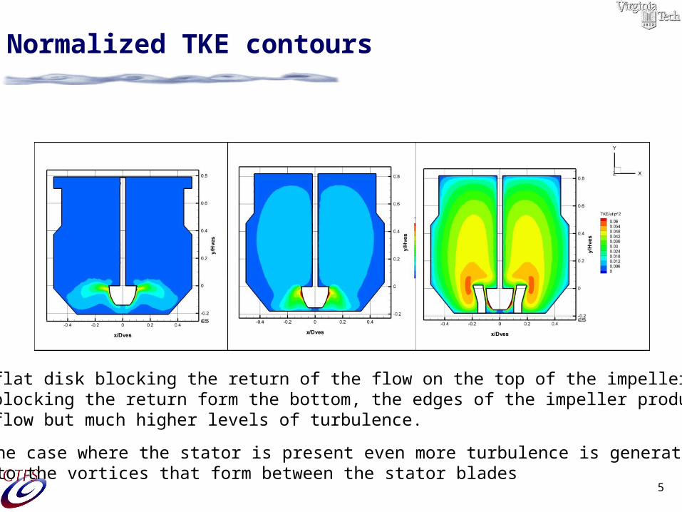
Normalized TKE contours
With a flat disk blocking the return of the flow on the top of the impeller and the ground blocking the return form the bottom, the edges of the impeller produceslower flow but much higher levels of turbulence.
In the case where the stator is present even more turbulence is generated due to the vortices that form between the stator blades
6
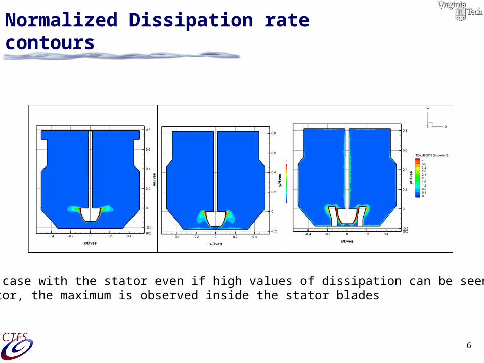
Normalized Dissipation rate contours
For the case with the stator even if high values of dissipation can be seen aroundthe stator, the maximum is observed inside the stator blades
7
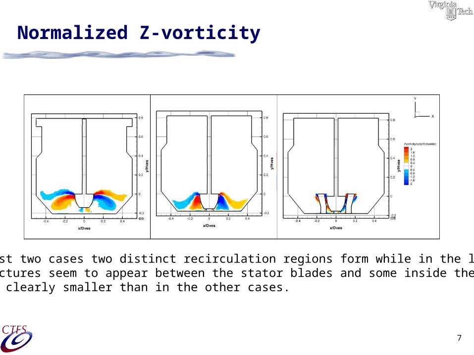
Normalized Z-vorticity
In the first two cases two distinct recirculation regions form while in the latter one small structures seem to appear between the stator blades and some inside the stator but clearly smaller than in the other cases.
8
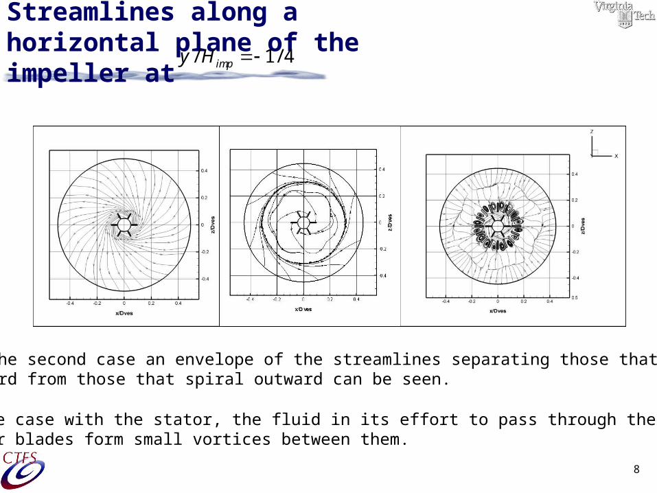
Streamlines along a horizontal plane of the impeller at
/ 1/ 4impy H
/ 1/ 4impy H
In the second case an envelope of the streamlines separating those that spiral inward from those that spiral outward can be seen.
In the case with the stator, the fluid in its effort to pass through thestator blades form small vortices between them.
9
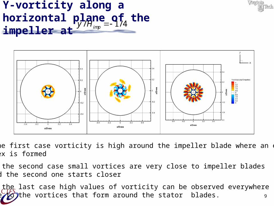
Y-vorticity along a horizontal plane of the impeller at/ 1/ 4impy H
In the first case vorticity is high around the impeller blade where an extended vortex is formed
In the second case small vortices are very close to impeller blades and the second one starts closer
In the last case high values of vorticity can be observed everywhere due to the vortices that form around the stator blades.
10
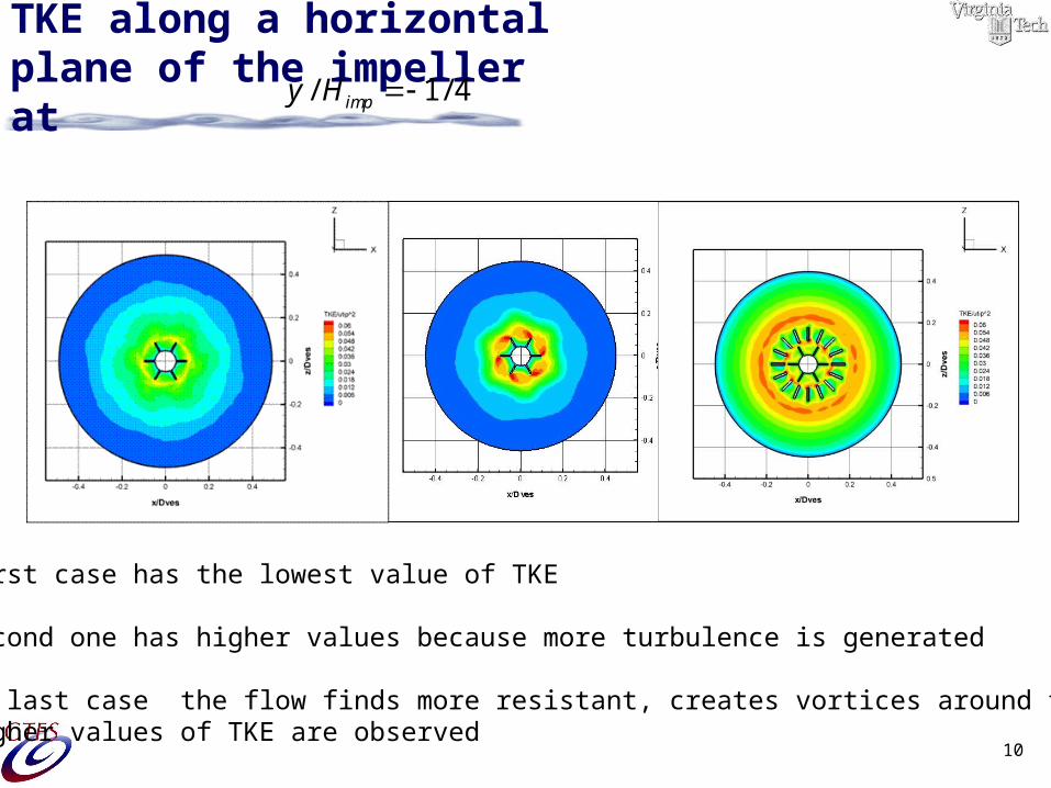
TKE along a horizontal plane of the impeller at/ 1/ 4impy H
The first case has the lowest value of TKE
The second one has higher values because more turbulence is generated
In the last case the flow finds more resistant, creates vortices around the statorAnd higher values of TKE are observed
11
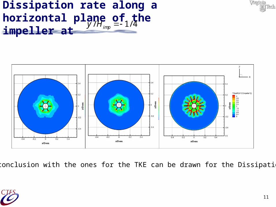
Dissipation rate along a horizontal plane of the impeller at
/ 1/ 4impy H
Similar conclusion with the ones for the TKE can be drawn for the Dissipation rate
12
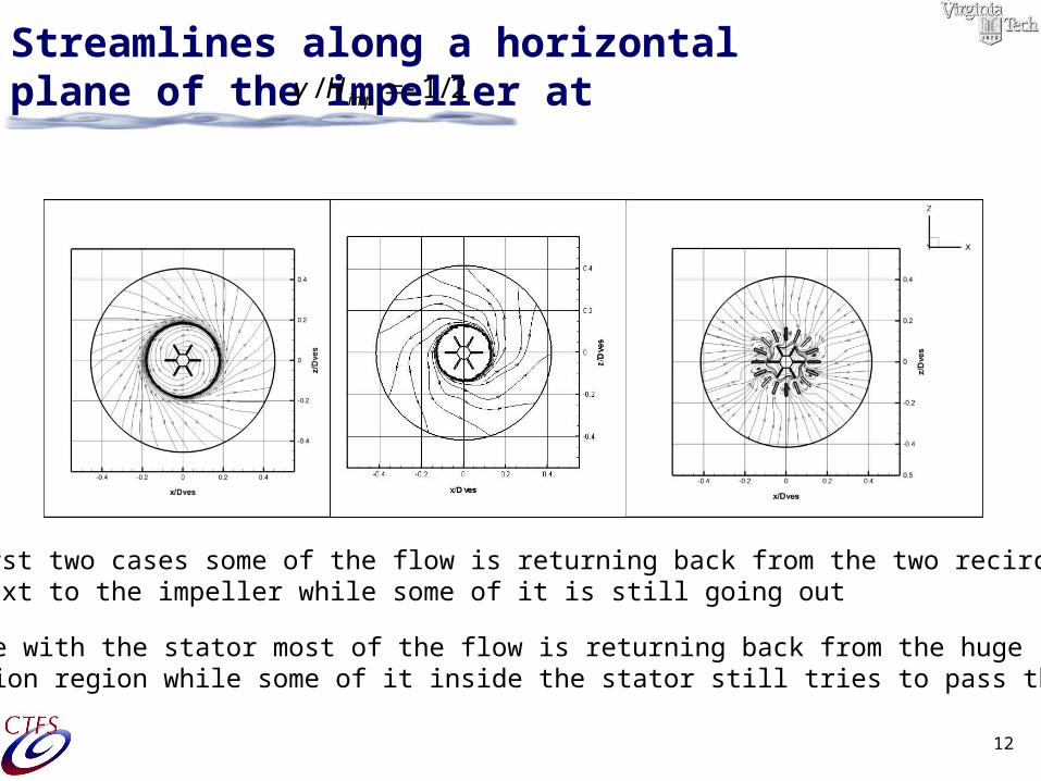
Streamlines along a horizontal plane of the impeller at/ 1/ 2impy H
In the first two cases some of the flow is returning back from the two recirculationregions next to the impeller while some of it is still going out
In the case with the stator most of the flow is returning back from the huge recirculation region while some of it inside the stator still tries to pass through.
13
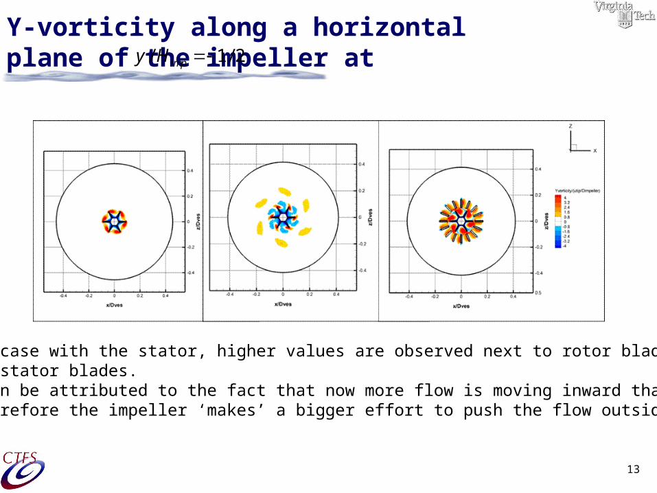
Y-vorticity along a horizontal plane of the impeller at/ 1/ 2impy H
In the case with the stator, higher values are observed next to rotor blades than in the stator blades. This can be attributed to the fact that now more flow is moving inward than outwardand therefore the impeller ‘makes’ a bigger effort to push the flow outside.
14
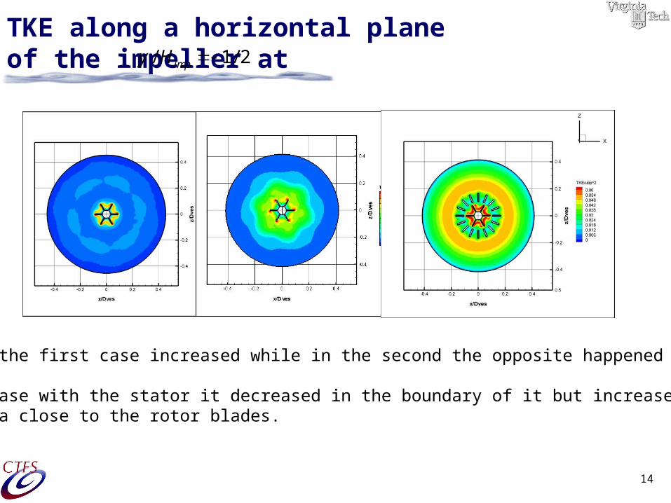
TKE along a horizontal plane of the impeller at
TKE for the first case increased while in the second the opposite happened
In the case with the stator it decreased in the boundary of it but increased in the area close to the rotor blades.
/ 1/ 2impy H
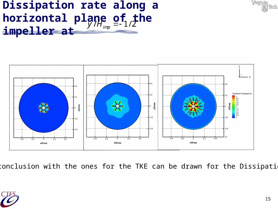
15
Dissipation rate along a horizontal plane of the impeller at
/ 1/ 2impy H
Similar conclusion with the ones for the TKE can be drawn for the Dissipation rate
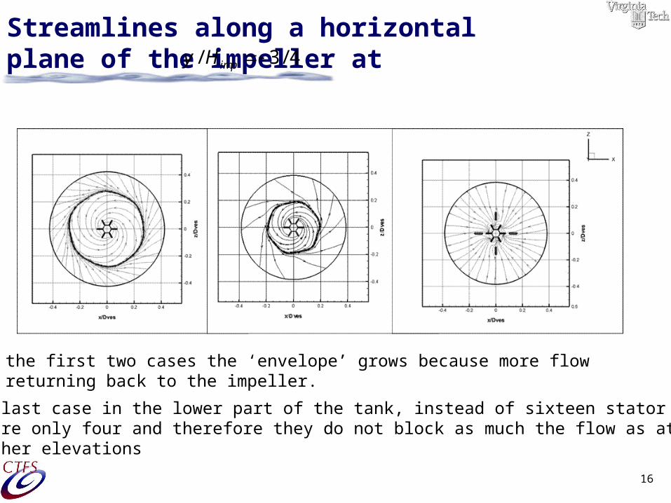
16
Streamlines along a horizontal plane of the impeller at/ 3 / 4impy H
In the first two cases the ‘envelope’ grows because more flow is returning back to the impeller.
In the last case in the lower part of the tank, instead of sixteen stator blades there are only four and therefore they do not block as much the flow as at the higher elevations
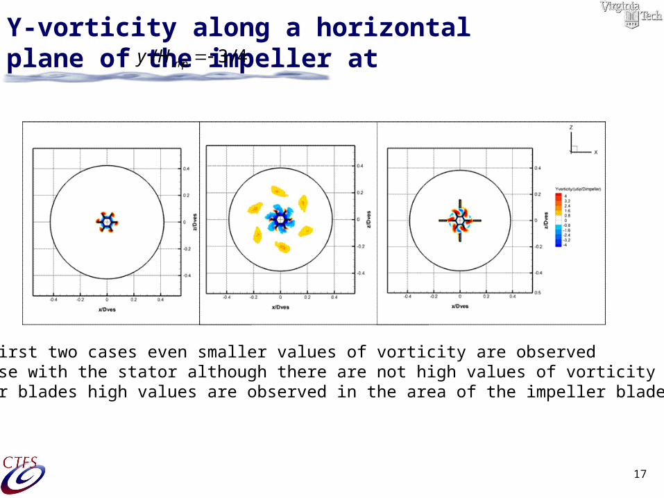
17
Y-vorticity along a horizontal plane of the impeller at/ 3 / 4impy H
For the first two cases even smaller values of vorticity are observed In the case with the stator although there are not high values of vorticity between the stator blades high values are observed in the area of the impeller blades
18
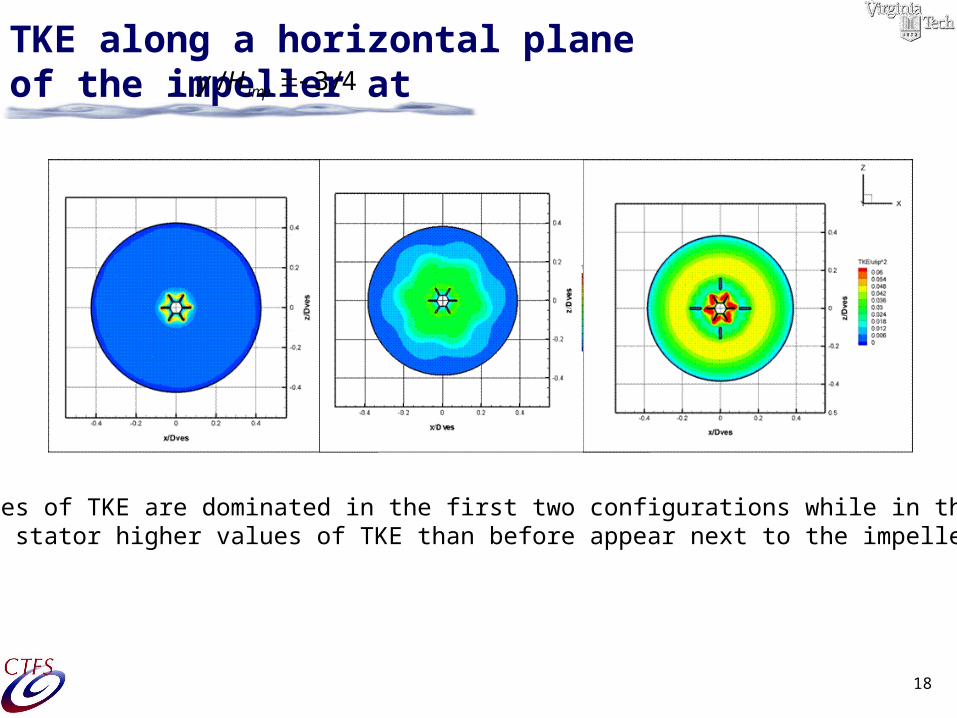
TKE along a horizontal plane of the impeller at
Low values of TKE are dominated in the first two configurations while in the one with the stator higher values of TKE than before appear next to the impeller blades.
/ 3 / 4impy H
19
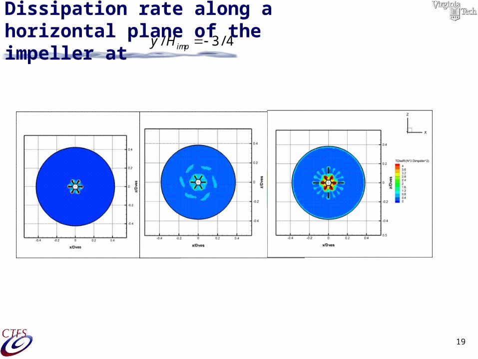
Dissipation rate along a horizontal plane of the impeller at
/ 3 / 4impy H
20
Conclusions
The turbulent kinetic energy and dissipation have the highest values
in the immediate neighborhood of the impeller Good agreement with the experimental data is succeed
Most of the times the Standard k-e model predicts better the flow velocities and the turbulent quantities while in some others has poor performance and the RNG k-e is better
In the case of the low configuration model:
there is a strong tendency to skew the contours downward the dominant downward flow is diverting the jet-like flow that leaves the tip of the impeller downward, and it convects with the turbulent features of the flow. The axial component of the velocity has high values
21
Future Work
Experimental predictions for the Dorr-Oliver Flotation cell
Comparisons of the studied cases with the experiments
More Re numbers and clearances for the Dorr-Oliver Cell
Higher Re numbers for both Tanks (100000-300000)
Unsteady calculations
Extension to two-phase or three phase flows


