65
Slide 1 / 65 1 The length and radius of an aluminum wire is quadrupled. By which factor does the resistance change? A 2 B 1/2 C 1/4 D 1

Slide 1 / 65
1 The length and radius of an aluminum wire is quadrupled. By which factor does the resistance change?
A 2
B 1/2
C 1/4
D 1

Slide 2 / 65
2 A copper wire has a length L and cross-sectional area A. What happens to the resistivity of the wire if the length is doubled and cross-sectional area halved?
A Four times as large
B Stays the same
C Half as large
D Quarter as large

Slide 3 / 65
3 Which circuit has greater resistance between the terminals?
A
B
C
D

Slide 4 / 65
4 Which circuits have the same resistance between the terminals?
A A and B
B B and C
C C and D
D A and D

Slide 5 / 65
5 In the circuit shown, what is the value of the net resistance?
A 0.75 Ω
B 4.5 Ω
C 6 Ω
D 13 Ω

Slide 6 / 65
6 What is the current in 4 - Ω resistor?
A 2 A
B 3 A
C 9A
D 12 A

Slide 7 / 65
7 What is the voltage between points L and M?
A 2 V
B 4 V
C 8 V
D 12 V

Slide 8 / 65
8 A lamp L1, a voltmeter V, an ammeter A, and a battery with zero internal resistance are connected as shown above. Connecting another lamp L2 in series with the first lamp as shown by the dashed lines would
A Increase the ammeter reading
B Increase the voltmeter reading
C Decrease the ammeter reading
D Decrease the voltmeter reading

Slide 9 / 65
9 The four resistors shown below have the lengths and cross-sectional areas indicated and are made of material with the same resistivity. Which has the smallest resistance?
A
B
C
D

Slide 10 / 65
10 The circuit shown above left is made up of a variable resistor and a battery with negligible internal resistance. A graph of the power P dissipated in the resistor as a function of the current I supplied by the battery is given above right. What is the emf of the battery?
A 0.125 V
B 5 V
C 8 V
D 40 V

Slide 11 / 65
11 The total equivalent resistance of the circuit shown on the diagram is:
A 2 Ω
B 6 Ω
C 9 Ω
D 18 Ω

Slide 12 / 65
12 A heating spiral of resistance R converts elec-trical energy into thermal energy that is transferred to the liquid in which the spiral is immersed. If the voltage across the spiral is V, the thermal energy trans-ferred to the liquid in time t is:
A Vrt
B V2Rt
C VR2t
D V2t/R

Slide 13 / 65
13 In the circuit two identical resistors R are connected in series with 8-W resistor and 12- V battery. What is the value of R if the current in the circuit I = 1 A?
A 2 Ω
B 4 Ω
C 8 Ω
D 12 Ω

Slide 14 / 65
14 Questions 14-16 relate to the following circuit diagram which shows a battery with an internal resistance of 2.0 ohms connected to an 8-ohm and a 10-ohm resistor in series. The current in the 10-ohm resistor is 0.2 amperes. What is the emf of the battery?
A 0.4 V
B 3.6 V
C 4 V
D 12 V

Slide 15 / 65
15 Questions 14-16 relate to the following circuit diagram which shows a battery with an internal resistance of 2.0 ohms connected to an 8-ohm and a 10-ohm resistor in series. The current in the 10-ohm resistor is 0.2 amperes. What is the potential difference across the terminals A and B of the battery?
A 1.2 V
B 2.4 V
C 3.6 V
D 12.2 V

Slide 16 / 65
16 Questions 14-16 relate to the following circuit diagram which shows a battery with an internal resistance of 2.0 ohms connected to an 8-ohm and a 10-ohm resistor in series. The current in the 10-ohm resistor is 0.2 amperes. What power is dissipated by the 2-ohm internal resistance of the battery?
A 0.08 W
B 0.8 W
C 1.2 W
D 6.5 W

Slide 17 / 65
17 In the diagrams above, resistors R1 and R2 are shown in two different connections to the same source of emf e that has no internal resistance. How does the power dissipated by the resistors in these two cases compare?
A It is greater for the series connection.
B It is greater for the parallel connection.
C It is the same for both connections.
D One must know the values of R1 and R2 to know which is greater.

Slide 18 / 65
18 The product 3 amperes x 3 volts x 3 seconds is equal to
A 27 C
B 27 N
C 27 J
D 27 W

Slide 19 / 65
19 The electrical resistance of the part of the circuit shown between point X and point Y is
A 1.4 ohms
B 2.5 ohms
C 6.2 ohms
D 10 ohms

Slide 20 / 65
20 When there is a steady current in the circuit, the amount of charge passing a point per unit of time is:
A the same everywhere in the circuit
B greater at point X than at point Y
C greater in the 2 ohm resistor than in the 5 ohm resistor
D the same in the 2 ohm resistor and in the 5 ohm resistor

Slide 21 / 65
21 A certain coffeepot draws 2.0 A of current when it is operated on 110 V household lines. If electrical energy costs 10 cents per kilowatt-hour, how much does it cost to operate the coffeepot for 5 hours?
A 2.4 cents
B 4.8 cents
C 8.0 cents
D 11 cents

Slide 22 / 65
22 Five identical light bulbs are connected to a 120 V power supply. Each light bulb has a resistance of 15 Ω. The switch is closed. What is the net resistance of the circuit?
A 3 Ω
B 30.1 Ω
C 40 Ω
D 75 Ω

Slide 23 / 65
23 Five identical light bulbs are connected to a 120 V power supply. Each light bulb has a resistance of 15 Ω. The switch is closed. What is the current in the light bulb L1?
A 1.6 A
B 3 A
C 8 A
D 40 A

Slide 24 / 65
24 Five identical light bulbs are connected to a 120 V power supply. Each light bulb has a resistance of 15 Ω. The switch is closed. Which light bulb or bulbs could burn out without causing any others to go out?
A Only L1
B Only L2
C Only L4
D Only L5

Slide 25 / 65
25 A circuit, shown above, has three resisters R-1 = 60Ω, R2 = 30Ω, and R3 = 20Ω, an internal resistance r = 4Ω, and a battery 120V. What is the relationship between the three labeled currents?
A I1 =I2 < I < I3
B I1 + I2 + I3 = I
C I2 > I1 > I3 > I
D I1 + I2 = I3 = I

Slide 26 / 65
26 A circuit, shown above, has three resisters R-1 = 60Ω, R2 = 30Ω, and R3 = 20Ω, an internal resistance r = 4Ω, and a battery 120V. If V1 represents the potential difference across the first resistor, V2 across the second resistor, V3 across the third resistor and V the terminal voltage in the battery. What is the relationship between the V1, V2, V3, and V?
A V1 = V2 = V – V3
B V1 + V2 + V3 = V
C V1 = V2 = V3 < V
D V > V3 > V2 > V1

Slide 27 / 65
27 A circuit, shown above, has three resisters R-1 = 60Ω, R2 = 30Ω, and R3 = 20Ω, an internal resistance r = 4Ω, and a battery 120V. What is the ratio of current I1 in resistor R1 to the current in I2 in resistor R2?
A B C D

Slide 28 / 65
28 A battery has an emf of ε and an internal resistance of r. What resistance R, when connected across the terminals of the battery will make the terminal voltage to be ½ ε?
A ½ r
B 2r
C r
D 4r

Slide 29 / 65
29 Multi-correct Section: For each question or incomplete statement, two of the answers are correct. For each questions you must select both answers. In reference to the circuit above, which of the follow statements are true? Choose two answers.
A The current in R1 must be the same as the current in R2.
B The current in R3 must be the same as the current in the battery.
C The voltage across R1 must be the same as the voltage across R2.
D The voltage across R3 must be the same as the voltage across the battery.

Slide 30 / 65
30 For each question or incomplete statement, two of the answers are correct. For each questions you must select both answers. A single resistor is connected across the terminals of a battery. Which of the following will leave the power output unaffected? Choose two answers.
A Reducing both the resistance and the voltage by a factor of 4.
B Reducing the resistance by a factor of 4 and the voltage by a factor of 2.
C Doubling both the resistance and the voltage.
D Doubling the voltage and increasing the resistance by a factor of 4.

Slide 31 / 65
31 Multi-correct Section: For each question or incomplete statement, two of the answers are correct. For each questions you must select both answers. The diagrams above so four light bulbs of the same type. Two are in series and two are in parallel. Which of the following statements are true? Choose two answers.
A The light bulbs in the series circuit are brightest since they get the total current.
B The light bulbs in the parallel circuit draw more power than in the series circuit.
C The series circuit has more total resistance than the parallel circuit.
D The parallel circuit has the less total current than the series circuit.

Slide 32 / 65
32 Multi-correct Section: For each question or incomplete statement, two of the answers are correct. For each questions you must select both answers. The following diagrams show resistors in four different circuits. Which two have the same total resistance? Choose two answers.
A
B
C
D

Slide 33 / 65
1. A physics student has an assignment to make an electrical heating system with the set of materials listed below:
a. In a space below draw a diagram showing all the elements connected in one electrical circuit that can provide the maximum rate of heat produced. Use two meters in your circuit, they will help to measure the heat rate.The battery has an emf of 12 V and an internal resistance of 0.5 Ω and each heating coil has a resistance of 17.3 Ω.
b. When the switch is closed, what is the current running through the battery?
c. What is the terminal voltage on the battery?
d. What is the rate of energy delivered by the heating system?
e. If the switch is closed for 5 min, what is the total energy dissipated in the coils?

Slide 34 / 65
1. A physics student has an assignment to make an electrical heating system with the set of materials listed below:
a. In a space below draw a diagram showing all the elements connected in one electrical circuit that can provide the maximum rate of heat produced. Use two meters in your circuit, they will help to measure the heat rate.

Slide 35 / 65
1. A physics student has an assignment to make an electrical heating system with the set of materials listed below:
The battery has an emf of 12 V and an internal resistance of 0.5 Ω and each heating coil has a resistance of 17.3 Ω.
b. When the switch is closed, what is the current running through the battery?

Slide 36 / 65
1. A physics student has an assignment to make an electrical heating system with the set of materials listed below:
The battery has an emf of 12 V and an internal resistance of 0.5 Ω and each heating coil has a resistance of 17.3 Ω.
c. What is the terminal voltage on the battery?

Slide 37 / 65
1. A physics student has an assignment to make an electrical heating system with the set of materials listed below:
The battery has an emf of 12 V and an internal resistance of 0.5 Ω and each heating coil has a resistance of 17.3 Ω.
d. What is the rate of energy delivered by the heating system?

Slide 38 / 65
1. A physics student has an assignment to make an electrical heating system with the set of materials listed below:
The battery has an emf of 12 V and an internal resistance of 0.5 Ω and each heating coil has a resistance of 17.3 Ω.
e. If the switch is closed for 5 min, what is the total energy dissipated in the coils?

Slide 39 / 65
2. An electric motor in a toy car can operate when connected to a 6 V battery and has a current of 0.5 A. A physics student wants to run the toy car but unfortunately he could find a 12 V battery in the physics lab. The student also found a box with a set of five 6-Ω resistors.
a. Use given materials design an electric circuit in which the electric motor will operate properly.
i. Draw the circuit including all devices.
ii. Explain your reasoning in designing this particular circuit.
b. Calculate the net resistance of the circuit.
c. Calculate the power dissipated in the circuit.

Slide 40 / 65
2. An electric motor in a toy car can operate when connected to a 6 V battery and has a current of 0.5 A. A physics student wants to run the toy car but unfortunately he could find a 12 V battery in the physics lab. The student also found a box with a set of five 6-Ω resistors.
a. Use given materials design an electric circuit in which the electric motor will operate properly.
i. Draw the circuit including all devices.
ii. Explain your reasoning in designing this particular circuit.

Slide 41 / 65
2. An electric motor in a toy car can operate when connected to a 6 V battery and has a current of 0.5 A. A physics student wants to run the toy car but unfortunately he could find a 12 V battery in the physics lab. The student also found a box with a set of five 6-Ω resistors.
b. Calculate the net resistance of the circuit.
c. Calculate the power dissipated in the circuit.

Slide 42 / 65
2. An electric motor in a toy car can operate when connected to a 6 V battery and has a current of 0.5 A. A physics student wants to run the toy car but unfortunately he could find a 12 V battery in the physics lab. The student also found a box with a set of five 6-Ω resistors.
c. Calculate the power dissipated in the circuit.

Slide 43 / 65
3. Three light bulbs are connected in the circuit show on the diagram. Each light bulb can develop a maximum power of 75 W when connected to a 120-V power supply. The circuit of three light bulbs is connected to a 120 V power supply.
a. What is the resistance of the circuit?
b. What is the power dissipated by the circuit?
c. How would you compare this power to the power when all bulbs are connected in parallel?
d. What is the current in light bulb L1?
e. What is the voltage across light bulb L1?
f. What is the voltage across light bulb L2?

Slide 44 / 65
3. Three light bulbs are connected in the circuit show on the diagram. Each light bulb can develop a maximum power of 75 W when connected to a 120-V power supply. The circuit of three light bulbs is connected to a 120 V power supply.
a. What is the resistance of the circuit?

Slide 45 / 65
3. Three light bulbs are connected in the circuit show on the diagram. Each light bulb can develop a maximum power of 75 W when connected to a 120-V power supply. The circuit of three light bulbs is connected to a 120 V power supply.
b. What is the power dissipated by the circuit?

Slide 46 / 65
3. Three light bulbs are connected in the circuit show on the diagram. Each light bulb can develop a maximum power of 75 W when connected to a 120-V power supply. The circuit of three light bulbs is connected to a 120 V power supply.
c. How would you compare this power to the power when all bulbs are connected in parallel?

Slide 47 / 65
3. Three light bulbs are connected in the circuit show on the diagram. Each light bulb can develop a maximum power of 75 W when connected to a 120-V power supply. The circuit of three light bulbs is connected to a 120 V power supply.
d. What is the current in light bulb L1?

Slide 48 / 65
3. Three light bulbs are connected in the circuit show on the diagram. Each light bulb can develop a maximum power of 75 W when connected to a 120-V power supply. The circuit of three light bulbs is connected to a 120 V power supply.
e. What is the voltage across light bulb L1?

Slide 49 / 65
3. Three light bulbs are connected in the circuit show on the diagram. Each light bulb can develop a maximum power of 75 W when connected to a 120-V power supply. The circuit of three light bulbs is connected to a 120 V power supply.
f. What is the voltage across light bulb L2?
Slide 50 / 65
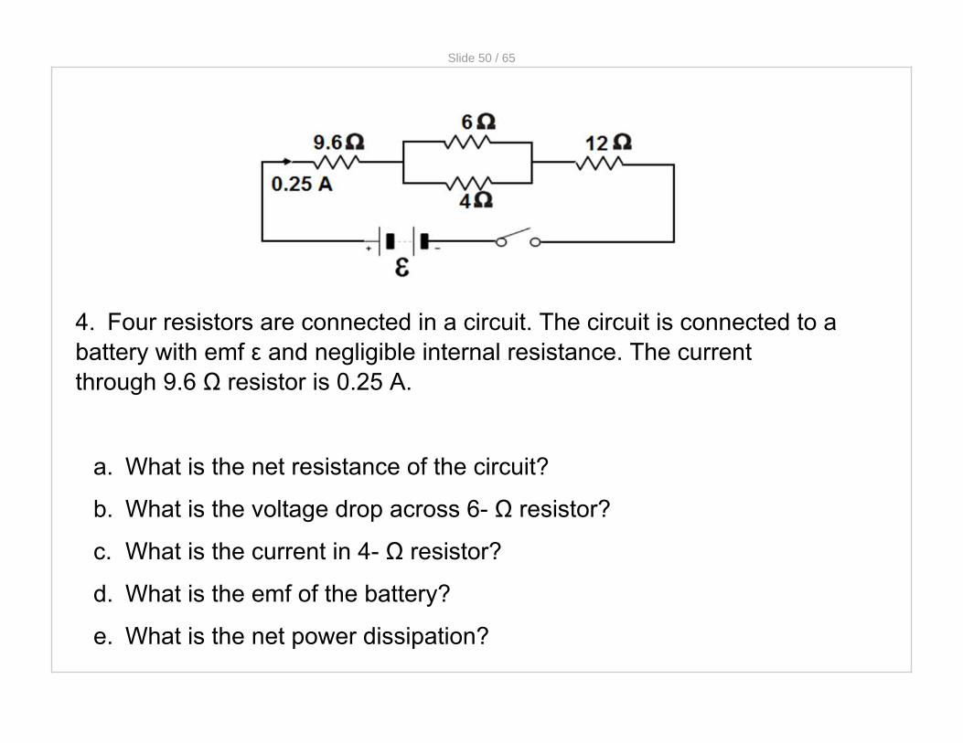
4. Four resistors are connected in a circuit. The circuit is connected to a battery with emf ε and negligible internal resistance. The current through 9.6 Ω resistor is 0.25 A.
a. What is the net resistance of the circuit?
b. What is the voltage drop across 6- Ω resistor?
c. What is the current in 4- Ω resistor?
d. What is the emf of the battery?
e. What is the net power dissipation?

Slide 51 / 65
4. Four resistors are connected in a circuit. The circuit is connected to a battery with emf ε and negligible internal resistance. The current through 9.6 Ω resistor is 0.25 A.
a. What is the net resistance of the circuit?

Slide 52 / 65
4. Four resistors are connected in a circuit. The circuit is connected to a battery with emf ε and negligible internal resistance. The current through 9.6 Ω resistor is 0.25 A.
b. What is the voltage drop across 6- Ω resistor?

Slide 53 / 65
4. Four resistors are connected in a circuit. The circuit is connected to a battery with emf ε and negligible internal resistance. The current through 9.6 Ω resistor is 0.25 A.
c. What is the current in 4- Ω resistor?

Slide 54 / 65
4. Four resistors are connected in a circuit. The circuit is connected to a battery with emf ε and negligible internal resistance. The current through 9.6 Ω resistor is 0.25 A.
d. What is the emf of the battery?

Slide 55 / 65
4. Four resistors are connected in a circuit. The circuit is connected to a battery with emf ε and negligible internal resistance. The current through 9.6 Ω resistor is 0.25 A.
e. What is the net power dissipation?

Slide 56 / 65
5. Five resistors are connected to a battery with an emf of 12 V and an internal resistance of 1 Ω.
a. Calculate the external resistance of the circuit.
b. Calculate the current in the battery.
c. Calculate the terminal voltage of the battery.
d. Calculate the power dissipation in the 3- Ω resistor.
e. Calculate the power dissipation in the internal resistance.

Slide 57 / 65
5. Five resistors are connected to a battery with an emf of 12 V and an internal resistance of 1 Ω.
a. Calculate the external resistance of the circuit.

Slide 58 / 65
5. Five resistors are connected to a battery with an emf of 12 V and an internal resistance of 1 Ω.
b. Calculate the current in the battery.

Slide 59 / 65
5. Five resistors are connected to a battery with an emf of 12 V and an internal resistance of 1 Ω.
c. Calculate the terminal voltage of the battery.

Slide 60 / 65
5. Five resistors are connected to a battery with an emf of 12 V and an internal resistance of 1 Ω.
d. Calculate the power dissipation in the 3- Ω resistor.

Slide 61 / 65
5. Five resistors are connected to a battery with an emf of 12 V and an internal resistance of 1 Ω.
e. Calculate the power dissipation in the internal resistance.

Slide 62 / 65
6. Students in the physics lab have a 30W light bulb and a 40W light bulb. Both are meant to be used in a 120V outlet. They experiment connecting the bulbs in series and in parallel to 120V.
The first student thinks that the 40W bulb will be brighter than the 30W bulb regardless of the connection since brightness depends on the power output and the 40W bulb has a lower resistance therefore a higher power output.
The second student thinks that the 30W bulb will be brighter in either case because, for the same current, the greater the resistance, the greater the power output and the 30W bulb has the greater resistance.
a. Ignoring if the prediction is correct, what aspect of the first student’s argument is correct and incorrect? Explain your reasoning.
b. Ignoring if the prediction is correct, what aspect of the second student’s argument is correct and incorrect? Explain your reasoning.
c. Rank the following light bulbs from 1 to 4, 1 being the brightest and 4 being the least bright. Justify your answer.

Slide 63 / 65
6. Students in the physics lab have a 30W light bulb and a 40W light bulb. Both are meant to be used in a 120V outlet. They experiment connecting the bulbs in series and in parallel to 120V.
The first student thinks that the 40W bulb will be brighter than the 30W bulb regardless of the connection since brightness depends on the power output and the 40W bulb has a lower resistance therefore a higher power output.
The second student thinks that the 30W bulb will be brighter in either case because, for the same current, the greater the resistance, the greater the power output and the 30W bulb has the greater resistance.
a. Ignoring if the prediction is correct, what aspect of the first student’s argument is correct and incorrect? Explain your reasoning.

Slide 64 / 65
6. Students in the physics lab have a 30W light bulb and a 40W light bulb. Both are meant to be used in a 120V outlet. They experiment connecting the bulbs in series and in parallel to 120V.
The first student thinks that the 40W bulb will be brighter than the 30W bulb regardless of the connection since brightness depends on the power output and the 40W bulb has a lower resistance therefore a higher power output.
The second student thinks that the 30W bulb will be brighter in either case because, for the same current, the greater the resistance, the greater the power output and the 30W bulb has the greater resistance.
b. Ignoring if the prediction is correct, what aspect of the second student’s argument is correct and incorrect? Explain your reasoning.

Slide 65 / 65
6. Students in the physics lab have a 30W light bulb and a 40W light bulb. Both are meant to be used in a 120V outlet. They experiment connecting the bulbs in series and in parallel to 120V.
The first student thinks that the 40W bulb will be brighter than the 30W bulb regardless of the connection since brightness depends on the power output and the 40W bulb has a lower resistance therefore a higher power output.
The second student thinks that the 30W bulb will be brighter in either case because, for the same current, the greater the resistance, the greater the power output and the 30W bulb has the greater resistance.
c. Rank the following light bulbs from 1 to 4, 1 being the brightest and 4 being the least bright. Justify your answer.
_____ the 30W bulb in parallel
_____ the 40W bulb in parallel
_____ the 30W bulb in series
_____ the 40W bulb in series


