46
1 THE MASTERWORKS OF GEOTECHNICAL ENGINEERING

1
THE MASTERWORKSOF GEOTECHNICALENGINEERING

2 3
THE MASTERWORKS
OF GEOTECHNICALENGINEERING

4 5
THE MASTERWORKS
OF GEOTECHNICALENGINEERING
Soil Structure Interaction Tunneling / Underground Space Excavation / Retaining wall Slope Stability / Dam / Embankment
06 32 54 76
Contents

6
SOIL STRUCTURE INTERACTION
Analysis methods
Linear / Nonlinear Static Analysis
Construction Stage Analysis
Fully-Coupled Stress-Seepage Analysis
* Dynamic Analysis (Seismic Capacity)
Design considerations
Interface between structures and surrounded soils
Pile, Reinforcement design / Skin friction / End bearing
Differential settlements / Lateral movement
Effect on adjacent structures

8 9Soil Structure Interaction
Dubai Tower in QatarDoha, Qatar
Slope Stability / Dam / Embankment
Owner
Engineering Consultant
General Contractor
Architecture
Project Type
Size of the Structure
Main features in modelling
Sama Dubai (Dubai International Properties)
Hyder Consulting
Al Habtoor - Al Jaber Joint Venture
RMJM
Mixed-Use Building
439m Height (88-Story)
- Piled - raft foundation for high - rise building
Pile forces and bending moments)- Analysis results for design (Settlements, Raft forces and bending moments,
Description on this project The proposed development for the Dubai Tower project comprises the construction of an approximately 80 floor high-rise tower with a mezzanine, ground floor and five basement levels. It will be the tallest structure in Qatar when it is complete. The tower was founded on soft sand and required the design of a piled raft in a 3D finite element model to fully understand the behavior.
Tunneling / Underground Space Excavation / Retaining wall

10 11Tunneling / Underground Space Excavation / Retaining wallSoil Structure Interaction
Pentominium Residential Development in UAEDubai, United Arab Emirates
Owner
General Contractor
Engineering Consultant
Construction Period
Project Type
Size of the Structure
Main features in modelling
Trident International Holdings
Arabian Construction Company - Hitachi Plant Technologies
Hyder Consulting
Under Construction
Residential Building
516m Height (122-Story)
- Piled - raft foundation for high - rise building- Analysis results for design (Settlements, raft forces and bending moments, pile forces and bending moments)
The Pentominium Residential Development is located on the west side of the creek in Dubai. The development comprises the construction of an approximately 120 story high-rise tower inter–linked by low level podium structure housing up to 7 basement levels. The Pentominium Tower will be founded on a piled raft and required a 3D finite element model to fully understand the behavior of the foundation interaction with surrounding soil.
Slope Stability / Dam / Embankment
Description on this project
12 13Soil Structure Interaction
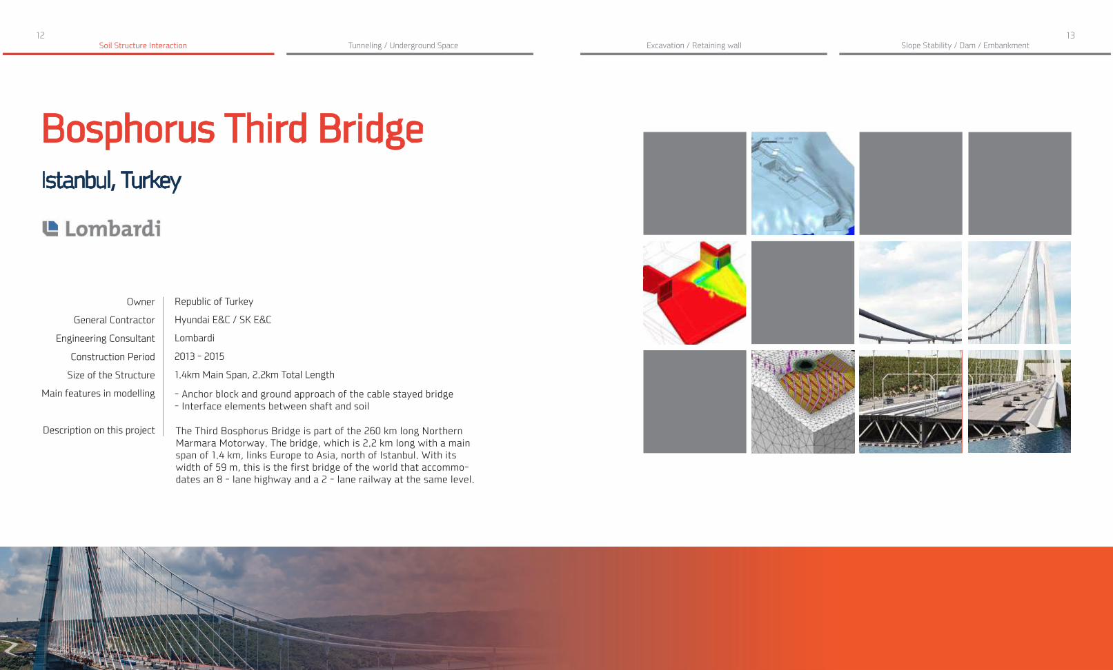
Bosphorus Third BridgeIstanbul, Turkey
Slope Stability / Dam / Embankment
Republic of Turkey
Hyundai E&C / SK E&C
Lombardi
2013 - 2015
1.4km Main Span, 2.2km Total Length
- Anchor block and ground approach of the cable stayed bridge- Interface elements between shaft and soil
The Third Bosphorus Bridge is part of the 260 km long Northern Marmara Motorway. The bridge, which is 2.2 km long with a main span of 1.4 km, links Europe to Asia, north of Istanbul. With its width of 59 m, this is the first bridge of the world that accommo-dates an 8 - lane highway and a 2 - lane railway at the same level.
Owner
General Contractor
Engineering Consultant
Construction Period
Size of the Structure
Main features in modelling
Description on this project
Tunneling / Underground Space Excavation / Retaining wall

14 15Tunneling / Underground Space Excavation / Retaining wallSoil Structure Interaction
Foundation of Sugar SiloGostyn, Poland
Engineering Consultant
Construction Period
Project Type
Size of the Structure
Main features in modelling
Description on this project
GT Projekt
2012 - 2013
Silo Foundation
50m Diameter, 70m Height, 80,000 tons Capacity
- Linear static analysis with construction stages- Hardening soil material and soil - pile interface elements
Special solution was needed for the largest sugar silo in Poland because it would sit on soft soil. It was determined that more than 1,000 displacement piles was needed for the foundation following the design with advanced analysis.
Slope Stability / Dam / Embankment
16 17Tunneling / Underground Space Excavation / Retaining wallSoil Structure Interaction
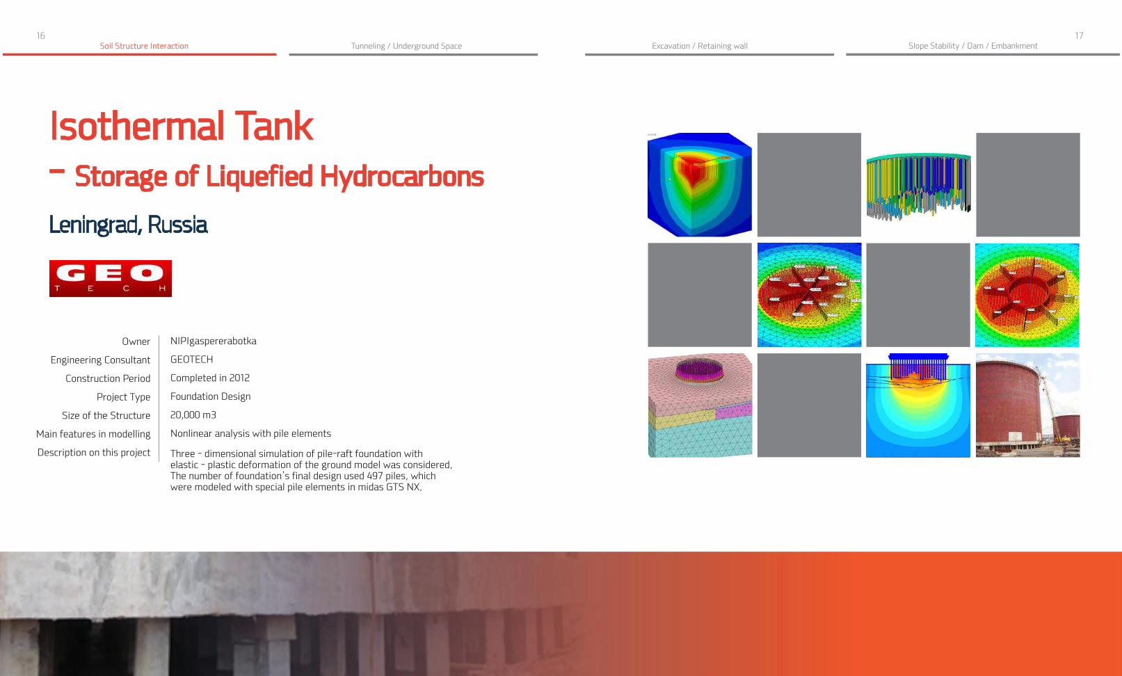
Isothermal Tank- Storage of Liquefied Hydrocarbons
Leningrad, Russia
Owner
Engineering Consultant
Construction Period
Project Type
Size of the Structure
Main features in modelling
Description on this project
NIPIgaspererabotka
GEOTECH
Completed in 2012
Foundation Design
20,000 m3
Nonlinear analysis with pile elements
Three - dimensional simulation of pile-raft foundation with elastic - plastic deformation of the ground model was considered. The number of foundation’s final design used 497 piles, which were modeled with special pile elements in midas GTS NX.
Slope Stability / Dam / Embankment

18 19Tunneling / Underground Space Excavation / Retaining wallSoil Structure Interaction
Bridge on the River Rudavoi - Cortina d’AmpezzoBelluno, Italy
Engineering Consultant
Size of the Structure
Main features in modelling
Description on this project
ULMA Construction
180m Total Length
- Construction stage analysis- Stability analysis for the pier foundation of bridge
After the pier construction, the bridge was completed in three stages. The 70m long stretch between the abutment and the pier was built with horizontal beam - based formwork and full shoring. After concrete hardening and falsework removal, the same material was used in a symmetrical manner between the abutment and the pier on the other side of the bridge. A high capacity shoring tower on a temporary footing supports the central part of the bridge (40m).
Slope Stability / Dam / Embankment
20 21Tunneling / Underground Space Excavation / Retaining wallSoil Structure Interaction
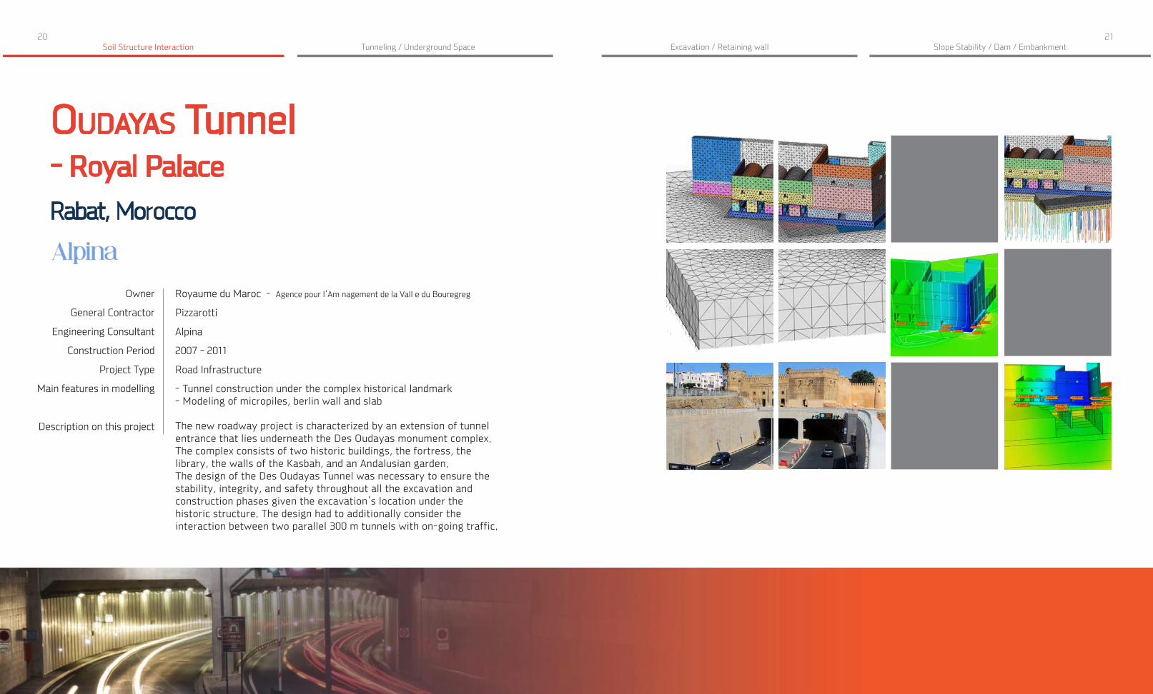
Oudayas Tunnel- Royal Palace
Rabat, Morocco
Owner
General Contractor
Engineering Consultant
Construction Period
Project Type
Main features in modelling
Description on this project
Royaume du Maroc - Agence pour l’Am nagement de la Vall e du Bouregreg
Pizzarotti
Alpina
2007 - 2011
Road Infrastructure
- Tunnel construction under the complex historical landmark- Modeling of micropiles, berlin wall and slab
The new roadway project is characterized by an extension of tunnel entrance that lies underneath the Des Oudayas monument complex. The complex consists of two historic buildings, the fortress, the library, the walls of the Kasbah, and an Andalusian garden. The design of the Des Oudayas Tunnel was necessary to ensure the stability, integrity, and safety throughout all the excavation and construction phases given the excavation’s location under the historic structure. The design had to additionally consider the interaction between two parallel 300 m tunnels with on-going traffic.
Slope Stability / Dam / Embankment

22 23Tunneling / Underground Space Excavation / Retaining wallSoil Structure Interaction
Soil Structure InteractionDifferential SettlementThe complex consists of four buildings with 22 above ground and 2 underground floors. The foundations are monolithic reinforced concrete slabs. The differential settlement under the applied load and the superstructure were calculated considering the nonlinearity of the soil and interaction with the foundation.
Slope Stability / Dam / Embankment
Soil Structure InteractionDifferential Settlement
Calculate overall deformations and the member forces of pile foundations, and the effect on existing community and school buildings.
This is to ensure the safety of existing community and schools. The high-rise building has a dimension of 29 x 70m and 108m in height.

24 25Soil Structure Interaction
Soil Structure InteractionDifferential SettlementFull soil structure interaction analysis was used to determine the differential settlement considering the nonlinearity of each soil layer. The superstructure was created with Autodesk Revit and then transferred to MIDAS while the strata data were imported from Excel tables with boring hole data.
Slope Stability / Dam / Embankment
Soil Structure InteractionFoundation Design
In this project, the combinations of loads and the impacts caused by an earthquake were considered in the foundation design. Bored piles were modeled by 28m
long beam rods connected to the surrounded soil with pile interface elements.
Tunneling / Underground Space Excavation / Retaining wall

26 27Tunneling / Underground Space Excavation / Retaining wallSoil Structure Interaction
Soil Structure InteractionDifferential SettlementGiven the location’s soft soil and high water level conditions, the foundation design had to consider both the super and sub structure in same 3D finite element model.
Slope Stability / Dam / Embankment
Soil Structure InteractionFoundation Design
In order to decide the most optimized foundation type considering the field conditions, soil structure interaction analysis were carried out with the different types of foundation
in terms of the size, spacing, and material types.

28 29Tunneling / Underground Space Excavation / Retaining wallSoil Structure Interaction
Soil Structure InteractionReinforcement DesignA 3D model with Jet-piles was developed to determine how to strengthen the base of two reservoirs that sat on fully saturated silt and clay layers. The analysis results were compared with the field measured data.
Slope Stability / Dam / Embankment
Soil Structure InteractionPile Design
A new tunnel was to pass beneath an existing embankment sustained by a foundation with vertical and inclined piles. A 3D construction stage
analysis was required to check the stress redistribution of each pile and calculate the effect of the new tunnel excavation.

30 31Tunneling / Underground Space Excavation / Retaining wallSoil Structure Interaction
Soil Structure InteractionEffect on Adjacent StructuresA reinforced concrete building was designed to account for a 2-level underground parking lot and ground water pressure. The excavation pit was supported by a fence with single spacer system made of pipes.
Slope Stability / Dam / Embankment
Soil Structure InteractionReinforcement Design
A 3D soil structure interaction analysis was carried out to evaluate how to strengthen the base under the high-rise residential building complex. The reinforcement of the base
includes a jet-pile arrangement of different lengths under each section of the building.

32 33
TUNNELING / UNDEGROUND SPACE
Analysis methods
Linear / Nonlinear Static Analysis
Construction Stage Analysis
Fully-Coupled Stress-Seepage Analysis
* Dynamic Analysis (Seismic Capacity)
Design considerations
Excavation methods / Reinforcement design
Earth pressure (Soil status) / Hydraulic conditions
Adjacent services and structures / Connections
Stress relaxation / Contraction

34 35Tunneling / Underground Space Excavation / Retaining wallSoil Structure Interaction
Cityringen Copenhagen MetroCopenhagen, Denmark
Owner
Engineering Consultant
Construction Period
Project Type
Size of the Structure
Main features in modelling
Metroselskabet
Lombardi
2011 - 2017
Subway Station
15.5 km long twin single - track metro tunnels,
- Interaction between MIDAS family programs (Gen & GTS NX)
The Cityringen is a city circle metro - line, approximately 15.5 km long and will serve major areas of the city of Copenhagen including the Danish Parliament, the Central Station, the City Hall, existing major S - train and metro stations and national monuments. The line will have driverless communication - based train control system, with stewards on board. A round trip is expected to take 23 minutes. The headway interval is expected to be 200 sec., with 28 trains of 3 carriages running at 90 km/h.
Slope Stability / Dam / Embankment
- Construction stage analysis for TBM
Description on this project

36 37Tunneling / Underground Space Excavation / Retaining wallSoil Structure Interaction
Two - Level Traffic Interchange Copenhagen, Denmark
Owner
Engineering Consultant
General Contractor
Construction Period
Project Type
Size of the Structure
Government of Moscow
Podzemproekt
NPO ‘Cosmos’
2007 - 2015
Underground Tunnel
New tunnel excavations in highly dense urban area were complicated by saturated sand conditions and existing deep tunnels. 3D FEM analysis was required to consider settlement of nearby residential buildings as well as the interaction with two currently operational subway and highway tunnels during construction.
Slope Stability / Dam / Embankment
Description on this project
Main features in modelling
- Reconstruction of the Leningrad tunnel (660m Length, 12 - 14m Depth)- Construction of Volokolamsk tunnel (1.73km Length, 20m Depth)- Construction of overpasses (390m Length)- Construction Halabyan - Baltic tunnel (1.94km Length, 22.5m Depth)
- Construction stage analysis- Tunneling effects on adjacent structures

38 39Tunneling / Underground Space Excavation / Retaining wallSoil Structure Interaction
Posiva’s ONKALOEurajoki, Finland
Kalliorakennus Oy, SK - Kaivin Oy and Destia Oy
Posiva
2004 - Under Construction
Nuclear Waste Disposal Facility
455m Depth
General Contractor
Engineering Consultant
Construction Period
Project Type
Size of Structure
Main features in modelling
Description on this project
- Stability of hard rock excavations in depth up to 500 m and to optimize rock support system- Impact of vibration due to blasting and groundwater level on underground cavern
The Onkalo Spent Nuclear Fuel Repository is a deep tunnel system for the final disposal of spent nuclear fuel. It is first of such repository in the world. It is currently under construction at the Olkiluoto Nuclear Power Plant in the municipality of Eurajoki, on the west coast of Finland, by the company Posiva. It is based on the KBS - 3 method of nuclear waste burial developed in Sweden by Svensk Karnbranslehantering AB (SKB).
Slope Stability / Dam / Embankment

40 41Tunneling / Underground Space Excavation / Retaining wall
- NYPSE Caverns and Ancillary Tunnels - Evaluated geotechnical ground properties, geotechnical/geological models developed - Defined excavation stages/sequences - Designed initial ground support - Predicted surface settlements- Provided Overbuild Criteria to specify magnitude, distribution and location of loading due to future overbuild along both sides of 34th Street
Description on this project
Soil Structure Interaction
Trans - Hudson ExpressNew York, USA
Owner
General Contractor
Engineering Consultant
Construction Period
Project Type
Size of Structure
Main features in modelling
Description on this project
NJ Transit and Port Authority of New York and New Jersey
THE Partnership JV
ILF Consulting Engineers
2009 - 2010
Rail Tunnel
- Palisades Tunnels (1.6km Length)- Hudson River Tunnels (2.3km Length)- Manhattan Tunnels (2km Length)- Station Cavern (29m Wide, 27m Height)
Slope Stability / Dam / Embankment
- Construction sequences of the subway complex- Stability of lining structures and rock bolts
- NYPSE Caverns and Ancillary Tunnels - Evaluated geotechnical ground properties, geotechnical/geological models developed - Defined excavation stages/sequences - Designed initial ground support - Predicted surface settlements- Provided Overbuild Criteria to specify magnitude, distribution and location of loading due to future overbuild along both sides of 34th Street

42 43Tunneling / Underground Space Excavation / Retaining wallSoil Structure Interaction
King’s Cross Station London, United Kingdom
Owner
Architecture
Engineering Consultant
Construction Period
Project Type
Main features in modelling
Description on this project
Network Rail
John McAslan + Partners
Arup/Morgan Sindall
2008 - 2013
Railroad Station
- The section of the existing tunnel where the shaft intersects is strengthened with block work.- The cylindrical section of the shaft is built with segmental lining.- The tapered section of the shaft is built in 1 m deep stages and lined with sprayed concrete.
The redevelopment of King’s Cross station in the city of London is turning a historic rail terminus into a dynamic transport hub. Arup’s work as a lead consultant on King’s Cross station embraced transport planning, multi-disciplinary engineering services, security, IT, lighting design, acoustics, visualization, and pedestrian modeling
Slope Stability / Dam / Embankment
44 45Tunneling / Underground Space Excavation / Retaining wallSoil Structure Interaction
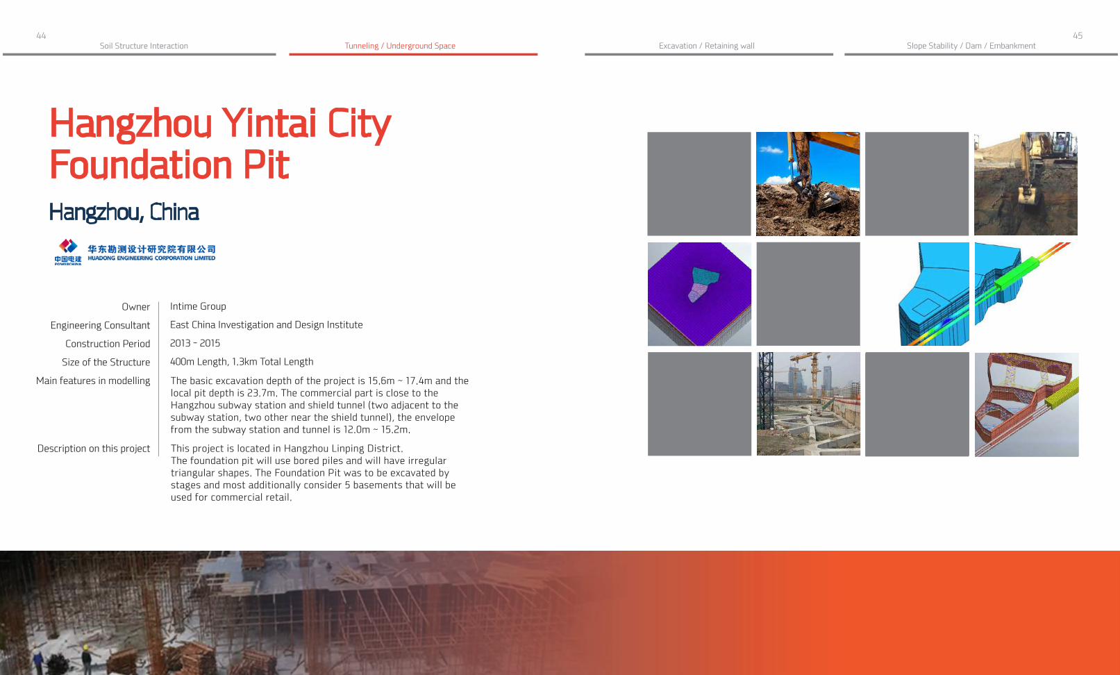
Hangzhou Yintai City Foundation Pit Hangzhou, China
Owner
Engineering Consultant
Construction Period
Size of the Structure
Main features in modelling
Intime Group
East China Investigation and Design Institute
2013 - 2015
400m Length, 1.3km Total Length
The basic excavation depth of the project is 15.6m ~ 17.4m and the local pit depth is 23.7m. The commercial part is close to the Hangzhou subway station and shield tunnel (two adjacent to the subway station, two other near the shield tunnel), the envelope from the subway station and tunnel is 12.0m ~ 15.2m.
This project is located in Hangzhou Linping District. The foundation pit will use bored piles and will have irregular triangular shapes. The Foundation Pit was to be excavated by stages and most additionally consider 5 basements that will be used for commercial retail.
Slope Stability / Dam / Embankment
Description on this project

46 47Tunneling / Underground Space Excavation / Retaining wallSoil Structure Interaction Slope Stability / Dam / Embankment
Busan Subway Line 3 Tunnel - Zone 321
Busan, Korea
Design for constructionPerforming construction stage analysis to check the settlement while checking the initial support capacity for the fan plant structure.
OverviewTwo types of analysis were performed based on different 3D model files. The full underground structure was modeled to monitor the initial support capacity including rock bolts and shotcrete, at structural level. A construction sequences analysis of the fan plant was ran to obtain the general stability and settlements of the soil layers, at geotechnical level.
48 49Soil Structure Interaction Slope Stability / Dam / Embankment
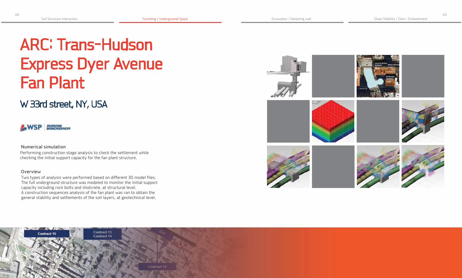
ARC: Trans-Hudson Express Dyer Avenue Fan PlantW 33rd street, NY, USA
Numerical simulationPerforming construction stage analysis to check the settlement while checking the initial support capacity for the fan plant structure.
OverviewTwo types of analysis were performed based on different 3D model files. The full underground structure was modeled to monitor the initial support capacity including rock bolts and shotcrete, at structural level. A construction sequences analysis of the fan plant was ran to obtain the general stability and settlements of the soil layers, at geotechnical level.
Tunneling / Underground Space Excavation / Retaining wall

50 51Tunneling / Underground Space Excavation / Retaining wallSoil Structure Interaction
Tunnel ExcavationConnectionWhen examining existing structures, it is necessary to perform verification calculations taking into account actual operating conditions. Because of the intersection of the several underground structures, 3D FE analysis was required to estimate the overall interaction behavior.
Slope Stability / Dam / Embankment
Tunnel ExcavationConnection
When designing a new tunnel, it was necessary to assess the effect of the new construction on existing structures. As a result of the 3D FEM analysis,
it was possible to estimate the overall deformation along the most critical area.

52 53Tunneling / Underground Space Excavation / Retaining wallSoil Structure Interaction
Tunnel ExcavationConnectionThis project was to assess the stress-strain state of underground structures under the real operating conditions. The main concern was the tunnel located near the additional excavations for galleries and ventilation trunk.
Slope Stability / Dam / Embankment
Tunnel ExcavationConnection
The main objective of this project was to maintain the operational availability of the reservoir in connection with the construction of new tunnels.
For the reinforcement of the existing structure, bored piles with a diameter of 800mm and a length of 26m were installed under the structure.

54 55
EXCAVATION / RETAINING WALL
Analysis methods
Construction Stage Analysis
Fully-Coupled Stress-Seepage Analysis
Slope Stability Analysis
* Dynamic Analysis (Seismic Capacity)
Design considerations
Support system / Type of wall
Internal / external stability
Deformations during and after construction
Effect on adjacent structures

56 57Tunneling / Underground Space Excavation / Retaining wallSoil Structure Interaction
Skyway Monte Bianco - Funivia del Monte BiancoCourmayeur, Italy
Owner
General Contractor
Engineering Consultant
Architecture
Design
Construction Period
Project Type
Main features in modelling
Description on this project
Funivie Monte Bianco AG
Cogeis
Holzner & Bertagnolli Engineering
Studio Progetti
Dimensione Ingenierie
2010 - 2015
Aerial Lift
- Rock excavation stability on top of the mountain- Tensile variations of the existing tie rods cableway
The cable car in Aosta Valley, at the entrance to the Mont Blanc tunnel, leads from Courmayeur to 1,200m above sea level. The new cable car valley station is being built near an existing station, as well as a restaurant which must remain operational. A 3D FEM analysis was required to analyze the interaction of the new construction and current adjacent structures.
Slope Stability / Dam / Embankment

58 59Tunneling / Underground Space Excavation / Retaining wallSoil Structure Interaction
Odeon Tower Mona
co, Monaco
Owner
General Contractor
Engineering Consultant
Architecture
Construction Period
Project Type
Size of the Structure
Main features in modelling
Description on this project
Group Marzocco
Vinci Construction France
Coyne et Bellier
Alexandre Giraldi
2010 - 2015
Office Building
170m Height (49-Story)
- Assessment of ground movements especially at adjacent building foundations- Deep excavation in a sloping site and retaining system (especially arching effects on the uphill side)
The Odeon Tower is a double - skyscraper in the Principality of Monaco. It was the first high-rise in the city to be built since the 1980s. But high-rise constructions had been abandoned due to aesthetic concerns and criticism of over-development. 3D model of excavation and construction sequence was necessary to ensure adjacent school buildings will not be affected.
Slope Stability / Dam / Embankment

60 61Tunneling / Underground Space Excavation / Retaining wallSoil Structure Interaction
Hefei Metro Line 4Anhui, China
Slope Stability / Dam / Embankment
Owner
Engineering Consultant
Construction Period
Project Type
Size of the Structure
Main features in modelling
Description on this project
Hefei Urban Mass Transit Co., Ltd
Traffic Planning and Design Institute of Anhui Province
Completed in 2015
Subway Tunnel
68.2×17.2m the Foundation pit
The impact of shield construction on buildings
Hefei subway tunnel would be excavated next to a high-rise building with a 21m long pipe pile foundation. The building’s foundation runs parallel to the tunnel excavation for an extended segment of the new project. Theorefore, 3D FEM model was required to verify differential settlement on the existing structure.

62 63Soil Structure Interaction
Canton Tower Foundation DitchGuangzhou, China
Slope Stability / Dam / Embankment
Owner
General Contractor
Architecture
Engineering Consultant
Construction Period
Project Type
Size of the Structure
Main features in modelling
Description on this project
Guangzhou New TV Tower
Guangzhou Municipal Construction Group JV / Shanghai Construction
Guangzhou Design Institute
Arup
2005 - 2010
Observation & Television Transmission Tower
600m Height
Foundation pit excavation stability analysis
Canton Tower is constructed as a composite tube-in-tube design, featuring a reinforced concrete core containing all the tower’s services and vertical transportation which set inside an outer structure made up of a steel lattice. The two structural components then support series of smaller structures suspended within the tower at different elevations. The slenderness of the tower’s design makes it especially vulnerable to sway in the wind, and requires the inclusion of a tuned mass damper system. A 3D FEM model with dynamic loads and construction stages was used to verify the foundation’s stability during construction and operational use.
Tunneling / Underground Space Excavation / Retaining wall

64 65Tunneling / Underground Space Excavation / Retaining wall
Engineering Consultant
Size of the Structure
Main features in modelling
Description on this project
Soil Structure Interaction
Hangzhou a Block of Commercial - Financial Space Foundation Pit Works
Hangzhou, China
Hangzhou Survey and Design Institute
20m Height, 26,000m2Area
A 3D FEM analysis of the impact of excavation on the subway station and tunnel was used to ensure the design meets the requirements of metro deformation control standards while considering the safe use of existing facilities.
The excavation area is about 26,000m2 and a depth of 20.2m. The pile is constructed by using the bored piles. The excavation pit is surrounded by a building complex and the Metro Line 2 Qingchun Road Station. Analysis was required to verify the excavation will not affect adjacent structures.
Slope Stability / Dam / Embankment

66 67Tunneling / Underground Space Excavation / Retaining wallSoil Structure Interaction Slope Stability / Dam / Embankment
Subway Impact Assessment - Minam Complex Construction
Busan, Korea
Design for ConstructionInvestigation of existing subway structure subjected to excavation for new building construction.
OverviewSafety investigation for 2-Arch tunnels and 1-Arch type tunnel where a large-scale excavation for a new building foundation takes place with temporary shoring within close proximity.
68 69Tunneling / Underground Space Excavation / Retaining wallSoil Structure Interaction
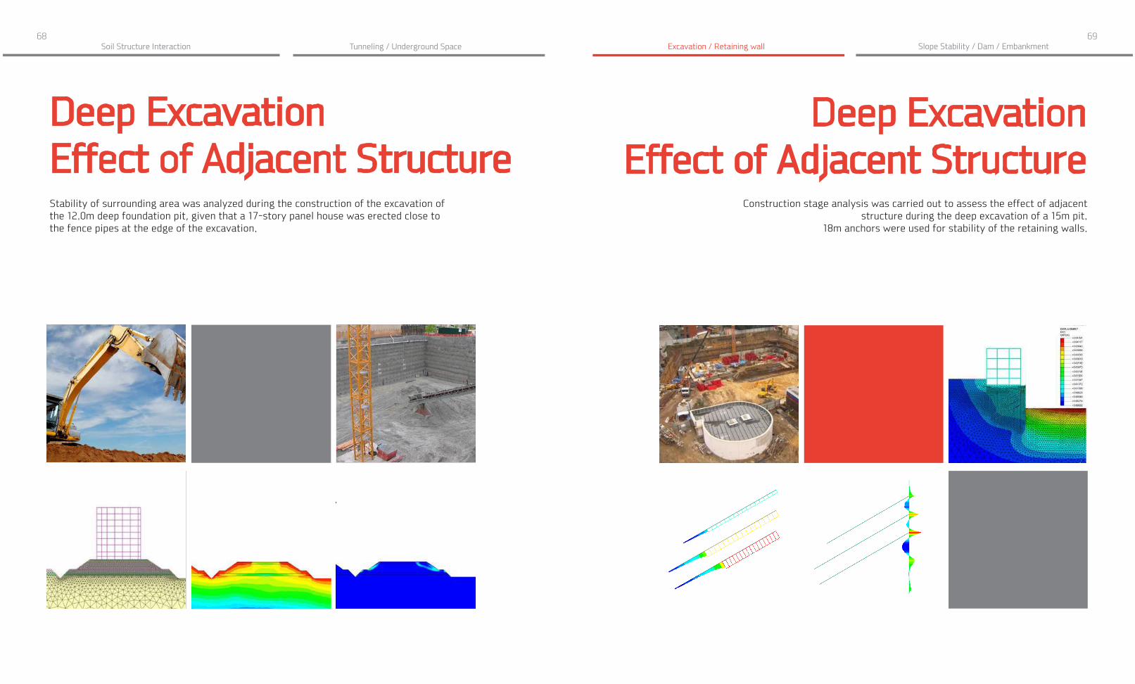
Deep Excavation Effect of Adjacent StructureStability of surrounding area was analyzed during the construction of the excavation of the 12.0m deep foundation pit, given that a 17-story panel house was erected close to the fence pipes at the edge of the excavation.
Slope Stability / Dam / Embankment
Deep Excavation Effect of Adjacent Structure
Construction stage analysis was carried out to assess the effect of adjacent structure during the deep excavation of a 15m pit.
18m anchors were used for stability of the retaining walls.

70 71Tunneling / Underground Space Excavation / Retaining wallSoil Structure Interaction
Deep Excavation Pile FoundationA construction stage analysis was used to design the complex foundation, which is a combination of piled raft and retaining walls with a thickness of 1m and depth of 36m. There is a three-story underground structure of rectangular shape with dimensions in the plan of 170.5m x 58m. Vertical bearing structures are steel columns, which are supported by piles with a diameter of 2m and a depth of 51m.
Slope Stability / Dam / Embankment
Deep Excavation Effect of Adjacent Structure
A 3D FEM analysis was used to calculate the impact on surrounding buildings and a network of pipelines during the excavation and construction of multi-functional
complex with deep pile foundation.

72 73Tunneling / Underground Space Excavation / Retaining wallSoil Structure Interaction
Deep Excavation Effect of Adjacent Structure3D soil layers and all the structural members such as pylons, slabs and foundations were modeled completely, in order to asses the effect on the existing building due to the new construction.
Slope Stability / Dam / Embankment
Deep Excavation Effect of Adjacent Structure
The purpose of this project is to estimate the stability of the underground structures. Verification calculations of the underground structure of the foundation pit were carried
out with 4 different geotechnical software including a 3D simulation in GTS NX.

74 75Tunneling / Underground Space Excavation / Retaining wallSoil Structure Interaction
Deep Excavation Effect of Adjacent StructureThe impact of the new excavation and the phased construction of a high-rise building on the existing buildings, structures was the most critical issue for this project. Non-uniform soil layers including ground surface were taken into account for more realistic simulation.
Slope Stability / Dam / Embankment
Deep Excavation Effect of Adjacent Structure
A 3D FEM model was necessary to assess the effects of tunneling and construction of a pit for the Southern Station Complex on existing airport facilities.

76 77
2
SLOPE STABILITY / DAM / EMBANKMENT
Analysis methods
Slope Stability Analysis (SRM / SAM)
Seepage Analysis
Fully-Coupled Stress-Seepage Analysis
* Dynamic Analysis (Seismic Capacity)
Design considerations
Min. Factor of safety / Reinforcement methods
Global stability / Potential failure
Dam stability considering water level fluctuations
Seepage face / Velocity / Hydraulic gradient

78 79Tunneling / Underground Space Excavation / Retaining wallSoil Structure Interaction
Grand Ethiopian Renaissance - Dam Project Nilo River, Ethiopia
Slope Stability / Dam / Embankment
Owner
Engineering Consultant
Construction Period
Project Type
Size of the Structure
Main features in modelling
Description on this project
Ethiopian Electric Power
Studio Masciotta
2011 - 2017
Dam
173m Height
- Stability analysis under static and dynamic loading conditions
The Grand Ethiopian Renaissance Dam is a gravity dam on the Blue Nile River in Ethiopia. The dam will be the largest hydroelectric power plant in Africa when completed, as well as the 7th largest in the world. The storage reservoir has a surface area of 1561 km² at level of 640 m, i.e. 146 m behind the dam which holds a large volume of water equal to 79 billion m³.
- Nonlinear static analysis with phased construction

80 81Tunneling / Underground Space Excavation / Retaining wallSoil Structure Interaction
Buhang Dam Gimcheon, Korea
Owner
Engineering Consultant
Construction Period
Project Type
Size of the Structure
Main features in modelling
Description on this project
Korea Water Resources Corporation
GS E&C
2006 - 2014
Concrete/Flood - Control Dam
472m Length, 75m Height
- Evaluate the deformation and member force of cut - off wall due to water pressure- Deformation and stress distribution with constitutive models
Buhang Dam is located in Gimcheon City, Gyeongsangbukdo, South Korea. After typhoon Rusa passed, a dam was deemed to be necessary to prevent flood damage. It is expected to contribute to the development of local communities through the supply of river maintenance water for dams and minimization of flood damage in the Gamcheon coastal area around Gimcheon City. It will also supply drinking water and agricultural water in Gwangcheon and Gumi.
Slope Stability / Dam / Embankment

82 83Soil Structure Interaction
Slope StabilityReinforcement2D and 3D slope stability analysis has been performed in order to strengthen the southern slope, made of clay and loose sand, against the potential failure under heavy rainfall.
Slope Stability / Dam / Embankment
Slope StabilityEmbankment
3D slope stability analysis with stone pile reinforcement was used during the filling of an embankment to prevent collapse.
Tunneling / Underground Space Excavation / Retaining wall

84 85Tunneling / Underground Space Excavation / Retaining wallSoil Structure Interaction
Dam StabilityEffect of Water Level Fluctuations 2D seepage-slope coupled analysis was carried out to assess the effect of water level drawdown (rapid or slow) and the rainfall. Additionally, the horizontal seismic effect also taken into account for the overall stability.
Slope Stability / Dam / Embankment
Slope StabilityPotential Failure Surface
2D FEM analysis was required to determine the stress-strain state, and the strength and stability of the slope since it was considered to be potentially dangerous given the
complex geological structure and hydro-geological conditions.

86 87Tunneling / Underground Space Excavation / Retaining wallSoil Structure Interaction Slope Stability / Dam / Embankment
Slope StabilityStaged Excavation
Dam StabilitySoil Structure Interaction

88 89
Past and Present Projects and the Potential Future with MIDAS.

Midasoft1 646 852 9294
http://northamerica.midasuser.com


