IEEE MMIC seminar Bergen 2006 10 06 H Zirath 1. The principle of resistive mixers Frequency translation by using resistive mixing i(t)=g(t) v(t) The current through the (timedependent) resistor is the product of the conductance and the applied voltage We are interested in the frequencies generated by this multiplication in the time domain g(t) can be represented by a Fourier series with the fundamental frequency ω p v(t) + - g( t ) = G n n =− ∞ ∞ ∑ ⋅ exp( j ⋅ n ⋅ ω p ⋅ t ) See Steven Maas Nonlinear Microwave Circuits pp.114-137 g(t)
Transcript
IEEE MMIC seminar Bergen 2006 10 06 H Zirath
1. The principle of resistive mixers
Frequency translation by using resistive mixing
i(t)=g(t) v(t)
The current through the (timedependent) resistor is the product of the conductance and the applied voltageWe are interested in the frequencies generated by this multiplication in the time domain
g(t) can be represented by a Fourier serieswith the fundamental frequency ωp
v(t)
+
-
g( t) = Gnn =− ∞
∞
∑ ⋅ exp( j ⋅n ⋅ ω p ⋅ t)See Steven MaasNonlinear Microwave Circuitspp.114-137
g(t)
IEEE MMIC seminar Bergen 2006 10 06 H Zirath
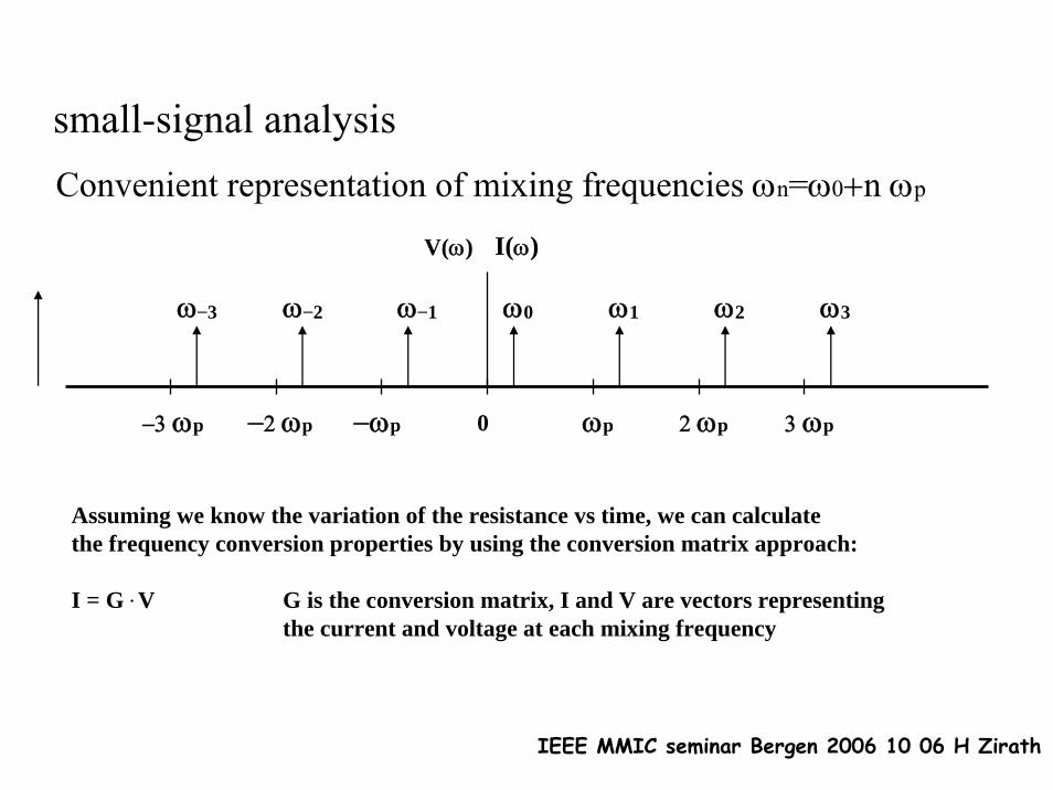
small-signal analysisConvenient representation of mixing frequencies ωn=ω0+n ωp
0 ωp−ωp 2 ωp 3 ωp−2 ωp−3 ωp
ω0 ω1 ω2 ω3ω−1ω−2ω−3
Assuming we know the variation of the resistance vs time, we can calculatethe frequency conversion properties by using the conversion matrix approach:
I = G . V G is the conversion matrix, I and V are vectors representingthe current and voltage at each mixing frequency
V(ω) I(ω)
IEEE MMIC seminar Bergen 2006 10 06 H Zirath
I−N*
I−N+1*
I−N+2*
I−1*
I0
I1
IN−1
IN
⎡
⎣
⎢ ⎢ ⎢ ⎢ ⎢ ⎢ ⎢ ⎢ ⎢ ⎢ ⎢ ⎢ ⎢ ⎢ ⎢
⎤
⎦
⎥ ⎥ ⎥ ⎥ ⎥ ⎥ ⎥ ⎥ ⎥ ⎥ ⎥ ⎥ ⎥ ⎥ ⎥
=
G0 G−1 G−2 G−2N
G1 G0 G−1 G−2N+1
G2 G−1 G0 G−2N+2
G0
G0
G0
GN−1 GN−2 GN−3 G1 G0 G−1 G−N−1
GN GN−1 GN−2 G3 G2 G1 G0 G−1 G−2 G−3 G−N
GN+1 GN GN−1 G1 G0 G−1 G−N+1
G0
G0
G0
G0
G0
G2N G2N−1 G2N−2 G0
⎡
⎣
⎢ ⎢ ⎢ ⎢ ⎢ ⎢ ⎢ ⎢ ⎢ ⎢ ⎢ ⎢ ⎢ ⎢ ⎢
⎤
⎦
⎥ ⎥ ⎥ ⎥ ⎥ ⎥ ⎥ ⎥ ⎥ ⎥ ⎥ ⎥ ⎥ ⎥ ⎥
•
V−N*
V−N+1*
V−1*
V0
V1
VN−1
VN
⎡
⎣
⎢ ⎢ ⎢ ⎢ ⎢ ⎢ ⎢ ⎢ ⎢ ⎢ ⎢ ⎢ ⎢ ⎢ ⎢
⎤
⎦
⎥ ⎥ ⎥ ⎥ ⎥ ⎥ ⎥ ⎥ ⎥ ⎥ ⎥ ⎥ ⎥ ⎥ ⎥
we get:
IEEE MMIC seminar Bergen 2006 10 06 H Zirath
We want to know how the mixer properties depend on the characteristic of the conductance waveform and the embedding impedance
The conversion matrix can be extended by reactive components, forming a conversion matrix in admittance form. This is a valuable tool when analysing the properties of diode and transistor mixers. We have now transfered the nonlinear problem to the frequency domain and can use linear equations for solving the problem.
port1
port2
port3
port4
port5
port6
Y
ω0
ω1
ω-1
ω-2
ω2
ω3
etc
IEEE MMIC seminar Bergen 2006 10 06 H Zirath
non-square waveform, harmonic response
To illustrate the harmonic response, lets look at Gn as a function of the duty-cycle for a simple case, an ideally switched conductance
g(t) = Gnn =− ∞
∞
∑ ⋅ exp( j ⋅n ⋅ ω p ⋅ t)Gct0
T
Gc
0
We obtain: G0 = t0T
⋅GC , G1 = GC
π⋅ sin(π ⋅ t0
T)
G2 =GC
2π⋅sin(2π ⋅
t0T
) , G3 =GC
3π⋅ sin(3π ⋅
t0
T)
G4 =GC
4π⋅sin(4π⋅
t0
T) , G5 =
GC
5π⋅sin(5π⋅
t0T
)
Gn =1T
g(t )⋅ exp(−j ⋅n ⋅ω ⋅ t)−
T2
T2
∫
IEEE MMIC seminar Bergen 2006 10 06 H Zirath
The most used device for the resistive mixer is the Schottky diode, it can be used up to THz-frequencies.
The FET-based resistive mixer is an interesting alternative if1. generation of intermodulation products is critical2. FET/HEMT based MMIC designs are considered3. LO and RF are close together and large bandwidth is required
+
-
VD
ID = I0 ⋅eq⋅Vd /ηkT
rB =∂ID
∂VD
⎛
⎝ ⎜ ⎞
⎠ ⎟
−1
→ηkTqID
or rB =k ⋅e−q⋅Vd / ηkT
IDS = K(VGS)⋅ 1+λ ⋅VDS( )⋅ tanh(α⋅VDS)
the diode and FET/HEMT as a variable resistance
IEEE MMIC seminar Bergen 2006 10 06 H Zirath
0
0.01
0.02
0.03
0 0.5 1 1.5 2
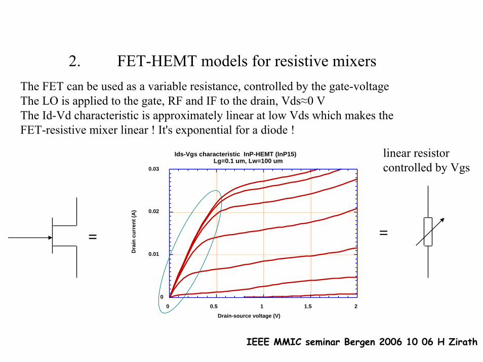
Ids-Vgs characteristic InP-HEMT (InP15)Lg=0.1 um, Lw=100 um
Dra
in c
urre
nt (A
)
Drain-source voltage (V)
= =
The FET can be used as a variable resistance, controlled by the gate-voltageThe LO is applied to the gate, RF and IF to the drain, Vds≈0 VThe Id-Vd characteristic is approximately linear at low Vds which makes the FET-resistive mixer linear ! It's exponential for a diode !
linear resistorcontrolled by Vgs
2. FET-HEMT models for resistive mixers
IEEE MMIC seminar Bergen 2006 10 06 H Zirath
The Rds-Vgs slope is important for the determination of the LO-power requirement of the mixer
10 -8
10 -7
10 -6
10 -5
0.0001
0.001
0.01
-1.5 -1 -0.5 0 0.5 1 1.5
Ids vs Vgs at small Vds -50 mV
Ids (
A)
Vgs (V)
10
100
1000
10 4
10 5
10 6
-1 -0.5 0 0.5 1
Rds vs Vgs: InP15, Lw=100 um
Rds
(ohm
)
Vgs (V)
IEEE MMIC seminar Bergen 2006 10 06 H Zirath
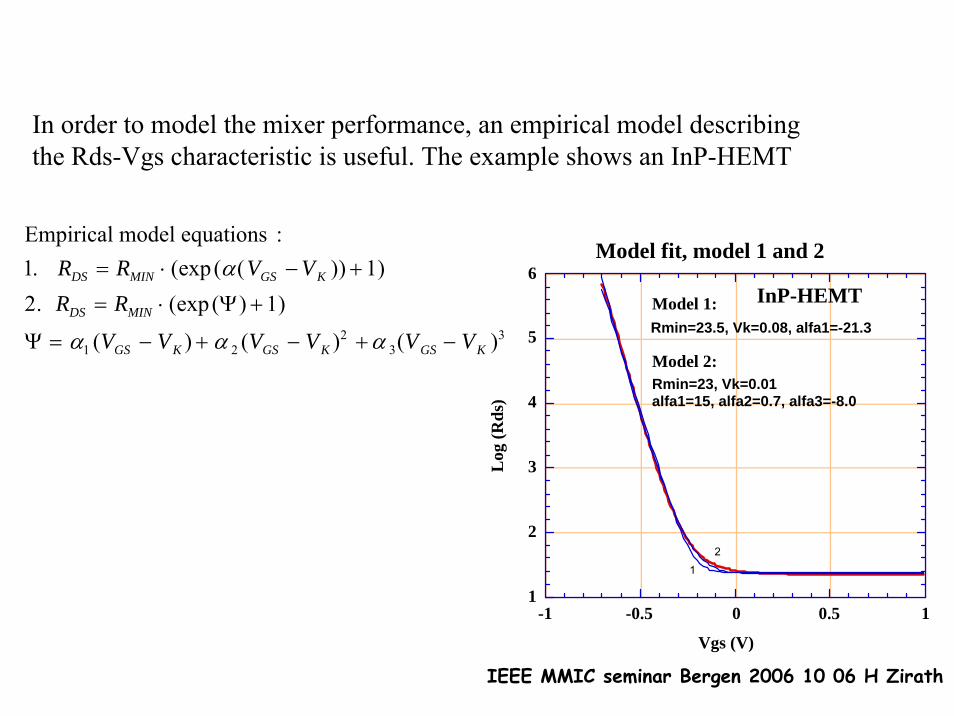
In order to model the mixer performance, an empirical model describingthe Rds-Vgs characteristic is useful. The example shows an InP-HEMT
For 'small signal' simulations this equivalent circuit is usedrch and cgs,cgd are the most important bias-dependent parameters(Rds is now split into Rd+rch+Rs)
The equivalent circuit including capacitances
IEEE MMIC seminar Bergen 2006 10 06 H Zirath
3. The single-ended mixer (1)
LOmatchLO
RF
IF
Vg
Performance of different FET-HEMT based resistive mixers
This mixer is simple since no hybrids/filtersare needed for the LO-injection->high BW. The LO-RF-isolation is of the order 10-20 dBdepending mainly on the transistor design.The total conversion loss is less than 6 dBThe required LO-power is typically 0-10 dBmdepending mainly on the transistor type
Q-band-mixer (50 GHz) with WG-input:
IEEE MMIC seminar Bergen 2006 10 06 H Zirath
The single-ended mixer (2) comparison between different HEMTs
100-10-20-30-405
10
15
20
25
30
PM3
InP9
PM2
LO=39 GHz; RF=43 GHz
LO-power (dBm)
Con
vers
ion
loss
(dB
)
4846444240386
8
10
12
14
PM3
In9
PM2Plo=9 dBm
Freq. (GHz)
Con
vers
ion
loss
(dB
)
Three different HEMTs where compared in a 40 GHz MIC-mixer:
1. Single delta doped AlGaAs-InGaAs-GaAs HEMT. (PM2)2. Double delta doped AlGaAs-InGaAs-GaAs HEMT. (PM3)3. Single delta doped AlInAs-GaInAs-InP HEMT. (InP9)
IEEE MMIC seminar Bergen 2006 10 06 H Zirath
MMIC mixer
Resistive FET-mixers have been realized up to F-band, this monolithic mixer is based on an AlInAs-GaInAs-InP HEMT-technology (including vias) and made at CTH.The conversion loss is ≈ 9 dB at 4 dBm LO-power. Frequency is 115 GHz.
LO
IF
RF
Vg-bias
Local oscillator power (dBm)
Lc (dB)
010
20
10
0-10
MEASMEAS
SIMSIM
IEEE MMIC seminar Bergen 2006 10 06 H Zirath
PowersplitLO
RF
Vg
0 deg
180 deg
IF
IF
Balanced mixers
In applications where high LO-RF isolation is required, a balanced mixer can be used.The LO is splitted with 180 deg phase difference between the two ports. The residualLO at the drains will be minimized.An LO-RF isolation of better than 35 dB and a total conversion loss of better than 10 dBwas obtained for this balanced 50-60 GHz upconverting mixer with 5 dBm LO-power.
Block diagram:55 GHz Alumina MIC-mixer
Lo Rf-out
IF-in
IF-in
IEEE MMIC seminar Bergen 2006 10 06 H Zirath
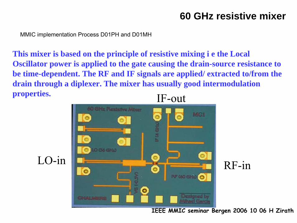
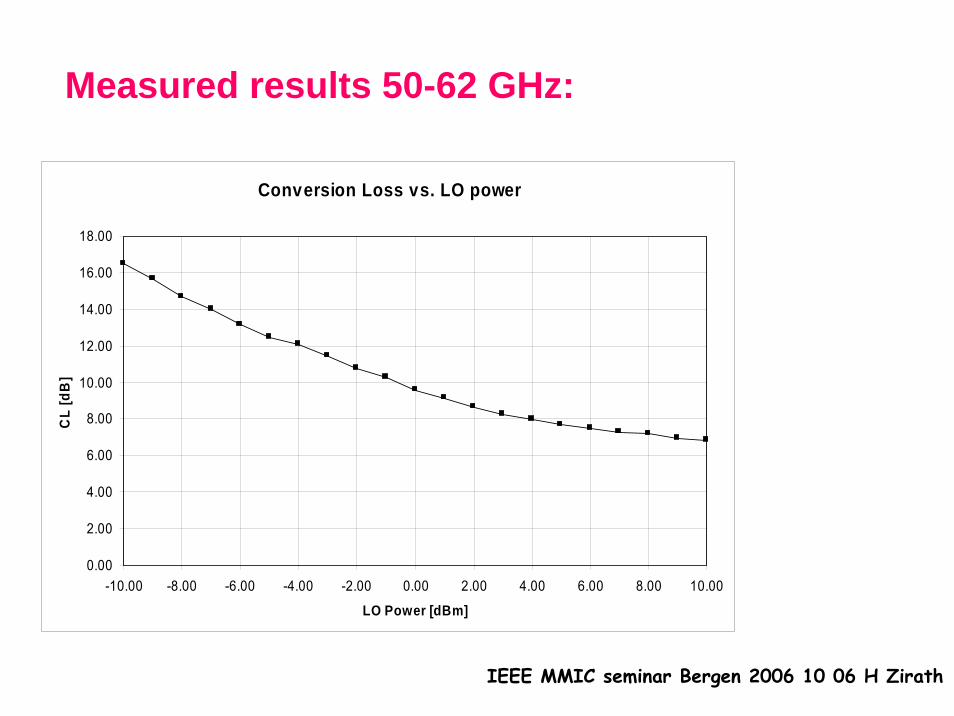
60 GHz resistive mixer
This mixer is based on the principle of resistive mixing i e the Local Oscillator power is applied to the gate causing the drain-source resistance to be time-dependent. The RF and IF signals are applied/ extracted to/from the drain through a diplexer. The mixer has usually good intermodulationproperties.
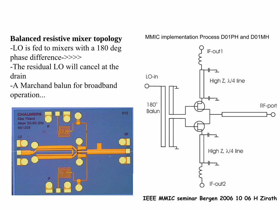
Balanced resistive mixer topology-LO is fed to mixers with a 180 deg phase difference->>>>-The residual LO will cancel at the drain-A Marchand balun for broadband operation...
MMIC implementation Process D01PH and D01MH
IEEE MMIC seminar Bergen 2006 10 06 H Zirath
Short form data:30-60 dB LO->RF isolation, IIP3 =19dBm at 8 dBm PLO5-8 dB NF (DSB), P-1 ≈ PLO+(2-4dB)
0
2
4
6
8
10
12
14
16
18
20
-4 -2 0 2 4 6 8
Plo (dBm)
IIP3
(dBm
)
pHEMTmHEMT
0,00
5,00
10,00
15,00
20,00
25,00
30 35 40 45 50
RF Frequency (GHz)
NF_
DSB
(dB)
-0.1 -0.3
-0.5 -0.7
-0.9
NFminIIP3
0
5
10
15
20
-5 0 5 10Lo-power (dBm)
LO-RF isolation
20
25
30
35
40
45
50
55
60
65
30 35 40 45 50
Frequency (GHz)
Isol
atio
n (d
B)
LO-RF isolation
No source biasNo source bias
IEEE MMIC seminar Bergen 2006 10 06 H Zirath
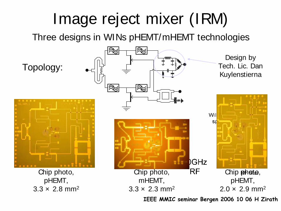
Image reject mixer (IRM)Three designs in WINs pHEMT/mHEMT technologies
Topology:
Chip photo, pHEMT,
3.3 × 2.8 mm2
Chip photo, mHEMT,
3.3 × 2.3 mm2
Chip photo, pHEMT,
2.0 × 2.9 mm2
Design by Tech. Lic. Dan Kuylenstierna
IEEE MMIC seminar Bergen 2006 10 06 H Zirath
Image reject mixer (IRM)
World record in image rejection ratio World record in image rejection ratio (IRR) (IRR) versus versus RF frequency. URF frequency. Ultra wideband IF characteristics!ltra wideband IF characteristics!
IRM1
IRM30
5
10
15
20
25
30
35
0 0,5 1 1,5 2 2,5 3 3,5 4 4,5 5 IF frequency (GHz)
Lc; I
RR
(dB
)
Lc - IRM1Lc - IRM3IRR - IRM1IRR - IRM3
0
5
10
15
20
25
30
35
40
0 10 20 30 40 50 60 70 80 90 100RF freq ( GHz)
IRR
(dB)
[ IRM1]
[12]
[ IRM3]
[13]
[14]
[15]
[16]
[17]
[18]
[19]
[20]
[21]
Comparison with IRMs published by others, (references
according to paper E)
Conversion loss and image rejection ratio versus IF frequency
IEEE MMIC seminar Bergen 2006 10 06 H Zirath
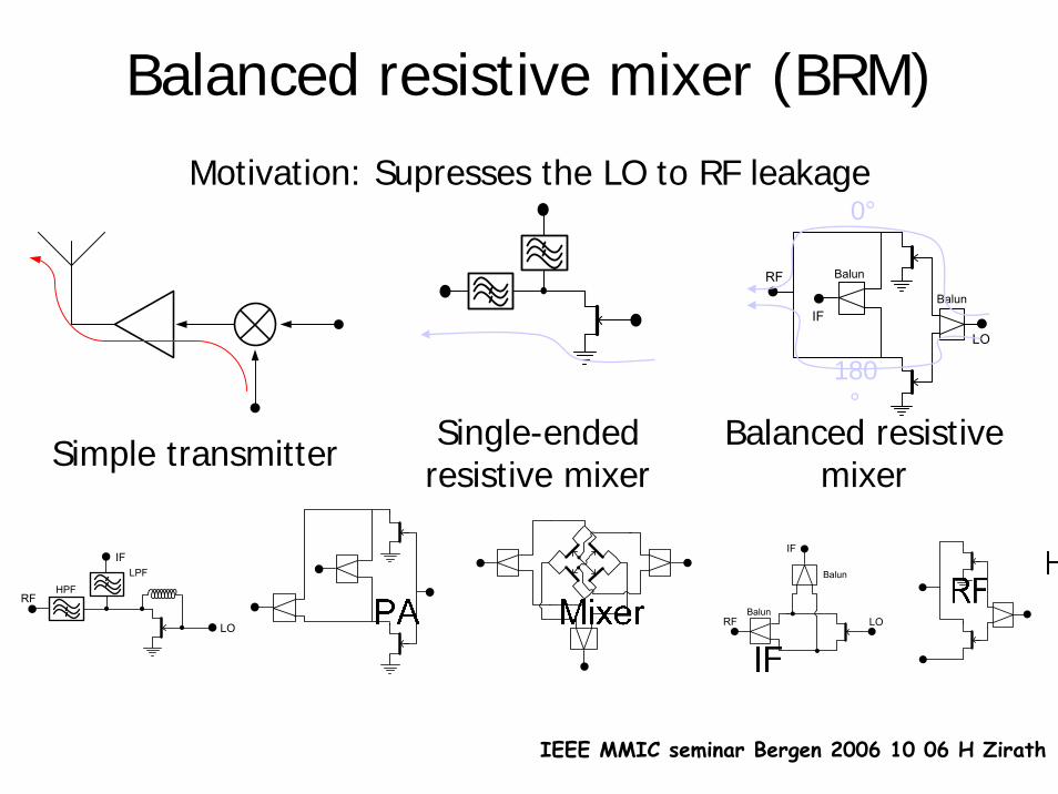
Balanced resistive mixer (BRM)Motivation: Supresses the LO to RF leakage
RF
LO
BalunIF
Balun
RF
IFLPF
HPF
LO
Single-ended resistive mixer
RFBalun
IF
Balun
LO
Balanced resistive mixer Simple transmitter
0°
180°
IEEE MMIC seminar Bergen 2006 10 06 H Zirath
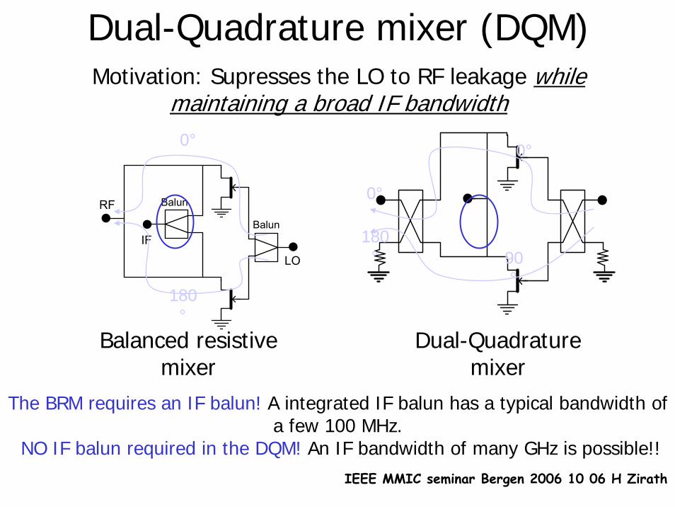
Dual-Quadrature mixer (DQM)Motivation: Supresses the LO to RF leakage while
maintaining a broad IF bandwidth
Dual-Quadrature mixer
RF
LO
BalunIF
Balun
Balanced resistive mixer
0°
180°
0°
0°
90°
180°
The BRM requires an IF balun! A integrated IF balun has a typical bandwidth of a few 100 MHz.
NO IF balun required in the DQM! An IF bandwidth of many GHz is possible!!
IEEE MMIC seminar Bergen 2006 10 06 H Zirath
Dual-Quadrature mixer (DQM)WIN pHEMT technology
Chip photo, 3 × 1.5 mm2Topology
The DQM topology was for the first time recognized for its The DQM topology was for the first time recognized for its potential to achieve high LO to RF isolation potential to achieve high LO to RF isolation (> 20 dB) (> 20 dB) while while
maintaining a very broad IF bandwidthmaintaining a very broad IF bandwidth (11.5 GHz!)(11.5 GHz!)
IEEE MMIC seminar Bergen 2006 10 06 H Zirath
Why 60 GHz?
• 59 – 63 GHz license free band• 4 GHz (!) of bandwidth High speed wireless communication• High oxygen absorption Less interference Shorter cell re-use
60 GHz activities at Chalmers – the beginning1997 – 2001 : The “60 GHz WLAN” project (CTH, Ericsson, KTH, and FOI within CHACH)
2x2x4x4x
BasebandInput
IF-Amp Mixer Power Amp
TX Filter
IF-Amp Mixer LNA RX Filter
Multipliers Buffer
PowerSplitter
BasebandOutput
PowerCombiner
orSwitch
AntennaVCO
IEEE MMIC seminar Bergen 2006 10 06 H Zirath
Three main design goals were formulated:• As high level of integration as possible• As general design in terms of modulation format as possible• As high data rate as possible Transmission of broadband signals,
i.e. high data rate!!
Design group at Chalmers: Sten E. Gunnarsson, Camilla KSten E. Gunnarsson, Camilla Käärnfelt, Herbert Zirath,rnfelt, Herbert Zirath,Rumen Kozhuharov, and Dan KuylenstiernaRumen Kozhuharov, and Dan Kuylenstierna
60 GHz activities at Chalmers –continuation
2003 – 2005 : The “60 GHz broadband wireless communication systems (BRAWO)” project (CTH and Ericsson within CHACH)
Integrate all subIntegrate all sub--blocks in a 60 GHz frontblocks in a 60 GHz front--end into singleend into single--chip chip transmitter (TX) and receiver (RX) MMICstransmitter (TX) and receiver (RX) MMICs
Paper B Paper B and Cand C
IEEE MMIC seminar Bergen 2006 10 06 H Zirath
Receiver (RX) and Transmitter (TX) chip designed at Chalmers – topology and chip photo
Image RejectMixer 2.5 GHz
IF
7.1875 GHz LO
X4 X2
LNA
FBA
3 stageAmp.
Buff.
60 GHzRF
RX chip
X8
Chip photo, pHEMT,5.7 x 5 mm2
Two versions in WINs pHEMT/mHEMT technologies
Bal. Res.Mixer 2.5 GHz
IF
7.1875 GHz LO
X4 X2
PA
FBA
3 stageAmp.
Buff.
60 GHzRF
TX chip
X8
Topology- RX
Topology- TX
Chip photo, pHEMT,5 x 3.5 mm2
IEEE MMIC seminar Bergen 2006 10 06 H Zirath
Conversion Gain and Image Rejection Ratio versus IF Frequency for the RX chip, fLO=7.1875 × 8 =57.5 GHz.
Receiver (RX) and Transmitter (TX) chip designed at Chalmers – measured results
Maximum output power versus IF frequency for theTX chip, fLO=7.1875 GHz × 8 =57.5 GHz.
”First-shot” in pHEMT. WWorldorld record in terms of integration of a 60 GHz frontrecord in terms of integration of a 60 GHz front--endend
Redesigned and more compact chips in mHEMT
SmallerHigher gain Half of the DC power consumptionHalf of the DC power consumption