59
Lesson 1 Types of fasteners: Pins and keys Version 2 ME, IIT Kharagpur www.jntuworld.com www.jntuworld.com www.jwjobs.net

Lesson 1
Types of fasteners: Pins
and keys
Version 2 ME, IIT Kharagpur
www.jntuworld.com
www.jntuworld.com
www.jwjobs.net

Instructional Objectives
At the end of this lesson, the students should have the knowledge of
• Fasteners and their types: permanent and detachable fasteners.
• Different types of pin joints.
• Different types of keys and their applications.
4.1.1 Introduction: Types of fasteners A machine or a structure is made of a large number of parts and they need be
joined suitably for the machine to operate satisfactorily. Parts are joined by
fasteners and they are conveniently classified as permanent or detachable
fasteners. They are often sub- divided under the main headings as follows:
Permanent fasteners: Riveted joints
Welded joints
Detachable joints: Threaded fasteners – screws, bolts and nuts, studs.
Cotter joints
Knuckle joints
Keys and Pin joints Starting with the simple pin and key joints all the main fasteners will be discussed
here.
4.1.2 Pin Joints These are primarily used to prevent sliding of one part on the other, such as, to
secure wheels, gears, pulleys, levers etc. on shafts. Pins and keys are primarily
used to transmit torque and to prevent axial motion. In engineering practice the
following types of pins are generally used.
Version 2 ME, IIT Kharagpur
www.jntuworld.com
www.jntuworld.com
www.jwjobs.net

(a) Round pins (b) Taper pins (c) Dowel pins (d) Split pins
Round and taper pins are simple cylindrical pins with or without a taper and they
offer effective means of fastening pulleys, gears or levers to a shaft. It may be
fitted such that half the pin lies in the hub and the other half in the shaft as shown
in figure-4.1.2.1 (b). The pin may be driven through the hub and the shaft as in
figure- 4.1.2.1 (c) or as in figure- 4.1.2.1 (d). These joints give positive grip and
the pins are subjected to a shear load. For example, for the shaft in the assembly
shown in figure- 4.1.2.1 (c), the pin is under double shear and we have
2 1D2 d . T4 2π⎛ ⎞τ =⎜ ⎟
⎝ ⎠
where d is the diameter of the pin at hub-shaft interface, τ is the yield strength in
shear of the pin material and T is the torque transmitted.
D1 d1 d2
Pin
Hub
Shaft
L
d1
d2
(d)(a) (c)(b) 4.1.2.1F- Different types of pin joints
A taper pin is preferred over the straight cylindrical pins because they can be
driven easily and it is easy to ream a taper hole.
Dowel pins These are used to keep two machine parts in proper alignment. Figure- 4.1.2.2
demonstrates the use of dowel pins. Small cylindrical pins are normally used for
this purpose.
Version 2 ME, IIT Kharagpur
www.jntuworld.com
www.jntuworld.com
www.jwjobs.net

4.1.2.2F- Some uses of Dowel pins (Ref.[6]).
(a) (b)
Split pins These are sometimes called cotter pins also and they are made of annealed iron
or brass wire. They are generally of semi-circular cross section and are used to
prevent nuts from loosening as shown in figure- 4.1.2.3. These are extensively
used in automobile industry.
Split pin
4.1.2.3F- Typical use of a split pin (Ref.[6]).
4.1.3 Keys Steel keys are widely used in securing machine parts such as gears and pulleys.
There is a large variety of machine keys and they may be classified under four
broad headings:
Sunk keys, flat keys, saddle keys and pins or round keys
Version 2 ME, IIT Kharagpur
www.jntuworld.com
www.jntuworld.com
www.jwjobs.net
Sunk keys may be further classified into the following categories:
(a) Rectangular sunk keys
(b) Gib head sunk keys
(c) Feather keys
(d) Woodruff keys
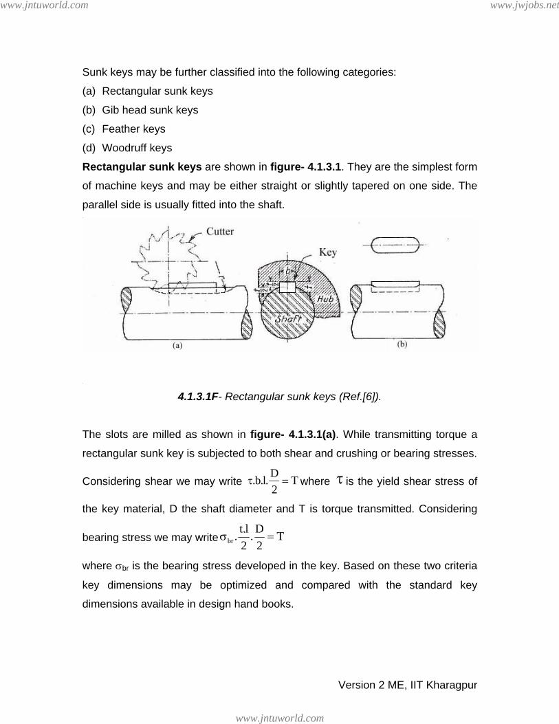
Rectangular sunk keys are shown in figure- 4.1.3.1. They are the simplest form
of machine keys and may be either straight or slightly tapered on one side. The
parallel side is usually fitted into the shaft.
4.1.3.1F- Rectangular sunk keys (Ref.[6]).
The slots are milled as shown in figure- 4.1.3.1(a). While transmitting torque a
rectangular sunk key is subjected to both shear and crushing or bearing stresses.
Considering shear we may write D.b.l. T2
τ = where τ is the yield shear stress of
the key material, D the shaft diameter and T is torque transmitted. Considering
bearing stress we may write brt.l D. . T2 2
σ =
where σbr is the bearing stress developed in the key. Based on these two criteria
key dimensions may be optimized and compared with the standard key
dimensions available in design hand books.
Version 2 ME, IIT Kharagpur
www.jntuworld.com
www.jntuworld.com
www.jwjobs.net

The gib head keys are ordinary sunk keys tapered on top with a raised head on
one side so that its removal is easy. This is shown in figure- 4.1.3.2
4.1.3.2F- Gib head key (Ref.[6]).
Some feather key arrangements are shown in figure- 4.1.3.3. A feather key is
used when one component slides over another. The key may be fastened either
to the hub or the shaft and the keyway usually has a sliding fit.
4.1.3.3F- Some feather key arrangements (Ref.[6]).
A woodruff key is a form of sunk key where the key shape is that of a truncated
disc, as shown in figure- 4.1.3.4. It is usually used for shafts less than about 60
mm diameter and the keyway is cut in the shaft using a milling cutter, as shown
in the figure- 4.1.3.4. It is widely used in machine tools and automobiles due to
the extra advantage derived from the extra depth.
Version 2 ME, IIT Kharagpur
www.jntuworld.com
www.jntuworld.com
www.jwjobs.net

4.1.3.4F- Woodruff key (Ref.[6]).
Lewis keys, shown in figure- 4.1.3.5, are expensive but offer excellent service.
They may be used as a single or double key. When they are used as a single key
the positioning depends on the direction of rotation of the shaft. For heavy load
two keys can be used as shown in figure- 4.1.3.5 (b).
db6dt
12
=
=
4.1.3.5F- Lewis keys (Ref.[6]).
A flat key, as shown in figure- 4.1.3.6 is used for light load because they depend
entirely on friction for the grip. The sides of these keys are parallel but the top is
Version 2 ME, IIT Kharagpur
www.jntuworld.com
www.jntuworld.com
www.jwjobs.net

slightly tapered for a tight fit. Theses keys have about half the thickness of sunk
keys.
4.1.3.6F- Flat key (Ref.[6]). 4.1.3.7F- Saddle key (Ref.[6]).
A saddle key, shown in figure- 4.1.3.7, is very similar to a flat key except that
the bottom side is concave to fit the shaft surface. These keys also have friction
grip and therefore cannot be used for heavy loads. A simple pin can be used as a
key to transmit large torques. Very little stress concentration occurs in the shaft in
these cases. This is shown in figure- 4.1.2.1 (b).
4.1.4 Problems with Answers
Q.1: Two 30 mm diameter shafts are connected by pins in an arrangement
shown in figure-4.1.4.1. Find the pin diameter if the allowable shear stress
of the pins is 100 MPa and the shaft transmits 5 kW at 150 rpm.
Driven shaftDriving shaft
T
D= 30 mm
Coupling bush
4.1.4.1F
Version 2 ME, IIT Kharagpur
www.jntuworld.com
www.jntuworld.com
www.jwjobs.net
A.1:
The torque transmitted T= Power/ 2 N60π⎛
⎜⎝ ⎠
⎞⎟ . Substituting power = 5x10³
Watts and N=150 rpm we have T = 318.3 Nm. The torque is transmitted
from the driving shaft to the coupling bush via a pin. The torque path is
then reversed and it is transmitted from the coupling bush to the driven
shaft via another pin. Therefore both the pins transmit a torque of 318.3
Nm under double shear. We may then write 2y
DT 2. .d . .4 2π
= τ . Substituting
D=0.03 m, τy = 100 MPa and T= 318.3 MPa we have d=11.6 mm ≈ 12
mm.
Q.2: A heat treated steel shaft of tensile yield strength of 350 MPa has a
diameter of 50 mm. The shaft rotates at 1000 rpm and transmits 100 kW
through a gear. Select an appropriate key for the gear.
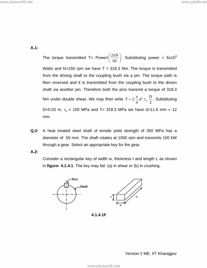
A.2: Consider a rectangular key of width w, thickness t and length L as shown
in figure- 4.1.4.1. The key may fail (a) in shear or (b) in crushing.
Key
Shaft
L
w
t
4.1.4.1F
Version 2 ME, IIT Kharagpur
www.jntuworld.com
www.jntuworld.com
www.jwjobs.net

Shear failure: The failure criterion is ydT .w.L.2
= τ
(1)
where torque transmitted is T= Power/ 2 N60π⎛ ⎞
⎜ ⎟⎝ ⎠
(2) N being in rpm, w, L and d are the width, length and diameter of the shaft
respectively and τy is the yield stress in shear of the key material. Taking
τy to be half of the tensile yield stress and substituting the values in
equations (1) and (2) we have wL = 2.19 x 10⁻⁴ m2.
Crushing failure: ct.L dT . .2 2
= σ
(3)
Taking σc to be the same as σy and substituting values in equation (3) we
have
tL= 2.19 x 10⁻⁴ m2. Some standard key dimensions are reproduced in
table- 4.1.4.1:
Shaft
Diameter
(mm)
30-38 38-44 44-50 50-58 58-65 65-75 75-85
Key width, w
(mm) 10 12 14 16 18 20 22
Key depth, t
(mm) 8 9 9 10 11 12 14
Key length, L
(mm) 22-110 28-140 36-160 45-180 50-200 56-220 63-250
4.1.4.1T Based on the standard we may choose w=16 mm. This gives L = 13.6
mm. We may then choose the safe key dimensions as
Version 2 ME, IIT Kharagpur
www.jntuworld.com
www.jntuworld.com
www.jwjobs.net

w = 16 mm L = 45 mm t = 10 mm.
4.1.5 Summary of this Lesson In this lesson firstly the types detachable of fasteners are discussed. Then
types and applications of pin and key joints are discussed with suitable
illustrations. A brief overview of key design is also included.
Version 2 ME, IIT Kharagpur
www.jntuworld.com
www.jntuworld.com
www.jwjobs.net
Version 2 ME, IIT Kharagpur
Module 4
Fasteners
www.jntuworld.com
www.jntuworld.com
www.jwjobs.net

Version 2 ME, IIT Kharagpur
Lesson 2
Cotter and knuckle
joint
www.jntuworld.com
www.jntuworld.com
www.jwjobs.net

Version 2 ME, IIT Kharagpur
Instructional Objectives
At the end of this lesson, the students should have the knowledge of
• A typical cotter joint, its components and working principle.
• Detailed design procedure of a cotter joint.
• A typical knuckle joint, its components and working principle.
• Detailed design procedure of a knuckle joint.
4.2.1 Cotter joint A cotter is a flat wedge-shaped piece of steel as shown in figure-4.2.1.1. This is
used to connect rigidly two rods which transmit motion in the axial direction,
without rotation. These joints may be subjected to tensile or compressive forces
along the axes of the rods.
Examples of cotter joint connections are: connection of piston rod to the
crosshead of a steam engine, valve rod and its stem etc.
4.2.1.1F- A typical cotter with a taper on one side only (Ref.[6]).
A typical cotter joint is as shown in figure-4.2.1.2. One of the rods has a socket
end into which the other rod is inserted and the cotter is driven into a slot, made
in both the socket and the rod. The cotter tapers in width (usually 1:24) on one
www.jntuworld.com
www.jntuworld.com
www.jwjobs.net

Version 2 ME, IIT Kharagpur
side only and when this is driven in, the rod is forced into the socket. However, if
the taper is provided on both the edges it must be less than the sum of the
friction angles for both the edges to make it self locking i.e 1 2 1 2α +α < φ + φ where
1α , 2α are the angles of taper on the rod edge and socket edge of the cotter
respectively and φ1, φ2 are the corresponding angles of friction. This also means
that if taper is given on one side only then 1 2α < φ + φ for self locking. Clearances
between the cotter and slots in the rod end and socket allows the driven cotter to
draw together the two parts of the joint until the socket end comes in contact with
the cotter on the rod end.
b d d2l1 d1
l
d3
d4
t1
4.2.1.2F- Cross-sectional views of a typical cotter joint (Ref.[6]).
4.2.1.3F- An isometric view of a typical cotter joint (Ref.[6]).
www.jntuworld.com
www.jntuworld.com
www.jwjobs.net

Version 2 ME, IIT Kharagpur
4.2.2 Design of a cotter joint If the allowable stresses in tension, compression and shear for the socket, rod
and cotter be tσ , cσ and τ respectively, assuming that they are all made of the
same material, we may write the following failure criteria:
1. Tension failure of rod at diameter d
2td P
4π
σ =
4.2.2.1F- Tension failure of the rod (Ref.[6]).
2. Tension failure of rod across slot
2
1 1 td d t P4π⎛ ⎞− σ =⎜ ⎟
⎝ ⎠
4.2.2.2F- Tension failure of rod across slot (Ref.[6]).
t
www.jntuworld.com
www.jntuworld.com
www.jwjobs.net

Version 2 ME, IIT Kharagpur
3. Tensile failure of socket across slot
2 22 1 2 1 t(d d ) (d d )t P
4π⎛ ⎞− − − σ =⎜ ⎟
⎝ ⎠
4.2.2.3F- Tensile failure of socket across slot (Ref.[6]).
4. Shear failure of cotter
2bt Pτ =
4.2.2.4F- Shear failure of cotter (Ref.[6]).
5. Shear failure of rod end
1 12 d Pτ =l
4.2.2.5F- Shear failure of rod end (Ref.[6]).
d2t
www.jntuworld.com
www.jntuworld.com
www.jwjobs.net

Version 2 ME, IIT Kharagpur
6. Shear failure of socket end
( )3 12 d d P− τ =l
4.2.2.6F- Shear failure of socket end (Ref.[6]).
7. Crushing failure of rod or cotter
1 cd t Pσ =
4.2.2.7F- Crushing failure of rod or cotter (Ref.[6]).
8. Crushing failure of socket or rod
( )3 1 cd d t P− σ =
4.2.2.8F- Crushing failure of socket or rod (Ref.[6]).
d
www.jntuworld.com
www.jntuworld.com
www.jwjobs.net

Version 2 ME, IIT Kharagpur
9. Crushing failure of collar
2 24 1 c(d d ) P
4π⎛ ⎞− σ =⎜ ⎟
⎝ ⎠
4.2.2.9F- Crushing failure of collar (Ref.[6]).
10. Shear failure of collar
1 1d t Pπ τ =
4.2.2.10F- Shear failure of collar (Ref.[6]).
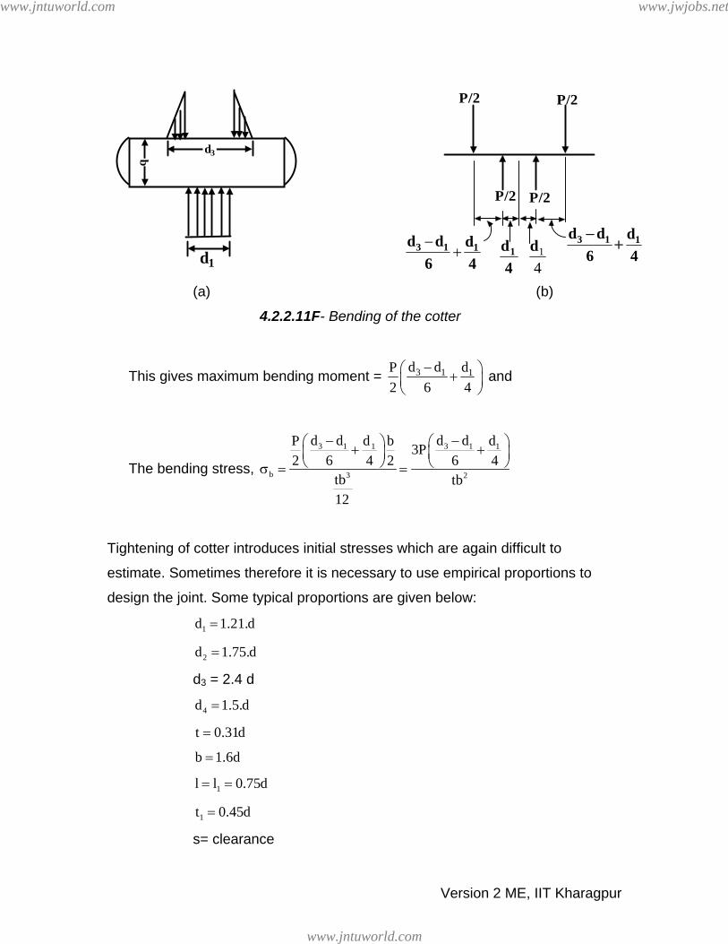
Cotters may bend when driven into position. When this occurs, the bending
moment cannot be correctly estimated since the pressure distribution is not
known. However, if we assume a triangular pressure distribution over the rod, as
shown in figure-4.2.2.11 (a), we may approximate the loading as shown in figure-
4.2.2.11 (b)
www.jntuworld.com
www.jntuworld.com
www.jwjobs.net
Version 2 ME, IIT Kharagpur
(a) (b)
4.2.2.11F- Bending of the cotter
This gives maximum bending moment = 3 1 1d d dP2 6 4
−⎛ ⎞+⎜ ⎟⎝ ⎠
and
The bending stress,
3 1 3 11 1
b 3 2
d d d dd dP b 3P2 6 4 2 6 4
tb tb12
− −⎛ ⎞ ⎛ ⎞+ +⎜ ⎟ ⎜ ⎟⎝ ⎠ ⎝ ⎠σ = =
Tightening of cotter introduces initial stresses which are again difficult to
estimate. Sometimes therefore it is necessary to use empirical proportions to
design the joint. Some typical proportions are given below:
1d 1.21.d=
2d 1.75.d=
d3 = 2.4 d
4d 1.5.d=
t 0.31d=
b 1.6d=
1l l 0.75d= =
1t 0.45d=
s= clearance
d3b
d1
P/2 P/2
P/2 P/2
−+3 1 1d d d
6 4
3 1 1d d d6 4−
+1d4
1
4d
www.jntuworld.com
www.jntuworld.com
www.jwjobs.net

Version 2 ME, IIT Kharagpur
A design based on empirical relation may be checked using the formulae based
on failure mechanisms.
4.2.3 Knuckle Joint A knuckle joint (as shown in figure- 4.2.3.1) is used to connect two rods under
tensile load. This joint permits angular misalignment of the rods and may take
compressive load if it is guided.
4.2.3.1F- A typical knuckle joint
These joints are used for different types of connections e.g. tie rods, tension links
in bridge structure. In this, one of the rods has an eye at the rod end and the
other one is forked with eyes at both the legs. A pin (knuckle pin) is inserted
through the rod-end eye and fork-end eyes and is secured by a collar and a split
pin.
Normally, empirical relations are available to find different dimensions of the joint
and they are safe from design point of view. The proportions are given in the
figure-4.2.3.1.
1.2d 1.2d
1.2d d dP P
1.2d
0.6d
d2
d3
d3
d1
tt 1
t 2t 1
t 20.
25d
Split pin
0.8d
www.jntuworld.com
www.jntuworld.com
www.jwjobs.net

Version 2 ME, IIT Kharagpur
d = diameter of rod
1d d= t 1.25d=
2d 2d= 1t 0.75d=
3d 1.5.d= 2t 0.5d=
Mean diameter of the split pin = 0.25 d
However, failures analysis may be carried out for checking. The analyses are
shown below assuming the same materials for the rods and pins and the yield
stresses in tension, compression and shear are given by σt, σc and τ.
1. Failure of rod in tension:
2td P
4π
σ =
2. Failure of knuckle pin in double shear:
212 d P
4π
τ =
3. Failure of knuckle pin in bending (if the pin is loose in the fork)
Assuming a triangular pressure distribution on the pin, the loading on the pin is
shown in figure- 4.2.3.2.
Equating the maximum bending stress to tensile or compressive yield stress we
have
1
t 31
t t16P3 4d
⎛ ⎞+⎜ ⎟⎝ ⎠σ =π
www.jntuworld.com
www.jntuworld.com
www.jwjobs.net

Version 2 ME, IIT Kharagpur
4.2.3.2F- Bending of a knuckle pin
4. Failure of rod eye in shear:
( )2 1d d t P− τ =
5. Failure of rod eye in crushing:
1 cd t Pσ =
6. Failure of rod eye in tension:
( )2 1 td d t P− σ =
7. Failure of forked end in shear:
( )2 1 12 d d t P− τ =
8. Failure of forked end in tension:
( )2 1 1 t2 d d t P− σ =
9. Failure of forked end in crushing:
2d1t1σc = P
The design may be carried out using the empirical proportions and then the
analytical relations may be used as checks.
d1
P/2 P/2
P/2 P/21t t3 4+ 1t t
3 4+
t1 t1t/2 t/2
www.jntuworld.com
www.jntuworld.com
www.jwjobs.net

Version 2 ME, IIT Kharagpur
For example using the 2nd equation we have 21
2Pd
τ =π
. We may now put value of
d1 from empirical relation and then find F.S. = yττ
which should be more than
one.
4.2.4 Problems with Answers
Q.1: Design a typical cotter joint to transmit a load of 50 kN in tension or
compression. Consider that the rod, socket and cotter are all made of a
material with the following allowable stresses:
Allowable tensile stress σy = 150 MPa
Allowable crushing stress σc = 110 MPa
Allowable shear stress τy = 110 MPa.
A.1: Refer to figure- 4.2.1.2 and 4.2.2.1
Axial load 2yP d
4π
= σ . On substitution this gives d=20 mm. In general
standard shaft size in mm are
6 mm to 22 mm diameter 2 mm in increment
25 mm to 60 mm diameter 5 mm in increment
60 mm to 110 mm diameter 10 mm in increment
110 mm to 140 mm diameter 15 mm in increment
140 mm to 160 mm diameter 20 mm in increment
500 mm to 600 mm diameter 30 mm in increment
We therefore choose a suitable rod size to be 25 mm.
Refer to figure-4.2.2.2
www.jntuworld.com
www.jntuworld.com
www.jwjobs.net
Version 2 ME, IIT Kharagpur
For tension failure across slot 21 yd d t P
4π⎛ ⎞− σ =⎜ ⎟
⎝ ⎠. This gives 4
1d t 1.58x10−=
m2.From empirical relations we may take t=0.4d i.e. 10 mm and this gives
d1= 15.8 mm. Maintaining the proportion let d1= 1.2 d = 30 mm.
Refer to figure-4.2.2.3
The tensile failure of socket across slot ( )2 22 1 2 1 yd d d d t P
4⎧ ⎫π⎛ ⎞− − − σ =⎨ ⎬⎜ ⎟⎝ ⎠⎩ ⎭
This gives d2 = 37 mm. Let d2 = 40 mm
Refer to figure-4.2.2.4
For shear failure of cotter 2btτ = P. On substitution this gives b = 22.72
mm.
Let b = 25 mm.
Refer to figure-4.2.2.5
For shear failure of rod end 2l1d1τ = P and this gives l1 = 7.57 mm. Let l1 =
10 mm.
Refer to figure-4.2.2.6
For shear failure of socket end 2l(d2-d1)τ = P. This gives l= 22.72 mm. Let
l=25 mm
Refer to figure-4.2.2.8
For crushing failure of socket or rod (d3-d1)tσc = P. This gives d3 = 75.5
mm. Let d3 = 77 mm.
Refer to figure-4.2.2.9
For crushing failure of collar ( )2 24 1 cd d P
4π
− σ = . On substitution this gives
d4= 38.4 mm. Let d4= 40 mm.
www.jntuworld.com
www.jntuworld.com
www.jwjobs.net
Version 2 ME, IIT Kharagpur
Refer to figure-4.2.2.10
For shear failure of collar πd1t1τ = P which gives t1= 4.8 mm. Let t1 = 5
mm.
Therefore the final chosen values of dimensions are
d= 25 mm; d1= 30 mm; d2 = 40 mm; d3 = 77 mm; d4 = 40 mm; t= 10 mm;
t1= 5 mm; l= 25 mm; l1= 10 mm; b= 27 mm.
Q.2: Two mild steel rods are connected by a knuckle joint to transmit an axial
force of 100 kN. Design the joint completely assuming the working
stresses for both the pin and rod materials to be 100 MPa in tension, 65
MPa in shear and 150 MPa in crushing.
A.2: Refer to figure- 4.2.3.1
For failure of rod in tension, 2yP d
4π
= σ . On substituting P=100 kN,
σy = 100 MPa we have d= 35.6 mm. Let us choose the rod diameter d =
40 mm which is the next standard size.
We may now use the empirical relations to find the necessary dimensions
and then check the failure criteria.
d1= 40 mm t= 50 mm
d2 = 80 mm t1= 30 mm;
d3 = 60 mm t2= 20 mm;
split pin diameter = 0.25 d1 = 10 mm
To check the failure modes:
1. Failure of knuckle pin in shear: 21 yP 2. d
4π⎛ ⎞ = τ⎜ ⎟
⎝ ⎠ which gives τy = 39.8
MPa. This is less than the yield shear stress.
2. For failure of knuckle pin in bending:
1
y 31
t t16P3 4d
⎛ ⎞+⎜ ⎟⎝ ⎠σ =π
. On substitution
this gives σy = 179 MPa which is more than the allowable tensile yield
www.jntuworld.com
www.jntuworld.com
www.jwjobs.net

Version 2 ME, IIT Kharagpur
stress of 100 MPa. We therefore increase the knuckle pin diameter to
55 mm which gives σy = 69 MPa that is well within the tensile yield
stress.
3. For failure of rod eye in shear: (d2-d1)tτ = P. On substitution d1 = 55mm
τ= 80 MPa which exceeds the yield shear stress of 65 MPa. So d2
should be at least 85.8 mm. Let d2 be 90 mm.
4. For failure of rod eye in crushing: d1tσc = P which gives σc = 36.36
MPa that is well within the crushing strength of 150 MPa.
5. Failure of rod eye in tension: (d2-d1)tσt = P. Tensile stress developed at
the rod eye is then σt = 57.14 MPa which is safe.
6. Failure of forked end in shear: 2(d2-d1)t1τ = P. Thus shear stress
developed in the forked end is τ = 47.61 MPa which is safe.
7. Failure of forked end in tension: 2(d2-d1)t1σy = P. Tensile strength
developed in the forked end is then σy= 47.61 MPa which is safe.
8. Failure of forked end in crushing: 2d1t1σc = P which gives the crushing
stress developed in the forked end as σc = 42 MPa. This is well within
the crushing strength of 150 MPa.
Therefore the final chosen values of dimensions are:
d1= 55 mm t= 50 mm
d2 = 90 mm t1= 30 mm; and d = 40 mm
d3 = 60 mm t2= 20 mm;
4.2.5 Summary of this Lesson In this lesson two well known joints viz. cotter and knuckle joints used in
machinery are discussed. Their constructional detail and working principle
have been described. Then the detailed design procedures of both these
joints are given with suitable illustrations. Finally two examples, one on
cotter joint and the other on cotter joint have been solved.
www.jntuworld.com
www.jntuworld.com
www.jwjobs.net

Module 4
Fasteners Version 2 ME, IIT Kharagpur
www.jntuworld.com
www.jntuworld.com
www.jwjobs.net

Lesson 3
Threaded Fasteners
Version 2 ME, IIT Kharagpur
www.jntuworld.com
www.jntuworld.com
www.jwjobs.net

Instructional Objectives
At the end of this lesson, the students should have the knowledge of
• Different types of bolts, screws and studs.
• Some details of tapping and set screws.
• Thread forms in details.
4.3.1 Bolts, screws and studs are the most common types of
threaded fasteners. They are used in both permanent or
removable joints.
Bolts: They are basically threaded fasteners normally used with nuts.
Screws: They engage either with a preformed or a self made internal threads.
Studs: They are externally threaded headless fasteners. One end usually meets
a tapped component and the other with a standard nut.
There are different forms of bolt and screw heads for a different usage. These
include bolt heads of square, hexagonal or eye shape and screw heads of
hexagonal, Fillister, button head, counter sunk or Phillips type. These are shown
in figures-4.3.1.1 and 4.3.1.2.
4.3.1.1F- Types of screw heads (Ref.[6]).
Version 2 ME, IIT Kharagpur
www.jntuworld.com
www.jntuworld.com
www.jwjobs.net

4.3.1.2F- Types of bolt heads (Ref.[6])..
Tapping screws These are one piece fasteners which cut or form a mating thread when driven
into a preformed hole. These allow rapid installation since nuts are not used.
There are two types of tapping screws. They are known as thread forming
which displaces or forms the adjacent materials and thread cutting which have
cutting edges and chip cavities which create a mating thread.
Set Screws These are semi permanent fasteners which hold collars, pulleys, gears etc on a
shaft. Different heads and point styles are available. Some of them are shown in
figure-4.3.1.3.
Version 2 ME, IIT Kharagpur
www.jntuworld.com
www.jntuworld.com
www.jwjobs.net

4.3.1.3F- Different types of set screws (Ref.[6])..
4.3.2 Thread forms Basically when a helical groove is cut or generated over a cylindrical or conical
section, threads are formed. When a point moves parallel to the axis of a rotating
cylinder or cone held between centers, a helix is generated. Screw threads
formed in this way have two functions to perform in general:
(a) To transmit power - Square. ACME, Buttress, Knuckle types of thread
forms are useful for this purpose.
(b) To secure one member to another- V-threads are most useful for this
purpose.
Some standard forms are shown in figure-4.3.2.1 V-threads are generally used for securing because they do not shake loose due
to the wedging action provided by the thread. Square threads give higher
efficiency due to a low friction. This is demonstrated in figure- 4.3.2.2.
Version 2 ME, IIT Kharagpur
www.jntuworld.com
www.jntuworld.com
www.jwjobs.net

4.3.2.1F- Different types of thread forms (Ref.[6]).
Version 2 ME, IIT Kharagpur
www.jntuworld.com
www.jntuworld.com
www.jwjobs.net

Fα F
cosα
V-thread
F
Square thread
4.3.2.2F- Loading on square and V threads.
4.3.3 Summary of this Lesson
In this lesson firstly different types of bolts, set screws and studs are
discussed. Some details of set and tapping screws are also discussed.
Constructional details of thread forms and their applications have also
been included.
Version 2 ME, IIT Kharagpur
www.jntuworld.com
www.jntuworld.com
www.jwjobs.net

Module 4
Fasteners Version 2 ME, IIT Kharagpur
www.jntuworld.com
www.jntuworld.com
www.jwjobs.net

Lesson 4
Design of bolted joints
Version 2 ME, IIT Kharagpur
www.jntuworld.com
www.jntuworld.com
www.jwjobs.net
Instructional Objectives
At the end of this lesson, the students should have the knowledge of
• Different types of stresses developed in screw fasteners due to initial
tightening and external load.
• Combined effect of initial tightening and external load on a bolted joint.
• Leak proof joints and condition for joint separation.
4.4.1 Stresses in screw fastenings It is necessary to determine the stresses in screw fastening due to both static and
dynamic loading in order to determine their dimensions. In order to design for
static loading both initial tightening and external loadings need be known.
4.4.1.1 Initial tightening load When a nut is tightened over a screw following stresses are induced:
(a) Tensile stresses due to stretching of the bolt
(b) Torsional shear stress due to frictional resistance at the threads.
(c) Shear stress across threads
(d) Compressive or crushing stress on the threads
(e) Bending stress if the surfaces under the bolt head or nut are not perfectly
normal to the bolt axis.
(a) Tensile stress
Since none of the above mentioned stresses can be accurately determined bolts
are usually designed on the basis of direct tensile stress with a large factor of
safety. The initial tension in the bolt may be estimated by an empirical relation
P 1=284 d kN, where the nominal bolt diameter d is given in mm. The relation is
used for making the joint leak proof. If leak proofing is not required half of the
above estimated load may be used. However, since initial stress is inversely
proportional to square of the diameter 2
284d
d4
⎛ ⎞⎜ ⎟σ =⎜ π⎜ ⎟⎝ ⎠
⎟ , bolts of smaller diameter such
Version 2 ME, IIT Kharagpur
www.jntuworld.com
www.jntuworld.com
www.jwjobs.net

as M16 or M8 may fail during initial tightening. In such cases torque wrenches
must be used to apply known load.
The torque in wrenches is given by T= C P 1d where, C is a constant depending
on coefficient of friction at the mating surfaces, P is tightening up load and d is
the bolt diameter.
1
(b) Torsional shear stress
This is given by 3c
16T
dτ =
π where T is the torque and d the core diameter. We
may relate torque T to the tightening load P 1 in a power screw configuration
(figure-4.4.1.1.1 ) and taking collar friction into account we may write
c
T= P 1 m m
m
d l d sec2 d Lsec⎛ ⎞+μπ α⎜ ⎟π −μ α⎝ ⎠
+2dP cmc1μ
where d and d are the mean thread diameter and mean collar diameter
respectively, and are the coefficients of thread and collar friction
respectively and
m cm
μ cμ
α is the semi thread angle. If we consider that
d = cm( )
2d5.1d mm +
then we may write T= C P 1 d m where C is a constant for a given arrangement.
As discussed earlier similar equations are used to find the torque in a wrench.
4.4.1.1.1F- A typical power screw configuration
Version 2 ME, IIT Kharagpur
www.jntuworld.com
www.jntuworld.com
www.jwjobs.net

(c) Shear stress across the threads
This is given by c
3Pd bn
τ =π
where d is the core diameter and b is the base width
of the thread and n is the number of threads sharing the load
c
(d) Crushing stress on threads
This is given by ( )
c2 2
0 c
P
d d4
σ =π
− n where and d are the outside and core
diameters as shown in figure- 4.4.1.1.1
0d c
(e) Bending stress If the underside of the bolt and the bolted part are not parallel as shown in figure-4.4.1.1.2, the bolt may be subjected to bending and the bending stress may be
given by
BxE2L
σ = where x is the difference in height between the extreme corners of the
nut or bolt head, L is length of the bolt head shank and E is the young’s modulus.
4.4.1.1.2F- Development of bending stress in a bolt
4.4.1.2 Stresses due to an external load If we consider an eye hook bolt as shown in figure- 4.4.1.2.1 where the complete
machinery weight is supported by threaded portion of the bolt, then the bolt is
Version 2 ME, IIT Kharagpur
www.jntuworld.com
www.jntuworld.com
www.jwjobs.net

subjected to an axial load and the weakest section will be at the root of the
thread. On this basis we may write
P =22
cd4π
tσ
where for fine threads dc =0.88d and for coarse threads dc =0.84d, d being the
nominal diameter.
P2
4.4.1.2.1F- An eye hook bolt
Bolts are occasionally subjected to shear loads also, for example bolts in a flange
coupling as shown in figure- 4.4.1.2.2. It should be remembered in design that
shear stress on the bolts must be avoided as much as possible. However if this
cannot be avoided the shear plane should be on the shank of the bolt and not the
threaded portion. Bolt diameter in such cases may be found from the relation
T= 2cn d
4π τ
2PCD
where n is the number of bolts sharing the load, τ is the shear yield stress of the
bolt material. If the bolt is subjected to both tensile and shear loads, the shank
should be designed for shear and the threaded portion for tension. A diameter
slightly larger than that required for both the cases should be used and it should
be checked for failure using a suitable failure theory.
Version 2 ME, IIT Kharagpur
www.jntuworld.com
www.jntuworld.com
www.jwjobs.net

4.4.1.2.2F- A typical rigid flange coupling
4.4.1.3 Combined effect of initial tightening load and external load
When a bolt is subjected to both initial tightening and external loads i.e. when a
preloaded bolt is in tension or compression the resultant load on the bolt will
depend on the relative elastic yielding of the bolt and the connected members.
This situation may occur in steam engine cylinder cover joint for example. In this
case the bolts are initially tightened and then the steam pressure applies a tensile
load on the bolts. This is shown in figure-4.4.1.3.1 (a) and 4.4.1.3.1 (b).
P2
P2
P
2
2
P1
P1
P2
P
(a) (b) 4.4.1.3.1F- A bolted joint subjected to both initial tightening and external load
Version 2 ME, IIT Kharagpur
www.jntuworld.com
www.jntuworld.com
www.jwjobs.net

Initially due to preloading the bolt is elongated and the connected members are
compressed. When the external load P is applied, the bolt deformation increases
and the compression of the connected members decreases. Here P1 and P2 in
figure 4.4.1.3.1 (a) are the tensile loads on the bolt due to initial tightening and
external load respectively.
The increase in bolt deformation is given by bB
b
PK
δ = and decrease in member
compression is C
CC K
P=δ where, P b is the share of P2 in bolt, P C is the share of
P2 in members, K and K are the stiffnesses of bolt and members. If the parts are not separated then
b c
b cδ = δ and this gives
b
b
PK
= C
C
KP
Therefore, the total applied load P due to steam pressure is given by 2
P 2 = Pb + P C
This gives Pb= P K, where K = 2 ( )cb
b
KKK+
. Therefore the resultant load on bolt
is P +KP . Sometimes connected members may be more yielding than the bolt
and this may occurs when a soft gasket is placed between the surfaces. Under
these circumstances
1 2
K b >>K or cb
c
KK << 1 and this gives K≈ 1. Therefore the total load P = P 1 + P 2
Normally K has a value around 0.25 or 0.5 for a hard copper gasket with long
through bolts. On the other hand if K >>K , K approaches zero and the total
load P equals the initial tightening load. This may occur when there is no soft
gasket and metal to metal contact occurs. This is not desirable. Some typical
values of the constant K are given in table 4.4.1.3.1.
C b
Version 2 ME, IIT Kharagpur
www.jntuworld.com
www.jntuworld.com
www.jwjobs.net

Type of joint K
Metal to metal contact with through bolt
Hard copper gasket with long through
bolt
Soft copper gasket with through bolts
Soft packing with through bolts
Soft packing with studs
0-0.1
0.25-0.5
0.50-
0.75
0.75-
1.00
1.00
4.4.1.3.1T
4.4.2 Leak proof joint The above analysis is true as long as some initial compression exists. If the
external load is large enough the compression will be completely removed and
the whole external load will be carried by the bolt and the members may bodily
separate leading to leakage.
Therefore, the condition for leak proof joint is c
1
KP
> b
b
KP
. Substituting Pb=P K
and
2
c
b
K 1 KK K
−= the condition for a leak proof joint reduces to P1 >P (1-K). It is
therefore necessary to maintain a minimum level of initial tightening to avoid leakage.
2
4.4.3 Joint separation Clearly if the resultant load on a bolt vanishes a joint would separate and the
condition for joint separating may be written as P 1+KP =0 2
Therefore if P 1 >KP and P 1< A2 b tybσ , there will be no joint separation. Here A
and are the bolt contact area and tensile yield stress of the bolt material
respectively and condition ensures that there would be no yielding of the bolt due
to initial tightening load.
b
tybσ
Version 2 ME, IIT Kharagpur
www.jntuworld.com
www.jntuworld.com
www.jwjobs.net

The requirement for higher initial tension and higher gasket factor (K) for a better
joint may be explained by the simple diagram as in figure- 4.4.3.1.
45o
φ = tan-1(K)
P1Res
ulta
nt L
oad
P
P2 (External Load)
P= P2 line(i.e. when leakage starts)
More external load sustainedbefore leakage for higher K
Leakage starts here at P = P2*
P= P1+KP2
P2*
*
**
4.4.3.1F – Force diagram for joint separation
4.4.4 Problems with Answers
Q.1: 12 M20 x 2.5C bolts are used to hold the cylinder head of a reciprocating
air compressor in position. The air pressure is 7 MPa and the cylinder bore
diameter is 100 mm. A soft copper gasket with long bolts is used for
sealing. If the tensile yield stress of the bolt material is 500 MPa find the
suitability of the bolt for the purpose. Check if the joint is leak proof and
also if any joint separation may occur.
A.1: According to Indian Standard Thread designation M20 x 2.5C indicates a
metric bolt of nominal diameter 20 mm and a course pitch of 2.5 mm.
Some typical bolt dimensions are quoted in table-4.4.4.1 as recommended
by I.S. 4218-1978 (Part VI) :
Version 2 ME, IIT Kharagpur
www.jntuworld.com
www.jntuworld.com
www.jwjobs.net

Minor DiameterDesignation Pitch
(mm) Bolt
(mm)
Nut
(mm)
Stress
area
(mm2)
M2 0.40 1.509 1.567 207
M5 0.8 4.019 4.134 14.2
M10 1.25 8.466 8.647 61.6
M16 1.5 14.160 14.376 167
M20 1.5 18.160 18.376 272
M24 2 21.546 21.835 384
4.4.4.1T-
Based on this for M20 x 2.5C bolt the initial tightening load is given by
P1=284 d which is 56.8 kN.
External load on each bolt ( )2 6
2
x 0.1 x7x104P
12
π
= i.e. 4.58 kN.
From section 4.4.1.3 the constant K = 0.5-0.75. Taking an average value
of K=0.625 the total resultant load P is given by P=56.8+0.625x4.58 =
59.66 kN.
From the table above, the stress area for M20 x 2.5C bolt is 245 mm2. The
stress produced in the bolt = 3
6
59.66x10 243MPa245x10− = .
The stress is within the yield stress of the material and gives a factor of
safety of 500/243 ≈ 2.
Test for leak proof joint
Refer to section 4.4.2. The condition for leak proofing is P1 >P (1-K). 2
P 2 (1-K) = 1.717 kN which is much less than P1= 56.8 kN. Therefore the
joint is leak proof.
Test for joint separation
Two conditions are P 1 >KP and P1 <Aσ2 ty. KP =2.86 kN which is much
less than P 1 = 56.8 kN and A
2
bσty= 245x10-6 = 122.5 kN which is much
higher than P1 = 56.8 kN. Therefore the joint separation will not take place.
Version 2 ME, IIT Kharagpur
www.jntuworld.com
www.jntuworld.com
www.jwjobs.net

Q.2: In a steam engine the steam pressure is 2 MPa and the cylinder diameter
is 250 mm. The contact surfaces of the head and cylinder are ground and
no packing is required. Choose a suitable bolt so that the joint is leak
proof. Assume number of bolts to be used is 12.
A.2: Let the nominal diameter of the bolt to be chosen is d mm. The initial
tightening load = 248d kg i.e. 2.48d kN.
The external load per bolt = ( )2 6x 0.25 x2x10 12 8.18kN4π
= . Now the
condition for leak proofing is P1 >P (1-K). Here for ground surfaces K=0.1.
Therefore
2
2.48d = 8.18 x 0.9. This gives d = 2.97 mm. This is the minimum
requirement and we take d = 10 mm. We also check for yielding (P1 + K
P 2 )/ Ab < σty.
Here, Ab from the table-4.4.4.1 is 58 mm2 and therefore (P1 + K P )/ A2 b=
( ) 32.48x10 0.1x8.18 x1058
+= 442 MPa which is well within the range. It
therefore seems that from strength point of view a smaller diameter bolt
will suffice. However, the choice of M10 x 1.5C would provide a good
safety margin and rigidity.
4.4.5 Summary of this Lesson In this lesson stresses developed in screw fastenings due to initial
tightening load and external load have been discussed along with relevant
examples. Following this combined effect of initial tightening and external
load on bolts is discussed and the condition for the bolted parts not to
separate is derived. Condition for leak proof joints and joint separation
have also been discussed.
Version 2 ME, IIT Kharagpur
www.jntuworld.com
www.jntuworld.com
www.jwjobs.net

4.4.6 Reference for Module-4
1) Design of machine elements by M.F.Spotts, Prentice hall of India,
1991.
2) Machine design-an integrated approach by Robert L. Norton, Pearson
Education Ltd, 2001.
3) A textbook of machine design by P.C.Sharma and D.K.Agarwal,
S.K.Kataria and sons, 1998.
4) Mechanical engineering design by Joseph E. Shigley, McGraw Hill,
1986.
5) Fundamentals of machine component design, 3rd edition, by Robert C.
Juvinall and Kurt M. Marshek, John Wiley & Sons, 2000.
6) The elements of machine design by S.J.Berard and E.O.Waters, D.Van
Nostrand Company, 1927.
Version 2 ME, IIT Kharagpur
www.jntuworld.com
www.jntuworld.com
www.jwjobs.net

Module 5
Couplings
Version 2 ME, IIT Kharagpur
www.jntuworld.com
www.jntuworld.com
www.jwjobs.net

Lesson 1
Introduction, types and uses
Version 2 ME, IIT Kharagpur
www.jntuworld.com
www.jntuworld.com
www.jwjobs.net

Instructional Objectives
At the end of this lesson, the students should have the knowledge of
• The function of couplings in machinery.
• Different types of couplings: rigid and flexible couplings.
• Types of rigid couplings such as sleeve, clamp, ring compression type and
flange couplings.
• Types of misalignments and couplings suitable to connect misaligned shafts.
5.1.1 Introduction
Couplings are used to connect two shafts for torque transmission in varied
applications. It may be to connect two units such as a motor and a
generator or it may be to form a long line shaft by connecting shafts of
standard lengths say 6-8m by couplings. Coupling may be rigid or they
may provide flexibility and compensate for misalignment. They may also
reduce shock loading and vibration. A wide variety of commercial shaft
couplings are available ranging from a simple keyed coupling to one which
requires a complex design procedure using gears or fluid drives etc.
However there are two main types of couplings:
Rigid couplings
Flexible couplings
Rigid couplings are used for shafts having no misalignment while the
flexible couplings can absorb some amount of misalignment in the shafts
to be connected. In the next section we shall discuss different types of
couplings and their uses under these two broad headings.
Version 2 ME, IIT Kharagpur
www.jntuworld.com
www.jntuworld.com
www.jwjobs.net

5.1.2 Types and uses of shaft couplings 5.1.2.1 Rigid couplings
Since these couplings cannot absorb any misalignment the shafts to be
connected by a rigid coupling must have good lateral and angular
alignment. The types of misalignments are shown schematically in figure-5.1.2.1.1.
Aligned shaft axes
Shaft axes with lateralmisalignment
Shaft axes with angularmisalignment
5.1.2.1.1.F- Types of misalignments in shafts
5.1.2.1.1 Sleeve coupling
One of the simple type of rigid coupling is a sleeve coupling which
consists of a cylindrical sleeve keyed to the shafts to be connected. A
typical sleeve coupling is shown in figure- 5.1.2.1.1.1.
Version 2 ME, IIT Kharagpur
www.jntuworld.com
www.jntuworld.com
www.jwjobs.net
L
d 0 d
Key
Sleeve
Keyway
Shaft
b
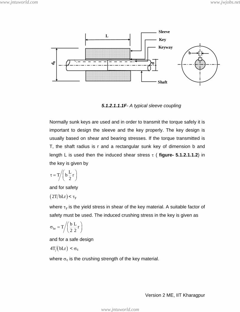
5.1.2.1.1.1F- A typical sleeve coupling
Normally sunk keys are used and in order to transmit the torque safely it is
important to design the sleeve and the key properly. The key design is
usually based on shear and bearing stresses. If the torque transmitted is
T, the shaft radius is r and a rectangular sunk key of dimension b and
length L is used then the induced shear stress τ ( figure- 5.1.2.1.1.2) in
the key is given by
LT b r2
⎛ ⎞τ = ⎜ ⎟⎝ ⎠
and for safety
( )2T bLr < τy
where τy is the yield stress in shear of the key material. A suitable factor of
safety must be used. The induced crushing stress in the key is given as
brb LT r2 2
⎛ ⎞σ = ⎜ ⎟⎝ ⎠
and for a safe design
( )4T bLr < σc
where σc is the crushing strength of the key material.
Version 2 ME, IIT Kharagpur
www.jntuworld.com
www.jntuworld.com
www.jwjobs.net

Shear plane
Crushing plane
L
b
b
Key
5.1.2.1.1.2F- Shear and crushing planes in the key.
The sleeve transmits the torque from one shaft to the other. Therefore if di
is the inside diameter of the sleeve which is also close to the shaft
diameter d (say) and d0 is outside diameter of the sleeve, the shear stress
developed in the sleeve is ( )
0sleeve 4 4
0 i
16Tdd d
τ =π −
and the shear stress in the
shaft is given by shaft 3i
16Td
τ =π
. Substituting yield shear stresses of the
sleeve and shaft materials for τsleeve and τshaft both di and d0 may be
evaluated.
However from the empirical proportions we have:
d0 = 2di + 12.5 mm and L=3.5d.
These may be used as checks.
5.1.2.1.2 Sleeve coupling with taper pins
Torque transmission from one shaft to another may also be done using
pins as shown in figure-5.1.2.1.2.1.
Version 2 ME, IIT Kharagpur
www.jntuworld.com
www.jntuworld.com
www.jwjobs.net
L
d 0 d
Sleeve
a a
Shaft
Pin
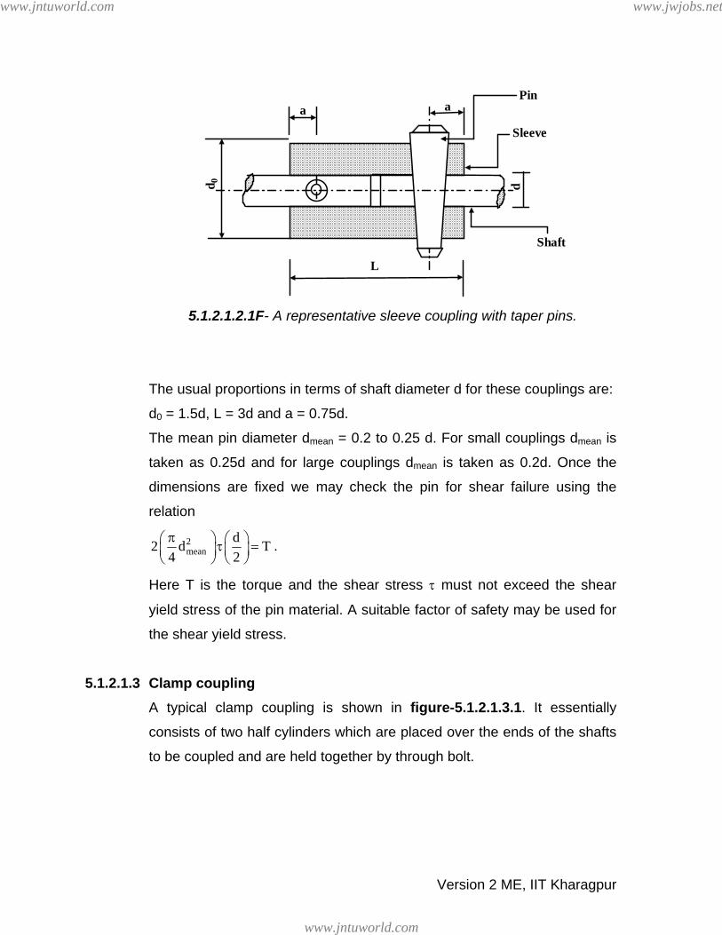
5.1.2.1.2.1F- A representative sleeve coupling with taper pins.
The usual proportions in terms of shaft diameter d for these couplings are:
d0 = 1.5d, L = 3d and a = 0.75d.
The mean pin diameter dmean = 0.2 to 0.25 d. For small couplings dmean is
taken as 0.25d and for large couplings dmean is taken as 0.2d. Once the
dimensions are fixed we may check the pin for shear failure using the
relation
2mean
d2 d T4 2π⎛ ⎞ ⎛ ⎞τ =⎜ ⎟ ⎜ ⎟
⎝ ⎠ ⎝ ⎠.
Here T is the torque and the shear stress τ must not exceed the shear
yield stress of the pin material. A suitable factor of safety may be used for
the shear yield stress.
5.1.2.1.3 Clamp coupling A typical clamp coupling is shown in figure-5.1.2.1.3.1. It essentially
consists of two half cylinders which are placed over the ends of the shafts
to be coupled and are held together by through bolt.
Version 2 ME, IIT Kharagpur
www.jntuworld.com
www.jntuworld.com
www.jwjobs.net

5.1.2.1.3.1F- A representative clamp coupling
The length of these couplings ‘L’ usually vary between 3.5 to 5 times the
and the outside diameter ‘d0’ of the coupling sleeve between 2 to 4 times
the shaft diameter d. It is assumed that even with a key the torque is
transmitted due to the friction grip. If now the number of bolt on each half
is n, its core diameter is dc and the coefficient of friction between the shaft
and sleeve material is μ we may find the torque transmitted T as follows:
The clamping pressure between the shaft and the sleeve is given by
( )2tc
np x d x dL / 22 4
π= σ
where n is the total number of bolts, the number of effective bolts for each
shaft is n/2 and σt is the allowable tensile stress in the bolt. The tangential
force per unit area in the shaft periphery is F = μ p. The torque transmitted
can therefore be given by dL dT p2 2
.π= μ .
5.1.2.1.4 Ring compression type couplings The coupling (figure-5.1.2.1.4.1) consists of two cones which are placed on
the shafts to be coupled and a sleeve that fits over the cones. Three bolts
Version 2 ME, IIT Kharagpur
www.jntuworld.com
www.jntuworld.com
www.jwjobs.net
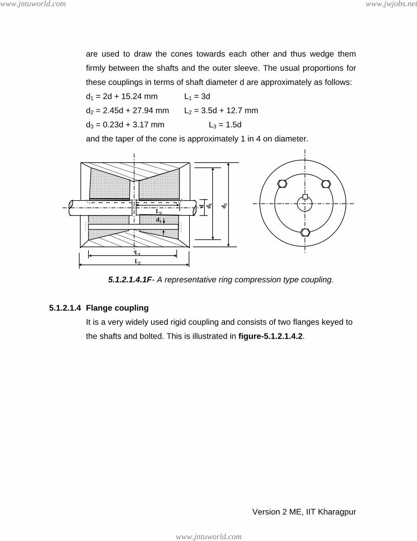
are used to draw the cones towards each other and thus wedge them
firmly between the shafts and the outer sleeve. The usual proportions for
these couplings in terms of shaft diameter d are approximately as follows:
d1 = 2d + 15.24 mm L1 = 3d
d2 = 2.45d + 27.94 mm L2 = 3.5d + 12.7 mm
d3 = 0.23d + 3.17 mm L3 = 1.5d
and the taper of the cone is approximately 1 in 4 on diameter.
d
L1
L2
L3
d3d 2d 1
5.1.2.1.4.1F- A representative ring compression type coupling.
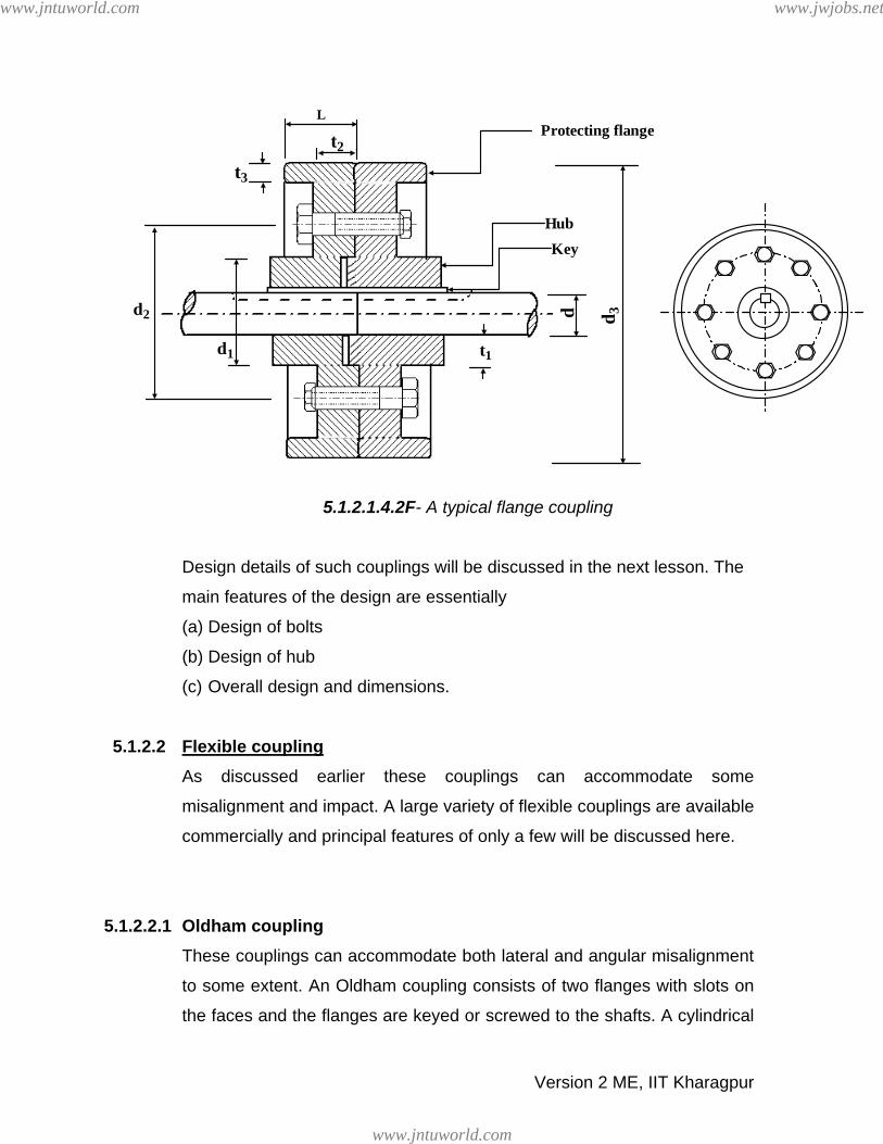
5.1.2.1.4 Flange coupling It is a very widely used rigid coupling and consists of two flanges keyed to
the shafts and bolted. This is illustrated in figure-5.1.2.1.4.2.
Version 2 ME, IIT Kharagpur
www.jntuworld.com
www.jntuworld.com
www.jwjobs.net
d 3
t1
KeyHub
Protecting flange
d1
d2
t3
t2
L
d
5.1.2.1.4.2F- A typical flange coupling
Design details of such couplings will be discussed in the next lesson. The
main features of the design are essentially
(a) Design of bolts
(b) Design of hub
(c) Overall design and dimensions.
5.1.2.2 Flexible coupling As discussed earlier these couplings can accommodate some
misalignment and impact. A large variety of flexible couplings are available
commercially and principal features of only a few will be discussed here.
5.1.2.2.1 Oldham coupling These couplings can accommodate both lateral and angular misalignment
to some extent. An Oldham coupling consists of two flanges with slots on
the faces and the flanges are keyed or screwed to the shafts. A cylindrical
Version 2 ME, IIT Kharagpur
www.jntuworld.com
www.jntuworld.com
www.jwjobs.net
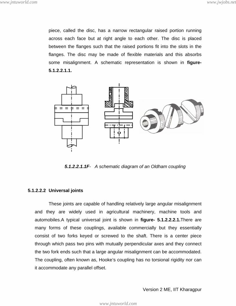
piece, called the disc, has a narrow rectangular raised portion running
across each face but at right angle to each other. The disc is placed
between the flanges such that the raised portions fit into the slots in the
flanges. The disc may be made of flexible materials and this absorbs
some misalignment. A schematic representation is shown in figure- 5.1.2.2.1.1.
5.1.2.2.1.1F- A schematic diagram of an Oldham coupling
O
5.1.2.2.2 Universal joints
These joints are capable of handling relatively large angular misalignment
and they are widely used in agricultural machinery, machine tools and
automobiles.A typical universal joint is shown in figure- 5.1.2.2.2.1.There are
many forms of these couplings, available commercially but they essentially
consist of two forks keyed or screwed to the shaft. There is a center piece
through which pass two pins with mutually perpendicular axes and they connect
the two fork ends such that a large angular misalignment can be accommodated.
The coupling, often known as, Hooke’s coupling has no torsional rigidity nor can
it accommodate any parallel offset.
Version 2 ME, IIT Kharagpur
www.jntuworld.com
www.jntuworld.com
www.jwjobs.net

5.1.2.2.2.1F- A typical universal joint (Ref. [2])
5.1.2.2.2 Pin type flexible coupling One of the most commonly used flexible coupling is a pin type flexible
flange coupling in which torque is transmitted from one flange to the other
through a flexible bush put around the bolt. This is shown in the next
lesson and is shown in figure-5.2.2.1. These are used when excessive misalignment is not expected such as a
coupling between a motor and a generator or a pump mounted on a
common base plate. Detail design procedure for these couplings will be
discussed in the next lesson.
5.1.3 Summary of this Lesson Basic function of shaft couplings, their types and uses have been
discussed in this lesson. Among the rigid couplings some details of sleeve
couplings with key or taper pins, clamp couplings, ring compression type
couplings and flange couplings have been described. Among the flexible
couplings the Oldham coupling and universal joints are described and the
functions of pin type flexible couplings are given briefly.
Version 2 ME, IIT Kharagpur
www.jntuworld.com
www.jntuworld.com
www.jwjobs.net


