9.7.2 R&D Hydrogen Delivery System Aims of the R&D hydrogen delivery system a) Manufacture a development model hydrogen delivery system that can be upgraded to be the first MICE model. b) To develop a robust safety case to go with the design and have this reviewed. c) To develop a control system that will be compatible with the MICE control system that will safely operate the hydrogen delivery system. The absorber for MICE may require operation with either hydrogen or helium. To cover both options a cryocooler capable of operation at below 4K will be used. Overview of the system MICE will require three hydrogen systems – these will be independent of each other to reduce problems associated with consequential effects. The absorber for MICE requires 21 litres of liquid hydrogen in each of three absorbers. After an analysis of previous accidents associated with hydrogen systems the decision was taken to minimise the venting of hydrogen. The hydrogen is stored in a hydride bed until required. After use, it is re-absorbed. The hydride bed is not passive it evolves hydrogen when hot and absorbs it when cold. The heating and cooling function is provided by a heater/chiller unit that circulates water through the bed. In order to prevent the ingress of oxygen into the system in areas where there are personnel, all of the pipework outside the hood will be jacketed with Argon. Two pipes are used to and from the buffer vessel in case of plugging at low temperatures. The volumes and pipework are located inside a cabinet. The air flow will take any hydrogen out through the vent. This also provides an additional safety barrier to sources of ignition. Most of the equipment sits under an extraction hood this takes air to outside the hall where it is vented. The R&D system described here consists of two main components: 9.7.1
Transcript
9.7.2 R&D Hydrogen Delivery System
Aims of the R&D hydrogen delivery system
a) Manufacture a development model hydrogen delivery system that can be upgraded to be the first MICE model.
b) To develop a robust safety case to go with the design and have this reviewed.c) To develop a control system that will be compatible with the MICE control system that will
safely operate the hydrogen delivery system.
The absorber for MICE may require operation with either hydrogen or helium. To cover both options a cryocooler capable of operation at below 4K will be used.
Overview of the system
MICE will require three hydrogen systems – these will be independent of each other to reduce problems associated with consequential effects. The absorber for MICE requires 21 litres of liquid hydrogen in each of three absorbers.
After an analysis of previous accidents associated with hydrogen systems the decision was taken to minimise the venting of hydrogen. The hydrogen is stored in a hydride bed until required. After use, it is re-absorbed. The hydride bed is not passive it evolves hydrogen when hot and absorbs it when cold. The heating and cooling function is provided by a heater/chiller unit that circulates water through the bed.
In order to prevent the ingress of oxygen into the system in areas where there are personnel, all of the pipework outside the hood will be jacketed with Argon.
Two pipes are used to and from the buffer vessel in case of plugging at low temperatures.The volumes and pipework are located inside a cabinet. The air flow will take any hydrogen out through the vent. This also provides an additional safety barrier to sources of ignition.Most of the equipment sits under an extraction hood this takes air to outside the hall where it is vented.
The R&D system described here consists of two main components:
Hydrogen delivery system – This will be the first prototype for MICE and the components will be used in the first full MICE hydrogen system.
Test cryostat – This will mimic the final absorber system but will not have absorber windows.
Hydrogen zones definition according to RAL Safety Code No.1:
Zone 0: An area or enclosed space within which any flammable or explosive substance, whether gas, vapour, or volatile liquid, is continuously present in concentrations within the lower and upper limits of flammability. Zone 1: An area within which any flammable or explosive substance, whether gas, vapour, or volatile liquid is processed, handled or stored and where during normal operations an explosive or ignitable concentration is likely to occur in sufficient quantity to produce a hazard. Zone 2: An area within which any flammable or explosive substance whether gas, vapour or volatile liquid, although processed or stored, is so well under conditions of control that the production (or release) of an explosive or ignitable concentration in sufficient quantity to constitute a hazard is only likely under abnormal conditions.
9.7.1
There are no Zone 0 areas. The design features are such that Zone 1 is only where there are no people present. The hydrogen in the zone 1 areas is only present during initial conditioning of the beds and during the purge process.
Electrical Safety
RAL Safety Code No.1 says:
The conditions described as Zone 0 normally require the total exclusion of any electrical equipment. Where this proves to be impracticable special measures such as pressurisation or the use of intrinsically safe equipment may be used.
A risk of the nature described under Zone 1 can usually be met by the use of flameproof or intrinsically safe equipment. An alternative is to segregate, ventilate or pressurise the electrical equipment or room.
In Zone 2 areas specially designed electrical equipment is necessary.
Intrinsic Safety A circuit or piece of electrical apparatus is said to be intrinsically safe when the energy produced by a spark is insufficient to ignite a flammable concentration. The minimum ignition energy for hydrogen is 0.019mJ.
Pressurisation Uncontaminated air or an inert gas such as nitrogen shall be supplied to the apparatus. The internal pressure must be maintained above the ambient pressure.
Segregation It may be possible to locate switches, control equipment, motors etc. in a separate room within a high risk area (Zone 0 or 1). The room should be kept under slight positive air pressure using an uncontaminated air supply; the air pressure should be monitored and the signal connected to an alarm.
Hydrogen test area
The hydrogen test area will be located in the hall in the position shown for the R&D phase. A ventilation system will be installed as shown for the ventilation system. An additional vent will be installed in the roof to remove any loose hydrogen or helium.
9.7.2
Figure 9.7.2-1 Test area for the hydrogen R&D
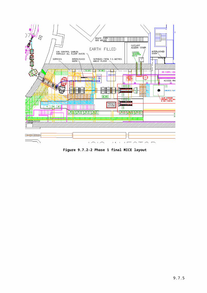
For the final phases of MICE when three hydrogen delivery systems are required the position will be at the same location. This places the hydrogen system on the other side of the hall to the high power RF systems for the cavities.
9.7.3
Figure 9.7.2-2 Phase 1 final MICE layout
9.7.4
Hydrogen Delivery System
Pipe size calculations
Of concern in the safety case is the worst case scenario where vacuum is lost in the region surrounding the absorber. Previous experiments on dewars have shown that this will put a heat load on the absorber of around 3.6 W/cm2. For our analysis1 a safety factor of 2 has been applied to this figure. All the pipework at room temperature that carries the hydrogen exhaust in the event of a failure is DN25. At low temperatures this is reduced to 17mm internal diameter.
0
0.5
1
1.5
2
2.5
3
0.01 0.015 0.02 0.025 0.03 0.035
Pipe diameter m
Pres
sure
dro
p B
ar
Gas at 300K
Choked flow RT
Gas at 40K
Figure 9.7-3 Pressure rise in pipes with catastrophic loss of vacuum
The criterion is to keep the pressure in the absorber low enough to prevent rupture in the absorber membrane. The pressure drop as a function of pipe diameter is shown in the above figure.
1 PipePressureDropsHydrogenV2.xls
9.7.5
Figure 9.7-4. The process diagram.
Relief Valves
9.7.6
There are several stages of relief valves:As the pressure rises the first stage is to vent the absorber back into the hydride bed. This will prevent any loss of hydrogen to the surrounding air and remove the possibility of dangerous air/hydrogen mixture forming. During normal operation of the hydrogen system the hydride bed is cooler so that the pressure inside the bed is very low. The pressure relief valves are set at 1 bar differential. This will allow operation of the absorber up to 20K before the hydrogen is vented back into the bed.
If the hydride bed is unable to cope with the flow rate then a secondary system vents the hydrogen into the hydrogen exhaust trunking where it is vented outside the hall. Hydrogen sensors will give a warning. This is set to 0.5 bar above atmospheric pressure. This will vent when the absorber pressure rises above 1.5bar. In addition to the relief valve a burst disc gives further protection on this circuit.A buffer volume is used to damp out any fluctuations. This is located under the vent hood.
Relief valves are also located on the cryostat volume in case of loss of hydrogen into this area.
A key point of the design is that these make certain operations of the gas control system independent of the control system. If we take an example:
In the event of a moderate vacuum leak the system pressure will rise until 1 bar is reached when the pressure relief valve to the hydrogen bed will open and the gas will be absorbed by the hydride bed without any increase in pressure. If the leak is worse and the hydrogen evolution is so high that the hydride bed is incapable of absorbing at a quick enough rate then the second relief valve will open venting the hydrogen into the duct. All of these operations are passive and do not require the intervention of the control system.
Relief Valve selectionThe relief valves need to be of high quality to protect the absorber windows. Tyco valves have the desired characteristics.Tyco (Crosby) valves – key points:
Pilot valves – quick acting 3% tolerance on set pressure Closes at 95% of set pressure Response time is <0.5s Valves re-seat on elastomers 91&94 valves usable to 20K (although situated at RT)
Buffer Volume
The buffer volume is a device to prevent rapid pressure rises in the system. The calculations2 assume :
Assumes mixing of gas - cold from absorber + buffer volume Temperature in buffer is calculated on basis of constant Cv - this is optimistic for Tgas ~50K
but pretty good for Tgas >100K For large outflow through the relief valve the algorithm is not correct because the valve
essentially shuts Buffer volume gives a huge safety margin over just the pipe system with vol ~ 0.1m^3 for 50m
of 50mm dia pipe The buffer vessel will keep the gas warmer due to its thermal mass - this is not included - it will
increase the pressure rise Typically with 1m3 Tgas ~100K pressure rise rate is 0.1 bar/sec valve opening time of 0.1-0.2
sec would be OK
2 Pressure rise buffer.xls
9.7.7
0
0.2
0.4
0.6
0.8
1
1.2
1.4
1.6
1.8
2
0 5 10 15 20
tim e secs
pres
sure
Pa
0
50
100
150
200
250
300
350
tem
pera
ture
Figure 9.7.2- 5 Pressure rise in buffer volume
The input parameters to the calculations are:
Latent heat 446000 J/kgPower into liquid 10179 WHydrogen boiled off (kg/s)
0.022823 Kg/s
Start mass of liquid 1.544 KgLiquid density 70.288Start pressure (bar) 0.5Rgas 4157dt 0.2Buffer vol 1 M^3density 300K 0.08 Kg/
m^3relief valve pressure 1.60E+05 Paoutlet mass flow 1.20E-02 Kg/s
Pumping and purging
There are two vacuum pumps located in the system to pump and purge prior to running after maintenance and to service the vacuum around the dummy absorber. Both of these are vented through the extraction system. VP01 will also be used during the hydride bed activation process.
Ventilation and air extraction
The pipework panel is situated under a ventilation hood which exhausts outside the building. Nitrogen gas is introduced into the line to reduce the risk of a flammable mixture being present in the hall.
Hydride Bed
General Description of Hydride Bed
9.7.8
The hydride bed is used to store hydrogen in a safe form. The bed itself is a commercial item and several firms supply them. These firms were approached but only one was able to meet the MICE requirements.The operation of the bed is quite simple – when warmed the bed evolves hydrogen gas- when cooled, it absorbs hydrogen. The difference between the two temperatures is in the region of 30C. The nominal figures for the absorbtion temperature is -10C and +20C for the evolution temperature. The exact values are subject to change as we are advised that these will depend on the slight variations inherent in the manufacture of the hydride. Heating and cooling is effected by the use of a water circulating loop from a heater/chiller unit. For the lower temperatures anti-freeze will be added to the water.
Specification of the hydride bed
Hydrogen Storage Capacity 20 Nm3
Tank number/system 1
Tank Description:Heat Transfer Medium WaterMH Weight 155kgTank Structure Shell & Tube typeDimensions φ216.3×L1600(mm) ( not including
attachments )Tank Total Weight 220 Kg
Operating Condition:Charging Gas Component Hydrogen of 99.99% purity Charging Gas Pressure 1.2 barAHydrogen Charging Rate 70NL/min (up to 90% of Storage Capacity)Discharging Gas Pressure 1.2 barAHydrogen Discharging Rate 70NL/min (up to 90% of Storage Capacity)
Utility Requirements:Cooling Medium Water Below –10C (At 20L/min)Heating Medium Above 20C (At 20L/min)Design Code (AD Merkblaetter )Certification (Declaration of Conformity to Pressure
Equipment Directive 97/23/EC Certified by a Notified Body)
(1600)
φ216.3
140
(1810)
2-Rc3/4Relief valveFilter
Valve
Figure 9.7.2-6 Dimensions of the Hydride Tank
9.7.9
0 50 100 150 20010-2
10-1
100
17℃
10℃
0.12MPa
-10℃
30℃
Hydrogen Pressure (MPa)
Hydrogen Content (cc/g)
Figure 9.7.2-7 PCT curve for the hydride bed
Installation, activation and precautions during use
The hydride is stored inside the tank in a manner such that it needs to be installed in a horizontal manner.Activation of the bed needs to be done before use and consists of the following steps:
Pump out absorber Heat to 60-80C Add H2 to about 1.2 bar Leave to soak for 8 hours
After activation the hydride bed is flammable but it needs an activation source.
Any ingress of air should be avoided as this oxidises the material. The oxidation rate is, however, low.
20 litres liquid = 16,000 normal litres gas the hydride bed will absorb this in under 4 hours.
9.7.10
R&D Test Cryostat
The test cryostat is representative of the absorber and will carry, as near as can be defined at this stage, the same instrumentation set plus additional sensors for tes purposes. The absorber is represented as a plain can containing the 22litres of liquid hydrogen (or helium). The facility exists to cool the volume with an external cooling loop to speed up operation. There are two lines exiting the condenser volume.
1120
Ø 580
1120
Ø 580
Figure 9.7.2-8 Hydrogen R&D system test cryostat outline
9.7.11
Condenser
LH2 dummy absorber
Level sensors
Cryocooler SRDK-4151.5 W @4.2K35/45 W @50K
Radiation shield
Hydrogen inlet and outlet
He inlet and outlet
Cu bottom plate with heat exchanger
Condenser
LH2 dummy absorber
Level sensors
Cryocooler SRDK-4151.5 W @4.2K35/45 W @50K
Radiation shield
Hydrogen inlet and outlet
He inlet and outlet
Cu bottom plate with heat exchanger
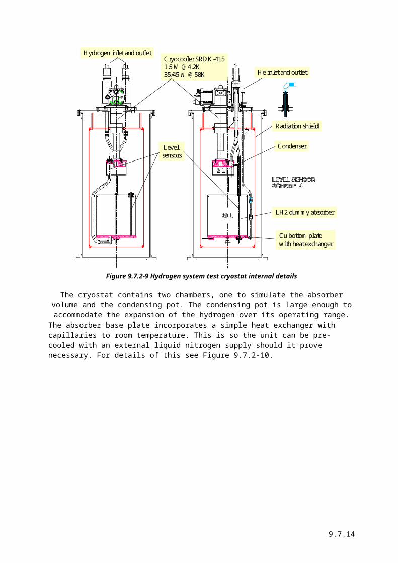
Figure 9.7.2-9 Hydrogen system test cryostat internal details
The cryostat contains two chambers, one to simulate the absorber volume and the condensing pot. The condensing pot is large enough to accommodate the expansion of the hydrogen over its operating range.The absorber base plate incorporates a simple heat exchanger with capillaries to room temperature. This is so the unit can be pre-cooled with an external liquid nitrogen supply should it prove necessary. For details of this see Figure 9.7.2-10.
9.7.12
Cu bottom plate with heat exchanger
Cartridge heaters
Finned top plateof condenser
Cu bottom plate with heat exchanger
Cartridge heaters
Finned top plateof condenser
Figure 9.7.2-10 Details of the condensing plate and absorber base
Thermal aspects
A preliminary thermal model of the cryostat shows that the heat loads on the cryocooler are small compares to its rated performance at the temperatures of operation.
Cryocooler
The cryocooler selected is a Sumitomo SRDK-415 unit which has a base temperature of below 3K. This will allow operation of the cryostat with either helium or hydrogen. For operation with hydrogen, a control system will be used to keep the cold head above the freezing point. The heater will need to be sized to accommodate the cooling power of the refrigerator around 14-20K region. The size of the heater is estimated by extrapolating the cooling power from declared data to that region. The data is concentrated in the region around 4K so the extrapolation is questionable, it does show that a heater with a rating at low temperature of around 25W will be required. This is shown in Figure 9.7.2-11.
9.7.13
y = 1.0857x + 2.8286
0
5
10
15
20
25
0 2 4 6 8 10 12 14 16 18
Power W
Tem
pera
ture
K
Figure 9.7.2-11 Cooling power of the Sumitomo refrigerator
9.7.14
Liquid level sensors
For the test cryostat we have baselined capacitance level sensors from AMI (Figure 9.7.2-12). These are rated for use with hydrogen and will interface with the control system.Parameters for the level sensors chosen to follow.
Figure 9.7.2-12 AMI Liquid level sensors
Hydrogen and Oxygen Sensors
The preliminary HAZOP process identified a need for hydrogen and oxygen sensors on the buffer tank. To date no hydrogen or oxygen sensors suitable for use in a vacuum have been identified. There is a provision to install a mass spectrometer on the buffer tank but this is not an alarm system. This area needs more work.
Control System
The control system will be based on Labview for the R&D tests. Once the algorithms are developed these will be moved over to an industry standard platform and software. It should be noted that at the time of writing the control system and interlocks are in an early stage of definition so no firm decisions have been made in this area.Control logic
Logic to be included
Preliminary HAZOP
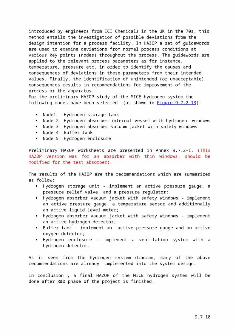
The Hazard and Operability analysis (HAZOP) is a well known technique to assess a plant’s safety and operability. First introduced by engineers from ICI Chemicals in the UK in the 70s, this method entails the investigation of possible deviations from the design intention for a process facility. In HAZOP a set of guidewords are used to examine deviations from normal process conditions at various key points (nodes) throughout the process. The guidewords are applied to the relevant process parameters as for instance, temperature, pressure etc. in order to identify the causes and consequences of deviations in these parameters from their intended values. Finally, the identification of unintended (or unacceptable) consequences results in recommendations for improvement of the process or the apparatus.For the preliminary HAZOP study of the MICE hydrogen system the following modes have been selected (as shown in Figure 9.7.2-13):
Node1 : Hydrogen storage tank
9.7.15
Node 2: Hydrogen absorber internal vessel with hydrogen windows Node 3: Hydrogen absorber vacuum jacket with safety windows Node 4: Buffer tank Node 5: Hydrogen enclosure
Preliminary HAZOP worksheets are presented in Annex 9.7.2-1. (This HAZOP version was for an absorber with thin windows, should be modified for the test absorber).
The results of the HAZOP are the recommendations which are summarized as follow: Hydrogen storage unit – implement an active pressure gauge, a pressure relief valve and a
pressure regulator; Hydrogen absorber vacuum jacket with safety windows – implement an active pressure gauge,
a temperature sensor and additionally an active liquid level meter; Hydrogen absorber vacuum jacket with safety windows – implement an active hydrogen
detector; Buffer tank – implement an active pressure gauge and an active oxygen detector; Hydrogen enclosure – implement a ventilation system with a hydrogen detector.
As it seen from the hydrogen system diagram, many of the above recommendations are already implemented into the system design.
In conclusion , a final HAZOP of the MICE hydrogen system will be done after R&D phase of the project is finished.
9.7.16
Tchill
Pressuregauge
Non-return valveP P VP Vacuum pumpBursting diskPressure
relief valveValvePressureregulator
CoolantOut In
Test absorber assembly
Metal Hydride storage unit
(20m3 capacity)
Purge valve
0.5 bar
0.9 bar
H2 Detector
P
P
VP1
VP2
Purge valve
Chiller/Heater Unit
1 bar
PP
0.5 bar
0.9 bar Helium supply
Hydrogen supply
High level vent
Buffer vessel
Vent outsideflame arrester
Extract hoodH2Detector
PP
Nitrogen supply
PP
PP
1 m3
Hydrogen zone 2
Vent manifold Vent manifold
P1
PV1
PV7
PV8
PV2
PV3
PV4
HV1
Fill valve
Tbed
HV2
HV3
P3
P
P2
PV6
High level vent
Non returnvalve
0.1 bar
Mass spectrometer
M. F.M.
Mass flow meter
Node 1
Node 2
Node3
Node 4
Node 5
Tchill
Pressuregauge
Non-return valveP P VP Vacuum pumpBursting diskPressure
relief valveValvePressureregulator
CoolantOut In
Test absorber assembly
Metal Hydride storage unit
(20m3 capacity)
Purge valve
0.5 bar
0.9 bar
H2 Detector
P
P
VP1
VP2
Purge valve
Chiller/Heater Unit
1 bar
PP
0.5 bar
0.9 bar Helium supply
Hydrogen supply
High level vent
Buffer vessel
Vent outsideflame arrester
Extract hoodH2Detector
PP
Nitrogen supply
PP
PP
1 m3
Hydrogen zone 2
Vent manifold Vent manifold
P1
PV1
PV7
PV8
PV2
PV3
PV4
HV1
Fill valve
Tbed
HV2
HV3
P3
P
P2
PV6
High level vent
Non returnvalve
0.1 bar
Mass spectrometer
M. F.M.
Mass flow meterTchill
Pressuregauge
Non-return valveP P VP Vacuum pumpBursting diskPressure
relief valveValvePressureregulator
CoolantOut In
Test absorber assembly
Metal Hydride storage unit
(20m3 capacity)
Purge valve
0.5 bar
0.9 bar
H2 DetectorH2 Detector
P
P
VP1
VP2
Purge valve
Chiller/Heater Unit
1 bar
PP
0.5 bar
0.9 bar Helium supply
Hydrogen supply
High level vent
Buffer vessel
Vent outsideflame arrester
Extract hoodH2DetectorH2Detector
PP
Nitrogen supply
PP
PP
1 m3
Hydrogen zone 2
Vent manifold Vent manifold
P1
PV1
PV7
PV8
PV2
PV3
PV4
HV1
Fill valve
Tbed
HV2
HV3
P3
P
P2
PV6
High level vent
Non returnvalve
0.1 bar
Mass spectrometer
M. F.M.
Mass flow meter
Node 1
Node 2
Node3
Node 4
Node 5
Figure 9.7.2-13. Hydrogen system diagram used for HAZOP analysis
9.7.17
Annex 9.7.2-1. Preliminary HAZOP worksheets
Node 1: Hydrogen metal hydride storage unit (Node 1)Intent: To keep hydrogen gas in the tank - absorber vessel closed system.No Parameter Guide word Cause Consequence Safeguards Recommendations2 Pressure Higher Fill valve is accidentally open
or leaking.Tank is overheated.
1-2. Absorber windows can brake
Pressure regulator to reduce the pressure on the line to the absorber.Pressure relief valve to vent outside.Active pressure gauge to trigger an alarm.
Implement a pressure regulator on the line to the absorber.Implement a pressure relief valve.Implement an active pressure gauge.
9.7.18
Node 2: Hydrogen absorber internal vessel with hydrogen windows.Intent: To keep hydrogen liquid inside hydrogen absorber module.No Parameter Guide word Cause Consequence Safeguards Recommendations1 Temperature Lower Too much cooling power
from the He cooling system.
Pressure in the hydrogen system drops.
Pressure gauge to trigger an alarm.Temperature sensor to trigger an alarmAdditional: Liquid hydrogen level meter to trigger an alarm.
Implement both the active pressure gauge and the temperature sensor.Additional:Implement an active liquid level meter.
2 Temperature Higher Not enough cooling power from the He cooling system.Power cut.
Temperature sensor to trigger an alarmAdditional: Liquid hydrogen level meter to trigger an alarm.Pressure gauge to trigger an alarm.
Implement both the active pressure gauge and the temperature sensor.Additional : Implement an active liquid level meter.
3 Pressure Lower Window is leaking or broken.Pipe is leaking.Hydrogen tank is leaking.Absorber is over cooled.
1. Hydrogen leaks into vacuum vessel.2-3. Hydrogen is leaking out.4. Pressure in the system drops and air can leak in the system in case if the system seal is broken.
Hydrogen detector to trigger an alarm.Hydrogen ventilation system collects and vents hydrogen out.Temperature sensor to trigger an alarm.
Implement an active hydrogen detector.Implement hydrogen collection and ventilation system. Implement a temperature sensor.
9.7.19
Node 3: Hydrogen absorber vacuum jacket with safety windows.Intent: - To insulate thermally the internal hydrogen vessel . - To provide additional barrier for air .
No Parameter Guide word Cause Consequence Safeguards Recommendations1 Pressure Higher 1. Hydrogen window is
broken2. Vacuum pump failure
Hydrogen bursts into vacuum jacketVacuum drops.
Pressure relief valve to dump hydrogen into a buffer tank and then to vent it outside.
Implement a buffer tank.
2 Hydrogen concentration
Higher Hydrogen leaks due to window is broken .
An explosive mixture can be formed if there is an air leak in as well.
Active hydrogen sensor detects hydrogen and trigger s an alarm.
Implement an active hydrogen sensor.
9.7.20
Node 4: Buffer tank.Intent: To quickly relief pressure in the absorber module in case of window burst . No Parameter Guide word Cause Consequence Safeguards Recommendations1 Pressure Higher 1. Venting path is
blocked.
2. Tank is leaking.
3. Vacuum pump failure
Absorber vacuum jacket windows can break.
Buffer tank can’t be used for dumping hydrogen in case of accident with absorber.
Active pressure gauge triggers an alarm.
Oxygen sensor triggers an alarm.
Use a spare pump.
Implement an active pressure gauge.
Implement an active oxygen sensor.
Keep a spare pump.
9.7.21
Node 5: Hydrogen enclosure.Intent: To localize and vent hydrogen in case of hydrogen leak . No Parameter Guide word Cause Consequence Safeguards Recommendations1 Hydrogen
concentrationHigher 1. Hydrogen leaks out
absorber module2. Hydrogen leaks out hydrogen pipes3. Hydrogen leaks out storage unit.
1-3. Explosive oxygen-hydrogen mixture can be formed
Ventilation system to quickly vent hydrogen out.Hydrogen detector to trigger an alarm and to start a high rate mode for the ventilation system.
Implement ventilation system equipped with hydrogen detector.