1 Weekly Report Weekly Report on on GOES-14 PLT GOES-14 PLT Science Test Science Test NOAA / NESDIS / STAR NOAA / NESDIS / STAR X. Wu, G. Rancic, F. X. Wu, G. Rancic, F. Yu Yu December 18, 2009 December 18, 2009
Transcript
1
Weekly Report Weekly Report on on
GOES-14 PLT GOES-14 PLT Science TestScience Test
NOAA / NESDIS / STARNOAA / NESDIS / STAR
X. Wu, G. Rancic, F. YuX. Wu, G. Rancic, F. Yu
December 18, 2009December 18, 2009
2
1. Initial Results of GEO-GEO 1. Initial Results of GEO-GEO Comparison for GOES-14 PLTComparison for GOES-14 PLT
Purpose:Purpose: Confirm that GOES-14 measurements are comparable Confirm that GOES-14 measurements are comparable
with those currently operational (GOES-11/12) to with those currently operational (GOES-11/12) to ensure operation continuity.ensure operation continuity.
Method:Method: Collect the collocated data by both GEOs along a Collect the collocated data by both GEOs along a
narrow strip (~40 km) in the middle of the two to narrow strip (~40 km) in the middle of the two to minimize difference due to viewing geometry.minimize difference due to viewing geometry.
Data:Data: Along 120W for GOES-11/14, 90W for GOES-12/14, 0-Along 120W for GOES-11/14, 90W for GOES-12/14, 0-
50N, every 30 minutes, 2009/12/01 to 2010/01/05.50N, every 30 minutes, 2009/12/01 to 2010/01/05.
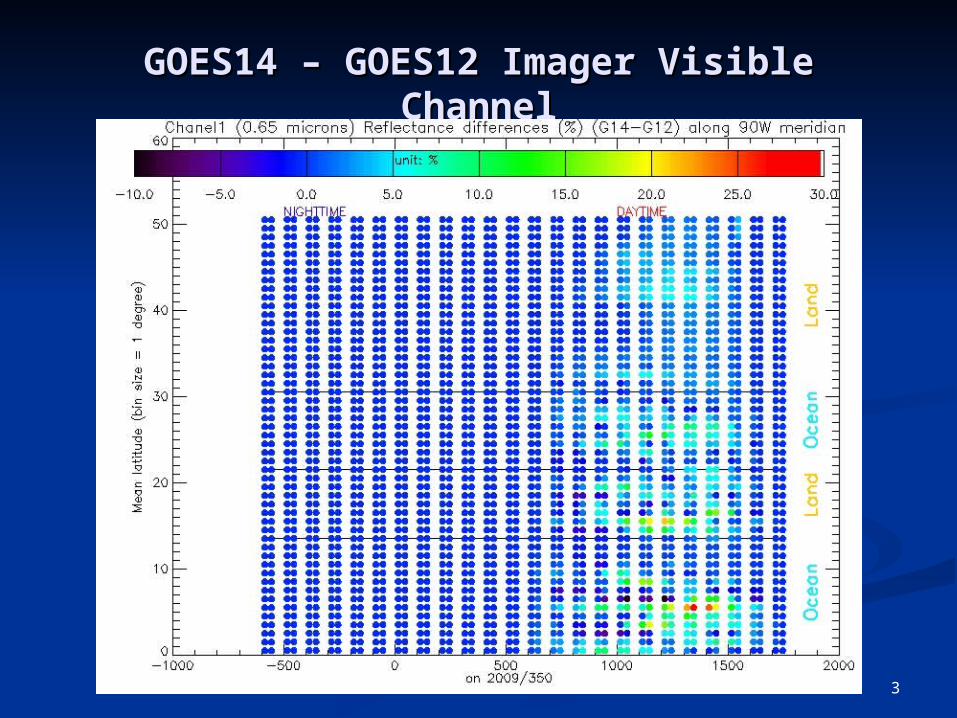
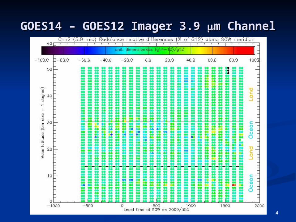
Analysis:Analysis: This analysis presents comparison of two channels for This analysis presents comparison of two channels for
GOES-12/14 on Dec 16, when GOES-14 emulated GOES-GOES-12/14 on Dec 16, when GOES-14 emulated GOES-12.12.
Calibration (Wu et al 2009).Calibration (Wu et al 2009).
DataData GOES Imager IR data, GOES Imager IR data,
AIRS/IASI data since Oct. 28, AIRS/IASI data since Oct. 28, 2009 2009
GOES Sounder and IASI data GOES Sounder and IASI data between Nov. 30, 2009-Dec. between Nov. 30, 2009-Dec. 13, 200913, 2009
GOES-14 Imager spectral response functions and the simulated AIRS/IASI spectra
GOES-14 Imager (upper) and Sounder (lower) spectral response functions and the simulated AIRS/IASI spectra
2. Initial Bias Evaluation of 2. Initial Bias Evaluation of GOES-14 IR ChannelsGOES-14 IR Channels
7
•More at http://www.star.nesdis.noaa.gov/smcd/spb/fwu/homepage/GSICS_GOES14_AIRS_IASI.php
•Large difference for 3.8 m channel may be due to the BRDF of solar reflection•Large bias (1 K) for water vapor channel•Unusually large and unstable bias for Ch. 10.7 m in November•Smaller bias (-0.5K) for 13.3 m channel
2.2 GOES-14 Sounder vs 2.2 GOES-14 Sounder vs IASIIASI
Much less bias for SW channels
9
Purpose:Purpose: Confirm compliance of instrument spec.Confirm compliance of instrument spec. Establish benchmark for future Instrument Performance Establish benchmark for future Instrument Performance
Monitoring.Monitoring.
Methods:Methods: Standard deviation of space looks.Standard deviation of space looks. Standard deviation of blackbody looks will follow.Standard deviation of blackbody looks will follow.
DataData 11/30 – 12/1411/30 – 12/14
Analysis:Analysis: Mean noises are presented. Agree with CIMSS results.Mean noises are presented. Agree with CIMSS results. Detailed analysis will follow.Detailed analysis will follow.
3. Initial Noise Evaluation 3. Initial Noise Evaluation of of
GOES-14 IR ChannelsGOES-14 IR Channels
10
Preliminary ResultsPreliminary ResultsInitial Evaluation of GOES-14 Bias
performance anomaly.performance anomaly. Diagnose for root causeDiagnose for root cause Verify efficacy of resolutionVerify efficacy of resolution
Methods:Methods: Plot telemetry data at various time Plot telemetry data at various time
scalesscales
DataData GVAR Block 11.GVAR Block 11.
Analysis:Analysis: Zero space count for Imager visible Zero space count for Imager visible
channel noon to midnight – space look channel noon to midnight – space look side?side?
More at More at http://www.star.nesdis.noaa.gov/smcdhttp://www.star.nesdis.noaa.gov/smcd/spb/fwu/homepage/GOES14_Imager_/spb/fwu/homepage/GOES14_Imager_IPM.phpIPM.php