10 Magnetic Suspension and Self-pitch for Vertical-axis Wind Turbines Liu Shuqin School of Electrical Engineering, Shandong University, China 1. Introduction Energy is important for the development of human civilization. As conventional energy exhausts, the development of clean and renewable energy, such as wind and solar becomes ever important to people’s live. The wind power has been harnessed by mankind for a long time and the associated technology is more advanced than other clean energies. Nowadays wind power increasingly attracts interests and its utilization has entered a rapid development stage. There are two types of wind turbines, namely horizontal-axis wind turbine (HAWT) and vertical-axis wind turbine (VAWT). The latter has many advantages, such as low cost, simple-structured blades, convenient installation and maintenance, and the ability to utilize wind from all directions without the need of a steering mechanism. A special VAWT implemented with magnetic suspension and self-pitch blade design will be introduced in this chapter. It not only has the advantages of traditional VAWT, but also the advantages of low threshold starting wind-speed, high wind power efficiency, etc. Discussion in this chapter includes the benefits of applying magnetic bearing technology to the wind turbine. Specifically, the entire wind turbine rotor weight can be supported by magnetic bearings. The friction of the bearings is essentially non-existence. There is no need for bearing lubrication, and the maintenance cost can be reduced. Furthermore, the magnetic suspension technology can eliminate mechanical vibration and reduce noise. Since low friction also reduces starting torque, the magnetic bearings enable producing power at lower wind speed than conventional bearings. The discussion also includes a blade-pitch adjusting technique. Conventional VAWT applies special blade adjusting mechanism which is complicated in structure, costly to fabricate and wastes power. Herein, the blades in a magnetic suspended VAWT are designed to adjust the pitch automatically and do not require any dedicated special devices. The blade pitch is adjusted naturally during rotation for the best windward angle. As a result the blades always produce the maximum thrust wind force improving the wind turbine efficiency. Thus, the magnetically suspended and self-pitched vertical-axis wind turbine will be designed with uncomplicated structure, high efficiency and low cost. www.intechopen.com
Transcript
10
Magnetic Suspension and Self-pitch for Vertical-axis
Wind Turbines
Liu Shuqin School of Electrical Engineering,
Shandong University, China
1. Introduction
Energy is important for the development of human civilization. As conventional energy
exhausts, the development of clean and renewable energy, such as wind and solar becomes
ever important to people’s live. The wind power has been harnessed by mankind for a long
time and the associated technology is more advanced than other clean energies. Nowadays
wind power increasingly attracts interests and its utilization has entered a rapid
development stage.
There are two types of wind turbines, namely horizontal-axis wind turbine (HAWT) and
vertical-axis wind turbine (VAWT). The latter has many advantages, such as low cost,
simple-structured blades, convenient installation and maintenance, and the ability to utilize
wind from all directions without the need of a steering mechanism. A special VAWT
implemented with magnetic suspension and self-pitch blade design will be introduced in
this chapter. It not only has the advantages of traditional VAWT, but also the advantages of
low threshold starting wind-speed, high wind power efficiency, etc.
Discussion in this chapter includes the benefits of applying magnetic bearing technology to
the wind turbine. Specifically, the entire wind turbine rotor weight can be supported by
magnetic bearings. The friction of the bearings is essentially non-existence. There is no need
for bearing lubrication, and the maintenance cost can be reduced. Furthermore, the magnetic
suspension technology can eliminate mechanical vibration and reduce noise. Since low
friction also reduces starting torque, the magnetic bearings enable producing power at lower
wind speed than conventional bearings.
The discussion also includes a blade-pitch adjusting technique. Conventional VAWT applies
special blade adjusting mechanism which is complicated in structure, costly to fabricate and
wastes power. Herein, the blades in a magnetic suspended VAWT are designed to adjust the
pitch automatically and do not require any dedicated special devices. The blade pitch is
adjusted naturally during rotation for the best windward angle. As a result the blades
always produce the maximum thrust wind force improving the wind turbine efficiency.
Thus, the magnetically suspended and self-pitched vertical-axis wind turbine will be
designed with uncomplicated structure, high efficiency and low cost.
www.intechopen.com
Fundamental and Advanced Topics in Wind Power
234
2. Vertical-axis wind turbine
2.1 Basic principle of vertical axis-machine
Wind machine is a kind of energy conversion device, which converts wind energy into mechanical, electric or heat energy. According to their rotor layout, wind turbines can be categorized into horizontal-axis wind turbines (HAWT) and vertical-axis wind turbines. The rotor of a HAWT is horizontal and must point to the wind. The rotating plane of HAWT blades is perpendicular to the wind direction during operation. The turbine blades are radial and their number is commonly 2~3. The shape of a turbine blade is always similar to a wing. It is perpendicular to the rotating shaft and there is an angle between the blade and rotating plane. Since the HAWT works on the principle of airfoil lift, its torque tends to be large and efficiency high in utilizing wind energy. Yaw device is necessary to turn the blades rotating plane in line with the wind direction. The HAWTs have been investigated thoroughly in theory and have the advantages of high wind energy utilization efficiency. They are the mainstream commercial products of the current wind turbine technology. The shaft of a VAWT is perpendicular to the ground and the wind direction. VAWT accepts the wind from all horizontal directions; there is no need of a yaw control devices, making the structure design simple and reducing precession force on blades. Comparing to HAWT, a VAWT has the advantages of low noise and less adverse effect on environment.
Fig. 1. Components of a vertical-axis wind turbine
www.intechopen.com
Magnetic Suspension and Self-pitch for Vertical-axis Wind Turbines
235
There are two kinds of VAWTs. The first kind works on the principle of wind drag. Its
typical structure is the S-type (Savonius) wind turbine, such as the cup-shaped wind wheel
blades for wind-speed measurement. The S-type wind turbine consists of two axis -
staggered half cylinders, and the starting torque is large. Unsymmetrical airflows exist
around the rotor producing the lateral thrust to the turbine blades. The second kind of
VAWT works on the principle of airfoil lift. Its typical application is Darrieus wind turbines.
Darrieus wind turbines have various forms, including H- type and ф-type. An H-type wind
turbine has a simple structure, but centrifugal force may generate serious bending stress on
its turbine wheel connections. The flexural blades in ф-type wind turbine only bear the
tension without centrifugal load; the bending stress in blades of ф-type wind turbine is
therefore mitigated.
The VAWT wheel rotates in a horizontal plane and there is no vertical motion of the
blades. Researchers used to believe that the tip-speed ratio (the ratio of blade tip
rotational speed to wind speed) of VAWT cannot be greater than 1, and therefore the
associated wind energy efficiency is lower than that of a HAWT. The VAWT blades were
designed by using blade element momentum method. But the airflow through a VAWT,
typically separated unstable flows, is more complicated than those of HAWT. The blades
elements moment theory is not suitable for its analysis and design, and this is one reason
for less development in VAWT. But as technology progressing, researchers have realized
that only S-type VAWTs are limited by the tip-speed ratio less than 1. For the lift-type
wind wheel (Darrieus-type) the tip-speed ratio can reach as high as 6. Therefore, its wind
energy utilization efficiency is not lower than HAWT. Recognizing the advantage, many
institutions have started investigation on VAWTs and achieved considerable
advancement in recent years.
2.2 Different vertical axis wind turbines
As the wind power technology develops, the unique advantages of VAWTs have been
unveiled and appreciated, especially for those small wind turbine applications. The recent
progress in VAWT research has enabled many commercializations of small VAWTs as
follows.
2.2.1 Sail S-type roof VAWT
Figure 2 shows the VAWT manufactured by Enviro-Energies Holdings, a Canadian
company. The main line of its production is a 10KW wind turbine, with advantages of low-
speed, high power output, quiet operation, and maintenance free. It can be installed on roof
for domestic power need.
2.2.2 Light type VAWT
As shown in Figure 3, Urban Green Energy (http://www.urbangreenenergy.com/
products/uge-4k) has developed and patented a revolutionary new dual axis design that
eliminates the main concern of other vertical axis wind turbines that is premature bearing
failure. Its vertical axis machines include those rated for 600W, 1KW and 4KW. They can be
installed on top of a tower, roof and other suitable places. These wind turbines can be
connected to utility grid. They are made of glass or carbon fibers. The 4KW model weighs
about 461Kg, cuts in wind speed at 3.5m/s and is rated at wind speed 12m/s.
www.intechopen.com
Fundamental and Advanced Topics in Wind Power
236
Fig. 2. VAWT made by Enviro-Energies and installed on the company’s roof
Fig. 3. VAWT made by Urban Green Energy
www.intechopen.com
Magnetic Suspension and Self-pitch for Vertical-axis Wind Turbines
237
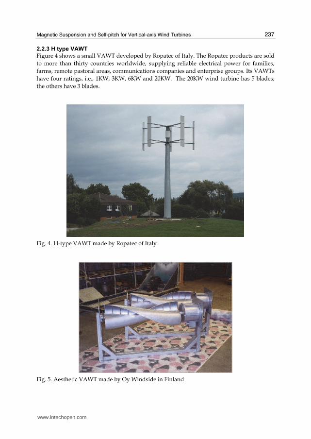
2.2.3 H type VAWT
Figure 4 shows a small VAWT developed by Ropatec of Italy. The Ropatec products are sold
to more than thirty countries worldwide, supplying reliable electrical power for families,
farms, remote pastoral areas, communications companies and enterprise groups. Its VAWTs
have four ratings, i.e., 1KW, 3KW, 6KW and 20KW. The 20KW wind turbine has 5 blades;
the others have 3 blades.
Fig. 4. H-type VAWT made by Ropatec of Italy
Fig. 5. Aesthetic VAWT made by Oy Windside in Finland
www.intechopen.com
Fundamental and Advanced Topics in Wind Power
238
2.2.4 Aesthetic VAWT
A new type of VAWT as shown in Figure 5 has been developed by Oy Windside in Finland. The wind turbine as a derivative of marine engineering, can be used for charging batteries and provide an environment-friendly image. One of the applications of Oy Windside wind turbines is about “wind art”. The concept is to integrate the wind turbine into art and provide lighting. The aesthetics function and ecological concept are both considered in the turbine design.
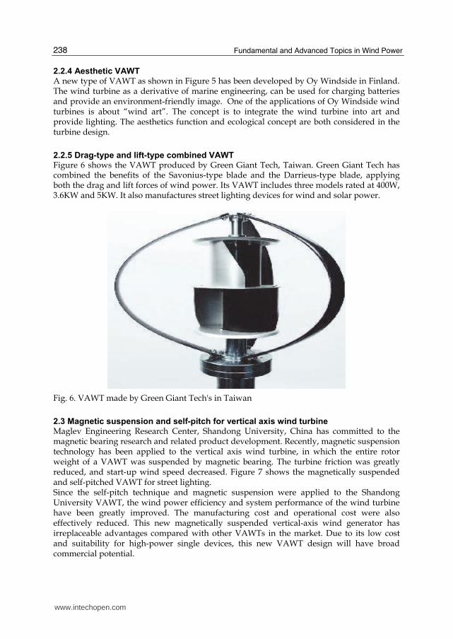
2.2.5 Drag-type and lift-type combined VAWT
Figure 6 shows the VAWT produced by Green Giant Tech, Taiwan. Green Giant Tech has combined the benefits of the Savonius-type blade and the Darrieus-type blade, applying both the drag and lift forces of wind power. Its VAWT includes three models rated at 400W, 3.6KW and 5KW. It also manufactures street lighting devices for wind and solar power.
Fig. 6. VAWT made by Green Giant Tech's in Taiwan
2.3 Magnetic suspension and self-pitch for vertical axis wind turbine
Maglev Engineering Research Center, Shandong University, China has committed to the magnetic bearing research and related product development. Recently, magnetic suspension technology has been applied to the vertical axis wind turbine, in which the entire rotor weight of a VAWT was suspended by magnetic bearing. The turbine friction was greatly reduced, and start-up wind speed decreased. Figure 7 shows the magnetically suspended and self-pitched VAWT for street lighting. Since the self-pitch technique and magnetic suspension were applied to the Shandong University VAWT, the wind power efficiency and system performance of the wind turbine have been greatly improved. The manufacturing cost and operational cost were also effectively reduced. This new magnetically suspended vertical-axis wind generator has irreplaceable advantages compared with other VAWTs in the market. Due to its low cost and suitability for high-power single devices, this new VAWT design will have broad commercial potential.
www.intechopen.com
Magnetic Suspension and Self-pitch for Vertical-axis Wind Turbines
239
Fig. 7. Magnetically suspended and self-pitched VAWT from Maglev Engineering Center, Shandong University
3. Application of magnetic suspension in wind turbine
3.1 Principle and types of magnetic suspension Magnetic suspension means that an object is suspended by magnetic attraction and/or repulsion forces to achieve non-contact support and low-friction in motion. The magnetic suspension as a branch in mechatronics technology, involves disciplines in electromagnetism, power electronics, signal processing, control engineering, statics and dynamics. Therefore, the development of the magnetic suspension technology has been closely related to and relied on the development of these fields of disciplines. Because of no mechanical contact in the magnetic bearing, it has many advantages, including no wear, no contamination, suitable for long-term use in vacuum and corrosive environment, no mechanical friction, low noise, low power loss and no need of lubrication or sealing. Therefore, magnetic suspension technology can be used for high-speed applications to eliminate mechanical problems related to lubrication and power loss. There are many applications of the magnetic suspension technology, including maglev train and magnetic bearing. Many countries have developed different types of maglev trains; Germany, Japan and China are among those having the most mature maglev technology. The fastest speed of the maglev train can reach 500km/h. On the other hand, the magnetic bearing technology has been widely applied in the aerospace industry, medical health field and new energy power. Some magnetic bearings have been tested in space shuttles and rockets in USA and Japan and achieved satisfactory performances. There were magnetic bearings successfully implemented in artificial heart pump developed by University of Virginia and University of Utah. Base on the source of the magnetic field, magnetic bearings can be classified into three kinds as follows: 1. Active Magnetic Bearing (AMB) - The magnetic field is controllable. The control system
detects the position of the rotor and actively controls the suspension of the rotor. The bearing stiffness and damping are electronically tuneable and the load capacity is large.
www.intechopen.com
Fundamental and Advanced Topics in Wind Power
240
The principle of active magnetic suspension is depicted by a simple magnetic suspension system in Figure 8, which shows a displacement sensor, controller and actuator. The actuator includes electromagnets and power amplifiers. Assuming there is a downward perturbation, the position change of the suspended object, such as the rotor in Figure 8, can be detected by the sensor and the displacement signal immediately is transmitted to the controller. The signal will be transformed into a command by the microprocessor of the controller, which in turn produces a change or increase of control current in the electromagnets. The suspended object will be then pulled back up to its original position by the changing magnetic field generated in the electromagnet. Therefore, the rotor will always be kept at a preset position regardless the perturbation is down or up.
Fig. 8. Diagram of active magnetic suspension system
2. Passive Magnetic Bearing (PMB) - As showed in Figure 9, the PMB magnetic field is created using permanent magnets or superconductors. The rotor is suspended by passive magnetic forces. The advantages of PMB are its simple structure, low cost, low power loss, etc., but the load capacity of PMB is small and so is the stiffness.
Fig. 9. Permanent magnetic bearings
3. Hybrid magnetic bearing (HMB) - As showed in figure 10, the mechanical structure of HMB includes electromagnet and permanent magnet (or superconductor); the magnetic force is generated by both the permanent magnet and electromagnet. Its structure complexity, cost and performance are average between AMB and PMB.
www.intechopen.com
Magnetic Suspension and Self-pitch for Vertical-axis Wind Turbines
Based on the functions of magnet bearings, magnetic bearing can be further classified as
axial (thrust) magnetic bearing and radial magnetic bearing.
3.2 Magnetic suspension technology in wind turbine
Permanent magnet bearing has the advantages of low power consumption, no mechanical
contact and suitable for severe adverse environment. In recent years, with the rapid
development of permanent magnet material, the technology of permanent magnetic
suspension has been expanded to wind turbine applications. This has greatly reduced the
cost and stringency of wind power. Specifically, the application of magnetic suspension to
wind turbines has achieved the following advantages:
1. Starting wind speed is reduced by magnetic suspension due to reduced bearing friction
and power output of wind turbine is increased for the same wind speed.
2. Magnetic suspension has largely changed the traditional wind turbine rotor system
design using special rolling-element or oil-film bearings. These traditional bearings
depend on careful lubrication and sealing for long service life, impact resistance, and
high reliability. The magnetic suspension not only reduces the cost of the bearings and
their maintenance, but also reduces the downtime of the wind turbine and therefore,
improves the over-all efficiency of the system.
Magnetic suspension technology applied to wind turbine is an emerging technology; the
development of maglev magnetic wind turbine is just beginning. Although there claimed
many maglev wind turbine products have been developed, relevant published studies are
rare.
Currently, the studies on magnetic suspension of wind turbines have been focused on the
HAWTs. A typical magnetic suspension for an HAWT is to use PMB in radial directions and
a mechanical bearing or a ball in axial direction.
Figure 11 shows a magnetic suspension system of wind turbine with five degrees of
freedom using radial and axial magnetic bearings.
www.intechopen.com
Fundamental and Advanced Topics in Wind Power
242
1 lower backup thrust ring, 2 axial magnetic bearing, 3 radial magnetic bearing, 4 generator, 5 upper backup bearing, 6 lower backup bearing, 7 rotor shaft, 8 radial magnetic bearing stator, 9 shell, 10 upper backup thrust ring, 11 axial magnetic bearing rotor disk, 12 axial magnetic bearing stator, 13 radial magnetic bearing rotor, 14 generator rotor, 15 generator stator
Fig. 11. Magnetic suspension system of vertical axis wind turbine
The thrust (axial) bearing is the most important part of the VAWT magnetic suspension system. It supports the weight of the blades and generator rotor. An implementation of the thrust bearing using permanent magnets is presented in Figure 12(a). A passive radial bearing structure resisting radial disturbance is shown in Figure 12(b).
Fig. 12. Axial (a) and radial (b) magnetic bearing in VAWT
PMBs are normally made of NdFeB (neodymium iron boron) magnets. These magnets are
currently the best choice for magnetic bearings because of its high magnetic energy product
and low cost. Also its process-ability is better than other permanent materials, such as SmCo
alloy. But the temperature stability and erosion resistance are needed to improve for NdFeB
magnets. Inferior to SmCo, typical NdFeB Curie temperature is 312°C and reversible
temperature coefficient of remanence is -0.13/°C. Typical NdFeB working temperature is
below 80°C. For better temperature stability and erosion resistance, the NdFeB magnets
chosen for wind turbines have been manufactured by hot-rolling process. The process yields
good tension strength, and oxidation resistance.
www.intechopen.com
Magnetic Suspension and Self-pitch for Vertical-axis Wind Turbines
243
4. Self-pitch technique in wind turbine
Pitch control is one of the key technologies in wind turbine and its development has progressed from fixed pitch to controllable pitch. The fixed-pitch design has the blades fixed on the arms so that the windward angle will not change with wind speed in operation. The controllable pitch design is to change the blade pitch angle according to the wind speed in order to control the generator output power. Moreover, it is necessary to control blade pitch to lower starting torque during wind turbine start-ups. Comparing with the fixed-pitch wind turbines, the controlled-pitch designs can produce more wind power, because it can vary blade pitch according to variable wind speed. For stable loading control, security and high efficiency, blade-pitch control is employed in most large HAWTs. The pitch-controlled system consists of pitch bearing and pitch gear. When blade pitch adjustment is needed, the control device will drive a small gear through the pitch bearing to achieve the desired the blade angle. Currently on commercial market, the pitch control devices are powered by hydraulic or electrical variable pitch systems. The pitch control is generally achieved by applying variable-speed constant-frequency control. And the main control strategies applied to wind turbines include the classical PD (proportion-integral) control, PID (proportional-integral-derivative) control, fuzzy control, neural networks, and the optimal control theory. In recent years, the development of VAWT was mainly concentrated in the fixed-pitch type, and most of the machines presented in Chapter 2 are of this type. However, the fixed-pitch turbines have low utilization of wind power and poor start-up performance. If VAWT is combined with a pitch-controlled device, the self-starting performance and the wind power utilization will improve because adjusting the blade pitch angle changes the aerodynamic characteristic of the blades. At present, research on the pitch-controlled VAWT has made some success. However, those pitch-controlled devices were complicated and costly. With high power consumption and low reliability in operation, these progresses have not yet lead to inexpensive wind power. Overall, the traditional VAWTs have disadvantages of poor start-up performance, complicated pitch control system, high cost, low utilization of wind power and inability to keep the optimal blade pitch angle all the time in operation. And all these disadvantages severely limit its applications in the wind power field. To overcome these shortcomings, presented in the subsequent section is another kind of self-pitch vertical axis wind turbine with high efficiency and structure simplicity.
4.1 The structure and principle of self-adjusting pitch vertical axis wind turbine
The straight wing VAWT is the lift-type wind turbine. During its rotation, the lift force perpendicular to the blade is constantly changing. When a blade is at positions parallel to the wind direction, the lift on the blade is very small. At positions perpendicular to the wind, the lift would be large. The angle between the incoming air flow velocity at the blade nose and the chord of the blade (connection between blade leading edge and trailing edge) is called the attack angle,
also known as the pitch angle, represented by “”. For the lift-type VAWT, according to aero-foil lift and drag coefficient curves, good aerodynamic performance occurs within a small range of attack angle. Out of this range, the wind machine will be subjected to large aerodynamic drag resulting in lower utilization of wind energy or even the braking effect. Therefore, one can change the blade attack angle so that blades always generate large
www.intechopen.com
Fundamental and Advanced Topics in Wind Power
244
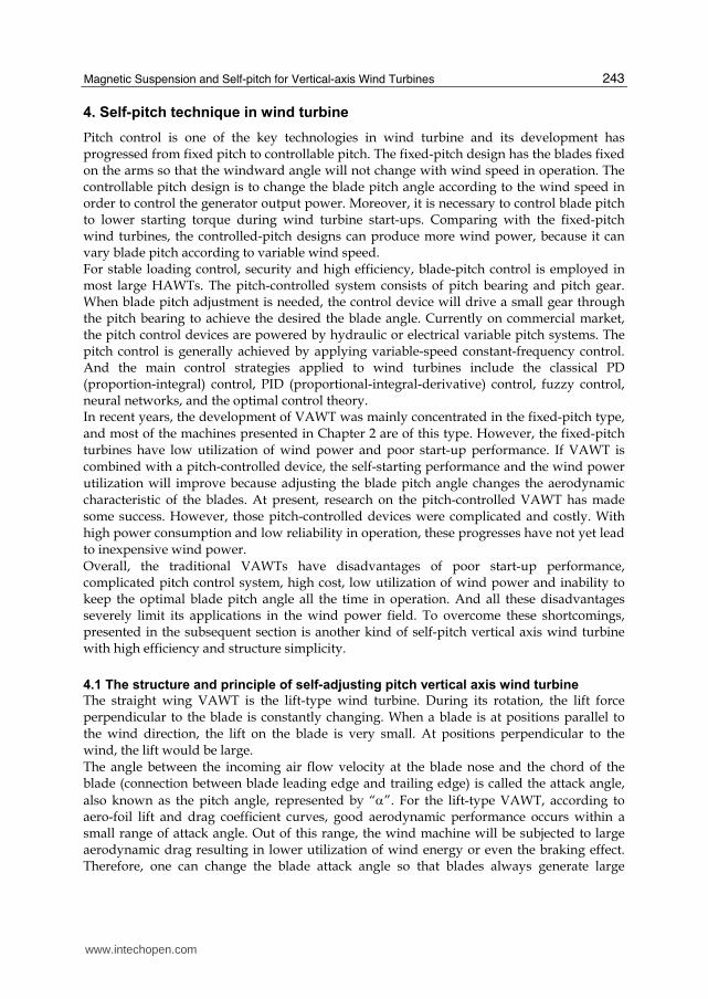
aerodynamic torque; improve the wind energy utilization and the self-starting capability of the wind turbine. The self-adjusting blade pitch mechanism described herein is based on the centrifugal
positioning and the lift adjustment during operation of wind turbine blades. The blade CG
(center of gravity) is at the nose, and it is hinged to the round-arm of the turbine wheel. The
centrifugal force of the blade is balanced by the centripetal force generated by the round-
arm. Since the blade nose and round-arm is on a straight line, the chord would be
perpendicular to the round-arm. The action that the blade maintains itself to be
perpendicular to the round-arm by the centrifugal force is called centrifugal positioning.
When the angle between wind direction and blade is larger than the best pitch angle (see
Figure 13), the lift will pull the blade to a counter-clockwise rotation, and reduce to . The
combined action of the centrifugal position and lift always maintains the attack angle in
the optimum range. The figure shows, the blade’s center of gravity must be located before
the point where the lift applies. Otherwise the self-pitching will not work.
O
F
yF
Fig. 13. The principle of self-adjusting pitch
Thus, by properly-designing the nose CG position and the lift force bearing point on blade,
one can achieve the automatic adjustment of the pitch angle and maintain it in the optimum
range. The working process of a self-pitched VAWT is described as follows.
When the wind turbine is stationary, some blades will automatically adjust in parallel to
wind and some perpendicular to wind; it is essentially a drag-type wind turbine. The blade
parallel to wind direction bears large wind thrust and the blade perpendicular to wind
direction bears small wind drag. The difference between the thrust and drag starts the wind
turbine in low wind speed. At the moment of starting, the turbine blades will automatically
adjust the attack angle and work under lift type mode. When the wind is relative stable, the
blade pitches will be adjusted periodically during each rotation. Those blades in parallel
with the wind will have zero pitch angles and experience no pull or pushing force. Those
blades at any other positions will have pushing force acting on them. The whole process is
automatic without using any devices or driving force. The scheme of self-pitch VAWT is
shown in figure 14.
www.intechopen.com
Magnetic Suspension and Self-pitch for Vertical-axis Wind Turbines
245
Fig. 14. The scheme of self-pitch vertical axis wind turbine
4.2 The design of the blade of self-pitch
The blades of self-pitch VAWT are designed in straight wing shape without bends or
variable cross section; they are easy to manufacture with low-cost. Arm design is based on
aerodynamic principles and triangular vector connections, which reduce the threat of
opposite wind pressure on the blades. Therefore, the new design improves deformation
resistance and reduces blade cost.
The blades of the self-pitch VAWT are uniformly distributed along the circumference. Since
fewer blades may lead to low power output and too many blades may adversely affect the
aerodynamic characteristic, a VAWT with straight wing blades in general have 3 to 6 blades.
In order for self-pitch adjustment, the blade is designed with nose CG located before the
maximum thickness position. This ensures that the lift force acting point is behind or after
the CG. Therefore, the blade pitch angles will be kept in the best range under the centrifugal
force and lift torque.
Furthermore, the rapid development of blade material and unique structure for typhoon
resistance provides a potential opportunity to increase the power capacity of VAWT.
4.3 The experiments of the self-pith vertical axis turbine
In the above two sections, the principle of self-pitch VAWTs has been presented. In this
section, their good performance will be verified through comparative experiments with
other type wind turbines. Experiments process is as follows:
Wind field is produced by 2*3 array wind generators using variable-frequency drive. Wind
speed is controlled in the range of 1~11m/s. A self-pitch VAWT with streamline
symmetrical blades (type A), a fixed-pitch VAWT with streamline symmetrical blades (type
B) and a self-pitch VAWT with arc blades (type C) have been tested. Their start-up
properties and power outputs were measured and compared. The parameters of these tested
wind turbines are listed in table 1.
www.intechopen.com
Fundamental and Advanced Topics in Wind Power
246
Parameters wind turbine A wind turbine B wind turbine C
Pitch type Self-pitch Fixed-pitch Self-pitch
Number of blades
5 5 5
Blade shape
Streamline symmetrical blades
Streamline symmetrical blades
Arc blades
Sizes of blade
120cm(L)20cm(W) 2.5 cm(T)
120cm(L)20cm(W) 2.5 cm(T)
120cm(L)20cm(W)
1.75 cm(T)
Weight of each bade
1.65kg 1.65kg 1.15kg
Diameter of arm rotation
2m 2m 2m
Generator 300W permanent magnet generator
300W permanent magnet generator
300W permanent magnet generator
Table 1. The parameters of wind turbine A, B and C
The wind turbine rotational speed and output power as functions of wind speed were
recorded from the experiments, and they are plotted in Figure 15 and 16, respectively.
Experiment results show that the start-up properties and efficiency of wind utilization were
enhanced in the self-pitch VAWTs due to the implemented self-pitch technology and
optimal design of blades. Magnetic suspended self-pitch VAWT is a new and high-efficiency
wind turbine.
5. Conclusion
In this chapter, the basic principle and main features of a magnetic suspended self-pitch
vertical axis wind turbine have been presented. Compared with the horizontal axis wind
turbine and the traditional vertical axis wind turbine, this new VAWT has the following
advantages:
The magnetic suspension in all degrees of freedom has applied permanent magnets. The bearing friction and mechanical noise are low. The starting torque, thus the starting wind speed is low. As a result, the wind turbine consumes little power and has a high efficiency using wind power.
During rotation, the blades automatically adjust their attack angles to the optimal values and therefore, generate large lifts.
The wind turbine structure is designed based on aerodynamics and triangular vector connection method. As a result, the threat of normal blade pressure was mitigated, and the blade manufacturing cost reduced.
Blades can be made with different sizes as spare parts, which can be used for the same wind turbine but according to local wind power resource needs. This is a unique feature not available for other wind turbines.
In order to lower wind power investment, the power capacity of any single wind turbine should be increased as much as possible. The VAWT presented herein can easily increase the unit power by simply elongating the turbine wheel arms and blades.
This VAWT design has a simple structure and low manufacturing cost. It needs no complicated control mechanism to adjust the blade attack angles. It has a direct-drive permanent magnet generator with no need of gear box or yawing wind direction control.
www.intechopen.com
Fundamental and Advanced Topics in Wind Power
248
The blades automatically adjust attack angles to reduce wind thrust, and therefore, can survive in Typhoon.
This VAWT can start up by itself. In summary, the new vertical axis wind turbines have adopted magnetic bearings and self-pitch blade design. Consequently their utilization rate of wind power is improved, overall efficiency of wind turbine is enhanced, and the production cost as well as maintenance cost is reduced. The magnetically-suspended self-pitch vertical-axis wind turbines have irreplaceable advantages and demonstrated the superiority of vertical axis wind turbines.
6. References
TIAN Hai-jiao; WANG Tie-long; WANG Ying. Summarize of the development of the vertical-axis wind turbine. In : Applied Energy Technology, Vol.6, pp. 22-27, ISSN 1009-3230.
Steinbuch, M. Dynamic modeling and robust control of a wind energy conversion system. Ph., D. Thesis, University of Delft, Holland 1989.
H. Camblong. Digital robust control of a variable speed pitch regulated wind turbine for above rated wind speeds. In: Control Engineering Practice, Vol.16, No. 8, pp. 946-958, ISSN 0967-0661.
Ahmet Serdar Yilmaz a, Zafer Ozer. Pitch angle control in wind turbines above the rated windspeed by multi-layer perception and radial basis function neural networks. In : Expert Systems with Applications, Vol. 36, pp. 9767-9775, ISSN 0957-4174.
YANG Hui-jie, YANG Wen-tong. The new development of foreign small vertical axis wind generators. In : Power Demand Side Management, Vol. 9, No. 2, pp. 68-70, ISSN 1009-1831.
QU Jian-jun, XU Ming-wei, LI Zhong-jie, ZHI Chao. Renewable Energy Resources, Vol. 28, No. 1, pp. 101-104.
Shuqin Liu, Zhongguo Bian, Deguang Li, Wen Zhao.A Magnetic Suspended Self-pitch Vertical Axis Wind Generator. Proceedings of Power and Energy Engineering Conference (APPEEC), ISBN: 978-1-4244-4812-8, chengdu, March 2010.
HU Ye-faa; XU Kai-guob, et. al. Analysis and Design of Magnetic Bearings Used in Magnetic Suspending Wind Power Generator. In : Bearing, Vol. 7, pp. 6-10, ISSN 1000-3762.
Global Wind Technology INC, Watkins Philip G. Omni-Directional Wind Turbine Electric Generation System. America, WO2005108785,2005.
www.intechopen.com
Fundamental and Advanced Topics in Wind PowerEdited by Dr. Rupp Carriveau
ISBN 978-953-307-508-2Hard cover, 422 pagesPublisher InTechPublished online 20, June, 2011Published in print edition June, 2011
InTech ChinaUnit 405, Office Block, Hotel Equatorial Shanghai No.65, Yan An Road (West), Shanghai, 200040, China
Phone: +86-21-62489820 Fax: +86-21-62489821
As the fastest growing source of energy in the world, wind has a very important role to play in the globalenergy mix. This text covers a spectrum of leading edge topics critical to the rapidly evolving wind powerindustry. The reader is introduced to the fundamentals of wind energy aerodynamics; then essential structural,mechanical, and electrical subjects are discussed. The book is composed of three sections that include theAerodynamics and Environmental Loading of Wind Turbines, Structural and Electromechanical Elements ofWind Power Conversion, and Wind Turbine Control and System Integration. In addition to the fundamentalrudiments illustrated, the reader will be exposed to specialized applied and advanced topics including magneticsuspension bearing systems, structural health monitoring, and the optimized integration of wind power intomicro and smart grids.
How to referenceIn order to correctly reference this scholarly work, feel free to copy and paste the following:
Liu Shuqin (2011). Magnetic Suspension and Self-pitch for Vertical-axis Wind Turbines, Fundamental andAdvanced Topics in Wind Power, Dr. Rupp Carriveau (Ed.), ISBN: 978-953-307-508-2, InTech, Available from:http://www.intechopen.com/books/fundamental-and-advanced-topics-in-wind-power/magnetic-suspension-and-self-pitch-for-vertical-axis-wind-turbines