18
www.lanzar.com 10-Channel Active Electronic Crossover Network with Subwoofer Level Control user’s manual OptiX-10 OptiX-10
| Date post: | 14-May-2018 |
| Category: |
Documents |
| Upload: | truongtruc |
| View: | 220 times |
| Download: | 1 times |

www.lanzar.com 10-Channel ActiveElectronic Crossover Networkwith Subwoofer Level Control
u s e r ’ s m a n u a l
OptiX-10OptiX-10
Congratulations on your purchase of a new Lanzar Opti signal processor. Opti mobile electronics are some of the most advanced
car audio products available. These quality audio products are designed and engineered to afford you years of uncompromising
musical service. Lanzar has utilized the latest electronic technologies in order to deliver a superb listening experience.
The X10 Active Crossover offers the listener the ability to enjoy the finest in mobile audio. The X10 unleashes the effortless,
natural and open quality of the real performance. Car audio systems which utilize passive crossovers feed the music through
chokes and capacitors, which creates a “bottleneck” through which the music must pass. Portions of the program material may
pass through at different speeds, creating distortion – some of the music doesn’t make it through at all!
With the Lanzar Opti X10 you’ll hear all the dynamics in the bass, and still hear delicacies like fingers sliding across guitar
strings. The X10 also allows the user to group amplifiers and separate speakers in discrete assemblages so they play as one
cohesive unit, in harmony with each other. The X10 becomes the music conductor in the system, balancing volume, assigning
the proper part of the music to a specific instrument, delaying some sounds so they reach your ear just as the rest of the music
does, with the sole purpose of creating the illusion that there is only the music.
I N T R O D U C T I O N . . .
general features
precautions
features and specifications
system wiring
mounting and installation
noise check and system adjustment
troubleshooting
2
3
4-6
7-11
12-13
14
15
t a b l e o f c o n t e n t s

10 Crossover ChannelsBlue Light Illumination4 Channel InputsSignal Pass-through for Additional ProcessorsRemote Bass Level ControlHigh Channels: Separate Front and Rear Frequency and Gain ControlsMid Channels: Separate Front and Rear Frequency and Gain ControlsSub Channels: Frequency and Gain ControlSelectable Q Settings for Front and Rear ChannelsSubwoofer Stereo/Mono SwitchHigh Channel and Subwoofer Phase InvertersBass Boost Frequency and Level ControlGold-Plated Connectors and Terminals
2
g e n e r a l f e a t u r e s

3
P r e c a u t i o n s
To prevent short circuits, be sure to disconnect the negative battery ground lead before wiring the system up.
When you finish the installation, be sure to make one more check to be sure everything is done correctly.
Reinstate all car parts that were removed.
Reconnect the negative battery ground lead.

4
f e a t u r e s a n d s p e c i f i c a t i o n s
5
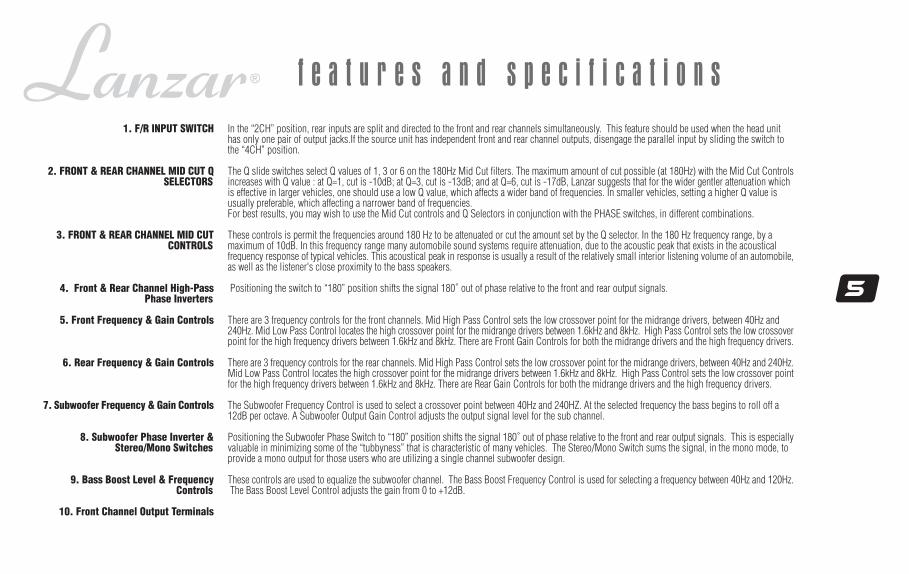
f e a t u r e s a n d s p e c i f i c a t i o n s1. F/R INPUT SWITCH
2. FRONT & REAR CHANNEL MID CUT QSELECTORS
3. FRONT & REAR CHANNEL MID CUTCONTROLS
4. Front & Rear Channel High-PassPhase Inverters
5. Front Frequency & Gain Controls
6. Rear Frequency & Gain Controls
7. Subwoofer Frequency & Gain Controls
8. Subwoofer Phase Inverter &Stereo/Mono Switches
9. Bass Boost Level & FrequencyControls
10. Front Channel Output Terminals
In the “2CH” position, rear inputs are split and directed to the front and rear channels simultaneously. This feature should be used when the head unithas only one pair of output jacks.If the source unit has independent front and rear channel outputs, disengage the parallel input by sliding the switch tothe “4CH” position.
The Q slide switches select Q values of 1, 3 or 6 on the 180Hz Mid Cut filters. The maximum amount of cut possible (at 180Hz) with the Mid Cut Controlsincreases with Q value : at Q=1, cut is -10dB; at Q=3, cut is -13dB; and at Q=6, cut is -17dB, Lanzar suggests that for the wider gentler attenuation whichis effective in larger vehicles, one should use a low Q value, which affects a wider band of frequencies. In smaller vehicles, setting a higher Q value isusually preferable, which affecting a narrower band of frequencies.For best results, you may wish to use the Mid Cut controls and Q Selectors in conjunction with the PHASE switches, in different combinations.
These controls is permit the frequencies around 180 Hz to be attenuated or cut the amount set by the Q selector. In the 180 Hz frequency range, by amaximum of 10dB. In this frequency range many automobile sound systems require attenuation, due to the acoustic peak that exists in the acousticalfrequency response of typical vehicles. This acoustical peak in response is usually a result of the relatively small interior listening volume of an automobile,as well as the listener's close proximity to the bass speakers.
Positioning the switch to “180” position shifts the signal 180˚ out of phase relative to the front and rear output signals.
There are 3 frequency controls for the front channels. Mid High Pass Control sets the low crossover point for the midrange drivers, between 40Hz and240Hz. Mid Low Pass Control locates the high crossover point for the midrange drivers between 1.6kHz and 8kHz. High Pass Control sets the low crossoverpoint for the high frequency drivers between 1.6kHz and 8kHz. There are Front Gain Controls for both the midrange drivers and the high frequency drivers.
There are 3 frequency controls for the rear channels. Mid High Pass Control sets the low crossover point for the midrange drivers, between 40Hz and 240Hz.Mid Low Pass Control locates the high crossover point for the midrange drivers between 1.6kHz and 8kHz. High Pass Control sets the low crossover pointfor the high frequency drivers between 1.6kHz and 8kHz. There are Rear Gain Controls for both the midrange drivers and the high frequency drivers.
The Subwoofer Frequency Control is used to select a crossover point between 40Hz and 240HZ. At the selected frequency the bass begins to roll off a12dB per octave. A Subwoofer Output Gain Control adjusts the output signal level for the sub channel.
Positioning the Subwoofer Phase Switch to “180” position shifts the signal 180˚ out of phase relative to the front and rear output signals. This is especiallyvaluable in minimizing some of the “tubbyness” that is characteristic of many vehicles. The Stereo/Mono Switch sums the signal, in the mono mode, toprovide a mono output for those users who are utilizing a single channel subwoofer design.
These controls are used to equalize the subwoofer channel. The Bass Boost Frequency Control is used for selecting a frequency between 40Hz and 120Hz. The Bass Boost Level Control adjusts the gain from 0 to +12dB.
6
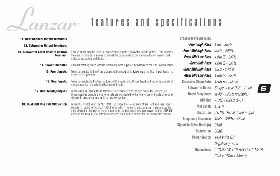
f e a t u r e s a n d s p e c i f i c a t i o n sCrossover Frequencies
-Front High-Pass-Front Mid High-Pass-Front Mid Low-Pass
-Rear High-Pass-Rear Mid High-Pass-Rear Mid Low-Pass
Crossover Slope RateSubwoofer BoostBoost Frequency
Mid CutMid Cut Q:Distortion
Frequency ResponseSignal-to-Noise Ratio (A)
SeparationPower Source
Dimensions
1.6K - 8KHz
40Hz - 240Hz
1.6KHZ - 8KHz
1.6KHZ - 8KHz
40Hz - 240Hz
1.6KHZ - 8KHz
12dB per octave
Single octave 0dB - 12 dB
at 40 - 120Hz (variable)
-10dB (180Hz Q=1)
1, 3, 6
0.01% THD at 1 volt output
10Hz - 30KHz ±3 dB
95dB
60dB
14.4 Volts DC
Negative ground
9-21/32”W x 10-5/8”D x 1-1/2”H
(245 x 270m x 38mm)
11. Rear Channel Output Terminals
12. Subwoofer Output Terminals
13. Subwoofer Level Remote ControlTerminal
14. Power Indicator
15. Front Inputs
16. Rear Inputs
17. Dual Inputs/Outputs
18. Dual SUB IN & F/R MIX Switch
This terminal may be used to connect the Remote Subwoofer Level Control. This enablesthe user to have easy access to adjust the bass levels to compensate for increased roadnoise or recording variations.
This indicator lights up when the internal power supply is activated and the unit is operational.
To be connected to the Front outputs of the head unit. Make sure the Dual Input Switch isin the “4CH” position.
To be connected to the Rear outputs of the head unit. If your head unit has only one set ofoutputs connect them to the Rear set of inputs.
When used as inputs, these terminals are connected to the sub out of the source unit.When used as outputs these terminals are connected to the Rear channel inputs of anotherelectronic crossover in a multi-crossover system.
When this switch is in the “F/R MIX” position, the stereo sum of the front and rear inputsignals is routed to the Dual In/Out terminals. This summed signal can then be used bythe subwoofer channel or become output to another electronic crossover. In the “SUB IN”position the Dual In/Out terminals become the input terminals for the subwoofer channel.
7
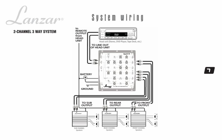
S y s t e m w i r i n g2-CHANNEL 3 WAY SYSTEM
REAR CHANNELSpeakers
FRONT CHANNELSpeakers
Head unit (Stereo, DVD Player, Tape Deck, etc.)
TO REAROUTPUT
TO SUBOUTPUT
toREMOTEOUTPUTfromHEADUNIT
BATTERY
GROUND
TO LINE OUTOF HEAD UNIT
TO FRONTOUTPUT
SUB CHANNELSpeakers
8
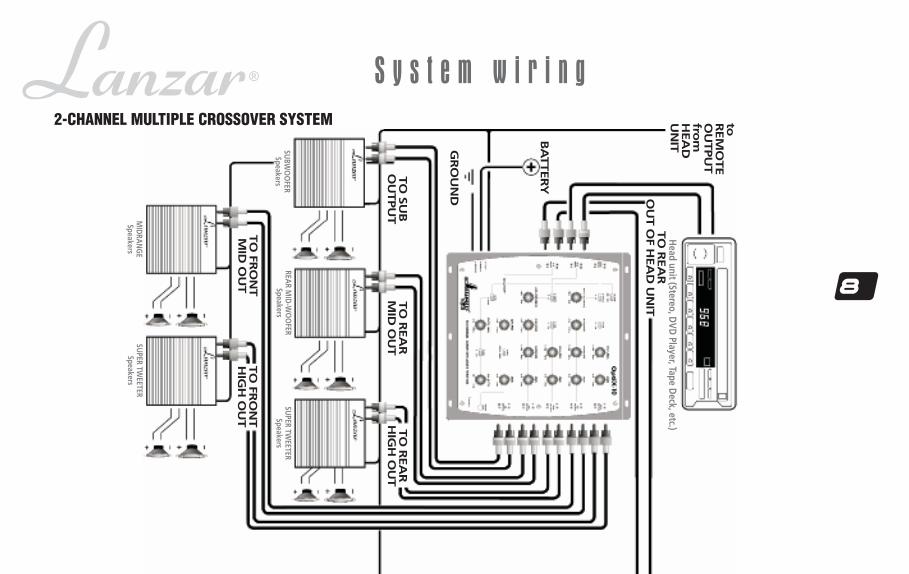
S y s t e m w i r i n g2-CHANNEL MULTIPLE CROSSOVER SYSTEM
TO
REA
RM
ID O
UT
TO
SU
BO
UTPU
T
Head unit (Stereo, D
VD Player, Tape D
eck, etc.)
SUBW
OO
FERSpeakers
REAR M
ID-W
OO
FERSpeakers
TO
FRO
NT
MID
OU
T
TO
REA
RH
IGH
OU
T
TO
FRO
NT
HIG
H O
UT
GR
OU
ND
BA
TTERY
TO
REA
RO
UT O
F HEA
D U
NIT
toREM
OTE
OU
TPU
Tfro
mH
EA
DU
NIT
SUPER TW
EETERSpeakers
MID
RAN
GE
Speakers
SUPER TW
EETERSpeakers

9
TO
SU
BO
UTPU
T
TWEETER
Speakers
SUBW
OO
FERSpeakers
TO
FRO
NT
MID
OU
T
TO
REA
RH
IGH
OU
T
TO
FRO
NT
HIG
H O
UT
GR
OU
ND
BA
TTERY
MID
-WO
OFER
Speakers
WO
OFER
SpeakersU
PPER MID
RAN
GE
Speakers
(to R
EMO
TE OU
TPUT
from
HEA
D U
NIT)
10
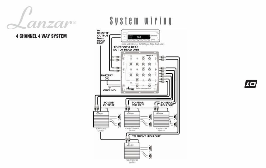
S y s t e m w i r i n g
BATTERY
TO FRONT HIGH OUT
4 CHANNEL 4 WAY SYSTEM
TO REARMID OUT
TO SUBOUTPUT
toREMOTEOUTPUTfromHEADUNIT
GROUND
SUBWOOFERSpeakers
FRONT TWEETERSpeakers
REAR MID-WOOFERSpeakers
TO REARHIGH OUT
TO FRONT & REAROUT OF HEAD UNIT
REAR TWEETERSpeakers

11
S y s t e m w i r i n g
6-CHANNEL 5-WAY SYSTEM
FRONT TWEETERSpeakers
TO REARMID OUT
TO SUBOUTPUT
Head unit (Stereo, DVD Player, Tape Deck, etc.)
toREMOTEOUTPUTfromHEADUNIT
SUBWOOFERSpeakers
FRONT TWEETERSpeakers
REAR MID-WOOFERSpeakers
TO FRONTMID OUT
FRONT MID-WOOFERSpeakers
TO REARHIGH OUT
TO FRONTHIGH OUT
GROUND
BATTERY
TO FRONT, REAR &SUB OUT OF HEAD UNIT
REAR TWEETERSpeakers
12
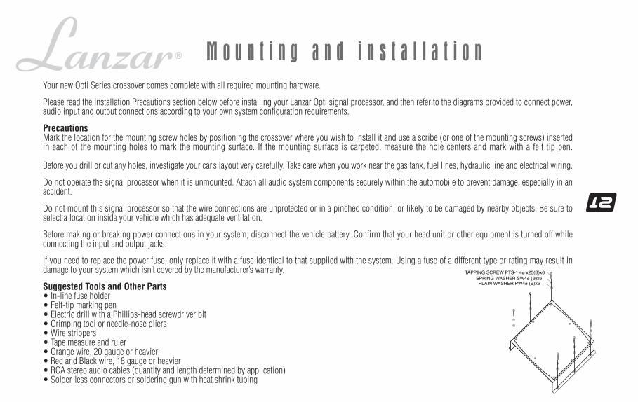
M o u n t i n g a n d i n s t a l l a t i o nYour new Opti Series crossover comes complete with all required mounting hardware.
Please read the Installation Precautions section below before installing your Lanzar Opti signal processor, and then refer to the diagrams provided to connect power,audio input and output connections according to your own system configuration requirements.
PrecautionsMark the location for the mounting screw holes by positioning the crossover where you wish to install it and use a scribe (or one of the mounting screws) insertedin each of the mounting holes to mark the mounting surface. If the mounting surface is carpeted, measure the hole centers and mark with a felt tip pen.
Before you drill or cut any holes, investigate your car’s layout very carefully. Take care when you work near the gas tank, fuel lines, hydraulic line and electrical wiring.
Do not operate the signal processor when it is unmounted. Attach all audio system components securely within the automobile to prevent damage, especially in anaccident.
Do not mount this signal processor so that the wire connections are unprotected or in a pinched condition, or likely to be damaged by nearby objects. Be sure toselect a location inside your vehicle which has adequate ventilation.
Before making or breaking power connections in your system, disconnect the vehicle battery. Confirm that your head unit or other equipment is turned off whileconnecting the input and output jacks.
If you need to replace the power fuse, only replace it with a fuse identical to that supplied with the system. Using a fuse of a different type or rating may result indamage to your system which isn’t covered by the manufacturer’s warranty.
Suggested Tools and Other Parts• In-line fuse holder• Felt-tip marking pen• Electric drill with a Phillips-head screwdriver bit• Crimping tool or needle-nose pliers• Wire strippers• Tape measure and ruler• Orange wire, 20 gauge or heavier• Red and Black wire, 18 gauge or heavier• RCA stereo audio cables (quantity and length determined by application)• Solder-less connectors or soldering gun with heat shrink tubing
13
M o u n t i n g a n d i n s t a l l a t i o n
• Solder-less connectors or soldering gun with heat shrink tubing
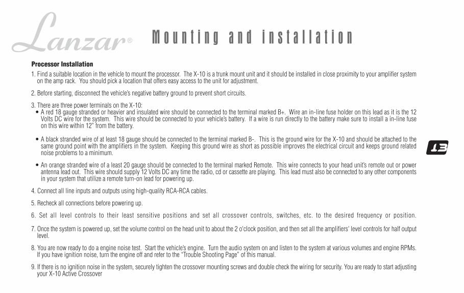
1. Find a suitable location in the vehicle to mount the processor. The X-10 is a trunk mount unit and it should be installed in close proximity to your amplifier systemon the amp rack. You should pick a location that offers easy access to the unit for adjustment.
2. Before starting, disconnect the vehicle’s negative battery ground to prevent short circuits.
3. There are three power terminals on the X-10:• A red 18 gauge stranded or heavier and insulated wire should be connected to the terminal marked B+. Wire an in-line fuse holder on this lead as it is the 12
Volts DC wire for the system. This wire should be connected to your vehicle’s battery. If a wire is run directly to the battery make sure to install a in-line fuseon this wire within 12” from the battery.
• A black stranded wire of at least 18 gauge should be connected to the terminal marked B-. This is the ground wire for the X-10 and should be attached to thesame ground point with the amplifiers in the system. Keeping this ground wire as short as possible improves the electrical circuit and keeps ground relatednoise problems to a minimum.
• An orange stranded wire of a least 20 gauge should be connected to the terminal marked Remote. This wire connects to your head unit’s remote out or powerantenna lead out. This wire should supply 12 Volts DC any time the radio, cd or cassette are playing. This lead must also be connected to any other componentsin your system that utilize a remote turn-on lead for powering up.
4. Connect all line inputs and outputs using high-quality RCA-RCA cables.
5. Recheck all connections before powering up.
6. Set all level controls to their least sensitive positions and set all crossover controls, switches, etc. to the desired frequency or position.
7. Once the system is powered up, set the volume control on the head unit to about the 2 o'clock position, and then set all the amplifiers' level controls for half outputlevel.
8. You are now ready to do a engine noise test. Start the vehicle’s engine. Turn the audio system on and listen to the system at various volumes and engine RPMs.If you have ignition noise, turn the engine off and refer to the “Trouble Shooting Page” of this manual.
9. If there is no ignition noise in the system, securely tighten the crossover mounting screws and double check the wiring for security. You are ready to start adjustingyour X-10 Active Crossover
Processor Installation
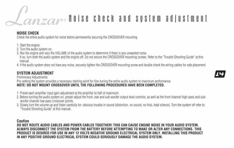
NOISE CHECKCheck the entire audio system for noise before permanently securing the CROSSOVER mounting
1. Start the engine.2. Turn the audio system on.3. Rev the engine and vary the VOLUME of the audio system to determine if there is any unwanted noise.
If so, turn both the audio system and the engine off. Do not secure the CROSSOVER mounting screws. Refer to the "Trouble Shooting Guide" at thismanual.
4. If the audio system does not have any noise, securely tighten the CROSSOVER mounting screw and double check the wiring cables for safe placement.
SYSTEM ADJUSTMENTPreliminary AdjustmentsPre-setting the system provides a necessary starting point for fine-tuning the entire audio system to maximum performance.NOTE: DO NOT MOUNT CROSSOVER UNTIL THE FOLLOWING PROCEDURES HAVE BEEN COMPLETED.
1. Preset each amplifier input gain adjustment at the amplifier to half of maximum.2. Before turning the audio system on, preset-adjust the front, rear and sub-woofer output level controls, as well as the front channel high-pass and sub-
woofer channel low-pass crossover points.3. Slowly turn the volume up and listen carefully for: obvious trouble in sound (distortion, no sound, no hiss, total silence). Turn the system off refer to
"Trouble Shooting Guide" at this manual.
CautionDO NOT ROUTE AUDIO CABLES AND POWER CABLES TOGETHER! THIS CAN CAUSE ENGINE NOISE IN YOUR AUDIO SYSTEM.ALWAYS DISCONNECT THE SYSTEM FROM THE BATTERY BEFORE ATTEMPTING TO MAKE OR ALTER ANY CONNECTIONS. THISPRODUCT IS DESIRED FOR USE IN ANY 12 VOLTS NEGATIVE GROUND ELECTRICAL SYSTEM ONLY. INSTALLING THIS PRODUCTIN ANY POSITIVE GROUND ELECTRICAL SYSTEM COULD SERIOUSLY DAMAGE THE AUDIO SYSTEM.
14
N o i s e c h e c k a n d s y s t e m a d j u s t m e n t
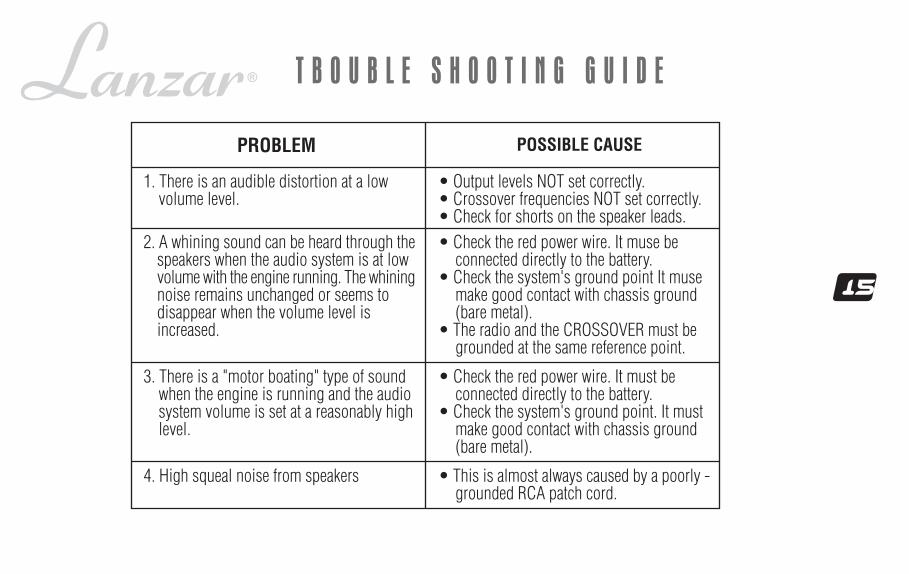
1. There is an audible distortion at a lowvolume level.
PROBLEM POSSIBLE CAUSE
• Output levels NOT set correctly.• Crossover frequencies NOT set correctly.• Check for shorts on the speaker leads.
2. A whining sound can be heard through thespeakers when the audio system is at lowvolume with the engine running. The whiningnoise remains unchanged or seems todisappear when the volume level isincreased.
3. There is a "motor boating" type of soundwhen the engine is running and the audiosystem volume is set at a reasonably highlevel.
• Check the red power wire. It muse beconnected directly to the battery.
• Check the system's ground point It musemake good contact with chassis ground(bare metal).
• The radio and the CROSSOVER must begrounded at the same reference point.
• Check the red power wire. It must beconnected directly to the battery.
• Check the system's ground point. It mustmake good contact with chassis ground(bare metal).
15
T B O U B L E S H O O T I N G G U I D E
4. High squeal noise from speakers • This is almost always caused by a poorly -grounded RCA patch cord.
All Lanzar Signal Processors are carefully constructed and thoroughly testedbefore shipment. Units purchased in the USA are warranted to be free of defectsin material and workmanship for three (3) years from the date of purchase. Thiswarranty is limited to the original retail purchaser of the Signal Processor.
Should the unit fail due to a factory defect in material or workmanship, your unitwill be repaired or replaced at the sole discretion of Lanzar.
To obtain warranty service, you must first call our Consumer Return Hotlinenumber at (718) 236-6948 to obtain a Return Authorization (RA) number. ThisRA Number must appear on the outside of your package and on all paperworkrelating to your return.
When returning the unit to us for warranty service, it must be carefully packedand shipped prepaid to:
You must also include the following items with your return:• A copy of your sales receipt or other proof of purchase• A brief letter indicating the problem you are experiencing with the
product• Include in your letter your return address, daytime phone number
and RA Number• Also include a check or money order for $20.00 for return shipping,
handling and insurance, or provide your VISA/MasterCard numberwith expiration date.
Our obligation under this warranty is limited to the repair or replacementof the defective unit when it is returned to us prepaid. This warranty willbe considered void if the unit was tampered with, improperly serviced,or subject to misuse, neglect or accidental damage.
All implied warranties of merchantability and fitness for a particularpurpose are limited in duration to the length of the warranty. Lanzarexpressly disclaims any liability for incidental or consequential damagescaused by product defects. This warranty does not cover any expenseincurred in the removal and/or reinstallation of the Signal Processor.Lanzar’s total liability will not exceed the purchase price of the SignalProcessor.
Some states do not allow the exclusion or limitation of incidental orconsequential damages, or limitations on how long an implied warrantylasts, so the above limitations and exclusions may not apply to you.This warranty gives you specific legal rights, and you may also haveother rights which vary from state to state.
R.A. # ______________Lanzar Service Center1600 63rd StreetBrooklyn, NY 11204
l i m i t e d w a r r a n t y p o l i c y
w w w . l a n z a r . c o m
C r o s s o v e r


