INSTALLATION INSTRUCTIONS DIGITAL/BARGRAPH SETPOINT GAUGE www.altronicinc.com FORM DSG-1682DUPS II 6-09 www.altronicinc.com 1 1.0 DESCRIPTION 1.1 The Altronic DSG-1682DUPS Digital Bargraph Setpoint Gauge is a two-channel electronic instrument which can be used in the follow- ing modes of operation: ▪ PID CONTROLLER ▪ PID CONTROLLER WITH MAPPING ▪ 4-20mA PROPORTIONAL TO CHANNEL 1 ▪ 4-20mA PROPORTIONAL TO THE DIFFERENTIAL It is designed to monitor pressures, temperatures, vi- bration, and other media using industry-standard transducers. Pressure is measured using stan- dard pressure transducers in the range of 0 to 5 volt, .5 to 4.5 volt, or 4 to 20mA. Temperature is measured using industry standard type J or K thermocouples or amplified temperature transducers. Vibration is measured using standard vibration transmitter/ transducers. Although the gauge is designed for monitor- ing pressure, temperature, or vibration, virtu- ally any transducer in the range of 0 to 5Vdc can be used. Input from current transducers in the range of 0 to 25mA is possible using an exter- nal 200 ohm resistor. Applications using 4-20mA would typically use a 250 ohm resistor. The gauge uses a microcontroller to process the input signal and a nonvolatile memory to store the gauge setup and the setpoint values. A backlit, 128 x 64 character/graphic LCD display is used to display the numeric value, engineering units, the monitored point label, state of the output switch output switch, 4-20mA output, and a bargraph. A front-mounted keypad serves as the user interface. DEVIATION FROM THESE INSTRUCTIONS MAY LEAD TO IMPROPER OPERATION OF THE MACHINE WHICH COULD CAUSE PERSONAL INJURY TO OPERATORS OR OTHER NEARBY PERSONNEL. WARNING: CAUTION: THE DSG-1682DUPS DIGITAL BARGRAPH SETPOINT GAUGE IS SUITABLE FOR USE IN CLASS I, DIVISION 2, GROUPS C & D HAZARDOUS LOCATIONS WHEN INSTALLED IN ACCORDANCE WITH THESE INSTRUCTIONS. THE SENSOR INPUT LEADS CONNECTED TO THIS DEVICE OPERATE AT A LOW VOLTAGE AND POWER LEVEL AND MUST NOT CONTACT ANY EXTERNAL VOLTAGE SOURCE. DAMAGE TO THE SYSTEM WILL RESULT FROM CONNECTION BETWEEN THE INPUT SENSOR LEADS AND THE IGNITION SYSTEM OR ANY AC OR DC POWER SOURCE ABOVE 36 VDC.
1.0 DESCRIPTION 1.1 The Altronic DSG-1682DUPS Digital Bargraph Setpoint Gauge is a
two-channel electronic instrument which can be used in the follow-ing modes of operation:
▪ PID CONTROLLER ▪ PID CONTROLLER WITH MAPPING ▪ 4-20mA PROPORTIONAL TO CHANNEL 1 ▪ 4-20mA PROPORTIONAL TO THE DIFFERENTIAL
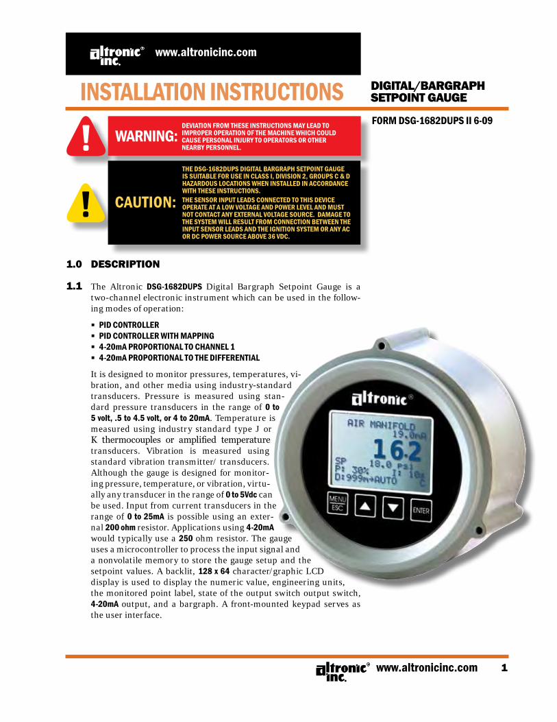
It is designed to monitor pressures, temperatures, vi-bration, and other media using industry-standard transducers. Pressure is measured using stan-dard pressure transducers in the range of 0 to 5 volt, .5 to 4.5 volt, or 4 to 20mA. Temperature is measured using industry standard type J or K thermocouples or amplified temperature transducers. Vibration is measured using standard vibration transmitter/ transducers. Although the gauge is designed for monitor-ing pressure, temperature, or vibration, virtu-ally any transducer in the range of 0 to 5Vdc can be used. Input from current transducers in the range of 0 to 25mA is possible using an exter-nal 200 ohm resistor. Applications using 4-20mA would typically use a 250 ohm resistor. The gauge uses a microcontroller to process the input signal and a nonvolatile memory to store the gauge setup and the setpoint values. A backlit, 128 x 64 character/graphic LCD display is used to display the numeric value, engineering units, the monitored point label, state of the output switch output switch, 4-20mA output, and a bargraph. A front-mounted keypad serves as the user interface.
DEVIATION FROM THESE INSTRUCTIONS MAY LEAD TOIMPROPER OPERATION OF THE MACHINE WHICH COULDCAUSE PERSONAL INJURY TO OPERATORS OR OTHERNEARBY PERSONNEL.
WARNING:
CAUTION:
THE DSG-1682DUPS DIGITAL BARGRAPH SETPOINT GAUGE IS SUITABLE FOR USE IN CLASS I, DIVISION 2, GROUPS C & D HAzARDOUS LOCATIONS WHEN INSTALLED IN ACCORDANCE WITH THESE INSTRUCTIONS.THE SENSOR INPUT LEADS CONNECTED TO THIS DEVICE OPERATE AT A LOW VOLTAGE AND POWER LEVEL AND MUST NOT CONTACT ANY ExTERNAL VOLTAGE SOURCE. DAMAGE TO THE SYSTEM WILL RESULT FROM CONNECTION BETWEEN THE INPUT SENSOR LEADS AND THE IGNITION SYSTEM OR ANY AC OR DC POWER SOURCE ABOVE 36 VDC.
FORM DSG-1682DUPS II 6-092
DIGITAL/BARGRAPH SETPOINT GAUGE
1.2 The Altronic DSG-1682DUPS Digital Bargraph Setpoint Gauge is de-signed to be simple to use with features such as pre-set factory set-tings for pressure, temperature, and vibration. An escape key is provided to permit the user to exit any menu function and return to the home screen. The gauge is also very versatile with features such as programmable input range, units, decimal point, and set-point configuration. A security code can be set to restrict changes to either the configuration, setpoint values, calibration values, and/or communication parameters. In addition, each channel displays a bargraph that can be programmed for increasing bars, a single moving bar between two selected points, a single moving bar be-tween the setpoints, or an increasing bar between setpoints. A pro-grammable software display filter is also incorporated to stabilize readings where the input signal is fluctuating. Configuration can be performed using the front panel keypad.
1.3 RS-485 serial communication allows data and fault status to be com-
municated to other devices via ModBus RTU protocol. This allows the gauge to communicate to other instruments, PC’s or PLC’s via the two serial RS-485 communication wires. Standard baud rates are selectable from 9600 to 115200 baud.
1.4 The power requirement is 12 to 36Vdc, 0.25amps max.
1.5 For proper operation, these installation instructions must be ad-hered to strictly.
2.0 TRANSDUCERS
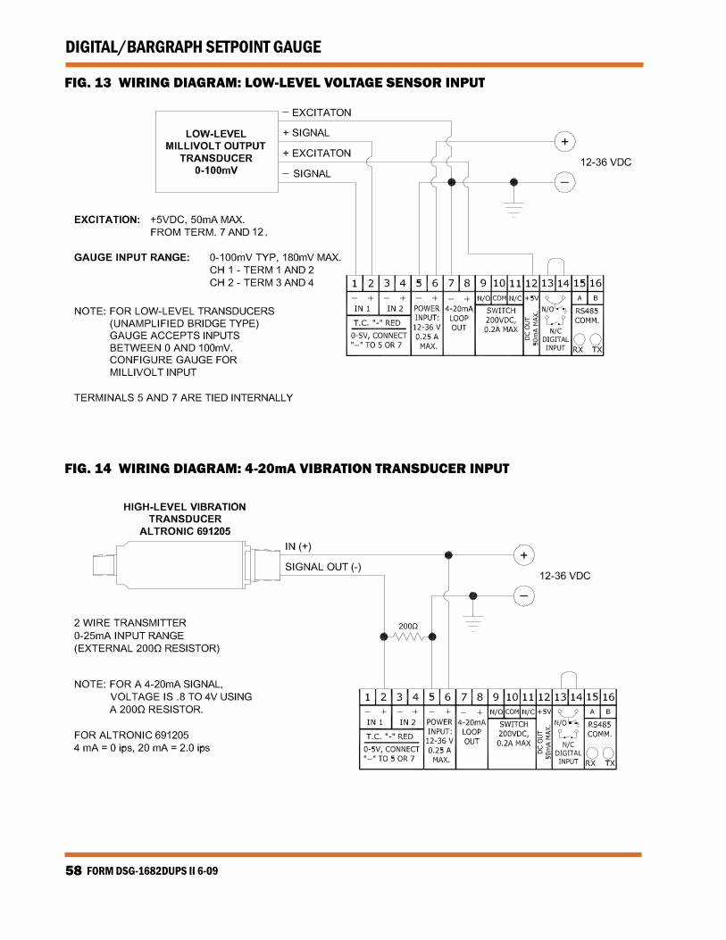
2.1 The DSG-1682DUPS gauge is designed to accept virtually any trans-ducer with an output in the range of 0 to 5Vdc or 0 to 25mA. The gauge is also designed to accept industry standard, grounded or unground-ed, type J or K thermocouples and low level bridge-type sensors from ± 80 millivolts to ± 160 millivolts.
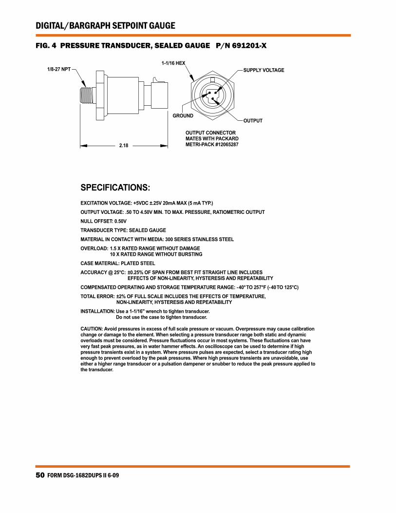
2.2 PRESSURE TRANSDUCERS: ALTRONIC P/N 691201-x AND 691204-x Altronic P/N 691201-x (FIG. 4) is a gauge-type pressure transducer
packaged in a rugged sealed case with a 1/8"-27 N.P.T. pressure port, a stainless steel media cavity, and a Packard Electric “Metri-Pack” connector. The ranges available are 0–15, 50, 100, 300, 500, 1000, 2000, and 5000 psig.
Altronic P/N 691204-x (FIG. 5) is an absolute pressure transducer pack-
aged in a rugged sealed case with a 1/4"-18 N.P.T. pressure port, a stainless steel media cavity, and a Packard Electric “Metri-Pack” con-nector. The ranges available are 0–50, 100, 300, and 500 psia.
The three wires from the transducer are: +5 volt excitation, +0.5 to 4.5
volt output voltage, and minus. These three wires connect directly to the back of the DSG-1682DUPS gauge using cable assembly P/N 693008-x. (FIG. 10)
NOTE: If possible, keep the original shipping container. If future transportation or stor-age of the gauge is necessary, this container will provide the optimum protection.
www.altronicinc.com 3
DIGITAL/BARGRAPH SETPOINT GAUGE
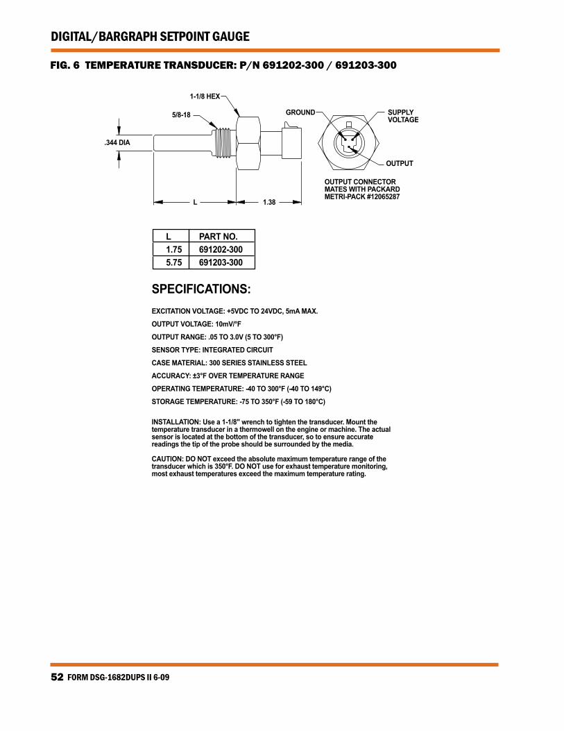
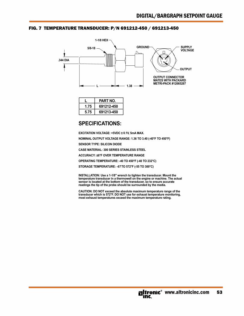
2.3 TEMPERATURE TRANSDUCERS: ALTRONIC P/N 691202-300, 691203-300, 691212-450, 691213-450
Temperature transducers P/N 691202-300 and 691203-300 (FIG. 6) have a temperature measurement range of +5 to 300°F. The transducers are packaged in a sealed, stainless steel housing with a 5/8"-18 UNF threaded body, and a Packard Electric “Metri-Pack” connector. Dur-ing configuration (SEE SECTION 8.5.1) the standard calibration for this sensor is selected as DEG 1.
Temperature transducers P/N 691212-450 and 691213-450 (FIG. 7)
have a temperature range of -40 to +450°F. They are packaged in a sealed, stainless steel housing with a 5/8"-18 UNF threaded body, and a Packard Electric “Metri-Pack” connector. During configuration (SEE SECTION 8.5.1) the standard calibration for this sensor is selected as DEG 2.
The three wires from the transducers are: +5 volt excitation, tempera-
ture output voltage, and minus return. These wires connect directly to the back of the DSG gauge using cable assembly P/N 693008-x. (FIG. 10)
2.4 THERMOCOUPLES: The DSG-1682DUPS gauge is designed to accept in-
dustry standard, grounded or ungrounded, type J or K thermocou-ples. Ungrounded thermocouples are recommended where possible. The instrument can read type J thermocouples between −76°F and +1382°F (−60°C and 750°C) and type K thermocouples between −76°F and +1472°F (−60°C and 800°C).
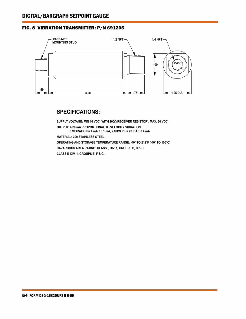
2.5 VIBRATION TRANSMITTER: ALTRONIC P/N 691205 Altronic P/N 691205 (FIG. 8) is a 2-wire seismic vibration transmitter
encapsulated in a stainless steel housing with a 1/4" - 18 N.P.T. mount-ing stud. The output is 0 to 2.0 ips over 4-20mA. The transmitter is a two-wire loop-powered device.
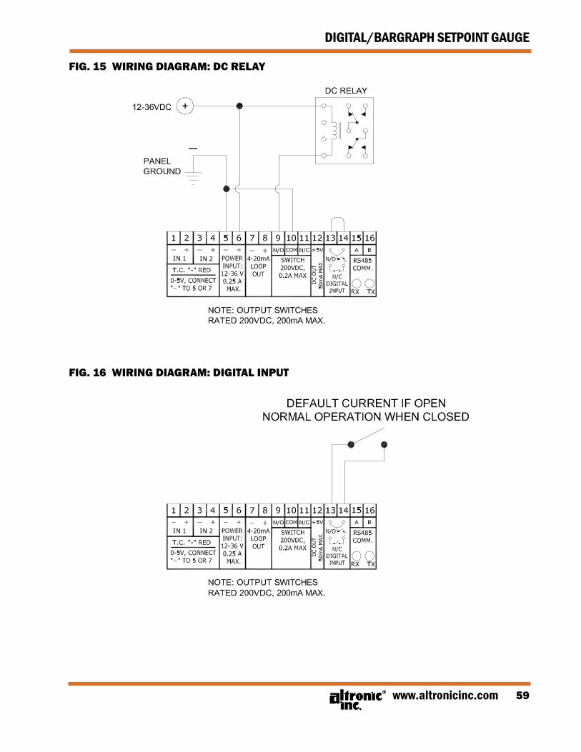
2.6 NORMALLY CLOSED DIGITAL INPUT Wire this digital input for normal operation of the 4-20mA output. If
this input becomes open, the 4-20mA output will change to its pro-grammed state. It will display DEF for the default current output to the left of the current value. This function overrides the normal mode of operation and may be used as a state for shutdown. Leave the jumper in for normal operation.
FORM DSG-1682DUPS II 6-094
DIGITAL/BARGRAPH SETPOINT GAUGE
3.0 MOUNTING (FIG. 1) 3.1 GAUGE: Mount the gauge inside a control panel or to a suitable flat surface
so that the display is at a convenient viewing height. A drilling tem-plate is provided.
3.2 PRESSURE TRANSDUCER: Mount the pressure transducer in the panel or in a manifold or tube
off of the engine. Do not expose the pressure transducer to tempera-tures above 221°F (105°C).
3.3 TEMPERATURE TRANSDUCER: Mount the temperature transducer in a thermowell on the engine
or machine. The actual sensor is located at the bottom of the tube, so to ensure accurate readings the tip of the probe should be sur-rounded by the media.
3.4 VIBRATION TRANSMITTER: Mount the vibration transmitter body to the engine or machine sur-
face. For further mounting instructions see the installation instruc-tions supplied with the transmitter.
NOTE: Avoid mounting the gauge with the LCD display facing direct sunlight. The display temperature range is −4°F to +158°F (−20° C to +70° C).
IMPORTANT: Pressure transducers will withstand overloads as high as 1.5 times rated pressure. If the overload rating is exceeded, failure may occur. Pressure fluctuations occur in most systems; select the trans-ducer with a rating high enough to prevent overload by peak pressures of pulsa-tions. It is recommended that a pressure snubber be used which will reduce the peak pressure applied to the transducer. The life of the transducer will be extended with the use of a snubber or pulsation dampener.
IMPORTANT: Do not exceed the absolute maximum rating of the transducers, 350°F (176°C) for the 691202/203-300 or 572°F (300°C) for the 691212/213-450. Care should be taken to protect the wiring and connectors from contact with hot surfaces.
www.altronicinc.com 5
DIGITAL/BARGRAPH SETPOINT GAUGE
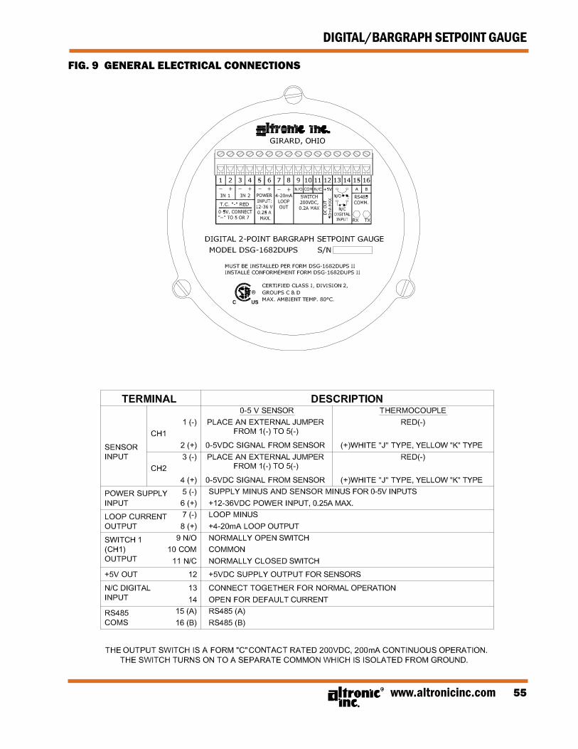
4.0 WIRING (SEE WIRING DIAGRAMS) 4.1 POWER WIRING: (FIG. 9) Connect the power input wires to terminals 5 (−) and 6 (+); power re-
quirement is 12 to 36Vdc, 0.25A max. Connect the minus terminal (−) to panel ground, which should be the same as engine ground. DO NOT ground this device directly to the ignition system common coil ground.
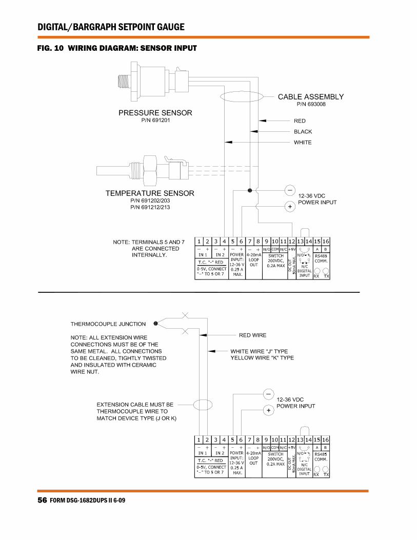
4.2 TRANSDUCER WIRING: (FIG. 10) Select a transducer, either an Altronic pressure, temperature or
vibration transducer or one that outputs a signal in the range of 0 to 5Vdc or 0 to 25mA, and mount as described. Use cable assembly 693008-x or similar to wire transducer to gauge. Take care not to damage the insulation and take precautions against damage from vibration, abrasion or liquids in conduits. Also never run sensor wires in the same conduit as the ignition wiring or other high en-ergy wiring such as AC line power, etc. Keep sensor wires at least 12 inches away from all high voltage wiring.
4.3 THERMOCOUPLES AND THERMOCOUPLE ExTENSION WIRE: (FIG. 10) Grounded or ungrounded type J or K thermocouples may be used.
Use thermocouple extension wire of the same type as the thermo-couple probe to connect the thermocouple to the gauge. Use strand-ed thermocouple wire having a good moisture-resistant insulation such as PVC; for higher ambient temperatures, Teflon or B-fibre in-sulated thermocouple wire is recommended. To ensure an accurate signal is transmitted to the instrument, avoid any added junctions, splices and contact with other metals. Take care not to damage the insulation when installing and take precautions against later dam-age from vibration, abrasion, or liquids in conduits. In addition, it is essential that the following practices be adhered to:
• Never run thermocouple wires in the same conduit with ignition wiring or other high energy wiring such as AC line power.
• Keep secondary wires to spark plugs and other high voltage wiring at least eight inches (200 mm) away from thermocouples and extension wiring.
4.4 OUTPUT SWITCH WIRING: A fault condition will cause the user-programmable output switch to
turn ON/OFF to its common. On the DSG-1682DUPS, the output switch will trip when the input value on either channel (and/or differential if configured) exceeds its setpoint value. This switch is solid state, Form C (N/O and N/C), break-before-make contacts and is isolated from the power supply. The switch is rated at 200V, 200mA and the N/O switch has a unique internal overload current protection circuit. If an overload occurs, the internal circuitry limits current to safe lev-els. When the overload is removed, the relay resumes its normal ON characteristics. This switch can be wired to an Altronic annunciator system or to pilot-duty relays as shown by the WIRING DIAGRAMS.
FORM DSG-1682DUPS II 6-096
DIGITAL/BARGRAPH SETPOINT GAUGE
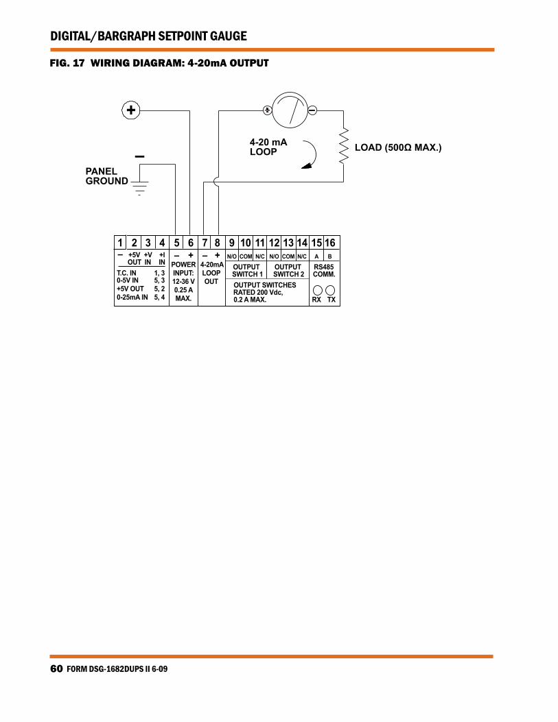
4.5 4-20MA CURRENT LOOP OUTPUT WIRING: Model DSG-1682DUPS has a 4-20mA current loop output available for
the control of valves, actuators and other devices commonly used in process control. The current loop output is accessible through terminals 7 and 8, and is internally limited to 25mA. The output is protected against open and short circuits. A 250 ohm loop resistor can be used over the entire supply voltage range from 12 to 36Vdc. The maximum load resistance that can be tolerated in the loop is deter-mined by the supply voltage. When using the maximum rated loop resistor of 500 ohms with a desired full-scale loop output of 20mA, the supply voltage must be between 15 and 36Vdc. At 12Vdc supply volt-age, the maximum load resistor for 20mA loop output current is 350 ohms. (FIG. 17)
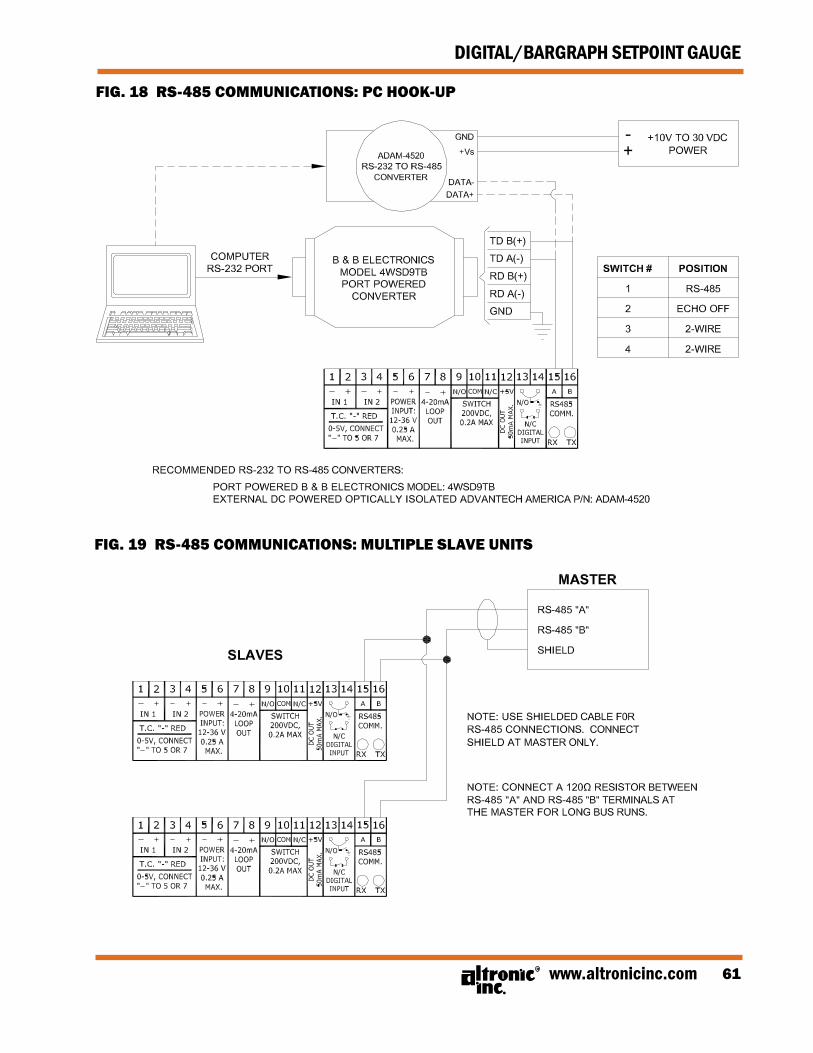
4.6 RS-485 COMMUNICATIONS WIRING: The DSG-1682DUPS gauge can communicate to other instruments,
PC’s or PLC’s via the two serial RS-485 communication wires. Use a two-conductor shielded cable of fine gauge stranded wire and con-nect the wires to the terminals marked RS485 A and RS485 B. Connect to the other communication device A to A(−) and B to B(+). Connect the shield wire to the master device only. (FIGS. 18 & 19)
4.7 HAzARDOUS AREA OPERATION: The DSG-1682DUPS gauge is CSA certified for CLASS I, DIVISION 2, GROUPS
C & D areas. DSG-1682DUPS gauge is certified as a component only and is required to be installed in a suitable enclosure where the suit-ability of the combination is subject to the local inspection author-ity having jurisdiction. The power connections to the DSG-1682DUPS gauge must be in accordance with the National Electrical Code and in Canada, the Canadian Electrical Code. In addition, the following re-quirements must be met:
• Run the sensor wires leaving the panel in a separate conduit from all other wiring and keep them separate throughout the installation.
• Power wiring and wiring to the transducers must have a grade of insulation capable of withstanding an AC voltage of 500 volts RMS.
• In general, run wires in separate conduits and junction boxes from high voltage wires such as ignition, fuel valve, and other high voltage wiring.
ExPLOSION HAzARD - DO NOT DISCONNECT EQUIPMENT IN DIV. 2 ENVIRONMENT UNLESS POWER IS SWITCHED OFF OR THE AREA IS KNOWN TO BE NON-HAzARDOUS.WARNING:
4.8 TESTING SENSOR LEADS: If it becomes necessary to check sensor to terminal strip wiring
with an ohmmeter or other checker, first disconnect the sensor wires from the gauge. This will prevent possible damage to the de-vice’s sensitive low voltage detection circuitry.
www.altronicinc.com 7
DIGITAL/BARGRAPH SETPOINT GAUGE
5.0 HOME SCREEN
5.1 The DSG-1682DUPS gauge has 2 sets of HOME SCREENS (3 sets if PID is con-figured). The first two sets of home screens shows the displayed data and other pertinent information. The third set shows the PID screens if the 1682 is set up for either the PID-CH1 or MAPPING mode.
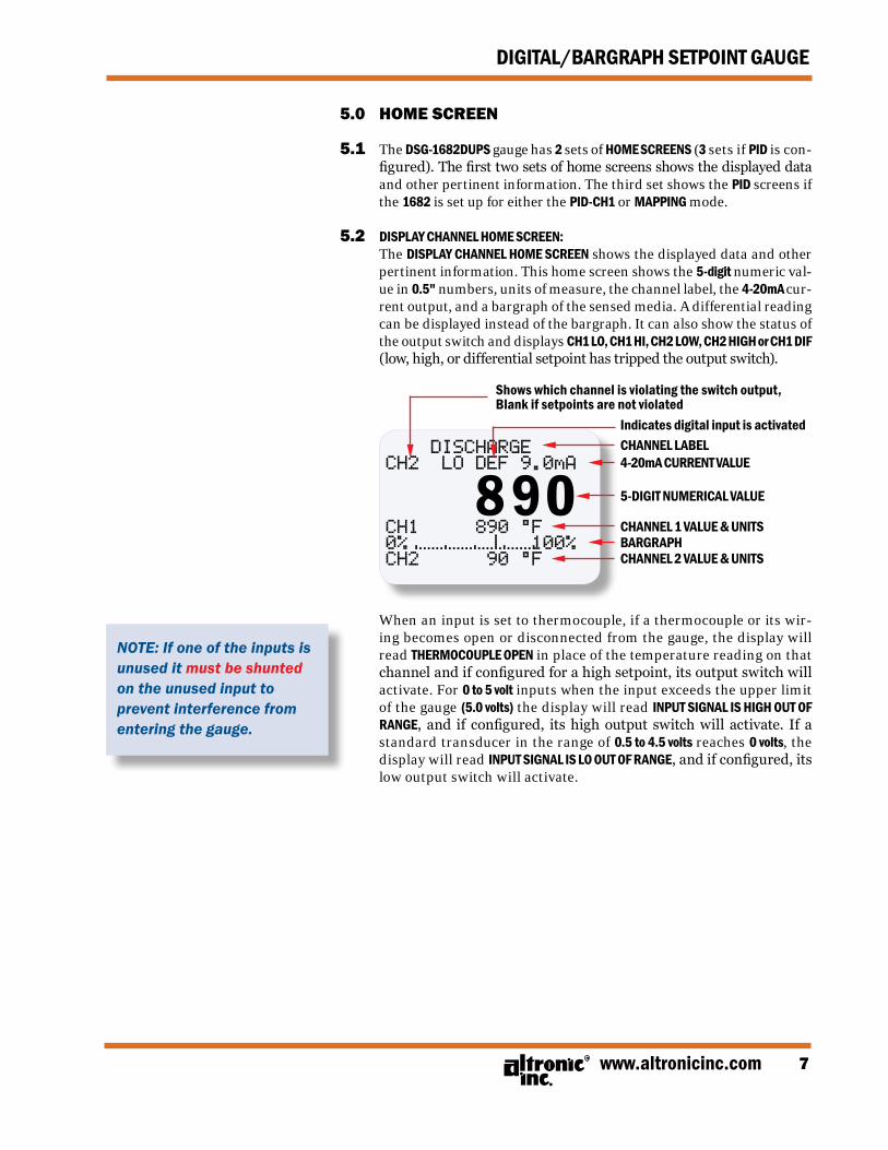
5.2 DISPLAY CHANNEL HOME SCREEN: The DISPLAY CHANNEL HOME SCREEN shows the displayed data and other
pertinent information. This home screen shows the 5-digit numeric val-ue in 0.5" numbers, units of measure, the channel label, the 4-20mA cur-rent output, and a bargraph of the sensed media. A differential reading can be displayed instead of the bargraph. It can also show the status of the output switch and displays CH1 LO, CH1 HI, CH2 LOW, CH2 HIGH or CH1 DIF (low, high, or differential setpoint has tripped the output switch).
Indicates digital input is activatedCHANNEL LABEL4-20mA CURRENT VALUE
5-DIGIT NUMERICAL VALUE
CHANNEL 1 VALUE & UNITS BARGRAPHCHANNEL 2 VALUE & UNITS
DISCHARGECH2 LO DEF 9.0mA
CH1 890 °F0% 100%CH2 90 °F
Shows which channel is violating the switch output, Blank if setpoints are not violated
When an input is set to thermocouple, if a thermocouple or its wir-ing becomes open or disconnected from the gauge, the display will read THERMOCOUPLE OPEN in place of the temperature reading on that channel and if configured for a high setpoint, its output switch will activate. For 0 to 5 volt inputs when the input exceeds the upper limit of the gauge (5.0 volts) the display will read INPUT SIGNAL IS HIGH OUT OF RANGE, and if configured, its high output switch will activate. If a standard transducer in the range of 0.5 to 4.5 volts reaches 0 volts, the display will read INPUT SIGNAL IS LO OUT OF RANGE, and if configured, its low output switch will activate.
NOTE: If one of the inputs is unused it must be shunted on the unused input to prevent interference from entering the gauge.
FORM DSG-1682DUPS II 6-098
DIGITAL/BARGRAPH SETPOINT GAUGE
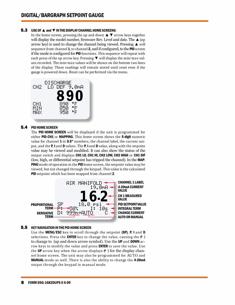
5.3 USE OF ▲ and ▼ IN THE DISPLAY CHANNEL HOME SCREENS: In the home screen, pressing the up and down ▲ ▼ arrow keys together
will display the model number, firmware Rev. Level and date. The ▲ (up arrow key) is used to change the channel being viewed. Pressing ▲ will sequence from channel 1, to channel 2, and if configured, to the PID screen if the mode is configured for PID functions. This sequence will repeat with each press of the up arrow key. Pressing ▼ will display the min/max val-ues recorded. The min/max values will be shown on the bottom two lines of the display. These readings will remain stored until reset even if the gauge is powered down. Reset can be performed via the menu.
DISCHARGECH2 LO DEF 9.0mA
CH1 890 °FMIN 850 °FMAX 950 °F
5.4 PID HOME SCREEN The PID HOME SCREEN will be displayed if the unit is programmed for
either PID-CH1 or MAPPING. This home screen shows the 5-digit numeric value for channel 1 in 0.5" numbers, the channel label, the current out-put, and the P, I and D values. The P, I and D value, along with the setpoint value may be viewed and modified. It can also show the status of the output switch and displays CH1 LO, CH1 HI, CH2 LOW, CH2 HIGH or CH1 DIF (low, high, or differential setpoint has tripped the channel). In the MAP-PING mode of operation in the PID home screen, the setpoint value may be viewed, but not changed through the keypad. This value is the calculated PID setpoint which has been mapped from channel 2.
5.5 KEY NAVIGATION IN THE PID HOME SCREEN Use the MENU/ESC key to scroll through the setpoint (SP), P, I and D
selections. Press the ENTER key to change the value, causing the (~) to change to (up and down arrow symbol). Use the UP and DOWN ar-row keys to modify the value and press ENTER to save the value. Use the UP arrow key when the arrow displays (~) for the display chan-nel home screen. The unit may also be programmed for AUTO and MANUAL mode as well. There is also the ability to change the 4-20mA output through the keypad in manual mode.
www.altronicinc.com 9
DIGITAL/BARGRAPH SETPOINT GAUGE
6.0 KEYPAD DESCRIPTION
6.1 The DSG-1682DUPS gauge contains a four-key front keypad which is used to view or change the setpoint values, configure the gauge, and to calibrate the gauge. The front panel keys are MENU/ESC, ENTER, and ▲, ▼ (up and down arrow keys).
6.2 MENU/ESC: The MENU/ESC key is used to enter the gauge configuration menu.
The MENU/ESC (escape) key can also be used at any time when in the configuration menu to return to the home screen. When the MENU/ESC key is pressed, prior to pressing ENTER, in any configuration mode, any changed values are ignored (not stored in memory), the configuration returns to the previous values and the display returns to the home screen.
6.3 ENTER: The ENTER key is used throughout the menu to proceed through
the configuration and to accept the data to be saved. Throughout configuration when a change has been made and is to be saved to memory, press ENTER and the display will read SAVED, and the new data or configuration will be stored in the nonvolatile memory.
6.4 ▲ AND ▼: The up and down arrow keys are used to scroll through the selec-
tions in the menu and to increase or decrease values during con-figuration and calibration. Each key when held will rapidly increase or decrease display values.
FORM DSG-1682DUPS II 6-0910
DIGITAL/BARGRAPH SETPOINT GAUGE
7.0 INITIAL OPERATION
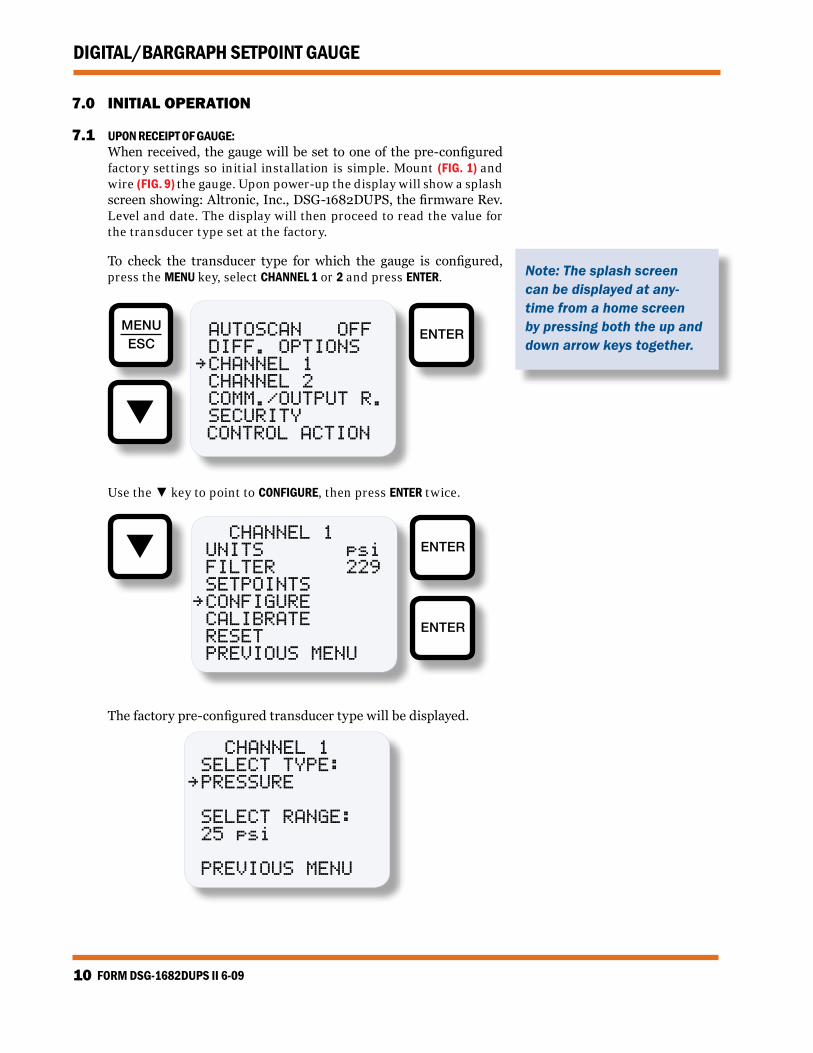
7.1 UPON RECEIPT OF GAUGE: When received, the gauge will be set to one of the pre-configured
factory settings so initial installation is simple. Mount (FIG. 1) and wire (FIG. 9) the gauge. Upon power-up the display will show a splash screen showing: Altronic, Inc., DSG-1682DUPS, the firmware Rev. Level and date. The display will then proceed to read the value for the transducer type set at the factory.
To check the transducer type for which the gauge is configured, press the MENU key, select CHANNEL 1 or 2 and press ENTER.
AUTOSCAN OFF DIFF. OPTIONS~ CHANNEL 1 CHANNEL 2 COMM./OUTPUT R. SECURITY CONTROL ACTION
MENUESC
ENTER
Use the ▼ key to point to CONFIGURE, then press ENTER twice.
ENTER
ENTER
CHANNEL 1 UNITS psi FILTER 229 SETPOINTS~ CONFIGURE CALIbRATE RESET PREvIOUS MENU
The factory pre-configured transducer type will be displayed.
Note: The splash screen can be displayed at any-time from a home screen by pressing both the up and down arrow keys together.
www.altronicinc.com 11
DIGITAL/BARGRAPH SETPOINT GAUGE
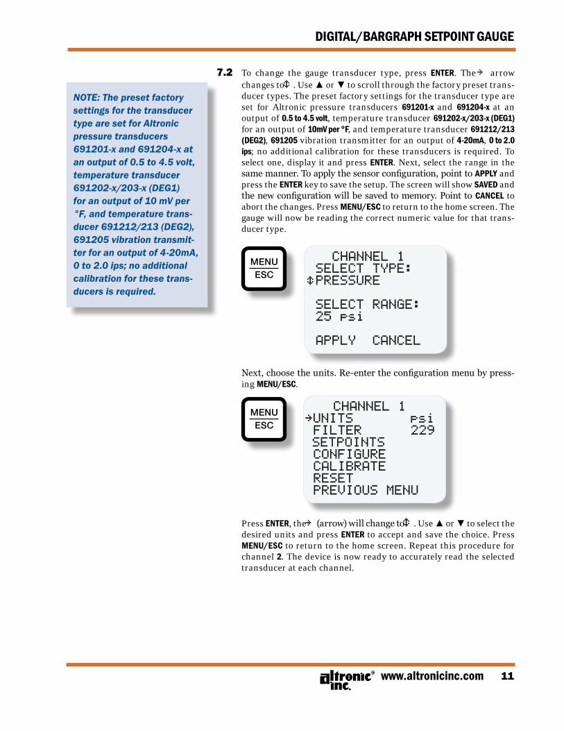
7.2 To change the gauge transducer type, press ENTER. The ~ arrow changes to é. Use ▲ or ▼ to scroll through the factory preset trans-ducer types. The preset factory settings for the transducer type are set for Altronic pressure transducers 691201-x and 691204-x at an output of 0.5 to 4.5 volt, temperature transducer 691202-x/203-x (DEG1) for an output of 10mV per °F, and temperature transducer 691212/213 (DEG2), 691205 vibration transmitter for an output of 4-20mA, 0 to 2.0 ips; no additional calibration for these transducers is required. To select one, display it and press ENTER. Next, select the range in the same manner. To apply the sensor configuration, point to APPLY and press the ENTER key to save the setup. The screen will show SAVED and the new configuration will be saved to memory. Point to CANCEL to abort the changes. Press MENU/ESC to return to the home screen. The gauge will now be reading the correct numeric value for that trans-ducer type.
Press ENTER, the ~ (arrow) will change to é. Use ▲ or ▼ to select the desired units and press ENTER to accept and save the choice. Press MENU/ESC to return to the home screen. Repeat this procedure for channel 2. The device is now ready to accurately read the selected transducer at each channel.
7.0 INITIAL OPERATION
7.1 UPON RECEIPT OF GAUGE: When received, the gauge will be set to one of the pre-configured
factory settings so initial installation is simple. Mount (FIG. 1) and wire (FIG. 9) the gauge. Upon power-up the display will show a splash screen showing: Altronic, Inc., DSG-1682DUPS, the firmware Rev. Level and date. The display will then proceed to read the value for the transducer type set at the factory.
To check the transducer type for which the gauge is configured, press the MENU key, select CHANNEL 1 or 2 and press ENTER.
Use the ▼ key to point to CONFIGURE, then press ENTER twice.
The factory pre-configured transducer type will be displayed.
NOTE: The preset factory settings for the transducer type are set for Altronic pressure transducers 691201-x and 691204-x at an output of 0.5 to 4.5 volt, temperature transducer 691202-x/203-x (DEG1) for an output of 10 mV per °F, and temperature trans-ducer 691212/213 (DEG2), 691205 vibration transmit-ter for an output of 4-20mA, 0 to 2.0 ips; no additional calibration for these trans-ducers is required.
FORM DSG-1682DUPS II 6-0912
DIGITAL/BARGRAPH SETPOINT GAUGE
8.0 GAUGE CONFIGURATION
8.1 This section describes, in detail, how to configure the gauge. Each heading is a menu selection.
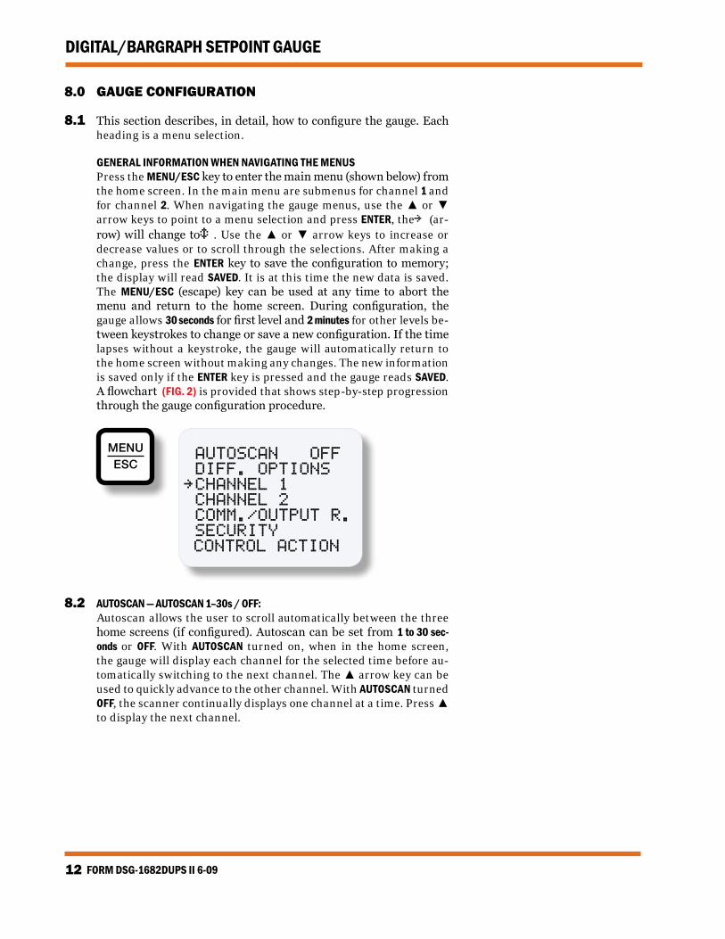
GENERAL INFORMATION WHEN NAVIGATING THE MENUS Press the MENU/ESC key to enter the main menu (shown below) from
the home screen. In the main menu are submenus for channel 1 and for channel 2. When navigating the gauge menus, use the ▲ or ▼ arrow keys to point to a menu selection and press ENTER, the ~ (ar-row) will change to é. Use the ▲ or ▼ arrow keys to increase or decrease values or to scroll through the selections. After making a change, press the ENTER key to save the configuration to memory; the display will read SAVED. It is at this time the new data is saved. The MENU/ESC (escape) key can be used at any time to abort the menu and return to the home screen. During configuration, the gauge allows 30 seconds for first level and 2 minutes for other levels be-tween keystrokes to change or save a new configuration. If the time lapses without a keystroke, the gauge will automatically return to the home screen without making any changes. The new information is saved only if the ENTER key is pressed and the gauge reads SAVED. A flowchart (FIG. 2) is provided that shows step-by-step progression through the gauge configuration procedure.
MENUESC
AUTOSCAN OFF DIFF. OPTIONS~ CHANNEL 1 CHANNEL 2 COMM./OUTPUT R. SECURITY CONTROL ACTION
8.2 AUTOSCAN — AUTOSCAN 1–30s / OFF: Autoscan allows the user to scroll automatically between the three
home screens (if configured). Autoscan can be set from 1 to 30 sec-onds or OFF. With AUTOSCAN turned on, when in the home screen, the gauge will display each channel for the selected time before au-tomatically switching to the next channel. The ▲ arrow key can be used to quickly advance to the other channel. With AUTOSCAN turned OFF, the scanner continually displays one channel at a time. Press ▲ to display the next channel.
www.altronicinc.com 13
DIGITAL/BARGRAPH SETPOINT GAUGE
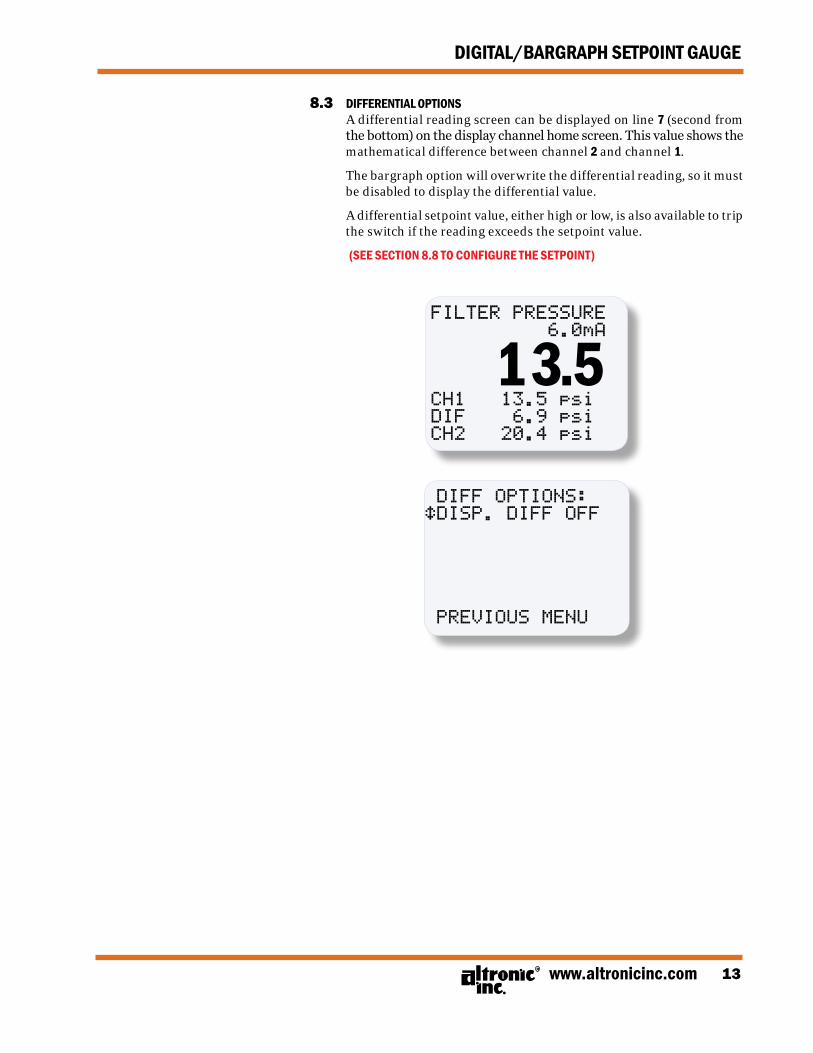
8.3 DIFFERENTIAL OPTIONS A differential reading screen can be displayed on line 7 (second from
the bottom) on the display channel home screen. This value shows the mathematical difference between channel 2 and channel 1.
The bargraph option will overwrite the differential reading, so it must be disabled to display the differential value.
A differential setpoint value, either high or low, is also available to trip the switch if the reading exceeds the setpoint value.
(SEE SECTION 8.8 TO CONFIGURE THE SETPOINT)
FILTER PRESSURE 6.0mA
CH1 13.5 psiDIF 6.9 psi CH2 20.4 psi
13.5
DIFF OPTIONS:éDISP. DIFF OFF
PREvIOUS MENU
FORM DSG-1682DUPS II 6-0914
DIGITAL/BARGRAPH SETPOINT GAUGE
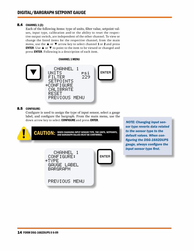
8.4 CHANNEL 1 (2): Each of the following items: type of units, filter value, setpoint val-
ues, input type, calibration and/or the ability to reset the respec-tive output switch, are independent of the other channel. To view or change the listed items for the respective channel, from the main menu, use the ▲ or ▼ arrow key to select channel 1 or 2 and press ENTER. Use ▲ or ▼ to point to the item to be viewed or changed and press ENTER. Following is a description of each item.
CHANNEL 1 MENU
ENTER CHANNEL 1 UNITS psi FILTER 229 SETPOINTS~CONFIGURE CALIbRATE RESET PREvIOUS MENU
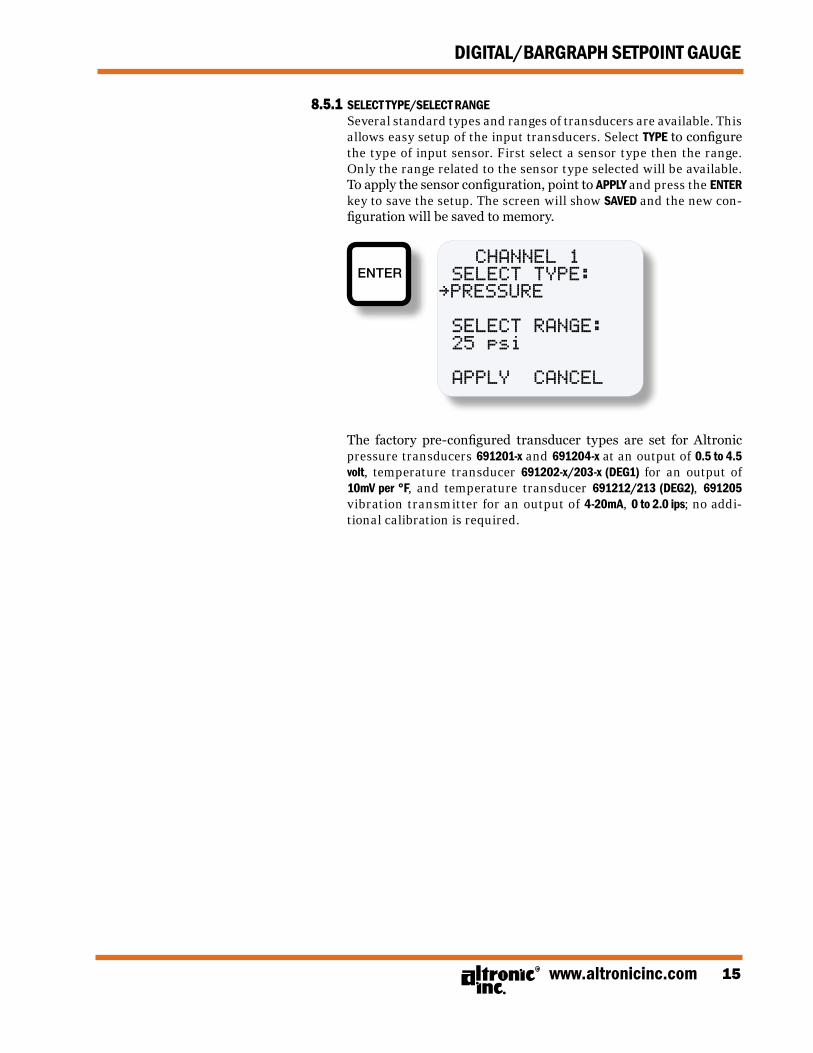
8.5 CONFIGURE: Configure is used to assign the type of input sensor, select a gauge
label, and configure the bargraph. From the main menu, use the down arrow key to select CONFIGURE and press ENTER.
CAUTION: WHEN CHANGING INPUT SENSOR TYPE, THE UNITS, SETPOINTS, AND BARGRAPH VALUES MUST BE CONFIRMED.
CHANNEL 1 CONFIGURE:~TYPE GAUGE LAbEL bARGRAPH PREvIOUS MENU
ENTER
NOTE: Changing input sen-sor type reverts data related to the sensor type to the default values. When con-figuring the DSG-1682DUPS gauge, always configure the input sensor type first.
www.altronicinc.com 15
DIGITAL/BARGRAPH SETPOINT GAUGE
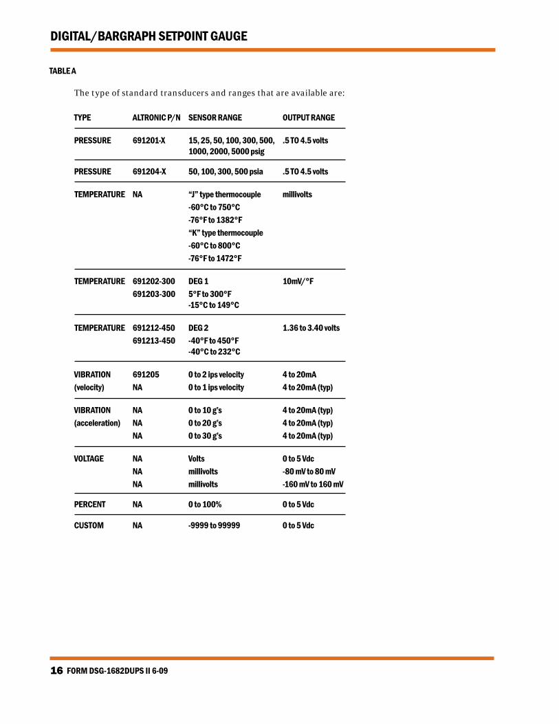
8.5.1 SELECT TYPE/SELECT RANGE Several standard types and ranges of transducers are available. This
allows easy setup of the input transducers. Select TYPE to configure the type of input sensor. First select a sensor type then the range. Only the range related to the sensor type selected will be available. To apply the sensor configuration, point to APPLY and press the ENTER key to save the setup. The screen will show SAVED and the new con-figuration will be saved to memory.
The factory pre-configured transducer types are set for Altronic pressure transducers 691201-x and 691204-x at an output of 0.5 to 4.5 volt, temperature transducer 691202-x/203-x (DEG1) for an output of 10mV per °F, and temperature transducer 691212/213 (DEG2), 691205 vibration transmitter for an output of 4-20mA, 0 to 2.0 ips; no addi-tional calibration is required.
FORM DSG-1682DUPS II 6-0916
DIGITAL/BARGRAPH SETPOINT GAUGE
TABLE A
The type of standard transducers and ranges that are available are:
TEMPERATURE NA “J” type thermocouple millivolts -60°C to 750°C -76°F to 1382°F “K” type thermocouple -60°C to 800°C -76°F to 1472°F
TEMPERATURE 691202-300 DEG 1 10mV/°F 691203-300 5°F to 300°F -15°C to 149°C
TEMPERATURE 691212-450 DEG 2 1.36 to 3.40 volts 691213-450 -40°F to 450°F -40°C to 232°C
VIBRATION 691205 0 to 2 ips velocity 4 to 20mA(velocity) NA 0 to 1 ips velocity 4 to 20mA (typ)
VIBRATION NA 0 to 10 g’s 4 to 20mA (typ)(acceleration) NA 0 to 20 g’s 4 to 20mA (typ) NA 0 to 30 g’s 4 to 20mA (typ)
VOLTAGE NA Volts 0 to 5 Vdc NA millivolts -80 mV to 80 mV NA millivolts -160 mV to 160 mV
PERCENT NA 0 to 100% 0 to 5 Vdc
CUSTOM NA -9999 to 99999 0 to 5 Vdc
www.altronicinc.com 17
DIGITAL/BARGRAPH SETPOINT GAUGE
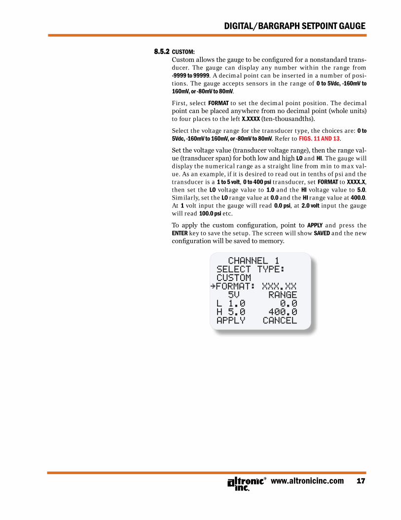
8.5.2 CUSTOM: Custom allows the gauge to be configured for a nonstandard trans-
ducer. The gauge can display any number within the range from -9999 to 99999. A decimal point can be inserted in a number of posi-tions. The gauge accepts sensors in the range of 0 to 5Vdc, -160mV to 160mV, or -80mV to 80mV.
First, select FORMAT to set the decimal point position. The decimal
point can be placed anywhere from no decimal point (whole units) to four places to the left x.xxxx (ten-thousandths).
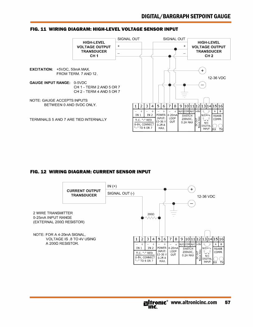
Select the voltage range for the transducer type, the choices are: 0 to 5Vdc, -160mV to 160mV, or -80mV to 80mV. Refer to FIGS. 11 AND 13.
Set the voltage value (transducer voltage range), then the range val-ue (transducer span) for both low and high LO and HI. The gauge will display the numerical range as a straight line from min to max val-ue. As an example, if it is desired to read out in tenths of psi and the transducer is a 1 to 5 volt, 0 to 400 psi transducer, set FORMAT to xxxx.x, then set the LO voltage value to 1.0 and the HI voltage value to 5.0. Similarly, set the LO range value at 0.0 and the HI range value at 400.0. At 1 volt input the gauge will read 0.0 psi, at 2.0 volt input the gauge will read 100.0 psi etc.
To apply the custom configuration, point to APPLY and press the ENTER key to save the setup. The screen will show SAVED and the new configuration will be saved to memory.
CHANNEL 1 SELECT TYPE: CUSTOM~FORMAT: XXX.XX 5v RANGE L 1.0 0.0 H 5.0 400.0 APPLY CANCEL
FORM DSG-1682DUPS II 6-0918
DIGITAL/BARGRAPH SETPOINT GAUGE
8.5.3 UNITS FOR CUSTOM SENSORS: Upon completion of configuring a custom sensor type, a units-
of-measure should be selected. Press the MENU/ESC key and select UNITS. All of the standard units-of-measure are available from the UNITS menu as well as the ability to create a custom unit label up to 5 characters long. Note that the unit-of-measure selected for a custom transducer type is just a label and is not tied to the transducer type as it is when selecting a standard transducer type. Following are the standard units-of-measure available from the UNITS menu: *NONE*, *CUSTOM*, Amps, Hz, %, Volts, mV, in/s, mm/s, cm/s, g’s, m/s², ft/s², psi, psig, psia, KPa, bar, mbar, inH2O, inHg, mmH2O, mmHg, kg/cm², torr, °F, °C, and °K.
Select *NONE* for no unit label. Select *CUSTOM* and input a custom
label through modbus. See the modbus register list for the register number. Note that CUSTOM will not appear on the home screen, it is used as a pointer to the ModBus register.
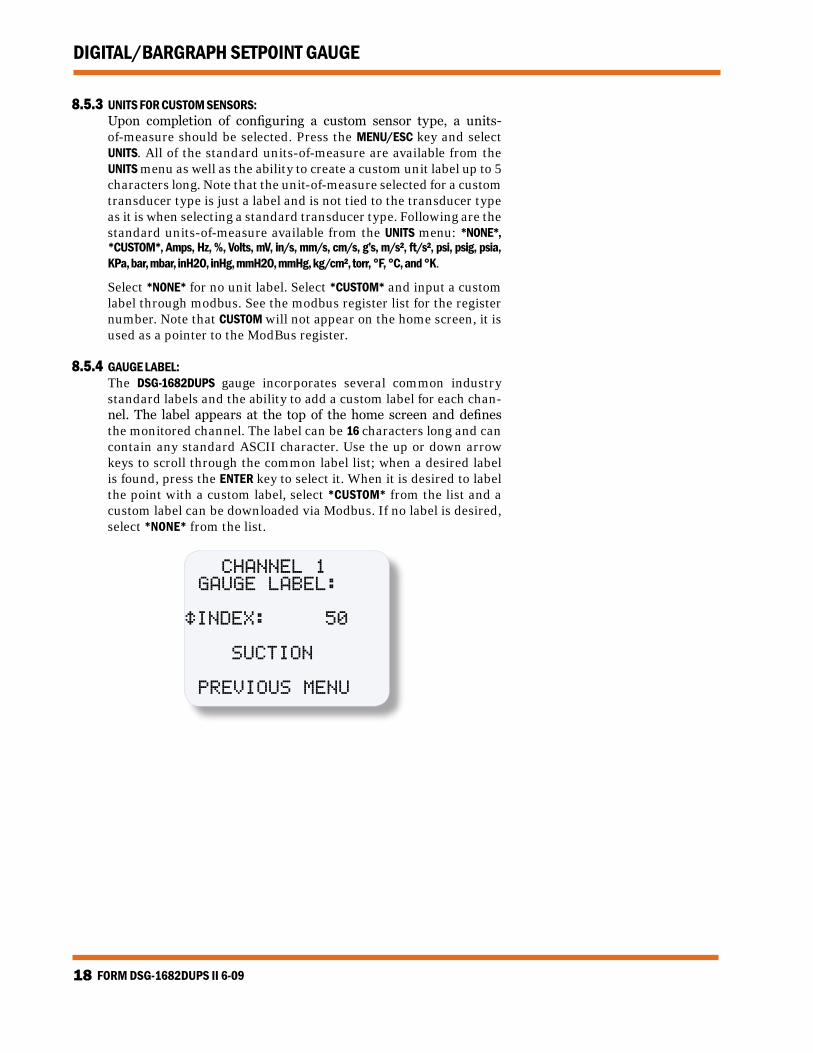
8.5.4 GAUGE LABEL: The DSG-1682DUPS gauge incorporates several common industry
standard labels and the ability to add a custom label for each chan-nel. The label appears at the top of the home screen and defines the monitored channel. The label can be 16 characters long and can contain any standard ASCII character. Use the up or down arrow keys to scroll through the common label list; when a desired label is found, press the ENTER key to select it. When it is desired to label the point with a custom label, select *CUSTOM* from the list and a custom label can be downloaded via Modbus. If no label is desired, select *NONE* from the list.
CHANNEL 1 GAUGE LAbEL: éINDEX: 50
SUCTION
PREvIOUS MENU
www.altronicinc.com 19
DIGITAL/BARGRAPH SETPOINT GAUGE
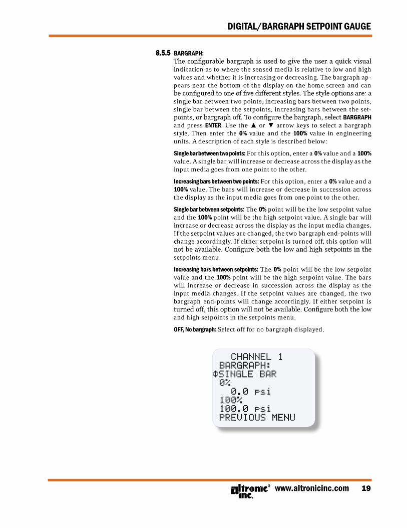
8.5.5 BARGRAPH: The configurable bargraph is used to give the user a quick visual
indication as to where the sensed media is relative to low and high values and whether it is increasing or decreasing. The bargraph ap-pears near the bottom of the display on the home screen and can be configured to one of five different styles. The style options are: a single bar between two points, increasing bars between two points, single bar between the setpoints, increasing bars between the set-points, or bargraph off. To configure the bargraph, select BARGRAPH and press ENTER. Use the ▲ or ▼ arrow keys to select a bargraph style. Then enter the 0% value and the 100% value in engineering units. A description of each style is described below:
Single bar between two points: For this option, enter a 0% value and a 100%
value. A single bar will increase or decrease across the display as the input media goes from one point to the other.
Increasing bars between two points: For this option, enter a 0% value and a
100% value. The bars will increase or decrease in succession across the display as the input media goes from one point to the other.
Single bar between setpoints: The 0% point will be the low setpoint value
and the 100% point will be the high setpoint value. A single bar will increase or decrease across the display as the input media changes. If the setpoint values are changed, the two bargraph end-points will change accordingly. If either setpoint is turned off, this option will not be available. Configure both the low and high setpoints in the setpoints menu.
Increasing bars between setpoints: The 0% point will be the low setpoint
value and the 100% point will be the high setpoint value. The bars will increase or decrease in succession across the display as the input media changes. If the setpoint values are changed, the two bargraph end-points will change accordingly. If either setpoint is turned off, this option will not be available. Configure both the low and high setpoints in the setpoints menu.
OFF, No bargraph: Select off for no bargraph displayed.
CHANNEL 1 bARGRAPH:éSINGLE bAR 0% 0.0 psi 100% 100.0 psi PREvIOUS MENU
FORM DSG-1682DUPS II 6-0920
DIGITAL/BARGRAPH SETPOINT GAUGE
8.6 UNITS: There are several units-of-measure available as standard selections
in the gauge. Only the units relevant to the selected input sensor type will be available. Following are the available units for each type of input sensor.
• Pressure units: psi, psig, psia, KPa, bar, mbar, inH2O, inHg, mmH2O, mmHg, kg/cm², and torr • Temperature units: °F, °C, and °K • Vibration units: in/s, mm/s, cm/s, g’s, m/s², and ft/s² • Voltage units: Volts, mV • Percent units: %
The unit indicators appear on the right side of the display. When changing to a new unit indicator, the displayed numeric value is au-tomatically converted to the new unit value. To change the units, use the ▲ or ▼ key to point to UNITS and press the ENTER key; the previ-ously programmed unit indicator will appear. Use the ▲ or ▼ key to select one of the available indicators, and press ENTER to accept and save the change. The display will read SAVED. To return to the home screen press MENU/ESC. The new unit indicator selected and the numeric value converted to the selected units will be displayed on the home screen. Up to 5-digits of a custom units-of-measure can be displayed. It can be configured through Modbus.
8.7 FILTER: The display filter can be used to stabilize the display reading of a
changing input. Filtering is done in both hardware and software. The software filter is adjustable; the rate of change is less for large values. The filter value is read-out in a number from 1 to 255, 1 being no filter value and 255 being maximum filter value. Below are some typical filter values and their effect on the display reading. Settling values are approximate times in seconds to reach 90% of new read-ing. To set the filter value, use the ▲ or ▼ key to point to FILTER and press ENTER. The display will read the previously set filter value. Use the ▲ or ▼ keys to increase or decrease the filter value and press ENTER to save the new filter value.
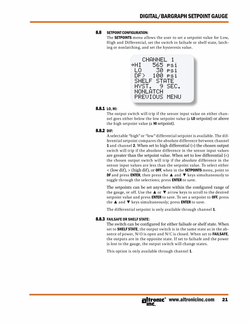
8.8 SETPOINT CONFIGURATION: The SETPOINTS menu allows the user to set a setpoint value for Low,
High and Differential, set the switch to failsafe or shelf state, latch-ing or nonlatching, and set the hysteresis value.
CHANNEL 1~HI 565 psi LO 30 psi DF> 100 psi SHELF STATE HYST. 9 SEC. NONLATCH PREvIOUS MENU
8.8.1 LO, HI: The output switch will trip if the sensor input value on either chan-
nel goes either below the low setpoint value (a LO setpoint) or above the high setpoint value (a HI setpoint).
8.8.2 DIF: A selectable “high” or “low” differential setpoint is available. The dif-
ferential setpoint compares the absolute difference between channel 1 and channel 2. When set to high differential (>) the chosen output switch will trip if the absolute difference in the sensor input values are greater than the setpoint value. When set to low differential (<) the chosen output switch will trip if the absolute difference in the sensor input values are less than the setpoint value. To select either < (low dif), > (high dif), or OFF, when in the SETPOINTS menu, point to DF and press ENTER, then press the ▲ and ▼ keys simultaneously to toggle through the selections; press ENTER to save.
The setpoints can be set anywhere within the configured range of the gauge, or off. Use the ▲ or ▼ arrow keys to scroll to the desired setpoint value and press ENTER to save. To set a setpoint to OFF, press the ▲ and ▼ keys simultaneously; press ENTER to save.
The differential setpoint is only available through channel 1.
8.8.3 FAILSAFE OR SHELF STATE: The switch can be configured for either failsafe or shelf state. When
set to SHELF STATE, the output switch is in the same state as in the ab-sence of power, N/O is open and N/C is closed. When set to FAILSAFE, the outputs are in the opposite state. If set to failsafe and the power is lost to the gauge, the output switch will change states.
This option is only available through channel 1.
FORM DSG-1682DUPS II 6-0922
DIGITAL/BARGRAPH SETPOINT GAUGE
8.8.4 HYSTERESIS: Hysteresis can be used when the output switch is configured as non-
latching to prevent the output switch from oscillating or turning on and off around the setpoint. The hysteresis is implemented as a time, in seconds, that begins when the sensor input value returns to within the setpoint value limits. When the input value returns to within the setpoint value limits, the hysteresis timer starts and the switch stays tripped for the configured hysteresis time. If during the hysteresis time the setpoint is violated again, the hysteresis timer starts over. The hysteresis value can be set from 1 to 99 seconds. To set the hys-teresis value, point to HYST and press the ENTER key. Use ▲ or ▼ to increase or decrease the hysteresis time and press ENTER to save the new value.
8.8.5 LATCH/NONLATCH: Each channel can be configured for latching or nonlatching. When
set to LATCH the switch will stay tripped continuously until it is ei-ther reset manually (using RESET in the channel x menu) or by cy-cling the power. When set to nonlatch the switch will stay tripped outside the setpoint limits but will automatically reset when the input sensor value returns to within the limits plus the hysteresis time set.
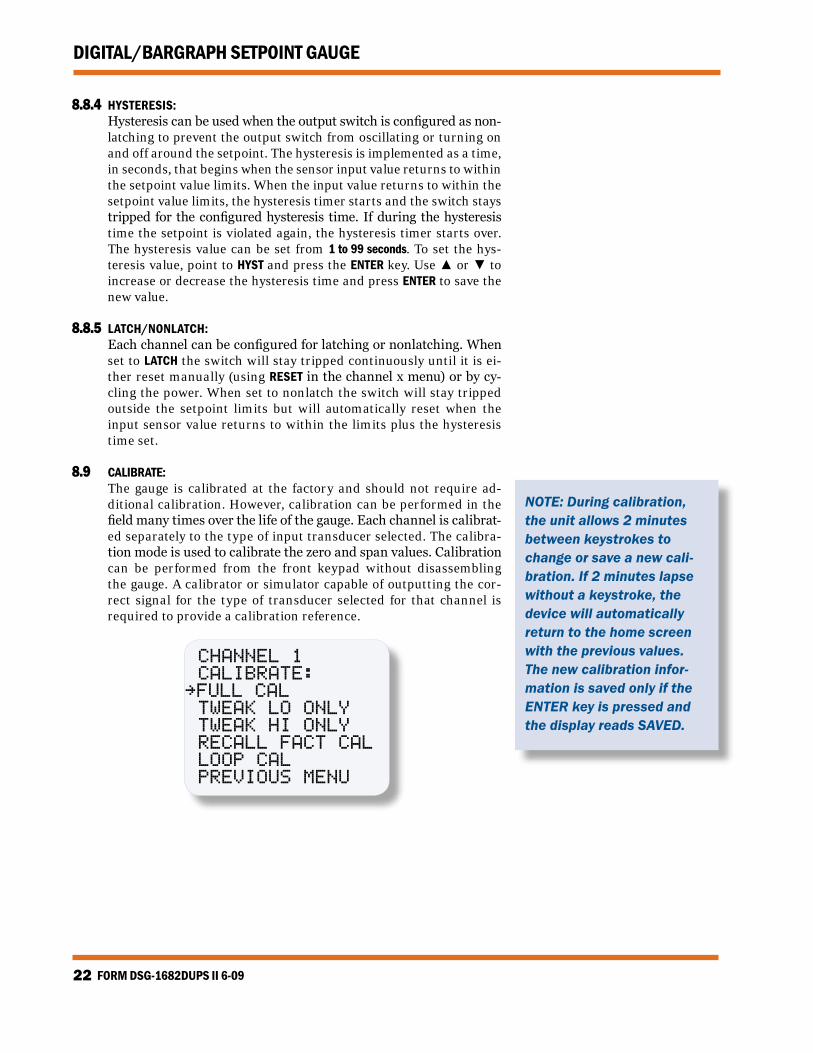
8.9 CALIBRATE: The gauge is calibrated at the factory and should not require ad-
ditional calibration. However, calibration can be performed in the field many times over the life of the gauge. Each channel is calibrat-ed separately to the type of input transducer selected. The calibra-tion mode is used to calibrate the zero and span values. Calibration can be performed from the front keypad without disassembling the gauge. A calibrator or simulator capable of outputting the cor-rect signal for the type of transducer selected for that channel is required to provide a calibration reference.
CHANNEL 1 CALIbRATE:~FULL CAL TWEAK LO ONLY TWEAK HI ONLY RECALL FACT CAL LOOP CAL PREvIOUS MENU
NOTE: During calibration, the unit allows 2 minutes between keystrokes to change or save a new cali-bration. If 2 minutes lapse without a keystroke, the device will automatically return to the home screen with the previous values. The new calibration infor-mation is saved only if the ENTER key is pressed and the display reads SAVED.
www.altronicinc.com 23
DIGITAL/BARGRAPH SETPOINT GAUGE
8.9.1 CALIBRATION PROCEDURE: Connect the appropriate calibrator or simulator (for thermocouples use
the proper type of thermocouple extension wire) to the gauge for channel 1 or 2, follow the hook-up drawing for that sensor type. Be sure that the sensor type and the engineering units of the calibrator match the type and engineering units of the instrument before performing a calibration.
To calibrate the gauge, select CALIBRATE from the channel 1 or 2 menu
and press the ENTER key. Select FULL CAL and press ENTER. The display will read SET LO POINT ON CALIBRATOR AND PRESS ENTER. Adjust the cali-brator/simulator at or near zero or a very low reading and press ENTER; the display will show SAMPLING, then ADJUST LO POINT TO MATCH CALIBRA-TOR. Use the ▲ or ▼ arrow keys to increase or decrease the display reading to match the setting of the simulator and press ENTER. The dis-play will show SET HI POINT ON CALIBRATOR AND PRESS ENTER. Adjust the simulator at or near the span value of the transducer or a very high reading and press ENTER; the display will show SAMPLING, then ADJUST HI POINT TO MATCH CALIBRATOR. Again use the ▲ or ▼ arrow keys to in-crease or decrease the display reading to match the simulator and press ENTER. The display will read CALIBRATION VALUES SAVED!. The gauge will return to the home screen with the new calibration values stored in memory.
8.9.2 The DSG-1682DUPS gauge has a feature that allows a slight adjustment of either the zero or span values individually. This type of calibration can be used to “tweak” the readout to match that of a known value without actually performing a formal calibration procedure. This ad-justment is independent for each channel and must be performed on that individual channel. Please note that this type of adjustment will invalidate calibration settings from the FULL CAL procedures.
TWEAK LO ONLY: To make a small adjustment on the zero calibration value of the
gauge, enter the calibration mode by selecting CALIBRATE and press ENTER; select TWEAK LO ONLY from the menu and press ENTER. The dis-play will show SET LO POINT ON CALIBRATOR AND PRESS ENTER. Adjust the calibrator/simulator at or near zero or a very low reading and press ENTER; the display will show SAMPLING, then ADJUST LO POINT TO MATCH CALIBRATOR. Use the ▲ or ▼ arrow keys to increase or decrease the display reading to match the calibrator and press ENTER. The dis-play will read CALIBRATION VALUES SAVED!. The gauge will return to the home screen with the new zero calibration value stored in memory.
TWEAK HI ONLY: To make a small adjustment on the span calibration value of the
gauge, enter the calibration mode by selecting CALIBRATE and press ENTER; select TWEAK HI ONLY from the menu and press ENTER. The dis-play will show SET HI POINT ON CALIBRATOR AND PRESS ENTER. Adjust the calibrator/simulator at or near the desired span value and press EN-TER; the display will show SAMPLING, then ADJUST HI POINT TO MATCH CALIBRATOR. Use the ▲ or ▼ arrow keys to increase or decrease the display reading to match the calibrator and press ENTER. The display will read CALIBRATION VALUES SAVED!. The gauge will return to the home screen with the new span calibration value stored in memory.
FORM DSG-1682DUPS II 6-0924
DIGITAL/BARGRAPH SETPOINT GAUGE
8.9.3 RECALL FACTORY CAL VALUES: The user can at any time during the life of the gauge reinstate the
factory calibration values for channel 1 or 2 independently. Select CALIBRATE from the CHANNEL 1 or CHANNEL 2 menu and press ENTER; select RECALL FACTORY CAL and press ENTER. The next screen will dis-play the configured type and range of input for the selected chan-nel. Select APPLY to confirm or CANCEL to decline and press ENTER. If APPLY is selected, the display will show CALIBRATION VALUES SAVED!. The gauge will return to the home screen with the factory default calibration values stored in memory. If CANCEL is selected, the gauge will retain the current calibration values. Press the ESC key to return to the home screen.
The calibration values only, will return to the factory default; all other settings will remain unchanged. If the transducer type or range is incorrect, press the MENU/ESC key to abort saving incorrect factory cal values. Configure the gauge for the desired input sensor type and range and then recall the factory cal values.
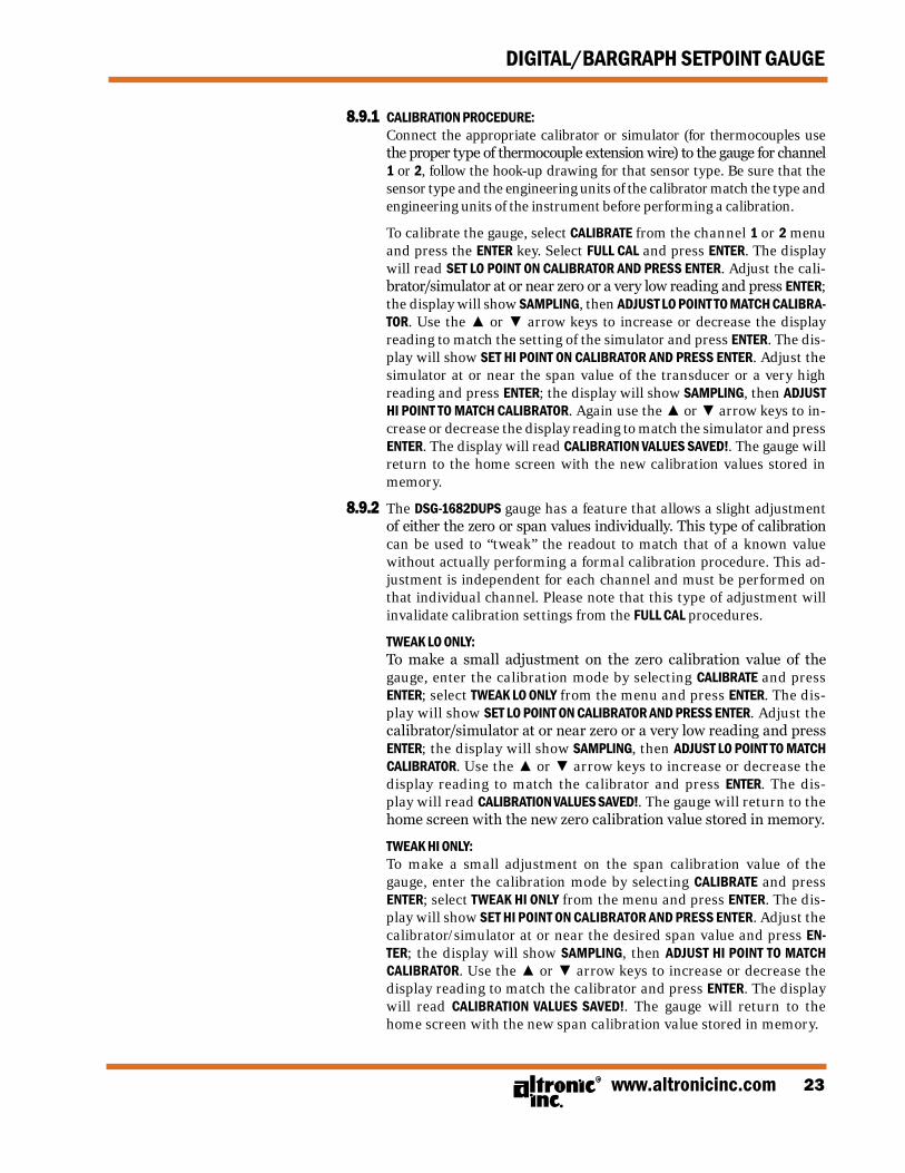
8.9.4 LOOP CAL: The current loop of the DSG-1682DUPS gauge is factory calibrated and
will not typically require field calibration. However, if desired, LOOP CAL can be used to calibrate the 4-20mA current loop output typically to meet the needs of a preselected loop resistor in the receiving de-vice. Please note that LOOP CAL calibrates the current loop hardware on the gauge, it is not to be used to configure the current loop output.
If it is necessary to re-calibrate the 4-20mA output, the following procedure can be used. Connect a digital milliamp meter in series with the loop output. Select CALIBRATE from the menu and press the ENTER key. Select LOOP CAL and press ENTER. The CALIBRATE LOOP menu is show below. The display will show the 4mA and 20mA counts num-bers for the digital to analog converter. With the arrow pointing to the 4mA counts value, press ENTER and use the ▲ or ▼ arrow key to increase or decrease the displayed counts number until the mea-sured loop current is equal to 4.00mA on the milliamp meter. Press ENTER, the display will show SAVED and the new 4mA value will be stored in memory. Select the 20mA counts value, press ENTER and use the ▲ or ▼ arrow key to increase or decrease the displayed counts number until the measured loop current is equal to 20.00mA on the milliamp meter and press ENTER. The display will read SAVED, and the new 20mA calibration value will be stored in memory. Press the MENU/ESC key to return to the home screen.
CALIbRATE LOOP:
4mA POINT~ 822 COUNTS 20mA POINTS 4086 COUNTS
PREvIOUS MENU
www.altronicinc.com 25
DIGITAL/BARGRAPH SETPOINT GAUGE
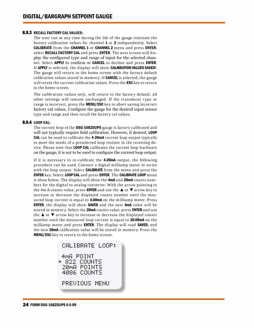
8.10 RESET: The reset selection in the menu is used to reset the output switch
when set to latching and also to re-zero the min/max reading for channel 1 or 2 independently. Since each output switch and the min/max reading is tied to its respective channel, a separate reset can be performed. To perform a reset, select either channel 1 or 2 from the menu, use ▲ or ▼ to scroll to RESET and press ENTER. Se-lect either OUTPUT SWITCH or MIN/MAx READING. Press ENTER and the display will show RESET!. A reset can also be performed by sending a reset command via the RS-485 Modbus RTU communications reg-ister.
8.10.1 OUTPUT SWITCH: Use the ▲ or ▼ arrow key to point to OUTPUT SWITCH and press ENTER;
The display will show RESET!.
CHANNEL 1 RESET:~OUTPUT SWITCH
MIN/MAX READING
PREvIOUS MENU
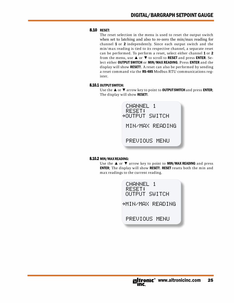
8.10.2 MIN/MAx READING: Use the ▲ or ▼ arrow key to point to MIN/MAx READING and press
ENTER; The display will show RESET!. RESET resets both the min and max readings to the current reading.
CHANNEL 1 RESET: OUTPUT SWITCH
~MIN/MAX READING
PREvIOUS MENU
FORM DSG-1682DUPS II 6-0926
DIGITAL/BARGRAPH SETPOINT GAUGE
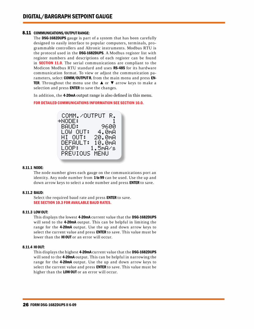
8.11 COMMUNICATIONS/OUTPUT RANGE: The DSG-1682DUPS gauge is part of a system that has been carefully
designed to easily interface to popular computers, terminals, pro-grammable controllers and Altronic instruments. Modbus RTU is the protocol used in the DSG-1682DUPS. A Modbus register list with register numbers and descriptions of each register can be found in SECTION 11.0. The serial communications are compliant to the Modicon Modbus RTU standard and uses RS-485 for its hardware communication format. To view or adjust the communication pa-rameters, select COMM/OUTPUT R. from the main menu and press EN-TER. Throughout the menu use the ▲ or ▼ arrow keys to make a selection and press ENTER to save the changes.
In addition, the 4-20mA output range is also defined in this menu.
FOR DETAILED COMMUNICATIONS INFORMATION SEE SECTION 10.0.
COMM./OUTPUT R.~NODE: 1 bAUD: 9600 LOW OUT: 4.0mA HI OUT: 20.0mA DEFAULT: 10.0mA LOOP: 1.5mA/s PREvIOUS MENU
8.11.1 NODE: The node number gives each gauge on the communications port an
identity. Any node number from 1 to 99 can be used. Use the up and down arrow keys to select a node number and press ENTER to save.
8.11.2 BAUD: Select the required baud rate and press ENTER to save. SEE SECTION 10.3 FOR AVAILABLE BAUD RATES.
8.11.3 LOW OUT: This displays the lowest 4-20mA current value that the DSG-1682DUPS
will send to the 4-20mA output. This can be helpful in limiting the range for the 4-20mA output. Use the up and down arrow keys to select the current value and press ENTER to save. This value must be lower than the HI OUT or an error will occur.
8.11.4 HI OUT: This displays the highest 4-20mA current value that the DSG-1682DUPS
will send to the 4-20mA output. This can be helpful in narrowing the range for the 4-20mA output. Use the up and down arrow keys to select the current value and press ENTER to save. This value must be higher than the LOW OUT or an error will occur.
www.altronicinc.com 27
DIGITAL/BARGRAPH SETPOINT GAUGE
8.11.5 DEFAULT (CURRENT): This displays the 4-20mA current value that will be sent to the
4-20mA output when the N/C digital input has been opened. Use the up and down arrow keys to select the current value and press ENTER to save. This value may be anywhere between 4 to 20mA range. The default current overrides both the HI and LOW OUT values.
8.11.6 LOOP: This value requires prior knowledge of PID controls in order
to fully understand this value. In a typical PID control, the 4-20mA output could swing rail-to-rail depending on the set-tings of the PID. Sometimes a limit to the change in 4-20mA is desired. This value sets a limit (or not) on the 4-20mA range that the controller will make to the 4-20mA output. If the loop is set to 1.5mA/s, the current output will not change by more than 1.5mA per second, independent of the PID error or the PID values. The range can be from .1mA/s up to 20.0mA/s which is the same as the TRUE PID setting. Use the up and down arrow keys to select the loop setting and press ENTER to save.
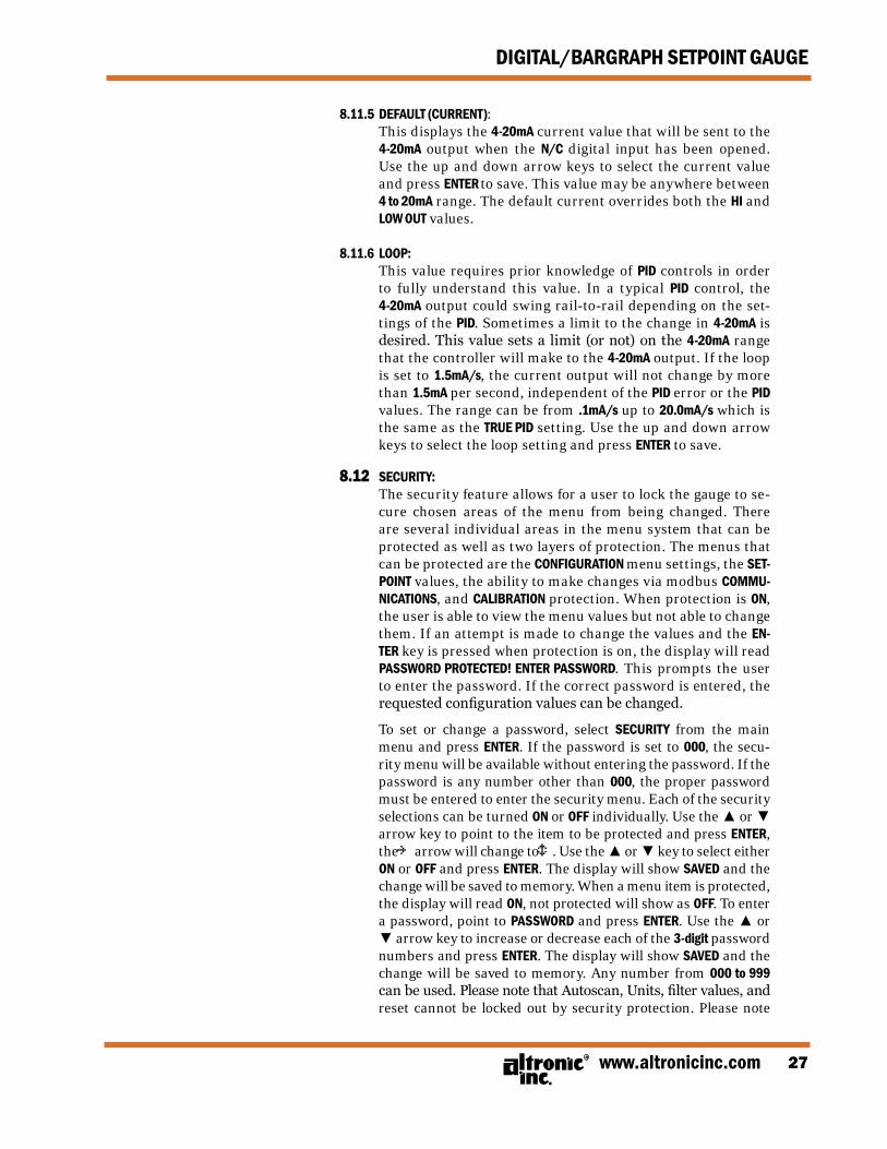
8.12 SECURITY: The security feature allows for a user to lock the gauge to se-
cure chosen areas of the menu from being changed. There are several individual areas in the menu system that can be protected as well as two layers of protection. The menus that can be protected are the CONFIGURATION menu settings, the SET-POINT values, the ability to make changes via modbus COMMU-NICATIONS, and CALIBRATION protection. When protection is ON, the user is able to view the menu values but not able to change them. If an attempt is made to change the values and the EN-TER key is pressed when protection is on, the display will read PASSWORD PROTECTED! ENTER PASSWORD. This prompts the user to enter the password. If the correct password is entered, the requested configuration values can be changed.
To set or change a password, select SECURITY from the main menu and press ENTER. If the password is set to 000, the secu-rity menu will be available without entering the password. If the password is any number other than 000, the proper password must be entered to enter the security menu. Each of the security selections can be turned ON or OFF individually. Use the ▲ or ▼ arrow key to point to the item to be protected and press ENTER, the ~ arrow will change to é. Use the ▲ or ▼ key to select either ON or OFF and press ENTER. The display will show SAVED and the change will be saved to memory. When a menu item is protected, the display will read ON, not protected will show as OFF. To enter a password, point to PASSWORD and press ENTER. Use the ▲ or ▼ arrow key to increase or decrease each of the 3-digit password numbers and press ENTER. The display will show SAVED and the change will be saved to memory. Any number from 000 to 999 can be used. Please note that Autoscan, Units, filter values, and reset cannot be locked out by security protection. Please note
FORM DSG-1682DUPS II 6-0928
DIGITAL/BARGRAPH SETPOINT GAUGE
that SECURITY protects both channels.
SECURITY: CONFIG PROT ON SETPNT PROT ON COMM PROT ON CAL PROT ON~PASSWORD 000 PREvIOUS MENU
8.12.1 CONFIGURATION PROTECTION: When set to ON, prevents the user from changing items in the CONFIG-
URE menu. Items protected are TYPE (input sensor type), GAUGE LABEL, and BARGRAPH.
8.12.2 SETPOINT PROTECTION: When set to ON, prevents the user from changing the items in the
SETPOINTS menu. All setpoint values and configurations can be read but not changed.
8.12.3 COMMUNICATIONS PROTECTION: When set to ON prevents the user from changing the Modbus reg-
isters via the serial communications. User can read, but not write data. If the user attempts to perform a write, the error message IN-VALID FUNCTION CODE will be sent.
8.12.4 CALIBRATION PROTECTION: When set to ON, prevents user from changing calibration values.
8.12.5 PASSWORD: The password is the second level of protection. When PASSWORD is se-
lected, the user will be prompted to enter a 3-digit password. To enter a password, point to PASSWORD and press ENTER, the first digit will be underlined. Use the ▲ or ▼ arrow key to increase or decrease that digit from 0 to 9 and press ENTER. The next digit will be highlighted, use the same procedure to continue to enter a 3-digit password and press ENTER to save. Any number from 000 to 999 can be used. The default password is 000.
With a password in memory, and the security screen is accessed, the message PASSWORD PROTECTED! ENTER PASSWORD will appear. If the proper password is entered, the security screen will be displayed and changes will be allowed. To gain access to the protected menus without having to enter a password, turn protection OFF. If the incorrect pass-word is entered, the display will return to the menu denying access to the protected menu.
www.altronicinc.com 29
DIGITAL/BARGRAPH SETPOINT GAUGE
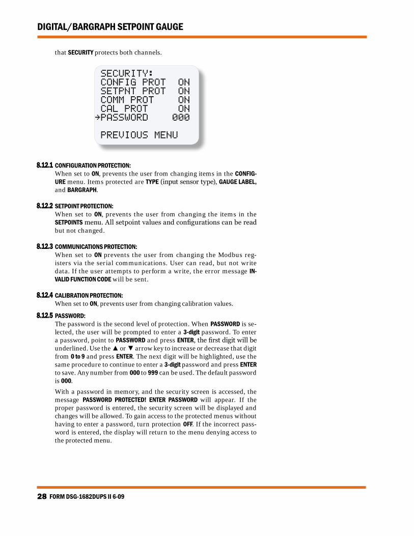
8.13 CONTROL ACTION: There are four different modes of operation on how the device operates.
They are CH1 LOOP, CH2-CH1, CH1-PID and MAPPING. These modes deter-mine how the 4-20mA is setup for this product. As these selections are saved, other values may need to be programmed as well. Use the ▲ or ▼ arrow keys to move to the field to be changed, press ENTER and the (▲▼) box will appear. The value may be increased or decreased to the new value. Press ENTER to save.
8.13.1 CH1 LOOP: To configure the CH1 LOOP, use the ▲ and ▼ arrow keys to scroll through
the selections in MODE: and press ENTER. The display will read the value for the previously set 4mA point, LOOP LOW, and 20mA point, LOOP HIGH in units the gauge is configured for. Use the ▲ or ▼ arrow keys to scroll to CH1 LOOP and press ENTER to save the new configuration.
DEADbAND 0.0 ACTION: DIRECT~MODE: CH1-PID
DEADbAND: 0.0 ACTION: DIRECT MODE: CH1 LOOP LOOP LOW ~ 400 °F LOOP HIGH 800 °F
FORM DSG-1682DUPS II 6-0930
DIGITAL/BARGRAPH SETPOINT GAUGE
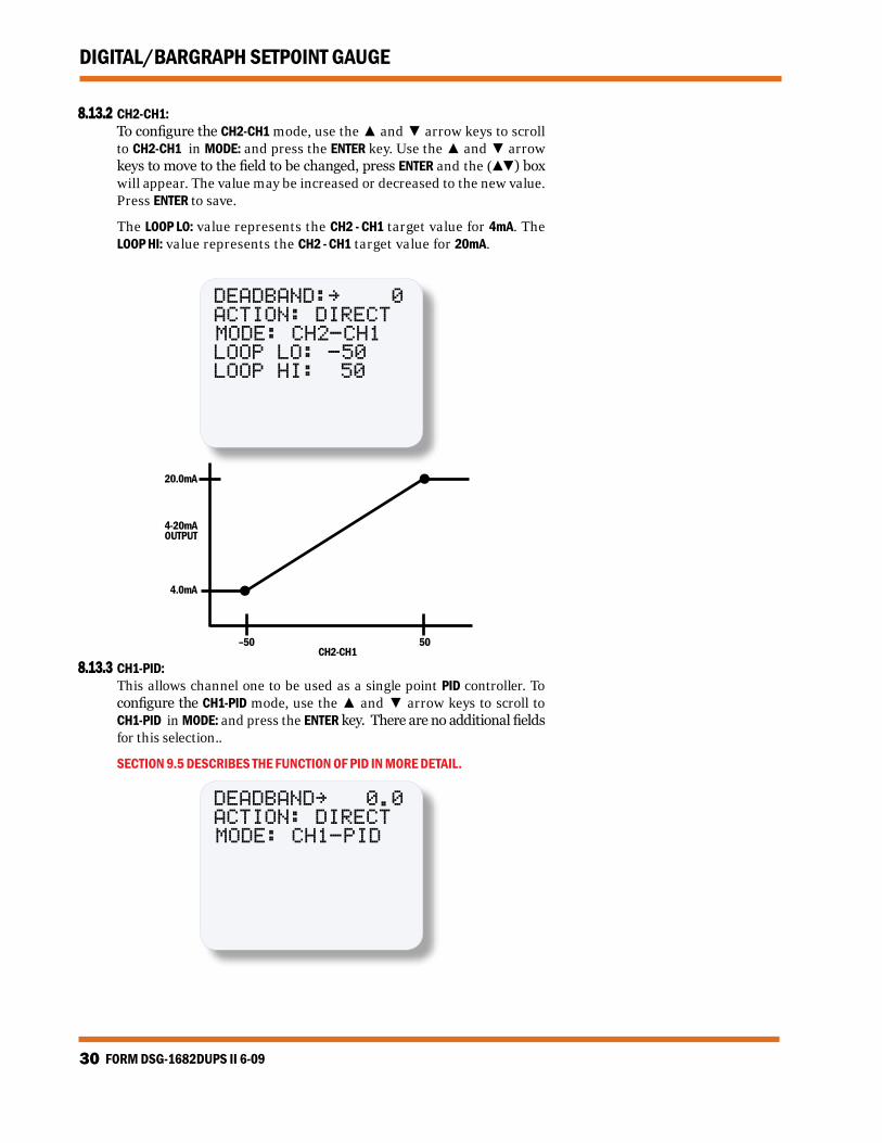
8.13.2 CH2-CH1: To configure the CH2-CH1 mode, use the ▲ and ▼ arrow keys to scroll
to CH2-CH1 in MODE: and press the ENTER key. Use the ▲ and ▼ arrow keys to move to the field to be changed, press ENTER and the (▲▼) box will appear. The value may be increased or decreased to the new value. Press ENTER to save.
The LOOP LO: value represents the CH2 - CH1 target value for 4mA. The LOOP HI: value represents the CH2 - CH1 target value for 20mA.
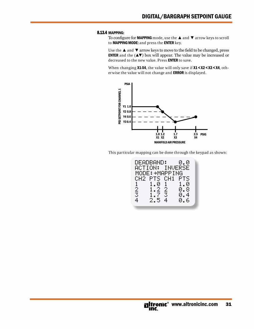
CH2-CH18.13.3 CH1-PID: This allows channel one to be used as a single point PID controller. To
configure the CH1-PID mode, use the ▲ and ▼ arrow keys to scroll to CH1-PID in MODE: and press the ENTER key. There are no additional fields for this selection..
SECTION 9.5 DESCRIBES THE FUNCTION OF PID IN MORE DETAIL.
DEADbAND~ 0.0 ACTION: DIRECT MODE: CH1-PID
www.altronicinc.com 31
DIGITAL/BARGRAPH SETPOINT GAUGE
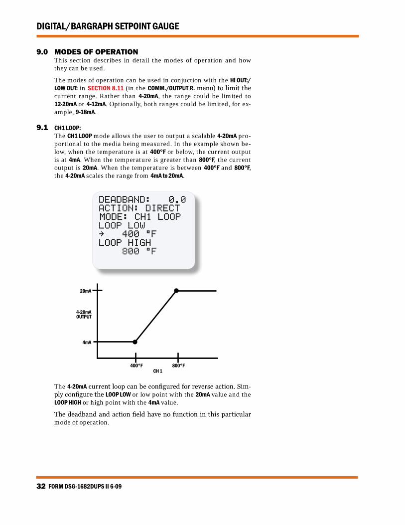
8.13.4 MAPPING: To configure for MAPPING mode, use the ▲ and ▼ arrow keys to scroll
to MAPPING MODE: and press the ENTER key.
Use the ▲ and ▼ arrow keys to move to the field to be changed, press ENTER and the (▲▼) box will appear. The value may be increased or decreased to the new value. Press ENTER to save.
When changing x1-x4, the value will only save if x1 < x2 < x3 < x4, oth-erwise the value will not change and ERROR is displayed.
Y1 1.0Y2 0.8Y4 0.6Y3 0.4
1.0x1
1.2x2
1.7x3
2.5x4
PSIG
PSIA
MANIFOLD AIR PRESSURE
PID
SETP
OINT
FOR
CHAN
NEL 1
This particular mapping can be done through the keypad as shown:
9.0 MODES OF OPERATION This section describes in detail the modes of operation and how
they can be used.
The modes of operation can be used in conjuction with the HI OUT:/LOW OUT: in SECTION 8.11 (in the COMM./OUTPUT R. menu) to limit the current range. Rather than 4-20mA, the range could be limited to 12-20mA or 4-12mA. Optionally, both ranges could be limited, for ex-ample, 9-18mA.
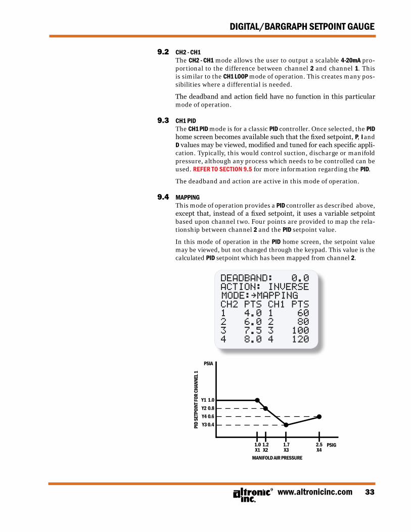
9.1 CH1 LOOP: The CH1 LOOP mode allows the user to output a scalable 4-20mA pro-
portional to the media being measured. In the example shown be-low, when the temperature is at 400°F or below, the current output is at 4mA. When the temperature is greater than 800°F, the current output is 20mA. When the temperature is between 400°F and 800°F, the 4-20mA scales the range from 4mA to 20mA.
DEADbAND: 0.0 ACTION: DIRECT MODE: CH1 LOOP LOOP LOW ~ 400 °F LOOP HIGH 800 °F
20mA
4mA
400°F 800°F
4-20mAOUTPUT
CH 1
The 4-20mA current loop can be configured for reverse action. Sim-ply configure the LOOP LOW or low point with the 20mA value and the LOOP HIGH or high point with the 4mA value.
The deadband and action field have no function in this particular mode of operation.
www.altronicinc.com 33
DIGITAL/BARGRAPH SETPOINT GAUGE
9.2 CH2 - CH1 The CH2 - CH1 mode allows the user to output a scalable 4-20mA pro-
portional to the difference between channel 2 and channel 1. This is similar to the CH1 LOOP mode of operation. This creates many pos-sibilities where a differential is needed.
The deadband and action field have no function in this particular mode of operation.
9.3 CH1 PID The CH1 PID mode is for a classic PID controller. Once selected, the PID
home screen becomes available such that the fixed setpoint, P, I and D values may be viewed, modified and tuned for each specific appli-cation. Typically, this would control suction, discharge or manifold pressure, although any process which needs to be controlled can be used. REFER TO SECTION 9.5 for more information regarding the PID.
The deadband and action are active in this mode of operation.
9.4 MAPPING This mode of operation provides a PID controller as described above,
except that, instead of a fixed setpoint, it uses a variable setpoint based upon channel two. Four points are provided to map the rela-tionship between channel 2 and the PID setpoint value.
In this mode of operation in the PID home screen, the setpoint value may be viewed, but not changed through the keypad. This value is the calculated PID setpoint which has been mapped from channel 2.
As the field pressure decreases, the control setpoint for the dis-charge pressure decreases. In this application, the engine continues to run and prevents the well from running dry.
The deadband and action are active in this mode of operation. 9.5 PID CONTROL/OVERVIEW: A PID controller is a common controller used in many industrial con-
trol systems. A full description of PID control and theory is beyond the scope of this manual. However, there are many good web resources which can be viewed for more understanding.
The PID algorithm takes the difference between the control setpoint (value to control to) and the measured value (what is actually dis-played) and makes a corrective action (by modifying the 4-20mA) to achieve the control setpoint.
9.5.1 DEADBAND: The controller deadband defines a user programmed value both
above and below the setpoint for which no corrective action will be taken. Deadband is used to improve control stability by holding the controller output constant in the presence of “noise” or small tran-sient errors on the input.
This function only has meaning in the PID mode of operation.
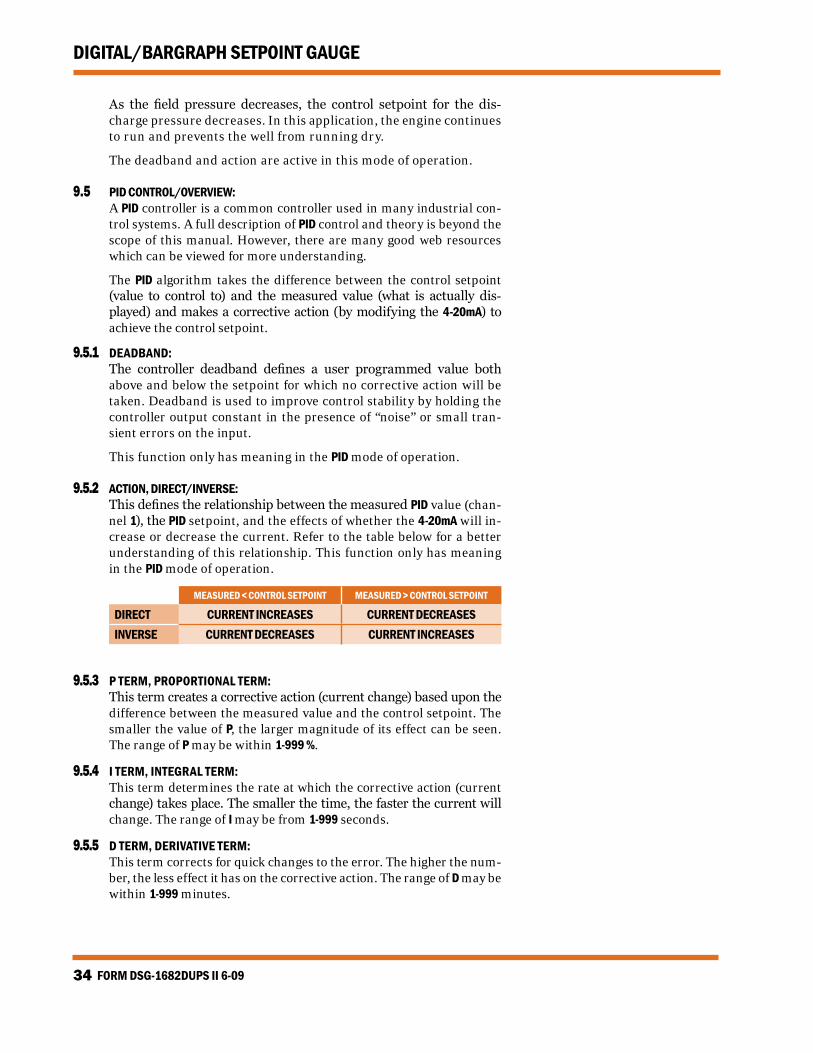
9.5.2 ACTION, DIRECT/INVERSE: This defines the relationship between the measured PID value (chan-
nel 1), the PID setpoint, and the effects of whether the 4-20mA will in-crease or decrease the current. Refer to the table below for a better understanding of this relationship. This function only has meaning in the PID mode of operation.
MEASURED < CONTROL SETPOINT MEASURED > CONTROL SETPOINT
DIRECT CURRENT INCREASES CURRENT DECREASES INVERSE CURRENT DECREASES CURRENT INCREASES
9.5.3 P TERM, PROPORTIONAL TERM: This term creates a corrective action (current change) based upon the
difference between the measured value and the control setpoint. The smaller the value of P, the larger magnitude of its effect can be seen. The range of P may be within 1-999 %.
9.5.4 I TERM, INTEGRAL TERM: This term determines the rate at which the corrective action (current
change) takes place. The smaller the time, the faster the current will change. The range of I may be from 1-999 seconds.
9.5.5 D TERM, DERIVATIVE TERM: This term corrects for quick changes to the error. The higher the num-
ber, the less effect it has on the corrective action. The range of D may be within 1-999 minutes.
www.altronicinc.com 35
DIGITAL/BARGRAPH SETPOINT GAUGE
9.5.6 AUTO/MANUAL MODE This allows the PID control to be in either AUTO or MANUAL mode of op-
eration. In the AUTO mode, the instrument automatically performs PID functions. In MANUAL mode, the 4-20mA remains at its current value. The current may be manually changed as described in the next section.
9.5.7 C/CHANGE CURRENT This field allows the user to increment or decrement the 4-20mA current if
the unit is in the MANUAL mode. Place the right arrow by the “C” and press ENTER. Press the ▲ and ▼ arrow keys to increase or decrease the current.
FORM DSG-1682DUPS II 6-0936
DIGITAL/BARGRAPH SETPOINT GAUGE
10.0 RS-485 COMMUNICATIONS The DSG-1682DUPS gauge is part of a system that has been carefully
designed to easily interface to popular computers, terminals, pro-grammable controllers and Altronic instruments. The gauge com-municates in the Modbus RTU protocol.
10.1 MASTER/SLAVE OPERATION: (FIG. 19) The gauge’s RS-485 communication system is designed as a master/
slave system; that is, each unit responds to its own unique address (node number) only after it is interrogated by the master (comput-er). One master and up to 32 slaves can communicate in the sys-tem. The units communicate with the master via a polling system. The master sends a command and only the polled slave responds. The slave modules can never initiate a communications sequence. A simple command/response protocol must be strictly observed.
10.2 NODE NUMBER: The node number is used in the system to identify the desired slave
unit being polled. The node number can be any numeric value from 1 to 99 although only 32 devices can be served on a single communi-cations port. This number range (1 to 99) is allowed so that if device grouping by function or application is desired, it can be implement-ed using the first digit as the group or engine number and the sec-ond as the unit number. For example, 53 could be used to identify the number 3 slave unit mounted on engine number 5.
10.3 BAUD RATE: Baud rates available are 9600, 19200, 38400, 57600, 115200.
10.4 HALF-DUPLEx OPERATION: The RS-485 system employed uses two wires for communication and
cannot send and receive data at the same time over the same two wires making it a half-duplex system. When the master is in the transmit mode, the slave is in the receive mode and vice-versa.
10.5 ELECTRICAL OPERATING RANGE: RS-485 is a communications standard to satisfy the need for multi-
dropped systems that can operate at high speeds over long distances. RS-485 uses a balanced differential pair of wires switching from 0 to 5 volts to communicate data. RS-485 drivers can handle common mode voltages from -7 to +12 volts without loss of data, making them an excellent choice for industrial environments.
10.6 COMMUNICATIONS PARAMETERS: The following must be set by the master to communicate with the slaves:
10.7 COMMUNICATIONS WIRING: The RS-485 wiring diagram (FIG. 19) illustrates the wiring required
for multiple slave unit hookup. Note that every slave unit has a di-rect connection to the master. This allows any one slave unit to be removed from service without affecting the operation of the other
www.altronicinc.com 37
DIGITAL/BARGRAPH SETPOINT GAUGE
units. Every unit must be programmed with a unique address or node number, but the addition of new units or nodes can be in any order. To minimize unwanted reflections on the transmission line, the bus should be arranged as a trunk line going from one module to the next. Random structures of the transmission line should be avoided. Spe-cial care must be taken with long busses (500 feet or more) to ensure error-free operation. Long busses must be terminated with a 120 ohm resistor between the terminals marked RS-485 A and RS-485 B at the master only. The use of twisted pair shielded cable will enhance sig-nal fidelity and is recommended. To prevent ground loops the shield should be connected to the shield terminal at the master only.
10.8 Rx, Tx INDICATORS: Rx and Tx (receive and transmit) LEDs on the back of the gauge indicate
when the unit is receiving or transmitting data.
10.9 CONNECTING TO A PC: When connecting the gauge to the RS-232 port on a PC, an RS-232
to RS-485 converter (FIG. 18) must be used for the communication interface.
10.10 LOADING: RS-485 uses a balanced differential pair of wires switching from 0 to
5 volts to communicate data. In situations where many units (32 max.) are connected together on a long run, voltage drop on the communi-cations leads becomes a major problem. Voltage drops on the RS-485 minus lead appear as a common mode voltage to the receivers. While the receivers are rated to a maximum voltage difference of ±7 volts, -7V to +12V, a practical system should not have a voltage difference exceeding ±3 volts under normal conditions. The wire gauge used for the connec-tions, therefore, limits the maximum number of units or the maximum length of wire between units in each application. The following for-mula can be used as a guideline to select the appropriate wire gauge.
• For 18 AWG wire No. of units = (4000)/(ft. of wire used) • For 20 AWG wire No. of units = (2500)/(ft. of wire used) • For 22 AWG wire No. of units = (1600)/(ft. of wire used)
NOTE: The maximum num-ber of units connected in a system is 32.
FORM DSG-1682DUPS II 6-0938
DIGITAL/BARGRAPH SETPOINT GAUGE
11.0 MODBUS REGISTER LISTS: The maximum number of registers that can be read at one time is
limited to 32. The maximum number of booleans that can be read at one time is limited to 256. All communications are at 9600 baud (default), SEE SECTION 10.3 FOR OTHER SPEEDS 8 Data bits, No Parity, 1 Stop bit (9600 8N1).
11.1 00000 SERIES REGISTERS
ADDRESS DESCRIPTION OF FUNCTION00001 PROTECT CONFIGURATION 0=OFF 1=ON
Protect configuration from being changed by keypad00002 PROTECT SETPOINT 0=OFF 1=ON
Protect setpoints from being changed by keypad00003 PROTECT COMMUNICATIONS 0=OFF 1=ON
Protect against ModBus writes00004 PROTECT CALIBRATION 0=OFF 1=ON
00048 Config Override – Allow ModBus to override Channel Configuration
Note: All temperatures are stated in 0.1 DEG. Kelvin (for universal compatibility). Therefore a register value of 2730 is 273.0° K, which is 0° C, or 32°F.
www.altronicinc.com 39
DIGITAL/BARGRAPH SETPOINT GAUGE
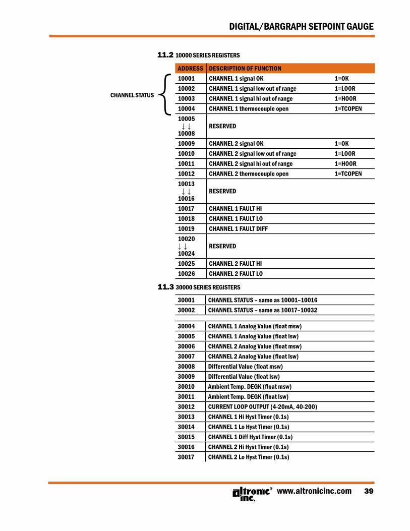
ADDRESS DESCRIPTION OF FUNCTION10001 CHANNEL 1 signal OK 1=OK10002 CHANNEL 1 signal low out of range 1=LOOR10003 CHANNEL 1 signal hi out of range 1=HOOR10004 CHANNEL 1 thermocouple open 1=TCOPEN10005 ↓ ↓10008
RESERVED
10009 CHANNEL 2 signal OK 1=OK10010 CHANNEL 2 signal low out of range 1=LOOR10011 CHANNEL 2 signal hi out of range 1=HOOR10012 CHANNEL 2 thermocouple open 1=TCOPEN10013 ↓ ↓10016
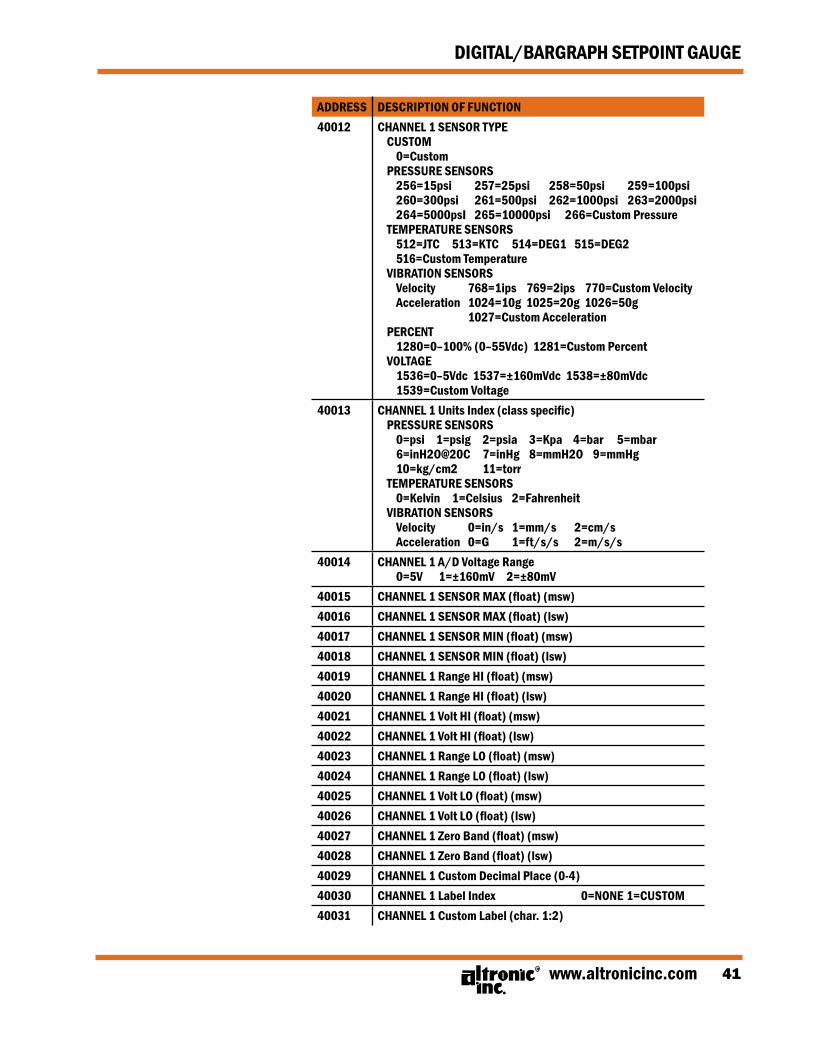
40014 CHANNEL 1 A/D Voltage Range 0=5V 1=±160mV 2=±80mV
40015 CHANNEL 1 SENSOR MAX (float) (msw)40016 CHANNEL 1 SENSOR MAX (float) (lsw)40017 CHANNEL 1 SENSOR MIN (float) (msw)40018 CHANNEL 1 SENSOR MIN (float) (lsw)40019 CHANNEL 1 Range HI (float) (msw)40020 CHANNEL 1 Range HI (float) (lsw)40021 CHANNEL 1 Volt HI (float) (msw)40022 CHANNEL 1 Volt HI (float) (lsw)40023 CHANNEL 1 Range LO (float) (msw)40024 CHANNEL 1 Range LO (float) (lsw)40025 CHANNEL 1 Volt LO (float) (msw)40026 CHANNEL 1 Volt LO (float) (lsw)40027 CHANNEL 1 Zero Band (float) (msw)40028 CHANNEL 1 Zero Band (float) (lsw)40029 CHANNEL 1 Custom Decimal Place (0-4)40030 CHANNEL 1 Label Index 0=NONE 1=CUSTOM40031 CHANNEL 1 Custom Label (char. 1:2)
0=Off 1=Single bar between low and high 2=Increasing bars between low and high 3=Single bar between setpoints for switch 1 4=Increasing bars between setpoints for switch 1
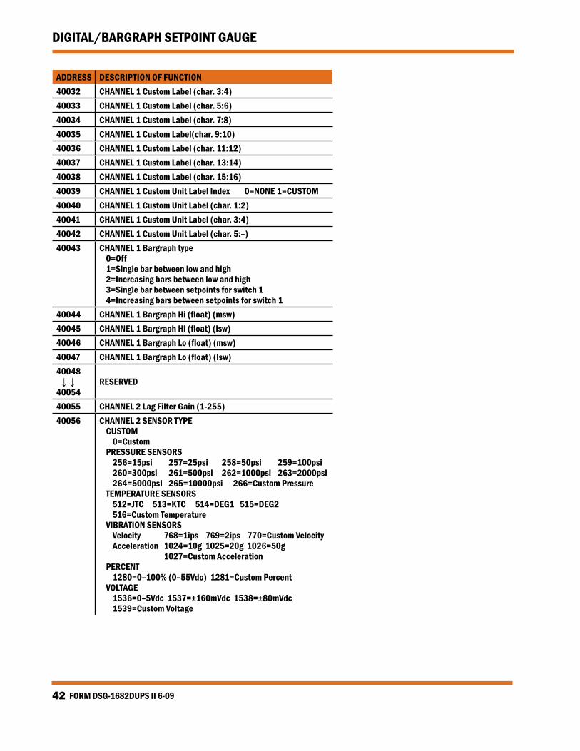
40044 CHANNEL 1 Bargraph Hi (float) (msw)40045 CHANNEL 1 Bargraph Hi (float) (lsw)40046 CHANNEL 1 Bargraph Lo (float) (msw)40047 CHANNEL 1 Bargraph Lo (float) (lsw)40048 ↓ ↓40054
RESERVED
40055 CHANNEL 2 Lag Filter Gain (1-255)40056 CHANNEL 2 SENSOR TYPE
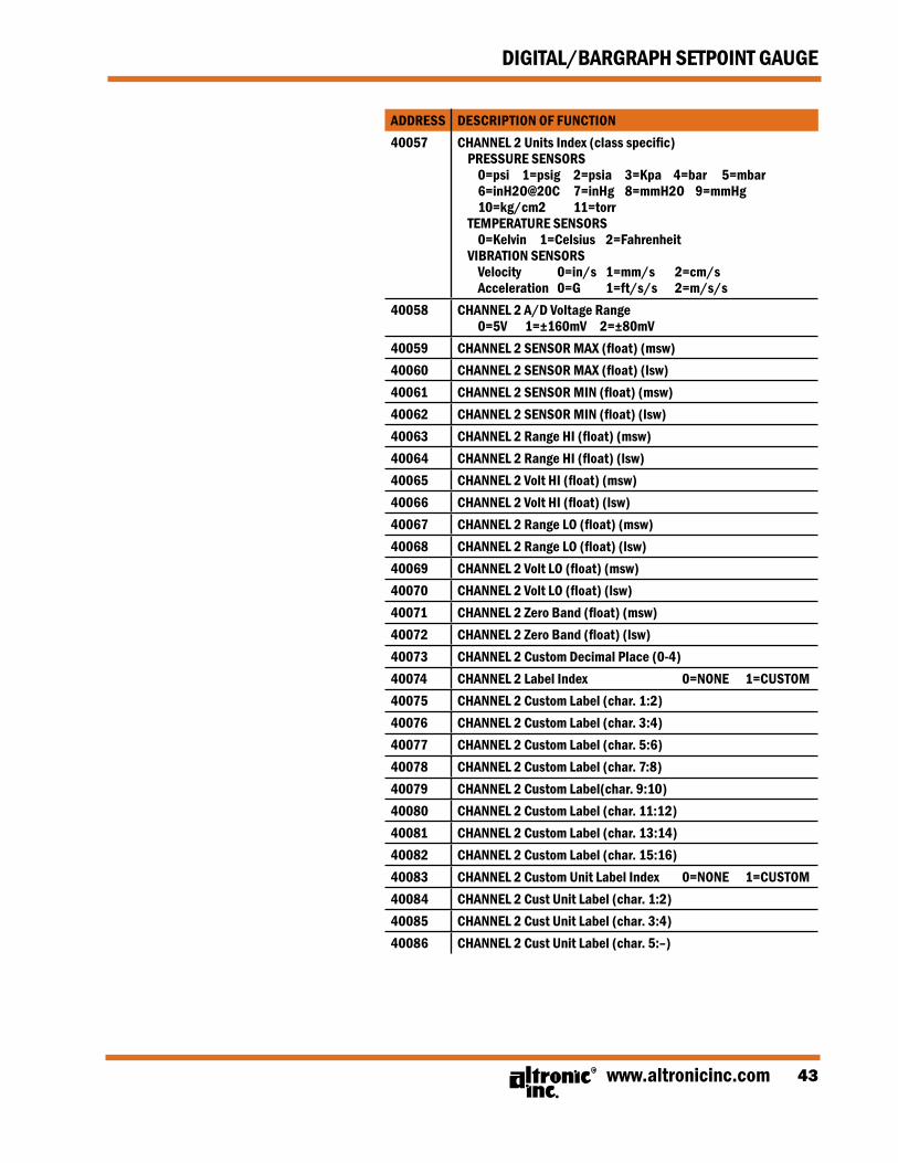
40058 CHANNEL 2 A/D Voltage Range 0=5V 1=±160mV 2=±80mV
40059 CHANNEL 2 SENSOR MAX (float) (msw)40060 CHANNEL 2 SENSOR MAX (float) (lsw)40061 CHANNEL 2 SENSOR MIN (float) (msw)40062 CHANNEL 2 SENSOR MIN (float) (lsw)40063 CHANNEL 2 Range HI (float) (msw)40064 CHANNEL 2 Range HI (float) (lsw)40065 CHANNEL 2 Volt HI (float) (msw)40066 CHANNEL 2 Volt HI (float) (lsw)40067 CHANNEL 2 Range LO (float) (msw)40068 CHANNEL 2 Range LO (float) (lsw)40069 CHANNEL 2 Volt LO (float) (msw)40070 CHANNEL 2 Volt LO (float) (lsw)40071 CHANNEL 2 Zero Band (float) (msw)40072 CHANNEL 2 Zero Band (float) (lsw)40073 CHANNEL 2 Custom Decimal Place (0-4)40074 CHANNEL 2 Label Index 0=NONE 1=CUSTOM40075 CHANNEL 2 Custom Label (char. 1:2)40076 CHANNEL 2 Custom Label (char. 3:4)40077 CHANNEL 2 Custom Label (char. 5:6)40078 CHANNEL 2 Custom Label (char. 7:8)40079 CHANNEL 2 Custom Label(char. 9:10)40080 CHANNEL 2 Custom Label (char. 11:12)40081 CHANNEL 2 Custom Label (char. 13:14)40082 CHANNEL 2 Custom Label (char. 15:16)40083 CHANNEL 2 Custom Unit Label Index 0=NONE 1=CUSTOM40084 CHANNEL 2 Cust Unit Label (char. 1:2)40085 CHANNEL 2 Cust Unit Label (char. 3:4)40086 CHANNEL 2 Cust Unit Label (char. 5:–)
FORM DSG-1682DUPS II 6-0944
DIGITAL/BARGRAPH SETPOINT GAUGE
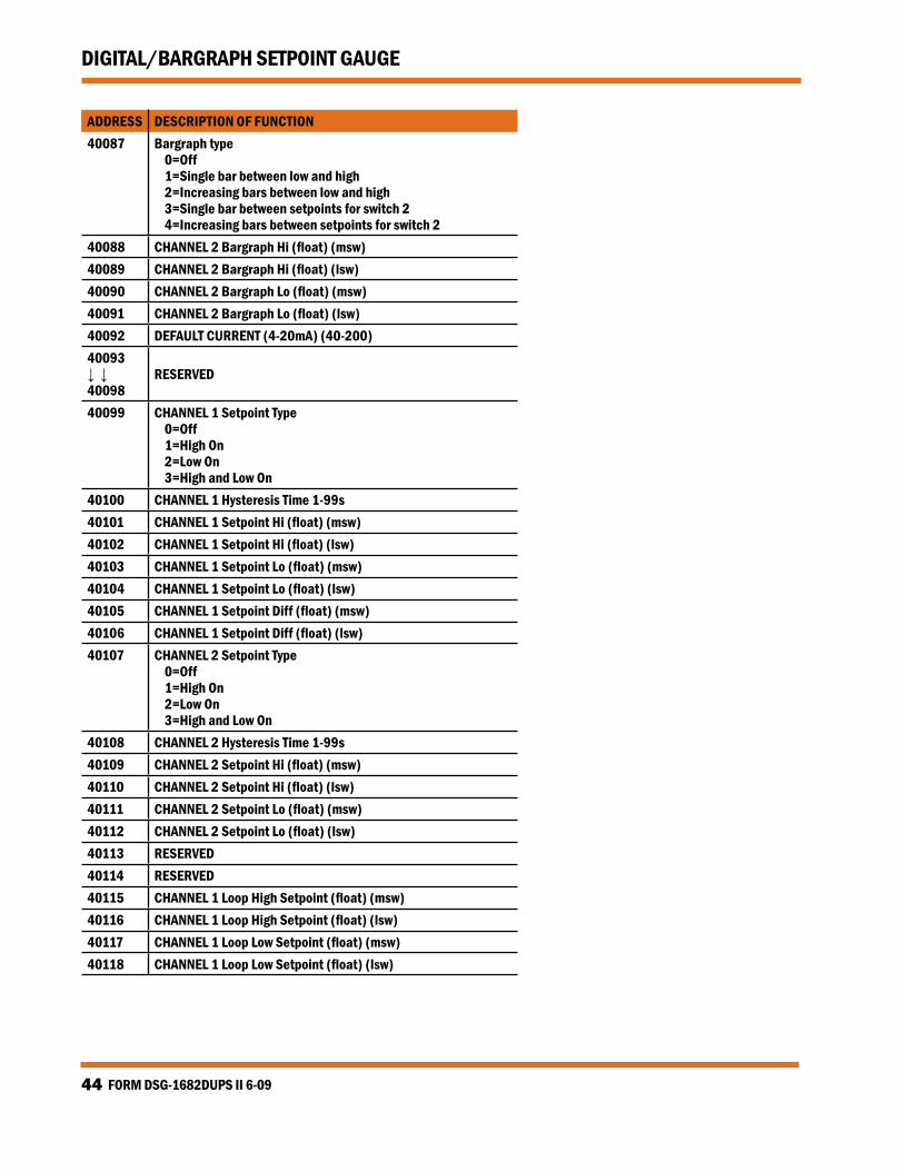
ADDRESS DESCRIPTION OF FUNCTION40087 Bargraph type
0=Off 1=Single bar between low and high 2=Increasing bars between low and high 3=Single bar between setpoints for switch 2 4=Increasing bars between setpoints for switch 2
40088 CHANNEL 2 Bargraph Hi (float) (msw)40089 CHANNEL 2 Bargraph Hi (float) (lsw)40090 CHANNEL 2 Bargraph Lo (float) (msw)40091 CHANNEL 2 Bargraph Lo (float) (lsw)40092 DEFAULT CURRENT (4-20mA) (40-200)40093 ↓ ↓40098
RESERVED
40099 CHANNEL 1 Setpoint Type 0=Off 1=High On 2=Low On 3=High and Low On
40100 CHANNEL 1 Hysteresis Time 1-99s40101 CHANNEL 1 Setpoint Hi (float) (msw)40102 CHANNEL 1 Setpoint Hi (float) (lsw)40103 CHANNEL 1 Setpoint Lo (float) (msw)40104 CHANNEL 1 Setpoint Lo (float) (lsw)40105 CHANNEL 1 Setpoint Diff (float) (msw)40106 CHANNEL 1 Setpoint Diff (float) (lsw)40107 CHANNEL 2 Setpoint Type
0=Off 1=High On 2=Low On 3=High and Low On
40108 CHANNEL 2 Hysteresis Time 1-99s40109 CHANNEL 2 Setpoint Hi (float) (msw)40110 CHANNEL 2 Setpoint Hi (float) (lsw)40111 CHANNEL 2 Setpoint Lo (float) (msw)40112 CHANNEL 2 Setpoint Lo (float) (lsw)40113 RESERVED 40114 RESERVED40115 CHANNEL 1 Loop High Setpoint (float) (msw)40116 CHANNEL 1 Loop High Setpoint (float) (lsw)40117 CHANNEL 1 Loop Low Setpoint (float) (msw)40118 CHANNEL 1 Loop Low Setpoint (float) (lsw)
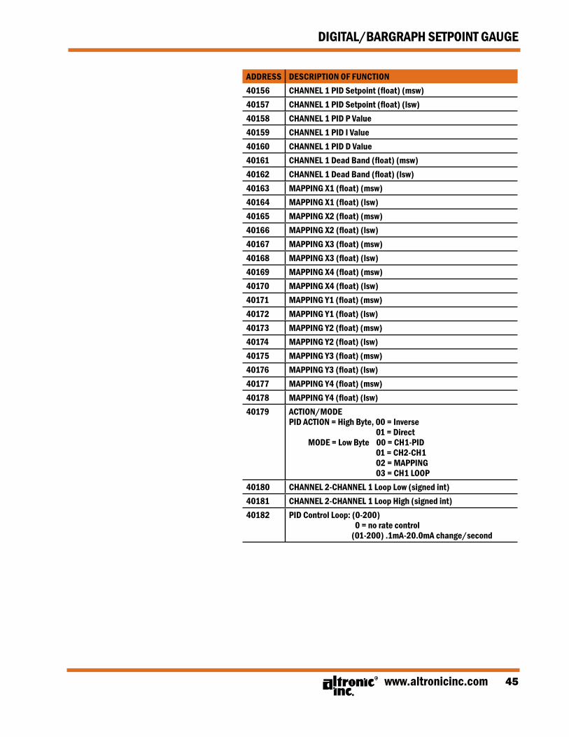
40180 CHANNEL 2-CHANNEL 1 Loop Low (signed int)40181 CHANNEL 2-CHANNEL 1 Loop High (signed int)40182 PID Control Loop: (0-200)
0 = no rate control (01-200) .1mA-20.0mA change/second
FORM DSG-1682DUPS II 6-0946
DIGITAL/BARGRAPH SETPOINT GAUGE
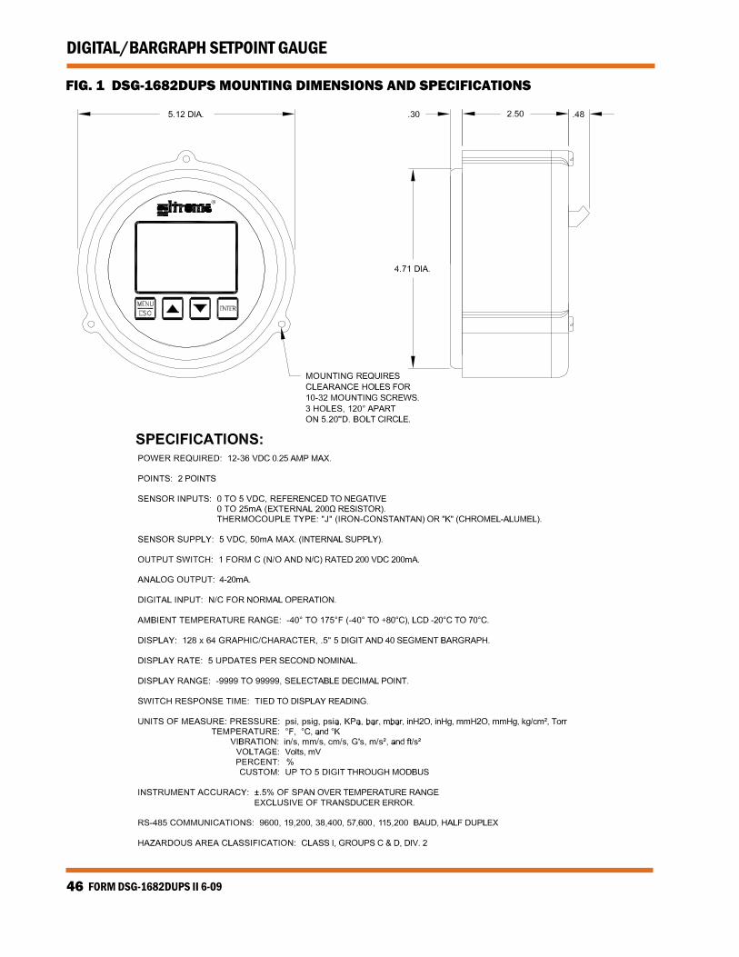
FIG. 1 DSG-1682DUPS MOUNTING DIMENSIONS AND SPECIFICATIONS
www.altronicinc.com 47
DIGITAL/BARGRAPH SETPOINT GAUGE
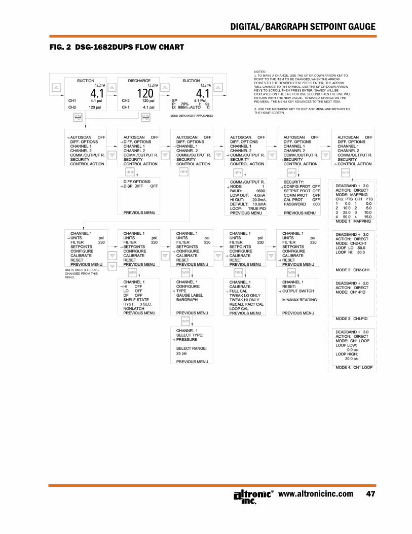
FIG. 2 DSG-1682DUPS FLOW CHART
FLOWCHART, DSG-1682DUPS
12.2mA
4.112.2mA
12012.2mA
4.1
NOTES:1. TO MAKE A CHANGE, USE THE UP OR DOWN ARROW KEY TOPOINT TO THE ITEM TO BE CHANGED, WHEN THE ARROWPOINTS TO THE DESIRED ITEM, PRESS ENTER, THE ARROWWILL CHANGE TO ( ) SYMBOL, USE THE UP OR DOWN ARROWKEYS TO SCROLL THEN PRESS ENTER, "SAVED" WILL BEDISPLAYED ON THE LINE FOR ONE SECOND THEN THE LINE WILLRETURN WITH THE NEW VALUE. TO MAKE A CHANGE ON THEPID MENU, THE MENU KEY ADVANCES TO THE NEXT ITEM.
2. USE THE MENU/ESC KEY TO EXIT ANY MENU AND RETURN TOTHE HOME SCREEN.