55
Chapter 3 ydraulic Control Valve
| Date post: | 11-Feb-2016 |
| Category: |
Documents |
| Upload: | balakrishnan |
| View: | 17 times |
| Download: | 0 times |

Chapter 3Hydraulic Control Valves

Hydraulic Control Valves
Directional
Control Valves
Flow
Control Valves
Pressure
Control Valves

A pressure control valve can be used :
1-To limit the maximum pressure
2-To set a back pressure
3-To pass a signal when a certain pressure is reached
4- To protect the pump from over pressure
3- Pressure Control Valves

Seven pressure-control valves will be discussed. These valves are:
1. Relief valves
2. Unloading valves
3. Sequence valves
4. Pressure-reducing valves
5. Counterbalance valves
6. Safety Valve
Types of Pressure Control Valves
Each of these valves works on the same principle;
a spring force balances a hydraulic force.
The hydraulic force is produced by pressure acting on a given area. When the
hydraulic force becomes greater than the spring force, the valve spool moves.

1- Pressure Relief Valve (PRV)
Its function is to set the maximum pressure in the hydraulic system.
The pressure can rise in a hydraulic system if:
1- The flow rate from the pump is larger than the flow rate through the
actuator
2- The volume of a closed system is reduced
3- The load of the actuator rises
4- The hydraulic resistance of the system rises
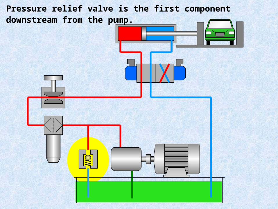
Pressure relief valve is the first component downstream from the pump.

Complete Circuit

Pressure Relief Valve
Direct Acting Relief Valve
Pilot OperatedRelief Valve

1 -Direct Acting Relief Valve


تصريف صمامات تصممالصمام الضغطفىشكل
المنزلق , الصمام او القفازيضغط دائما الياى ويكون
القفل قطعةالسائل دخول فتحة الى
للصمام
من : الصمام يتكونالصمام - 1 جسممخروط ( / / - 2 كرة القفل قطعة
)قرص
احكام - 3 ياىرجالش ( )- 4 الضبط وعجلة مسمارالسائل - 5 دخول P فتحة
للخزان - 6 السائل تدفق Tفتحة
1 -Direct Acting Relief Valve
( الصمام( تكوين )PRV(أ
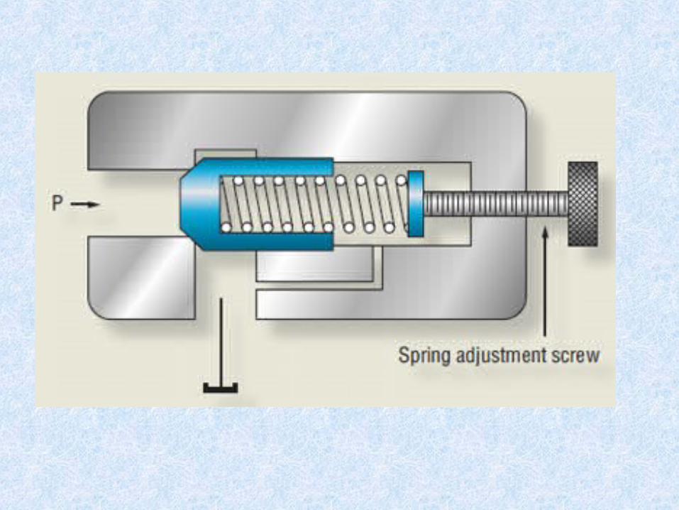

يكون بدءعند - 1 الدورة تشغيلمقطع Pالضغط علىمساحة المؤثر
القفل للضغط صغيرقطعة بالنسبةعليه عنه الصمامالمضبوط فينتج
الياى , صغيرة Fhقوة دفع قوة وتكونFs القفل تبقى, اكبر لقطعة لذا
القفل لفتحة محكمة قطعة الغلقالعلوGى دخول الشكل فى كما السائل
.
Fs > Fh
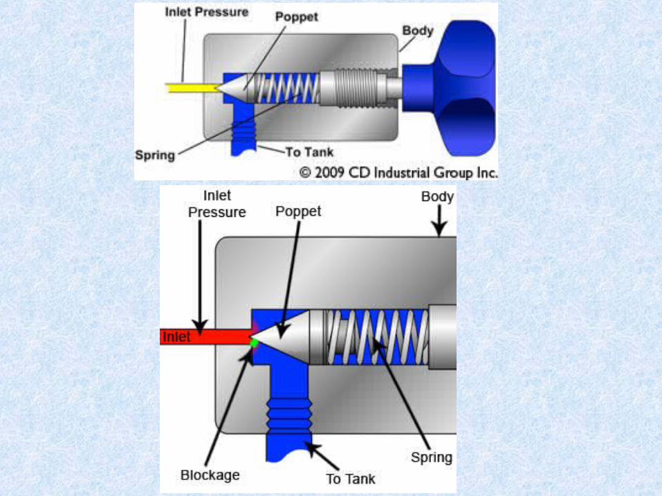
الضغط - 2 عن الدورة ضغط بزيادةالقوة تصبح اكبرللسائل Fhالمحدد
الياى دفع قوة قطعة Fsمن فتتحركالياى قوة للخلفضد لتفتحالقفل
الى يتدفقو الدخولفتحة السائلفتحة الخزان فى الخروجمن كما
السفلى . الشكل Fs < Fh
الصمام (ب) عمل )PRV( نظرية

(a) Closed Relief Valve (b) Opened Relief Valve


400litres/min
= 7 tonne350 bar x 1960 mm2 = 70,000 N
350 bar 50 mm
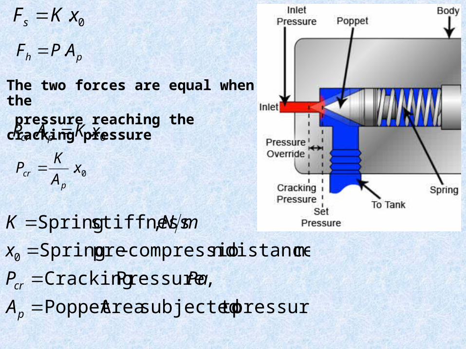
0.xKFs
ph APF .
The two forces are equal when the pressure reaching the cracking pressure
0.. xKAP pcr
0.xAKPp
cr
pressure tosubjected AreaPoppet Pressure, Cracking
m distance,n compressio-pre Spring ,stiffness Spring
0
p
cr
APaP
xmNK


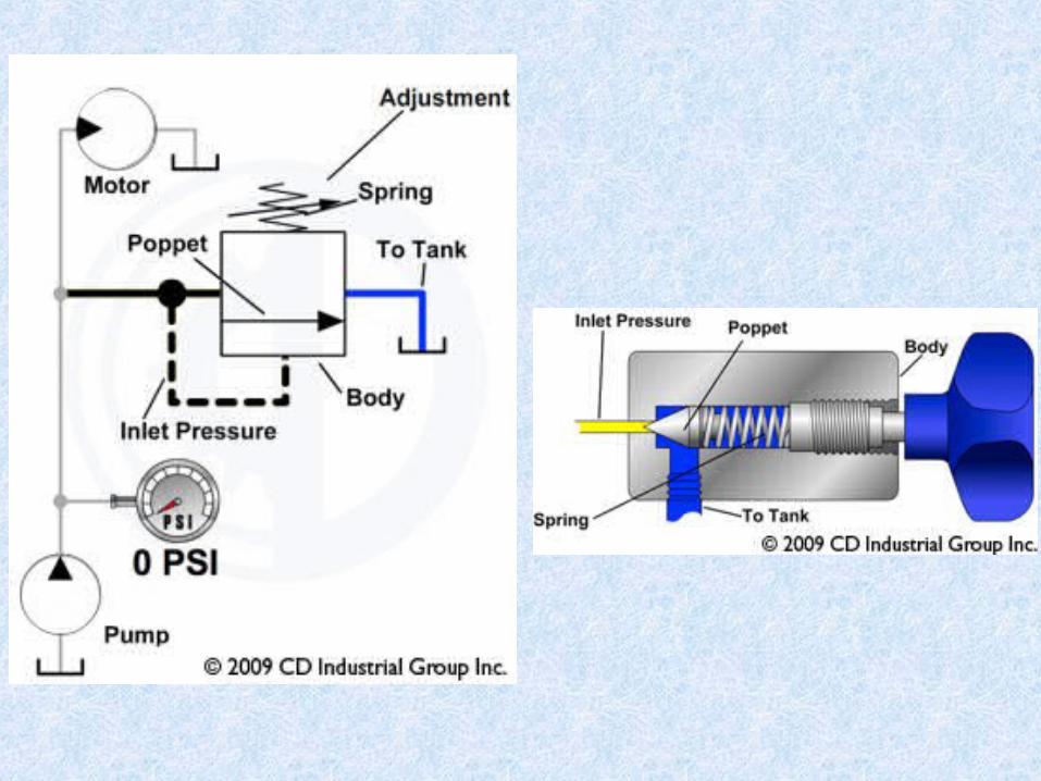
Pressure acts on the annular area of the valve spool. The hydraulic force is given by
1- When Fh equals F s , the valve remain closed.
2- When pressure increases, the spool lifts higher, allowing more flow to
bypass to the reservoir.
3- At some pressure level, the total flow bypasses to the reservoir.
ah APF .
Aa = Annulus Area

Typical flow vs. pressure curve for a direct-acting relief valve.
Direct Relief Valve Performance

1- The valve is set to open at 1500 psi. This pressure is known as the
cracking pressure.
2-When pressure reaches 2000 psi, the valve is fully open, and all flow is
bypassed to the reservoir; no flow goes to the remainder of the circuit.
3- The 500 psi differential between cracking and full bypass is needed for a
direct-acting valve when it has a functional role in flow control in
addition to its pressure limiting function.
4- This differential between cracking and full bypass is called
override pressure.
Override Pressure = 2000 – 1500 = 500 Psi

Circuit in which motor speed is controlled with a flow control valve
1- Pressure at the relief valve is the sum of the pressure drop across the flow
control valve plus the pressure drop across the motor.
2- To slow the motor, the flow control valve is closed to create enough pressure at
the relief valve to cause it to crack open.
3- Part of the pump output now bypasses to the reservoir; thus, flow to the motor
is reduced, and the speed decreases.
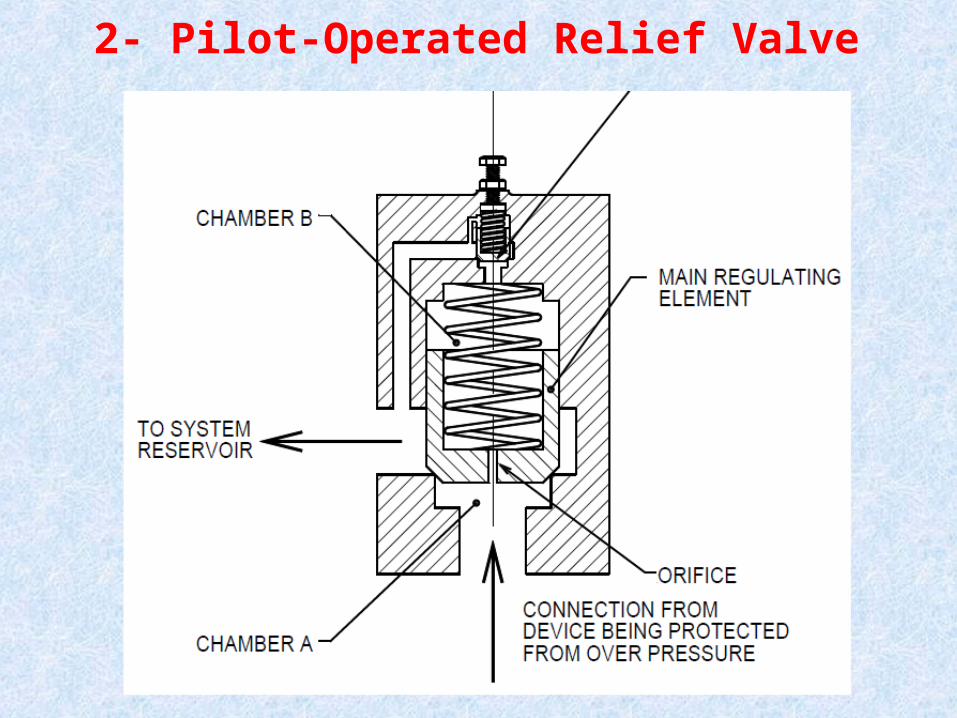
2- Pilot-Operated Relief Valve

• The pilot element can be quite small because this pilot is only required to
pass a small flow.
• During the normal closed condition of the valve, there is no flow through
the orifice in the main regulating element, so there is no pressure difference
across the main element. Thus the main element can be held in a closed
position by a light spring.
• As the pressure in chamber A increases, the pressure downstream of the
orifice matches this pressure until the pilot valve opens and there is flow to
the system reservoir.
• Now that there is flow through the orifice in the main regulating element,
a pressure difference will be developed across the orifice. As indicated
earlier, the spring controlling the main regulating element is light, so only a
small pressure difference is required to move the main regulating element
into its open position.

• With flow through the valve, there must be sufficient pressure in chamber
B to keep the pilot valve open.
• Thus the pressure in chamber A must exceed the pressure in chamber
B by a small amount. The amount being the pressure drop across the orifice
in the main regulating element.
• Because the main element is controlled by a light spring, the operating
pressure is only a small amount above the pressure at which the pilot valve
cracked.
• Consequently the pressure required to open a pilot operated valve is much
less dependent on the flow through the valve than is the situation
with a direct acting valve.


Comparison of performance curves for direct-acting and pilot-operated relief valves.

1- A pilot-operated relief valve has the same function as a direct-acting
relief valve; however, it has a different pressure vs. flow curve.
2- The pilot-operated valve opens completely over a narrow pressure
range.
3- This allows the circuit to operate over a wider pressure range without
loss of fluid over the relief valve.
The key advantage of a pilot-operated valve is that it allows the designer
to use pressure to within 100 psi of the valve setting to meet the
functional objective of the circuit. In comparison, the direct-acting valve
cracks open at 1500 psi, and pressure must increase to 2000 psi before it
is fully open.

2- Unloading ValveThe symbol for an unloading valve is similar to the symbol for a relief
valve except that the pilot line is not connected to sense pressure at the
valve inlet.
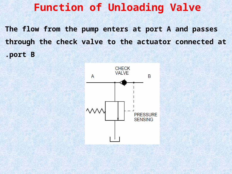
Function of Unloading Valve
The flow from the pump enters at port A and passes through the check
valve to the actuator connected at port B.

The desired function of such a circuit would be to actuate the cylinder until the item is
held and the pressure in the system rises to some value considered adequate for the
clamping force.At this juncture, no work is being done by the cylinder, so ideally no power should be
delivered to the pump supplying the cylinder. The desired pressure is sensed by the
feedback line downstream of the check valve (port B).The unloading valve now opens and flow from the pump can pass through the valve to the
reservoir across a low pressure .

Circuit Using Unloading Valve
The circuit is sometimes referred to as a fast approach, slow-feed circuit.

1- The valve is put to good use in a system where a large flow volume is
needed at a lower pressure, and then later, a very low flow volume is
required with a higher pressure.
2- Two pumps, plumbed in parallel, are used in such a circuit.
One fixed displacement pump provides volume for the lower pressure, high
flow mode, while a small pump provides the low flow at the higher
pressure.
3- The purpose of using the two pumps is to save energy draw at the prime
movers during the long periods when the only function of the hydraulic
system is to maintain an even maximum pressure with very little or no
flow.
4- When the system cylinders are extending quickly at low pressure (any
pressure below the setting of the unloading valve), both pumps send their
full volume into the cylinder.

When the cylinders encounter enough mechanical resistance to bring the system
pressure up to the setting of the unloading valve, the high flow volume pump is
directed to tank through the piloted unloading valve.

The volume of the smaller pump cannot escape to tank through the unloading
valve due the check valve in the system. The presence of the check valve makes
the schematic symbol for the unloading valve distinct from a typical relief valve.

As the cylinder continues to move against resistance (system pressure) that is
higher than the unloading valve setting, the motion is slower as only the volume
from the small pump is available.

3- Sequence Valve
sequence valve is a normally closed valve with pilot line to sense inlet pressure
The sequence valve is used to ensure that a certain pressure level is achieved
in one branch of the circuit before a second branch is activated.This valve is externally drained, meaning that there is a separate line from the
valve back to the reservoir
مسار بفتح الضGغط تصريف صمام يسمح
الى اخر (جزءللسائل يراد) تالىهيدروليكى
عند معين تشغيله يعمل , ضغط حيث للدورة
يصل ان الى تصريفعادى كصمام الصمام
مكبس امام الخارجى الضغط الى التشغيل
المطلوب فتحهضغط الضغط يساوى الذى
التالية الدورة لتشغيل

Consider a machining operation where the workpiece must be clamped with a
certain force before it is extended to make contact with the cutting tool.
The valve sensing the pressure before it
Circuit Using Sequence Valve

1- The sequence valve is set on 600 psi, meaning that pressure must
build to 600 psi before the valve opens.
2- This setting ensures that the clamp cylinder exerts a 600-psi clamp
force before the extend cylinder moves.
3- Proper sizing of the cylinders will minimize energy loss in a sequence
valve circuit.
4- Suppose the maximum pressure to extend the workpiece is 400 psi.
Pressure drop across the sequence valve is 600 − 400 = 200 psi.

4- Pressure-Reducing ValveIn some situations, two or more pressures are required in different parts
of a circuit, but only one pump is specified to keep costs down.Pressure-reducing valve is a normally open valve with pilot line to sense
outlet pressure
This valve is externally drained,
meaning that there is a separate line
from the valve back to the reservoir

A pressure-reducing valve does not allow pressure downstream of the valve to exceed the set point.
The valve sensing the pressure after it
Circuit Using Pressure Reducing Valve

Suppose the workpiece must be clamped with two clamps.
The second clamp is placed at a point where too much clamping force will
damage the workpiece.
Suppose the valve is set on 500 psi. If pressure at the outlet of the valve
increases above 500 psi, the pressure-reducing valve partially closes to
create an orifice .
Pressure drop across this orifice reduces the downstream pressure to 500
psi.
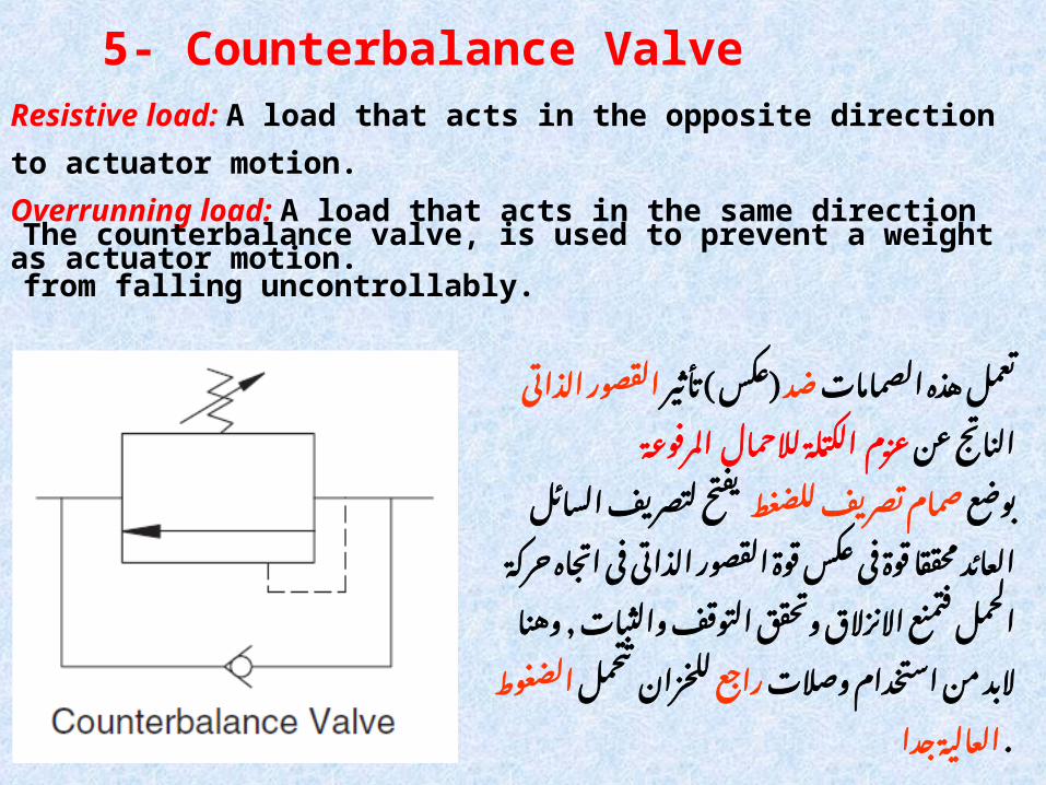
5- Counterbalance ValveResistive load: A load that acts in the opposite direction to actuator motion.Overrunning load: A load that acts in the same direction as actuator motion.
The counterbalance valve, is used to prevent a weight from falling
uncontrollably.
الصمامات هذه تأثير ( ) ضدتعمل عكس
الذاتى عن القصور الكتلة الناتج عزم
المرفوGعة لالحمال
تصريفللضغط بوضع يفتح صمام
فى قوة محققا العائد السائل لتصريف
اتجاه فى الذاتى القصور عكسقوة
وتحقق االنزالق فتمنع الحمل حركة
من , البد وهنا التوقفوالثبات
وصالت تتحمل راجعاستخدام للخزان
جدا العالية . الضغوGط

Circuit Using Counterbalance Valve

1 -If the direction control valve is moved to lower the load, fluid under pressure
flows from the pump into the cap end of the actuator .2- Fluid expelled from the rod end passes into port A of the counterbalance valve.
3- In this position of the directional control valve, the pressure on port B is
reservoir pressure, so the pressure differential across the main fluid control
element is large.
4- The force from the spring operating on the main flow control element is set
some amount higher than the force generated by this pressure differential caused
by the static load.
5- The valve remains closed until more fluid enters the cap side of the actuator
and tries to expel fluid from the rod side. Because the valve is closed, the pressure
at port A rises until the spring load is overcome.
6 -Oil can now pass through the valve to the reservoir.

مع القدرة يوضع وحدة
من. الهيدروليكية لحمايتها
الزائد يتم الحمل حيث
على الصمام اقصى ضبط
للطلمبة به ضغطمسموح
الطوارىء . حالة فى ليفتح
قفلفى كصمام يعمل وقد
التىال الدورة من االجزاء
صمامات بها يوجد
تحكم ذو ويكون الرجوعية
لتوصيل خارجى او داخلى
الى السائل من جزء
الخزان .
6- Safety Valve

Pump protection with a relief valve

Questions1- State Reasons to rise the pressure in the hydraulic circuit?
2- State Different types of pressure control valves?
3- State the function and draw the symbol of Pressure Relief Valve?
4 -State the function and draw the symbol of Safety Valve
![Range of Pressure-Independent Control Valves · The pressure-independent control valve R2...P contains two valves: the self-regu-lating pressure-reducing valve [A] and the control](https://static.documents.pub/doc/80x56/5ed77ad343bb6a56645bfc61/range-of-pressure-independent-control-valves-the-pressure-independent-control-valve.jpg)


