10-l 10. Progress in Fiber-Optic Gyro Development and Applications Wilfried Auch SFIM Industries Deutschland GmbH Gottlieb-Daimler-Str. 60 D-71711 Murr, GERMANY ABSTRACT The SFIM Industries single-axis tïber-optic gyros and inertial measurement units are described. Application areas are identified and rationale is given for the use of the tïber-optic gyro in different market segments. The applications reach from retrofit of mechanical rate gyros to integrated hybrid navigation systems. The ongoing development and engineering effort is now concentrating on miniaturized multiple-axes solutions. The most promising subsystem is a tactical grade inertial measurement unit with a fiber-optic gyro triad as rotation rate sensors. 1. INTRODUCTION Single-axis fïber-optic gyro (FOG) basic design cari be considered as being completed. Areas in which engineering effort is still necessary are improvements of performance limiting elements and analysis of error mechanisms in practical designs and under industrial production conditions. The main driver for ongoing development activities is the need for cost reduction. The known designs have a large number of common characteristics but have also different solutions to FOG specifïc problems with respect to the application area and market segment. Device/System RGP Rate Gyro Package (1 axis) RGA Rate Gyro Assembly (3 axes) IMU Inertial Measurement Unit AHRS AttitudeHeading Reference System GPS/TNS Integrated GPS-aided Inertial Navigation System Configuration 1 FOG 3 FOG or 1 FOG triad 3 FOG or 1 FOG triad 3 Accelerometers IMU processor 3 FOG or 1 FOG triad 3 Accelerometers 1 Magnetometer System processor 3 FOG or 1 FOG triad 3 Accelerometers 1 Magnetometer 1 GPS receiver System processor Gyro Performance 0.1 . .. 0.3 degfs 0.5 . .. 1 % 100 degls 0.1 ... 0.3 degis 0.5 .. 1 % 100 . 800 deg/s 1 ... 10 deg/h 300 . . 500 ppm 400 .. . 800 degls 1 ... 3 deglh 300 .. . 500 ppm 400 .. . 800 degts 0.1 . .. 1 deg/h 100 ... 300 ppm 400 ... 800 degls Application Single-axis stabilisation; Tum indicator; Heading reference for ground vehicle navigation (improved performance required) Multiple-axes stabilisation; Flight control systems Subsystem for guidance and control, and for integrated navigation systems Attitude and heading of a vehicle; Magnetic heading reference Complete position and navigation information; Attitude and heading; Velocity Table 1.1 FOG devices, subsystems, and systems; the FOG performance requirements are given as bias stability, scale factor error, and measurement range Marketing opportunities for the single-axis FOG are a straight forward replacement of single-axis mechanical gyro packages; the use in a very special two-dimensional navigation task, which is as heading gyro in navigation systems for unmanned vehicles; as sensor within a classical inertial sensor assembly consisting of three individual gyros and three accelerometers; and very specific measurement tasks, where package flexibility and environmental conditions are not
Transcript
10-l
10. Progress in Fiber-Optic Gyro Development and Applications
Wilfried Auch
SFIM Industries Deutschland GmbH Gottlieb-Daimler-Str. 60
D-71711 Murr, GERMANY
ABSTRACT
The SFIM Industries single-axis tïber-optic gyros and inertial measurement units are described. Application areas are identified and rationale is given for the use of the tïber-optic gyro in different market segments. The applications reach from retrofit of mechanical rate gyros to integrated hybrid navigation systems. The ongoing development and engineering effort is now concentrating on miniaturized multiple-axes solutions. The most promising subsystem is a tactical grade inertial measurement unit with a fiber-optic gyro triad as rotation rate sensors.
1. INTRODUCTION
Single-axis fïber-optic gyro (FOG) basic design cari be considered as being completed. Areas in which engineering effort is still necessary are improvements of performance limiting elements and analysis of error mechanisms in practical designs and under industrial production conditions. The main driver for ongoing development activities is the need for cost reduction. The known designs have a large number of common characteristics but have also different solutions to FOG specifïc problems with respect to the application area and market segment.
Device/System
RGP Rate Gyro Package (1 axis)
RGA Rate Gyro Assembly (3 axes)
IMU Inertial Measurement Unit
AHRS AttitudeHeading Reference System
GPS/TNS Integrated GPS-aided Inertial Navigation System
Configuration
1 FOG
3 FOG or 1 FOG triad
3 FOG or 1 FOG triad 3 Accelerometers IMU processor
3 FOG or 1 FOG triad 3 Accelerometers 1 Magnetometer System processor
3 FOG or 1 FOG triad 3 Accelerometers 1 Magnetometer 1 GPS receiver System processor
Single-axis stabilisation; Tum indicator; Heading reference for ground vehicle navigation (improved performance required)
Multiple-axes stabilisation; Flight control systems
Subsystem for guidance and control, and for integrated navigation systems
Attitude and heading of a vehicle; Magnetic heading reference
Complete position and navigation information; Attitude and heading; Velocity
Table 1.1 FOG devices, subsystems, and systems; the FOG performance requirements are given as bias stability, scale factor error, and measurement range
Marketing opportunities for the single-axis FOG are a straight forward replacement of single-axis mechanical gyro packages; the use in a very special two-dimensional navigation task, which is as heading gyro in navigation systems for unmanned vehicles; as sensor within a classical inertial sensor assembly consisting of three individual gyros and three accelerometers; and very specific measurement tasks, where package flexibility and environmental conditions are not
10-2
achieved with classical gyros. FOG devices and systems are listed in Table 1 .l in increasing order of complexity and performance, reaching from a simple rate gyro to inertial grade triads. Drivers for new designs of multiple-axis FOGs are the still high power consumption of the FOG, its still considerable size compared to a pure mechanical gyro, and again cost considerations. They are a11 together the reason that FOG multiple axes designs are moving in the direction of triad solutions with multiplexed signal processing and con-mon use of optical components.
2. SINGLE-AXIS FIBER-OPTIC GYROS
2.1 Design and Basic Configuration
The configuration of the Alcatel SEL FOGs has been described in Ref./1,21. The optical part is very similar to the well known minimum configuration of a practical FOG. The readout and signal processing electronics are highly integrated and are implemented as a combined analog and digital ASIC. Block diagrams of the gyro optics and signal processing electronics of the 199 1 rate gyro production units are shown in Fig. 2.1.
For completion the main features of the design are briefly summarized and repeated here as follows:
l As light source a low-cost multimode laserdiode is used with an operational wavelength of 820 mn and up to 1.5 mW of optical power launched into the single-mode fiber pigtail. It is mounted in a half butterfly package with thermo- electric cooler, temperature sensor and monitor diode.
l The multifunctional integrated-optics module contains a pigtailed IOC with polarizer, Y-branch and a pair of phase modulators on a z-tut Lithiumniobate substrate with Ti-indiffused waveguides
l Polarization-preserving tïber is used for the pigtails and the fïber coil, which has a length of 100 m and a Sagnac phase shift of approximately 1 prad for 1 degih input rate.
l The detector module consists of a Si-PIN photodiode with a hybrid preamplitïer circuitry.
l Square-wave phase modulation at the proper frequency of 1 MHz witb a digital demodulation scheme provides the required sensitivity improvement. The demodulation technique with the g-bit converter and without any analog RF mixing and fïltering has already been implemented in 1986 within a tïrst in-house designed ASIC and is described in Ref./l/.
l A new ASIC with analog and digital fïmctions is now used to generate the modulation signal, to demodulate the detector output, and to give improved scale factor performance. Open-loop and a closed-loop operation cari be selected. Scale factor calibration as well as temperature error modelling of bias and scale factor is performed by the single-chip micro controller.
l The gyro has an extended built-in test capability, including power-on BIT, initiated BIT, and periodic BIT for monitoring critical parameters during operation. A minimum number of components is used in the mechanization of the optics and the electronics thus improving the reliability of the device.
The decision to operate the present FOGs in the 820 nm wavelength region is based on the fact that the cheapest light sources with the highest reliability out of a mass production are available in tbis wavelength region. Polarization preserving tïber was chosen for a number of reasons: It gives the cleanest optics concept with the smaller number of splices compared to standard single mode fïber with two depolarizers in the loop. It relieves the requirements for the source incoherence considerably, and it makes at least in tïrst order the gyro insensitive to magnetic tïelds. The cost considerations are tightly coupled to the length of tïber used. The higher cost of the tïber must be compared to the amount of labour cost for e.g. 4 or 6 additional splices if standard single mode tïber were used.
10-3
r-
l / I ! -/DH 1 LP ADC I >
Signal u Processor
I,sR,II”IIpq
<
Vl Modulator
DAC
L--------.--
r--- I I I I I r
I I I Peltier Element
Source Module Temperature Sensor
Detector Module
I Fiber Coil
Fig. 2.1 Block diagram of the FOG-PI-A optics (bottom) and control and signal processing electronics (top)
2.2 Packaging and Production Configurations
Today two single-axis FOG product families are available. Both are based on the same concept, are build with the same optical modules and with the same ASIC, hybrid, and micro controller. They have different packages and have been developed in accordance with different customer requirements.
The FOG-I-B is a gyro with separated sensor and signal processing electronics. Its mechanical design is for applications where the sensors are mounted on a sensor block and the electronics boards are sitting on a motherboard in the PCB compartment of an avionics equipment box. The sensor has a cylindrical shape and is connected to the electronics
10-4
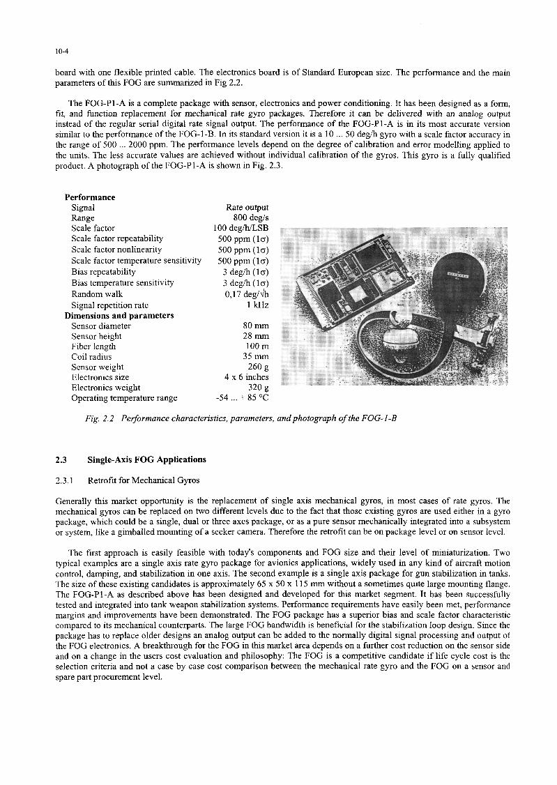
board with one flexible printed table. The electronics board is of Standard European size. The performance and the main parameters of this FOG are summarized in Fig 2.2.
The FOG-Pl-A is a complete package with sensor, electronics and power conditioning. It has been designed as a form, fit, and fimction replacement for mechanical rate gyro packages. Therefore it cari be delivered with an analog output instead of the regular serial digital rate signal output. The performance of the FOG-PI-A is in its most accurate version similar to the performance of the FOG-1-B. In its standard version it is a 10 . . . 50 degih gyro with a scale factor accuracy in the range of 500 2000 ppm. The performance levels depend on the degree of calibration and error modelling applied to the units. The less accurate values are achieved without individual calibration of the gyros. This gyro is a fully qualified product. A photograph of the FOG-Pl-A is shown in Fig. 2.3.
Performance Signal Range Scale factor Scale factor repeatability Scale factor nonlinearity Scale factor temperature sensitivity Bias repeatability Bias temperature sensitivity Random walk Signal repetition rate
Dimensions and parameters Sensor diameter Sensor height Fiber length Coi1 radius Sensor weight Electronics size Electronics weight Operating temperature range
Fig. 2.2 Performance characteristics, parameters, andphotograph of the FOG-I-B
2.3 Single-Axis FOG Applications
2.3.1 Retrofït for Mechanical Gyros
Generally this market opportunity is the replacement of single axis mechanical gyros, in most cases of rate gyros. The mechanical gyros cari be replaced on two different levels due to the fact that those existing gyros are used either in a gyro package, which could be a single, dual or three axes package, or as a pure sensor mechanically integrated into a subsystem or system, like a gimballed mounting of a seeker camera. Therefore the retrofit cari be on package level or on sensor level.
The first approach is easily feasible with today’s components and FOG size and their level of miniaturization. Two typical examples are a single axis rate gyro package for avionics applications, widely used in any kind of aircraft motion control, damping, and stabilization in one axis. The second example is a single axis package for gun stabilization in tanks. The size of these existing candidates is approximately 65 x 50 x 115 mm without a sometimes quite large mounting flange. The FOG-Pl-A as described above has been designed and developed for this market segment. It has been successfully tested and integrated into tank weapon stabilization systems. Performance requirements have easily been met, performance margins and improvements have been demonstrated. The FOG package has a superior bias and scale factor characteristic compared to its mechanical counterparts. The large FOG bandwidth is beneficial for the stabilization loop design. Since the package has to replace older designs an analog output cari be added to the normally digital signal processing and output of the FOG electronics. A breakthrough for the FOG in this market area depends on a further cost reduction on the sensor side and on a change in the users cost evaluation and philosophy: The FOG is a competitive candidate if life cycle cost is the selection criteria and not a case by case cost comparison between the mechanical rate gyro and the FOG on a sensor and spare part procurement level.
10-5
The second possibility is to replace the sensor itself. The typical size of the mechanical gyros inside of these packages is a 50 mm long and 25 mm diameter cylinder, weighing less tban 140 grams. Due to its implementation and specifïc mechanical gyro characteristics tbese gyros need only some drive signal and pick-off signal inputs from the host system and provide an output which cari be directly used by the system without further signal processing. Normally it is an AC output which is demodulated within the systems electronics. TO approach this retrofit opportunity the FOG must be integrated into this cylinder volume and it has to emulate exactly the input and output signals of the old mechanical gyros despite of its completely different sensing mechanism and signal processing. Studies have been done, and the feasibility to place a FOG optics inside of this volume has been demonstrated together with a volume allocation for the electronics. On the electronics side a signifïcant size reduction and integration would be necessary. This cari only be done if a large enough number of identical or at least very similar models of gyros cari be identifïed as replacement candidates.
2.3.2 Ground Vehicle Navigation
A very attractive application for the FOG is in the field of land vehicle or car navigation systems, especially for private cars. The commercial market segment is addressed for example in Ref,/3/. A very special type of land vehicle or car navigation is the navigation and positioning of unmanned ground vehicles in a limited short distance two-dimensional
environment like a factory floor or a container terminal. Vehicles to be guided are fork lifts, tool
---I,.,, v,.. , .- . . ..~ . I carriers, van carriers, trucks etc. -1 :-i ‘Lb .‘ : :;.; ..+,: .: r . *‘-. .; . . . . -._ ,‘$- ,“-$ .g&*?J=..d iT.:“- ,. -*.;*. p’:*-;-p: 9-Q : :a<‘*. . Y - =. .:; : ,,:;. :
sensors, position markers and means for alignment of the vehicle. The need for gyro compassing to get the north reference is circumvented by other solutions. In some cases where the distances are larger and the vehicles are used outside of a building, GPS is the preferred main solution and the gyro in addition to the odometer is installed only for aiding and to guarantee a hundred percent time and position coverage.
In contrast to the rate gyro retrofits the performance requirements for these gyro
Fig. 2.3 Photograph of the single-axis gyro package FOG-Pl -A application are much more demanding. Whereas bias performance requirements are
relieved by position updates, zero-velocity updates etc., the scale factor accuracy of the gyro has to be in the order of 300 to 500 ppm due to 90 deg or 180 deg tums performed by the vehicles before updates take place. On the other hand these systems are new and modem and therefore the digital interface of the FOG, its BIT capabilities and its simple error mechanisms and error models are well acknowledged by the system designers, meaning that today’s FOG cost/performance numbers are very competitive.
2.3.3 Inertial Sensor Assemblies for AHRS, INS, and Derivatives
The classical approach in an AHRS or INS is an inertial sensor assembly (ISA) with individually replaceable sensors. Since the FOG as a stand-alone sensor still has a volume of 8 to 20 cubic inches, in addition requiring a signal processing electronics of a similar volume, its use as replaceable unit in an ISA is today limited to those applications where size and weight are not the main driving factors, and where on the other side FOG specific characteristics are beneficial for the overall systems design. These could be its fast response time, its bandwidth, or unique environmental scenarios like high shock or acceleration loads to the instruments. Another reason is simply the availability of a tactical grade 1 3 degh, 300
500 ppm, 1000 deg/s gyro at a competitive cost level. Systems available and based on SFIM Industries FOGs are a vehicle motion measurement system, an AHRS, and an integrated hybrid navigation system.
10-6
3. MULTIPLE-AXIS FIBER-OPTIC GYROS
3.1 Design Considerations
Complete Inertial Measurement Units (IMU) to determine motion of a vehicle in three-dimensional space have as a minimum without redundancy six sensors, normally three linear accelerometers and three single axis gyros. Driving design parameters in the fïeld of sensor packages for avionics, flight control, and missile guidance are volume, power consumption, and also weight. Especially small size is often more important than an individual performance parameter. Due to the modular structure of the FOG and especially as a result of the flexibility in design, shape, and size of the sensing coil, the size of the optical part of the FOG meets almost a11 requirements known for today’s rate gyro packages and IMUs. An example was given in Section 2.3.1.
In contrast to the small FOG optics is the electronics for a single axis FOG. Depending on performance, ASIC or hybrid implementation, available supply voltages, and interface features, it may have a size up to 100 x 150 mm printed circuit board. Power consumption of a complete FOG with a light source containing a thermo-electric cooler is temperature dependent and is in the range of 5 . 12 W with the highest power consumption at the temperature extremes. Therefore new IMU designs are aimed at a reduction of size and power dissipation of the electronics rather than smaller optical modules. A size reduction cari be obtained without changing the proven readout and signal processing schemes by higher integration of the electronics, e.g. digital and analog ASICs, three charme1 hybrids, external power conditioning, and tailoring for specific applications. A breakthrough however is only possible if multiplexed FOG triads are considered. In order to achieve an optimized multiple-axes FOG design with signiflcantly reduced power consumption and minimum number of parts several steps are possible:
3.2 Single-Source Configuration
The first and most obvious step to optimize a multiple-axes system is to use one common light source to supply a11 FOGs. Light sources available today (especially low-cost multimode laserdiodes with 820 nm wavelength) are powerful enough to supply three FOGs in parallel. Electrical power, volume, and cost of two light sources cari be saved with a tolerable reduction of the optical signal level. If a11 other structures of the axes are left unchanged, there is nearly no impact on the already existing configuration of the underlying single-axis FOG.
3.3 Single-Source and Single-Detector Configuration
The next step for an improvement of multiple-axes systems is to use one common optical detector for the output of the interferometers. The optical (3 x 3)-couplers to distribute the light to the three FOGs and to gather their output on one detector are readily available at reasonable cost. In such a configuration (see Fig. 3.1) it is necessary to implement a method to separate the signals coming from the different axes.
3.3.1 Frequency Multiplexing
By applying different modulation frequencies to the different axes the output signals are also at different frequencies and cari be separated by bandpath filters. An advantage of this method is the in principle continuous operation of a11 axes in parallel. Its disadvantage is the high suppression required to avoid crosstalk between the continuously active modulation and detection circuits. At least three independent modulator circuits are required in the electronics; the length of the fïber coils must be different in order to match the loop transit times to the modulation frequencies.
3.3.2 Time Multiplexing
A straight forward approach is the time multiplexed operation of the different FOG triad axes. The signal processing elec- tronic circuits of a single-axis FOG cari be used for a multiple-axes system if the individual axes cari be switched on and off in a controlled manner. Only simple digital logic is then required to direct the result of the signal processing to an individual output channel. Due to the very fast transfer characteristics of the FOG the switching cari be done at a suffciently high repetition rate without loss of information, e.g. in a vibrating enviromnent. In general two types of switching mechanisms are possible:
l Optical Switching uses active optical switches in the light path to direct light into only one axis of the triad. Complex integrated optics circuits are necessary to achieve high performance switching characteristics.
10-7
l Modulation Switching uses the fact that the Angle-axis FOG described above provides rate output only then when an electrical modulation signal is applied to the phase modulator in the light path of the interferometer. Therefore simple switching of an electrical signal cari be used to activate only one axis at a time. In a consistent design the same electrical functions are used for a11 axes in a time sequence, which on the other hand avoids any crosstalk between the axes as only the functions for one axis are active at the same time. With the exception of the electrical switches, which are readily available, and a small overhead of digital logic to control the switching, the same optical configuration and the same proven signal processing scheme cari be used as in the single-axis FOG. No special optical circuit and no new signal processing scheme have to be developed. For these reasons the modulation-switched time multiplex technique has been chosen by SFIM Industries to be the preferred solution for a compact multiple-axes system.
4 D H LP t ADC 12
, Temperature
RS 232
z
b
Data No Go
Fig. 3.1 Time multiplex FOG triad block diagrams of the optics (bottom) and electronics (top)
10-8
4. FOG BASED INERTIAL MEASUREMENT UNIT
4.1 Design
The tore of the Inertial Measurement Unit FOG-1-3A/B is the time-multiplexed FOG triad. In order to make it an IMU it is completed by three single-axis linear accelerometers, an ASIC for the readout of the accelerometers, and an additional micro-controller to perform IMU related fimctions like temperature modelling and axes misalignment compensation, The Inertial Sensor Assembly (ISA) and two purely digital electronics boards are mounted into a single box. The box has mounting provisions for an optional interface board. The IMU cari be operated with different supply voltages and provides compensated delta-angle and delta-velocity outputs through a fast serial or parallel interface. A top-level block diagram of the IMU func-tions is shown in Fig. 4.1.
l- Accel
Cafibrafion Constanfs
Electronics
Fig. 4.1 Block diagram of a FOG based Inertial Measurement
Flight Control Inertial BIT
Data s
œ
BIT Control
4.2 Hardware description
4.2.1 Optics
The modules used in the FOG triad optics are identical to the modules in the single-axis FOGs. These are a source module, a detector module, a fused 3 x 3 tïber coupler, three IOMs and three tïber coils. The shape of the coils is adapted to the overall mechanical design of the sensor block. Due to the very low failure rate of FOG fïber coils they are potted into the block structure. The design is such that the block cari accommodate either 100 m or 300 m coils, thus giving some flexibility for the costiperformance trade-off. Two electronics modules are attached to a frame holding the block in order to make the electrical interface between the sensor assembly and the processing electronics less critical with respect to shielding, grounding, crosstalk etc. These are the two analog subassemblies containing the functions of the AD conversion and the DA conversion with modulation signal switching. In addition to these FOG modules the block carries three single
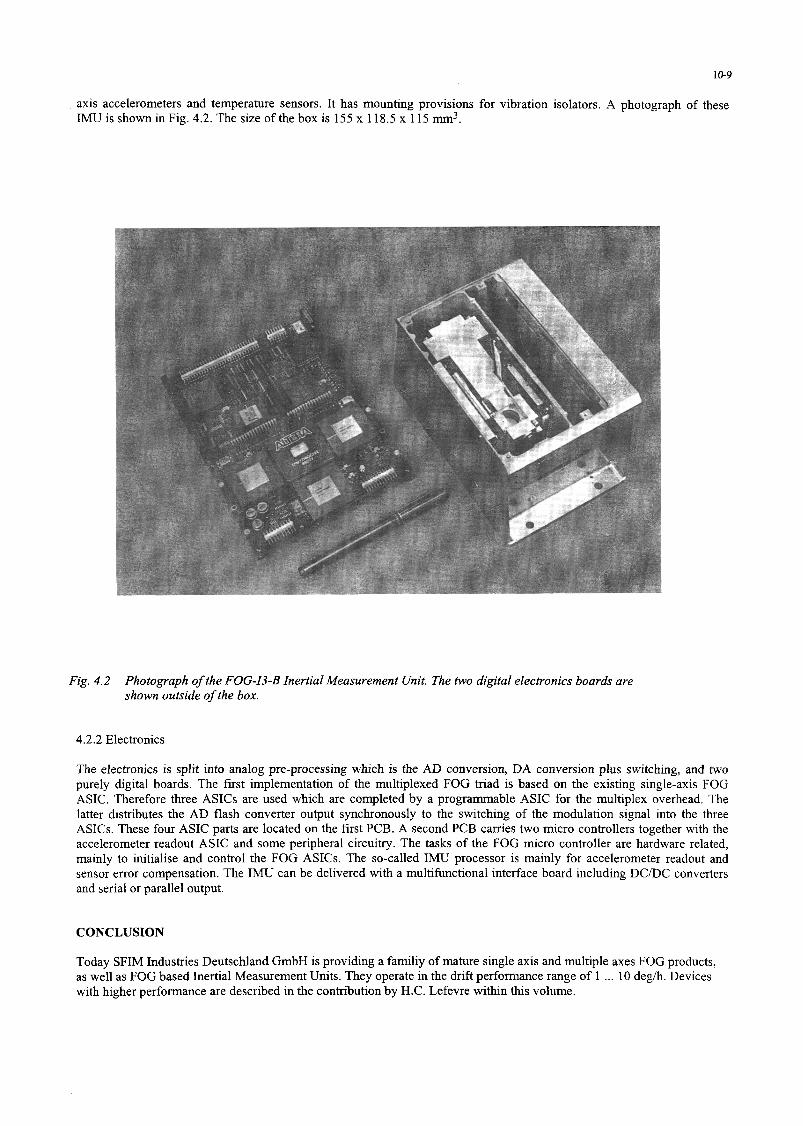
axis accelerometers and temperature sensors. It has mounting provisions for vibration isolators. A photograph of these IMU is shown in Fig. 4.2. The size of the box is 155 x 118.5 x 115 mm3.
Fig. 4.2 Photograph of the FOG-I3-B Inertial Measurement Unit. The two digital electronics boards are shown outside of the box.
4.2.2 Electronics
The electronics is split into analog pre-processing which is the AD conversion, DA conversion plus switching, and two purely digital boards. The fnst implementation of the multiplexed FOG triad is based on the existing single-axis FOG ASIC. Therefore three ASICs are used which are completed by a programmable ASIC for the multiplex overhead. The latter distributes the AD flash converter output synchronously to the switching of the modulation signal into the three ASICs. These four ASIC parts are located on the fïrst PCB. A second PCB carries two micro controllers together with the accelerometer readout ASIC and some peripheral circuitry. The tasks of the FOG micro controller are hardware related, mainly to initialise and control the FOG ASICs. The so-called IMU processor is mainly for accelerometer readout and sensor error compensation. The IMU cari be delivered with a multilùnctional interface board including DC/DC converters and serial or parallel output.
CONCLUSION
Today SFIM Industries Deutschland GmbH is providing a familiy of mature single axis and multiple axes FOG products, as well as FOG based Inertial Measurement Units. They operate in the drift performance range of 1 . . . 10 degh. Devices with higher performance are described in the contribution by H.C. Lefevre within this volume.
10-10
REFERENCES
1. W. Auch, M. Oswald, D. Ruppert “Product development of a tïber optic rate gyro” Proceedings Symposium Gyro Technology, Ed.: H. Sorg, Deutsche Gesellschaft fur Ortung und Navigation, Stuttgart, 1987,
2. W. Auch, M. Oswald, R. Regener “Fiber Optic Gyro Productization at Alcatel SEL” Proceedings Fiber Optic Gyros: 15th Anniversary Conference, Ed.: S. Ezekiel, E. Udd; SPIE Vol. 1585, BostonMA, 199 1,
3. Y. Nishi, T. Iwashita, Y. Nishiura, K. Washimi, K. Okamoto, and A. Oaka “Single Mode Fiber Based Fiber Optic Gyroscope for Automobile Navigation System” Proceedings 9th Optical Fiber Sensors Conference, Firenze, 1993