Solid Edge ® software delivers the best value and lowest total cost of ownership found in the mainstream CAD market today. This paper presents10 reasons why selecting Solid Edge is a wise business decision. white paper 10 reasons to select Solid Edge with SynchronousTechnology 2 www.siemens.com/solidedge Velocity Series PLM Software Answers for industry.
Transcript
Solid Edge® software delivers the best value and lowest total cost of ownershipfound in the mainstream CAD market today. This paper presents 10 reasons whyselecting Solid Edge is a wise business decision.
w h i t e p a p e r
10 reasons to select Solid Edgewith SynchronousTechnology 2
www.siemens.com/solidedge
Velocity Series
PLM SoftwareAnswers for industry.
Table of contentsIntroduction 1
1. Unique paradigm for fast/flexible modeling 2
2. Superior transition from2D to 3D 4
3. Complete productmodeling toolset 6
4. Best sheet metal modelingin its class 8
5. Optimal performance andmanagement of massiveassemblies 9
6. Production-proven2D drafting 10
7. Scalable design andfailure analysis 11
8. Collaboration throughoutthe supply chain 13
9. Scalable design and designmanagement solutions 14
10. Velocity Series 15
10 reasons to select Solid Edge with SynchronousTechnology 2
1
10 reasons to select Solid Edge with SynchronousTechnology 2
Introduction
Most of us know the benefits of a 3D CAD strategy – reducedrework, shortened time-to-market, improved product features andmore. But smart companies succeed because they make smartdecisions.They know not all CAD systems are created equal.
If you want your company to be a market leader, you need to out-innovate your competition.Today’s most forward-thinking companiesare continuously improving their products and processes – andorganizing their value chain so that innovation can flourish. SiemensPLM Software’s Solid Edge is the most cost effective, complete andopen solution for 2D and 3D design and collaboration, helping youmeet these key business requirements:
Solid Edge is what it says – technologically superior 3D CAD, smartservice and support that’s always there, and a product uniquearchitecture that’s designed to take your design into the future.
This document explores 10 solid reasons why more and more smartcompanies are selecting Solid Edge to meet the 5 key businessrequirements listed above. Select Solid Edge – your best option forgaining a competitive edge in product design.
1. Unique paradigm for fast/flexible modeling –Design faster than your competition with yourcurrent design team
The most important question today’s manufacturing companiescontinue to try to answer is “How do we turn escalating customerdemands into highly demanded products?” All face stiff competition on
the road to success,and in a changingmarket place, traditionalsystems and processjust don’t allow you toreact fast enough. Anysavings fromoutsourcing are oftenwashed away whenchanges happen.
To maintain acompetitive edge youneed to out-innovateyour competition and
deliver products faster, to command market share and maximize yourproduct’s potential. Current 3D design technology has been around forsome time. Even with the fastest computers and trained users, currenttechnology is being stretched, stifling your ability to meet even greaterdemands on design throughput.
Solid Edge with Synchronous Technology is the most complete feature-based 2D/3D CAD system available on the market today. It combinesthe speed and flexibility of direct modeling with precise control ofdimension-driven design to provide the fastest, most flexible designexperience possible. Ready to revolutionize the way you think about3D design, Solid Edge with Synchronous Technology allows you to:
• Innovate faster with a new interactive design environment• Iterate designs with unbounded speed and flexibility• Edit outsourced CAD data faster than the vendor who supplied it• Harness the power of 3D with the simplicity of 2D
Capture your ideas as fast as you can think them
Today’s design tools force users to spend precious engineering timepreplanning designs for future use and because current CADtechnology forces edits to follow the create steps, you can’t iteratedifferent design scenarios without starting from scratch. Solid Edgewith Synchronous Technology allows you to create designs as fast asyou can think them and delivers a 100x faster design experience using:
• Integrated 2D and 3D sketching allowing you to draw in 2D, andimmediately creating 3D geometry without separate feature steps
• Region-based design allowing you to identify areas within a sketch ormodel to generate 3D geometry by pulling and pushing into position
• Feature collections features, which are now peers so they are nolonger dependent on each other for your geometry to solve; theycan be used for selection or sorted as you wish
• 3D parametric design allowing you to persist 2D dimensions to 3Dgeometry, use tables and formulas to drive model size and usedirectional control on dimensions
• This powerful concept lets you cut a section view through any partof the model.The resulting 2D cross section can then be editeddirectly, driving 3D geometry
• Sketch driven Procedural Features allow you to edit history-freefeatures through underlying sketches
• Obtain a different patch at blend intersections, and is similar toreordering in a history-based system, again avoiding the cost ofmodel regeneration
• Steering wheel and 3D handles that provide grab-and-go editingcapabilities
• Office 2007 Style user interface and a redesigned EdgeBar thatfurther enhance productivity
If you are using traditional 3D CAD, saving over $76,000 per yearduring your development phase is not an unrealistic figure, even withuncomplicated designs.Traditional CAD forces you to make changesper the creation steps, so any last minute ideas generally require agood bit of rework. Expect to strategize the change, wait for theresults, then fix any problems with downstream failures. By eliminatingthe need to preplan designs, you will realize up to 100 times fasterdesign experience. A faster design experience directly translates intofaster time-to-market so you can capture more revenue quicker.Shorter design cycles will also give you more time to develop newprojects, again further helping your company’s revenue stream.
Change your models as fast as you can change your mind
Today’s traditional CAD tools force change in the same manner ascreate, so users have to spend precious engineering time first, justunderstanding that process. Because those systems use a historyapproach, models have to be constrained a specific way – and usuallynot the way you need – so expect to spend time fixing any brokenfeatures downstream from the change.The most desirable and natural
way to edit is to changethe geometry, not someunderlying constraintsystem, an unrelatedfeature or a parentsketch. Solid Edge withSynchronous Technologyuses a combination ofbreakthrough technologyto allow designmodifications in secondsinstead of hours using:
• Live Rules which automatically find and maintain geometricconditions during a drag or even a dimensional edit, so intuitive aswell as novice users will ‘get it right’
2
10 reasons to select Solid Edge with SynchronousTechnology 2
10 reasons to select Solid Edge with SynchronousTechnology 2
3
• 3D driving dimensions, added directly to your models independentlyfrom creation order to provide directional edit control withexact results
• Procedural features which provide direct access to key parametersfor hole patterns, thinwall and rounds, maintaining feature-baseddesign without feature-to-feature dependencies
• Synchronous solve allowing bidirectional direct geometry editing.Features can be edited regardless of the order they were created,eliminating any parent/child dependencies between features, either ina single part or across multiple components in an assembly
Because edits in a history-based system require both modelregeneration and feature cleanup when things fail, changes becomeunpredictable and time consuming.These problems are compounded asmore and more features are added to your model. With synchronoustechnology Solid Edge suffers no downsides of parametric modelingand delivers performance gains that scale as your model becomesmore complex. Our tests show that performance doesn’t scale withmodel size; with synchronous technology edits are nearly instant. In thechart below notice how the times for synchronous technology are flatacross the board. Using Solid Edge with Synchronous Technology, youcan edit the first operation as fast and easily as the last operation.
Thrive in a multi-CAD world
If you want to design faster than your competition you have to be ableto thrive in a multi-CAD world. So why can’t you do that today? MostCAD systems can interchange data through neutral data exchangeformats.The most common ones are JT, X_T, STEP and IGES.Simplifying the translation, some systems read CAD data directly,skipping the Save As step. However, that’s where the simplicity ends.
In order to manipulate geometry, you need to be able to selectgeometry quickly. Since the import process loses features, you need afast, easy way to select geometry so an automated selection method isa must.
A powerful Selection Manager in Solid Edge provides an automaticselection based on a geometric function.This powerful tool can findgroups of facesthat “look” like arib, boss orcutout. It can alsofind elements thatare parallel,perpendicular andeven cylindricalfaces of equaldiameter. TheSelection Managerworks the samefor native or imported data so users aren’t burdened with learningcommands specific to handling just-imported data.The geometry foundcan be saved into a user-defined feature for future edits or added to afeature library for re-use later.
Figures from our studies show how companies using Solid Edge withSynchronous Technology can save over $38,000 per year by avoidingdowntime and waiting on updates from their suppliers.
Solid Edge with SynchronousTechnology business advantage #1:
• Design faster than your competition with your current design team
• Capture your ideas as fast as you can think them• Eliminate model regeneration and perform ECOs in seconds• No need to preplan your designs• Get up to a 100x faster design experience• Faster time-to-market – means more revenue• More products – with no more costs• More iteration means higher quality designs
• Change your models as fast as you can change your mind• Make design changes at will, without having to preplan your design• Eliminate model regeneration during design time• Improve customer response time for more repeat business• Increase design re-use and reduce costs for redevelopment• Fewer modification steps lessens chance for errors
• Thrive in a multi-CAD world• Edit imported data as native Solid Edge• Make changes up to 100x faster than the supplier – even
SolidWorks or Autodesk Inventor• Less downtime waiting for supplier turnarounds• In-house changes eliminates supplier change fees• Eliminate quality issues with 2D markups using edited 3D models
For more details on Solid Edge with Synchronous Technology, ask yoursalesperson for a copy of the Solid Edge with Synchronous Technologyfact sheet, or download directly from www.solidedge.com.
Traditional Technology Synchronous Technology
Tota
ledi
ttim
e(m
in)
200 573 1664 25630
10
20
30
40
50
60
70
Model edit performance
Face count
4
2. Superior transition from 2D to 3D
Many companies transitioning from AutoCAD and other 2D productsfind that learning and maintaining multiple design systems hinders theirsmooth transition to the productive world of 3D. The traditionalanswer from 3D vendors is to give up on your 2D data and jump headfirst into 3D. Solid Edge is the only practical design system allowing youto create from scratch 2D data, and edit or maintain your legacy 2Ddata from multiple systems while you move to 3D – at your own paceand using a single product. By following Siemens’ proven 4-step “evolveto 3D” process, users upgrading from 2D AutoCAD to Solid Edgeenjoy a smooth workflow and a consistent, familiar look and feel totheir drawings – shortening the learning curve while ensuringconsistency and data integrity.
Step 1 Continue today’s 2D productivity while learningtomorrow’s 3D design tools
Step 2 Turn 2D geometry into real 3D parts
Step 3 Apply the power of a hybrid 2D/3D design workflow
Step 4 Realize the benefits of PLM with Solid Edge andVelocity Series™ software
Migrate 2D dimensions into 3D
If you're migrating from a 2D system into Solid Edge, all 2D dimensionsare retained during the transition to 3D and automatically becomeeditable 3D Driving Dimensions.Whether you are migrating fromAutoCAD, ME10 or even DXF, 2D dimensions such as linear and radial,placed when you created your drawing are used to drive 3D geometrywithout additional work.Those dimensions can be locked to preserve
values, linked to other dimensions through equations, and evencontrolled through a spreadsheet. Solid Edge preserves yourinvestment in 2D drawings while realizing immediate value with themove to 3D.
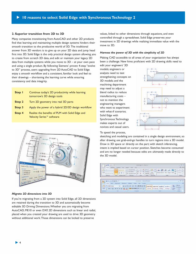
Harness the power of 3D with the simplicity of 2D
Making CAD accessible to all areas of your organization has alwaysbeen a challenge. New hires proficient with 2D drawing skills need toedit your engineers’ 3Dmodels; engineers oranalysts need to teststrengthening concepts on3D models; and themachining departmentmay need to adjust ablend radius to reducemanufacturing costs –not to mention theengineering managerswho want to experimentwith what-if scenarios.Solid Edge withSynchronous Technologymakes experts out ofnovices and casual users.
To speed the process,sketching and modeling are contained in a single design environment, soafter drawing use grab-and-go handles to turn regions into a 3D model.Draw in 3D space or directly on the part; with sketch inferencing,intent is implied based on cursor position. Sketches become consumedand are no longer needed because edits are ultimately made directly tothe 3D model.
10 reasons to select Solid Edge with Synchronous Technology 2
10 reasons to select Solid Edge with SynchronousTechnology 2
5
Free 2D
Solid Edge is the most complete 2D and 3D design systemin its class.Whether you want to perform 2D company-wide or specific 2D design processes, you will benefit fromSolid Edge 2D Drafting. Solid Edge 2D Drafting capitalizeson 10 years of production-proven capabilities developed forSolid Edge, and offers excellent drawing layout, diagramming,Goal Seeking, annotation and dimensioning controls thatautomatically comply with a wide range of draftingstandards – including ISO,ANSI, BSI, DIN, JIS and UNI. Andit is absolutely FREE to download and use.
True WYSIWYG (what you see is what you get) of imported AutoCADDXF/DWG files, including matching color schemes, fonts, styles andbackgrounds, means AutoCAD files look the same in Solid Edge as theydid in AutoCAD. The AutoCAD Import wizard provides enhancedpreview capabilities (pan, zoom, window area) to help users fine tuneand predict translation results. Solid Edge 2D is so complete there isno reason for companies serious about transitioning to 3D to rely onAutodesk products. All 2D translation capabilities are available with fullSolid Edge or Free 2D drafting.
Supporting this practical workflow, highly efficient hybrid 2D/3D designcapabilities make Solid Edge unique in its ability to capitalize on a mixof existing and new data – in both 2D and 3D formats – to keepprojects moving at a swift pace and allow key design decisions to bemade earlier in the process. With Solid Edge, you choose the right toolfor the right job at the right time, while continuing to keep allgeometry in sync. Add the unique capabilities of Zero D, with its abilityto establish product structure before committing to any geometry, andSolid Edge leads the industry with a simple 4-step workflow fromstructure to 2D layout to 3D model.
For more information, ask to see Siemens PLM Software’s white paperon Hybrid 2D/3D.
Solid Edge business advantage #2
Practical evolution from 2D:• Solid Edge’s 4-step evolve to 3D process lets you move from 2D to
3D at a pace that makes sense for your business, without losing theinvestment you have made in 2D data
• By leveraging existing 2D data to create 3D components for newdesign projects, you continue to gain from your original investmentwhile learning the same tools that will increase your 3D productivity
• AutoCAD import wizards enable 2D data to look the same in SolidEdge as it did in AutoCAD, so your users are instantly familiar withthe drawings and don’t need to go through a steep learning curve
• Easy access to DWG and other 2D files means you can work withclients using Autodesk products without having to maintain separateCAD systems
• Hybrid 2D/3D design capabilities let you use the right mix of 2Dlayout and 3D design tools, to keep projects moving and shortendesign cycles
• Using Solid Edge to intelligently combine existing or new, 2D and 3Ddata, lets you create the right level of detail to generate accuratebids in less time
• Solid Edge Zero D introducestangible productivity gains andcost savings through bettercoordination of design teamactivities; project leaders canplan ahead of time, lettingdesign engineers to focus ontheir area of specialization
• Using Solid Edge as a singlesource for all your 2D and 3Ddesign requirements reduces your IT costs and lowers your totalcost of ownership for CAD technologies
• You can control costs by deploying free Solid Edge 2D Draftingcompany-wide or complement Solid Edge with 2D specific designprocesses
6
3. Complete product modeling toolset
Solid Edge boosts design productivity with specialized commands andenviron-ments to help you design much more quickly than withgeneral-purpose CAD modeling tools. Fully tailored environments usestandard terminologies and streamlined modeling commands toaccelerate the design of plastic parts, frames, weldments, sheet metal,tubing, piping and wiring, plus rendered images. Process-specific featuresprovide step-by-step guided workflows for creating individual featuresthat are common to specific industries.
A case in point is Solid Edge’sexceptional sheet metal designcapabil-ities, now withsynchronous technology.Process specific features andworkflows provide users with acompetitive advantage bysignificantly enhancingproductivity from sheet metalcomponent design throughdocumentation andmanufacture.
Solid Edge streamlines drawing creation with the industry’s mostproductive drafting system. Formed and flattened components canbe detailed and dimensioned and remain associative so theyautomatically update when you change your design. Innovative tools forshaded views, exploded assemblies, detail and section views, hole tablesand coordinate dimensioning all ensure that you represent your partsin the best possible way for customers and manufacturing.
Model validation is another area where Solid Edge is unmatched. SolidEdge Sheet Metal ensures parts can be manufactured. Manufacturingsupport is an area where Solid Edge Sheet Metal excels. Its save flat asDXF and flat pattern generation commands allow the user to create aCAM-ready flat pattern DXF file directly from the sheet metal modelwithout the need to create a drawing first.
For more information, ask to see Siemens PLM Software’s Sheet Metalwhite paper.
Other process-specific workflows are provided for:• Frame design, for the development of rigid frame structures• Weldments, for accelerating the design and documentation of
weldments• Piping and tubing, for a comprehensive set of design tools help
designers quickly route and model piping and tubing in Solid Edgeassemblies
• Engineering Reference, for integrating calculation-drivendesign tools that remove the guesswork from part design andeliminate the need for detailed analysis, providing a ‘right the firsttime’ design method
• Wire harness design, for integrating popular electrical wiring designpackages and Solid Edge, as well as for a full suite of tools for wireand harness creation
• Standard parts, for providing a powerful parts management systemthat allows designers to define, store, select and position commonlyused parts
10 reasons to select Solid Edge with SynchronousTechnology 2
10 reasons to select Solid Edge with SynchronousTechnology 2
7
• Fastener Systems, for grouping relevant hardware such as nuts, boltsand washers with mechanical fasteners like bolts, screws, rivets etc.and creating correct clearance or threaded holes in adjacentcomponents being fastened on placement
• Photorealistic and artistic rendering, for a full range of renderingoptions for concept reviews right through to promotional materials
• Mold design, for establishing a powerful automated workflow thatmakes it fast and easy to design plastic injection molds
Common throughout each of these environments is the uniquelyergonomic Stream XP user interface, making Solid Edge easy to learnand use, and delivering a rapid return on your investment.
Solid Edge business advantage #3
Process-specific applications:• Design better products by focusing on the engineering aspects of
your projects while Solid Edge takes care of your process specificdetails such as wire properties or sheet metal bend radius
• Enjoy a faster return on your technology investment throughStream XP – a highly productive user interface that enables bothcasual and full-time users to achieve more in less time
• Reduce ECOs and costly rework by using process specificapplications to manage critical design details for specific processes
• Reduce training costs through step-by-step instructions and wizardsthat guide you through streamlined design processes
• Build better products and reduce design time by capturing andmonitoring key design parameters, such as maximum wire bundlesize or manufacturability of sheet metal components
• Remove duplication waste and errors through automatedmanufacturing information, such as sheet metal flat patterns andreporting of tube or wire cut lengths
• Optimize resources by standardizing and reusing commoncomponents, such as fasteners and pipe fittings
4. Best sheet metal modeling in its class
A core design capability of Solid Edge software, the Sheet Metalenvironment provides an entire design-through-fabrication workflow,using streamlined modeling commands that are tailored to the uniqueneeds of sheet metal design. Dedicated process-specific sheet metaldesign tools provide for efficient design of electrical cabinets, guards,HVAC and more.
If you design sheet metal parts, you face some unique challenges.Although parts are typically designed in their “formed” state, they beginas a flat sheet so manufacturability becomes a critical aspect of everyfeature making up the finished part. Add to this the need to accountfor material thickness, along with bend and corner relief, miters anddeformation features and it becomes obvious that you need a highlyspecialized set of tools if real productivity and quality gains are tobe realized.
Unmatched sheet metal design productivity
Solid Edge’s specialized sheet metal design aids deliver significantproductivity gains compared to general-purpose CAD tools. Process-specific commands and structured workflows speed the modeling ofsheet metal parts. Built-in intelligence saves additional time byautomatically calculating material treatments and validating parts formanufacturability, while manufacturing-ready flat patterns help toeliminate scrap and rework.The result is faster time to manufacturing,backed by improved quality of the sheet metal components.
SynchronousTechnology
Solid Edge with Synchronous Technology in sheet metal unlocks designfreedom, make changes fast and easy, uses foreign data as though itwere native and is so easy you don't need to be a cad expert to getresults. Most traditional history-based 3D CAD systems require specialcommands and work flows to create even simple parts. This requires
specialized training andrisks downtime duringadoption, Solid Edgeremoves these barriers.While designing sheetmetal parts in traditional3D CAD is faster than 2D,history-based systems forceyou to pre-plan designs toaccommodate futurechanges. Unless models arecarefully constructed, someedits can’t be made without
starting from scratch, not so with synchronous technology. Engineersmigrating from 2D may not be aware of the process change whenmoving to a traditional 3D CAD system, in-house edits to imported3D data can’t be made in traditional systems, which can result inadditional supplier change fees.There are some productive modelingmethods in 2D that simply can’t be duplicated in traditional 3D. Withsynchronous technology you can, for example "3D fence stretch" isreminiscent of 2D editing techniques, removing the need for new usersto learn steps that are less efficient.
Built-in support for the sheet metal process
Solid Edge’s specialized process-specific commands streamline thedesign of sheet metal components by using familiar terminology and aprocess that requires significantly fewer steps.
You enter part properties – material, thickness, bend relief and bendequations etc. – in one place and your sheet metal parts automaticallyadhere to these predefined material specifications without having todefine new properties each time you add a new feature.
Intelligent sheet metal features
Solid Edge Sheet Metal understands the unique challenges of workingwith sheet metal parts.When cutouts or holes lie across a bend, atraditional cutout command would result in non-perpendicular faces.
By contrast, Solid Edge’s normal cutout command creates accurateperpendicular faces, reflecting the fact that the feature would likely bemanufactured while flat, then folded.
Ensuring manufacturability
Model validation is another area where Solid Edge sheet metal isunmatched. A classic manufacturing issue involves cutouts or flangesplaced too close in proximity to other cutouts or bends. Typically thereis a minimum distance between bends that must be maintained toaccommodate the bend die. Designers are aware of this but often don’tmeasure each bend for validation. Solid Edge includes design sensorsthat handle this operation automatically
8
10 reasons to select Solid Edge with SynchronousTechnology 2
Manufacturing support
Manufacturing support is an area where Solid Edge Sheet Metal excels.Its save flat as DXF and flat pattern generation commands allow theuser to create a CAM-ready flat pattern DXF file directly from thesheet metal model without the need to create a drawing first.
There is a thin line between sheet metal design and manufacturingresponsibilities, more so than most design disciplines.Where thedesigner leaves off and the production engineer takes over is oftendictated by the size of the company. Many times it is the designengineer who has to decide how components need to be made.Siemens recognizes this scenario and provides manufacturing supportthat can be completed at the design or manufacturing stages.
Highly productive drafting
Solid Edge streamlines drawing creation with the industry’s mostproductive drafting system. Formed and flattened components can bedetailed and dimensioned and remain associative so they automaticallyupdate when you change your design. Innovative tools for shadedviews, exploded assemblies, detail and section views, hole tables andcoordinate dimensioning all ensure that you represent your parts inthe best possible way for customers and manufacturing.
5. Optimal performance and managementof massive assemblies
Solid Edge customers are creating assemblies well in excess of 100,000parts. Optimal performance is essential to be able to work interactivelywith assemblies of this magnitude. Solid Edge has a long tradition ofleadership in this area with many unique capabilities to make itpractical to work with large data sets. Other companies market theability to open and display large assemblies, but that is a very small partof the designer’s workflow. Of greater importance is the ability tonavigate, manipulate and document assemblies efficiently and effectively.
Solid Edge was the first to introduce the concept of simplifiedassemblies. Storing and opening assemblies with any combination of“simplified” or “detailed” parts ensures maximum performance, withoutlimiting user interaction. Innovative selection and display options allowyou to navigate the entire assembly tree structure without theoverhead of the entire assembly, eliminating clutter and quickly isolatingcomponents necessary for each design task. And when drawings needto be generated, the combination of simplified assemblies and draftquality views ensure that you can quickly place detail views.
For some time now, advanced assembly design capabilities in Solid Edgehave been used by many companies such as VAI, Anglo Platinum andKrones to lay out their factory floors and design equipment for theirplants. Solid Edge, a leader in massive assembly design, now takes thenext step to making it even easier to lay out and document factoryfloors. With new capabilities to open and work with actual machinegeometry in the context of large assemblies and their associateddrawings, Solid Edge further addresses the needs of the heavy industrialvehicles, large mechanical machinery, process plant equipment andpower industries.
Solid Edge is the first mid-range modeler to takeadvantage of zones. Zonesmake working with massiveassemblies even moremanageable and boostperformance, allowingdesigners to define apermanent range box toisolate areas of largedesigns they are responsible for at a subsystem level. Intelligent cachingallows retrieval of only the parts in the zone, without having to opencomponent files to determine if they lie in the zone or not. Thiscreates a significant performance boost when switching zones oropening a massive assembly.
To help designers lay out factory floors and/or machine designs, manualcomponent positioning capability allows existing subassemblies to bequickly copied, moved, rotated or arrayed within an assembly. To
10 reasons to select Solid Edge with SynchronousTechnology 2
9
10
remove any restrictions, assembly relationships to existing componentsare ignored, while those integral to the subassembly remain intact.Subassemblies can be simply dragged to a new location or preciselymoved using coordinates, vectors or exiting components.
Systems Design is a unique Solid Edge approach to building intelligentassemblies. Where traditional assembly design focuses primarily onhow parts fit together, Systems Design places additional emphasis onfunction, allowing you to create intelligent digital prototypes thatemulate the real-world situations for which they are being designed.Motion simulation tools in Solid Edge let you create fast, accurate andrealistic conceptual motion studies during the design phase, quickly andeasily defining motion relationships and drivers, such as: gears, pulleys,hydraulic cylinders and motors.
If you regularly work with massiveassemblies and/or their associateddrawings, the 64-bit edition of SolidEdge gives you the extra horsepoweryou may need.
For more information, ask to seeSiemens PLM Software’s white paper on Large Assembly Performance.
Solid Edge business advantage #5
Optimal performance and management of massive assemblies:• Solid Edge’s capability to create a complete digital mockup of your
designs means you find problems early in the cycle, helping you avoidECOs and costly rework
• Focused tools for assembly manipulation and visualization let youfocus on the design task at hand, rather than battling softwareperformance
• You can extend Solid Edge large assembly design capabilities intoplant equipment design and layout on factory floors
• Systems Design capabilities allow part and assembly intelligence tobe captured and stored as a single unit, saving time and money byoptimizing and reusing parts, processes and materials
• Powerful production ready drawing tools mean you can rapidlycreate 2D drawings of even the largest assemblies in record time
• Sensors monitor critical design variables, keeping projects on timeand on budget by checking for manufacturability, build errors, costincreases and more
• Dynamic “on-the-fly” creation and configuration of assembly familiessaves significant design time by quickly configuring new or customdesign and product lines
• System libraries promote commonality and optimize resources byeasily finding and reusing common components, sub-assemblies andmounting details
6. Production-proven 2D drafting
Solid Edge leads the market in drawing creation productivity with afocus on the four key components that affect the time required toprogress from design to print, namely layout, performance, annotationand revision. With Solid Edge, you simply select the 3D model, andstandard views are automatically created. Additional views such assections or details are added with a simple click. Exploded views,balloons, parts lists and BOMs are easily created and updated aschanges are made to your 3D models. Quicksheet templates eliminaterepetitive tasks by predefining a drawing template that automaticallydefines the layout for new drawings, including all standard sections anddetail views, as well as parts lists and balloons. Innovative managementtools make it practical to develop detail drawings from your largestassemblies, while practical and intelligent dimensioning and annotationtools means you can create fully dimensioned views in seconds.
As your designs evolve and change, so too must any associateddocumentation. Unique Solid Edge tools persistently monitor your 3Dmodel and automatically highlight and tag views and dimensions thatare no longer current relative to the model. By understanding whyyour drawings are out of date, and having Solid Edge tell you whatneeds to be done to update the drawing, you can make faster andmore accurate revisions, without the need for detailed and lengthymanual checks.
Solid Edge’s complete 2D drawing tools are augmented with a new‘drawing review mode’ that allows rapid opening of a drawing forreviewing, adding dimensions, measuring or printing regardless of howbig or detailed your drawing. Solid Edge Draft’s unique architectureallows instant opening drawings of massive assemblies that drasticallydecrease drawing access time from minutes to seconds. Inactive
10 reasons to select Solid Edge with SynchronousTechnology 2
drawings, as they are referred to, allow you to add dimensions andannotations, and extract part numbers. Inactive Drawings are ideal fordrawing reviews, quick print jobs for the shop floor, continued detailingby teams with or without 3D data being present.
Solid Edge Goal Seeking takes graphical engineering problem solving toa new level and avoids labor intensive iterative calculations by allowingdesign engineers to perform two-dimensional what-if engineeringcalculations, with a combination of 2D parametric geometry,mathematical formulas, variables and part properties. Knowing thetarget value of an engineering calculation, Goal Seeking allows users toset certain parameters, while the system varies other factors to achievethe desired result. Goal Seeking concepts, familiar to many, in Excelspreadsheets have now been applied to engineering and design byallowing engineers to solve problems that are best expressedgraphically. Results can be used to drive 3D geometry in a true hybrid2D/3D design environment.
Solid Edge business advantage #6
Production-proven 2D drafting:• Start in 2D or finish in 2D; Solid Edge’s drafting environment enables
you to be more agile, giving you flexibility to edit and maintainexisting 2D drawings, create new 2D layouts or develop drawingsfrom 3D models
• Provide accurate manufacturing information using Solid Edge’s fullsuite of dimensioning and annotation capabilities that adhere tointernational standards
• Deliver more accurate bids in less time through the ability toquickly create fully detailed drawings from multiple configurations ofyour products
• Take advantage of Solid Edge’s free 2D/3D view and markup tools toopen up design data to your extended organization; collaborate withyour customers and suppliers, and find errors early while costs are low
• Avoid costly rework through Solid Edge’s ability to track andmaintain associativity between the 3D model and its many differentdrawings; drawing views give immediate feedback that designs havechanged, while revision and version controls mean that data is alwaysaccurate and up-to-date
• Speed time-to-bid and time-to-market through automated bill ofmaterials and parts lists that are accessible by purchasing and otherdepartments
• Customize Solid Edge’s standard drawing and quicksheet templatesto meet your company or customer standards and ensure alldocumentation automatically adheres to design standards, processes,materials and templates
7. Scalable design and failure analysis
The job that today’s engineers are faced with has to cover a multitudeof tasks in all phases of product development including analysis, andinvolves the use of several products, each with it’s own user interfaceand method of working. Often tasks like simulation are outsourced,which has the effect of separating analysis from the design process.Thisreduces the number of analyses that can be performed, and preventsanalysis from being used for investigative studies which overall inhibitsinnovation in design. Some of the solutions available today are overlysimplistic in their approach to simulation which can compromisesolution accuracy and create misleading results.The inability to editgeometry easily after analysis and the lack of CAD associativity withsimulation inhibit the fast turnaround necessary for timely and effectivedesign refinement.
Siemens PLM Software owns and develops Femap® software – theworld’s leading advanced engineering analysis environment. Writtenby engineers for engineers, Femap is widely used by the world’s leadingengineering organizations, with more than 20,000 direct customers,of all sizes, in all industries. Femap’s powerful in-depth functionalitysolves challenging engineering problems quickly and easily.
11
10 reasons to select Solid Edge with SynchronousTechnology 2
12
Solid Edge is able to take advantage of Siemens’ unique position withFemap to offer three complementary methods for design analysis andvalidation.These solutions also utilize well-proven Nastran solvertechnology for accurate and repeatable results.
Created specifically for design engineers, Simulation Express providespreconfigured, best practice, process guidance to the user for fast,accurate finite element analysis (FEA). Using the same process basedapproach found in other Solid Edge capabilities, finite elementtechnology is presented to the user in an easy-to-follow workflowand detailed analysis tasks are undertaken within a single SolidEdge window for static and modal analysis of single parts.
Solid Edge Simulation sits between Simulation Express and Femap.Aimed at design engineers, Solid Edge Simulation allows you to digitallyvalidate your designs inside the Solid Edge environment.The familiarSolid Edge user interface is process oriented and guides you throughthe entire analysis procedure helping you set up the finite element
model in astraightforwardmanner. Finiteelementmodeling entitiesare based on thegeometry model,and the interfacedialogs arewritten inthe moreunderstandablelanguage ofdesign. By
bringing simulation into Solid Edge, engineers can accomplish a greatervariety of tasks such as party or assembly studies for statics, modal orbuckling with complete mesh control within a single product.
The job doesn’t finish at the end of the analysis. Solid Edgesynchronous technology with CAD model associativity is used tospeed up any necessary model refinement and update after theanalysis.The feature-based and history-free geometric modelingfeatures allow easier model updating, and associativity between theCAD and simulation model is maintained. Procedural features forparametric edits ensure fast and trouble-free model updating, and don’tneed to follow the original order in which features were modeled. Anyapplied loads and constraints applied to the model are maintainedautomatically during model changes. Mesh refinements also update tokeep in line with modified geometry.With Solid Edge, effective designrefinement can be completed in less time which results in higherquality products and reduced time to market.
Based on the industry standard NX Nastran solver, you can be sure offast accurate results and scalability to Femap for analysts.
For more detailed and advanced analysis, Solid Edge models can beassociatively passed to Femap. Femap from Siemens is the world’sleading window’s-based engineering simulation tool for FEA. Engineersworldwide use Femap to model and simulate everything from simplesolid components to entire spacecraft assemblies throughout a broadrange of engineering disciplines. From simple linear static analysis rightthrough to advanced solutions-based computational fluid dynamics,engineers and analysts use Femap to virtually simulate a completerange of product behavior before committing to expensive productdevelopment plans.
Solid Edge business advantage #7
Scalable design and failure analysis:• Reduce the need for physical prototypes which brings significant
time and cost savings• Savings can also be made by using simulation to increase product
quality which reduces product failure andcostly recalls
• Design optimization ensures that designs are as efficient as they canbe by minimizing material and weight, but overall simulationpromotes design innovation to produce objective results
• Perform fastaccurate analysis,and validatethat parts are‘fit-for-purpose’without buildingphysical prototypes
• By moving analysis toan earlier stage in thedesign cycle, you ensuredesigns will function as intendedand avoid ECOs, costly rework and recalls
10 reasons to select Solid Edge with SynchronousTechnology 2
13
• You can avoid process duplication and waste by eliminating theneed to build separate, meshed geometric models in order to runFEA analyses
• You can lower development costs by aligning CAD design and FEAtechnology and working together within a common user interfacethat enables design engineers to quickly assess whether designs willmeet specifications
• You can enjoy peace of mind by knowing that you are using proventechnologies that are scalable to meet your growing businessrequirements; Femap is widely recognized as the world’s leadingWindows-based engineering simulation tool for finite elementanalysis. The Nastran-based solver is well recognized and respectedthroughout the industry
8. Collaboration throughout the supply chain
Global companies require efficient tools for exchanging design data,even when their partners are using disparate design tools. With over4 million users worldwide, JT is proven technology and widelyaccepted as the standard for collaboration, allowing anyone in yoursupply chain to share intelligent 3D data regardless of the CAD systemused to create the file. JT files contain all the important design dataneeded to collaborate in today’s engineering world. Differentcombinations of geometry information, assembly structure andattributes allow OEMs and suppliers to share a level of “intelligence”with a level of security that is appropriate to each shared project.
With enhanced 3D annotation tools in Solid Edge, productmanufacturing information (PMI) is easily stored with 3D models andassemblies. These “smart” models reduce the need for drawings indesign reviews and can be used for many downstream purposes,including manufacturing.The inclusion of 3D product definition in asingle digital file improves productivity, ensures the 3D information isaccurate and in sync and removes the need to keep multipledocuments up to date.
Fully supporting both JT and PMI data, XpresReview is an electronicdesign review solution that allows you to easily share multipledocuments in a collaborative environment. Used independently or inconjunction with Solid Edge or NX™ software, XpresReview easilycombines 3D models and other associated documents into a singlepackage collaboration file (PCF), so participants in your review processhave all the information they need to communicate effectively.Recipients of the package can use XpresReview to quickly and easilyinterrogate its contents – viewing, measuring and marking up the data.
Solid Edge business advantage #8
Collaboration throughout the supply chain:• Communicating with customers and suppliers using easy-to-visualize,
accurate and up-to-date information reduces misinterpretation asdesigns pass through supply chain
• Solid Edge’s collaboration tools allow shortened and more decisivedesign reviews and help cross department and cross functionalteams make faster decisions to meet shrinking delivery cycles andcustomer expectations
• Different combinations of geometry information, assembly structureand attributes allow OEMs and suppliers to share a level of“intelligence” with a level of security that is appropriate to theirshared projects
• By quickly evaluatingdesign options early inthe design phase, changescan be incorporated orerrors spotted whilecosts are low
• PMI data within 3Dmodel delivers a digitalrepresentation of aproduct, so criticalinformation is alwaysaccurate and up to date,reducing ECOs andcostly rework
• Design teams and theiractivities are bettercoordinated reducingwasteful stages in thereview process
10 reasons to select Solid Edge with SynchronousTechnology 2
14
• PMI rich “smart” models reduce the need for drawings in designreviews and can be used for many downstream purposes, supportinglean initiatives and manufacturing
• PMI information in Solid Edge is in compliance with world standards,supporting initiatives with global partners
• PMI can be viewed by shop floor assembly workers or maintenanceengineers to reduce assembly time and serve as training aids, aswell as delivering better maintenance and support documentationwith products
• 3D Dimensions created in PMI views, can save time creating 2Ddrawings – they can be extracted as and when 2D drawingsare required
9. Scalable design and design management solutions
Unique in the PLM industry – scalability and interoperability with allproducts in our portfolio is a core vision of Siemens PLM Software.Siemens has a clear and consistent development strategy, allowingdifferent products to co-exist, offering a safe, scalable approach forboth design and data management. If you are already using productsfrom our portfolio, Siemens is committed to providing functionalitythat allows Solid Edge to coexist within your organization. Solid Edge iscompletely scalable and extensible to both NX and the Teamcenter®
software portfolios when your business requirements change. Siemens’associative embedding technology is already production proven withmany customers using combinations of NX and Solid Edge. Eachproduct contains exclusive technology to allow part, assembly
and attributeinformation tobe passedbetween them.Solid Edge partscan be used inNX assemblies,with designershaving the abilityto update any ofthe parts fromthe assembly
level in NX. Associative embedding ensures that updates to the originalfiles will be recognized and acted upon in either system, keepingcollaborative projects in sync at all times.With Solid Edge and NX,Siemens offers the industry’s only full CAD spectrum, ensuring thesuccess of your technology investment.
With its groundbreaking Insight technology, Solid Edge became theonly mainstream mechanical system to merge design managementcapabilities with the CAD tools that designers use every day. Buildingon the success of Insight, Siemens now lets you choose from a rangeof easily scalable cPDM solutions, setting a new standard in CAD/PDMintegration with Solid Edge. Solid Edge Insight continues to provide
provenmanagementcapabilities fordepartmentalteams, now basedon sharePoint 3.0,resulting inimproved visibilityof the designprocess andimprovedcollaboration
between departments. Solid Edge’s integration with the powerfulTeamcenter platform provides seamless and transparent connectivitybetween the applications. All essential Solid Edge commands areencapsulated, making sophisticated data management functions easilyavailable. Solid Edge-related data is easily captured for re-use in futureprojects without placing an additional burden on the designer, while fullscalability means you can grow your cPDM solution to meet growingbusiness demands without starting from scratch.
Solid Edge business advantage #9
Solid Edge is the first CAD application to support Teamcenter serviceoriented architecture (SOA) providing robustness, performance andsupport for the new Teamcenter architecture that allows access to acentral database from remote sites via company wide area networks.
Scalable design and design management solutions:• With SharePoint already in use with many organizations, less time is
needed for implementation of the software. Integration to Solid Edgeand Microsoft Office is in place as part of the standardimplementation and client software costs can be as little as zero asiIsight is included with Solid Edge. User training is also faster as thereis no new interface to learn
• Insight also has a significant impact on designer’s productivity. Theywill spend less time on non-productive tasks such as searching fordata , checking files in and out of the database or preparing andmanaging data for review and approval
• Choose the tools that are right for you today, with peace of mindthat you can easily expand the scope of your software requirementsto meet growing business demands
• Quickly repurpose data within a managed environment to leverageyour assets
• Win more business and save costs by finding and reusing existingdata and using this information to produce faster more accuratebid requests
• Use intuitive collaboration tools for design reviews with internalteams, customers and suppliers; make better decisions early in thedevelopment process, when costs are low
10 reasons to select Solid Edge with SynchronousTechnology 2
15
• Easily access up-to-date design data and related information,coordinating all business activities from design through marketingand sales
• Reduce training costs and get up to speed quickly through the use ofbuilt-in best practices and wizards that guide the user througheveryday tasks and processes
• Lower your total cost of ownership through preconfigured out-of-the-box products that are easy to deploy with minimal or nodedicated IT support
• Hold shorter and more effective decisive design reviews withcommunication tools that help you make better and more informeddecisions with your internal teams, customers and suppliers
• Take full advantage of existing resources by reusing common partsand processes already developed or deployed
• Share valuable design data internally and throughout the value chainby leverage the interoperability between Solid Edge and NX –reducing errors and removing duplication and waste
• Leverage SOA to provide remote access in lieu of multi-siteimplementations for individuals at remote locations to accesscentral projects
10.Velocity Series
Solid Edge is the core design component of Velocity Series –a comprehensive family of modular, yet integrated solutions addressingthe product lifecycle management (PLM) needs of the mid-market.Consisting of a preconfigured family of digital product design, analysis,NC programming and data management software offerings,VelocitySeries leverages the industry’s best practices to provide significantbreakthroughs in ease-of-use and deployment. Mid-sized manufacturerscan leverage the power of Velocity Series to transform their process ofinnovation while maintaining a low total cost of ownership. All VelocitySeries products are completely scalable to the full range of Siemens’industry leading, enterprise-level PLM portfolio. Understanding thatnot all companies are the same,Velocity Series can be purchasedstandalone or as an integrated suite allowing you – at any time –to scale to Siemens’ full complement of PLM solutions. By eitherpurchasing one or all of the components, the portfolio offersimmediate flexibility with a predefined growth path to advancedcapabilities, as your business and organizational needs grow.Thiscost-effective solution allows mid-size manufacturers an entry pointinto PLM with a low total cost of ownership and dramatic return oninvestment. All of these characteristics can only be found from theleader in PLM, Siemens PLM Software.• PLM for mid-sized manufacturers• Modular, yet integrated solutions• Preconfigured with industry best practices• Easy to deploy and use• Native Microsoft
• Low total cost of ownership• Scalable to the full range of Siemens’ PLM solutions• Backed by Siemens PLM Software, the leader in PLM• Supported by Teamcenter Express to provide collaboration across
multiple departments and over multiple sites, support multiple CADsystems and leverage additional workflow capabilities to manageproduct release and ECOs
• Extendible with Femap, a pre and post processor finite elementmodeling application known for its tight integration with Nastran,the most extensive and reputable CAE solver in the industry
• Extendible with NX CAM to expand design productivity andefficiency into manufacturing; NX CAM provides a dynamic link toproduct models for accurate and timely production tooling, molds,dies and work holding jigs and fixtures
Solid Edge business advantage #10
Velocity Series:• Enjoy peace of mind, knowing Velocity Series is from the PLM
leader – Siemens, who has amassed years of experience of deliveringand implementing process oriented solutions, while capturingknowledge from a variety of world class manufacturers; VelocitySeries is developed with the needs of the mid-market in mind,addressing many specific problems faced by this market sector
• Take advantage integrated products, developed on a standardMicrosoft platform, to deploy technologies that address yourbusiness needs without requiring significant IT investmentsor staffing
• Maximize the return on your investment through built-in bestpractices that allow fast deployment with a minimal IT infrastructureand minimal training requirements, deliver low total cost ofownership at a competitive initial purchase cost and reasonablemaintenance
• Reduce design to manufacture lead times with an integrated suite ofproducts for designing, testing, managing and manufacturing productsin a broad range of industries
• Leverage valuable design data internally and throughout your valuechain, communicating with customers and suppliers to get to marketfaster, with products your customers will buy
• Start wherever it makes sense for your business, and know thatSiemens has a full range of scalable solutions that will grow with youand protect your investment
10 reasons to select Solid Edge with SynchronousTechnology 2
Siemens PLM Software
Americas
800 807 2200Fax 314 264 8922
www.siemens.com/plm
Asia-Pacific
852 2230 3308Fax 852 2230 3210
Europe
44 (0) 1202 243455Fax 44 (0) 1202 243465
About Siemens PLM Software
Siemens PLM Software, a business unit of the Siemens IndustryAutomation Division, is a leading global provider of productlifecycle management (PLM) software and services with nearlysix million licensed seats and 56,000 customers worldwide.Headquartered in Plano,Texas, Siemens PLM Software workscollaboratively with companies to deliver open solutions thathelp them turn more ideas into successful products. For moreinformation on Siemens PLM Software products and services,visit www.siemens.com/plm.