49
Ten Things You Should Know About MIMO 4G World 2009 © Copyright 2009 Agilent Technologies, Inc. presented by: David L. Barner www/agilent.com/find/4GWorld

Ten Things You Should
Know About MIMO
4G World 2009
© Copyright 2009 Agilent Technologies, Inc.
presented by:
David L. Barnerwww/agilent.com/find/4GWorld

© Copyright 2008 Agilent Technologies, Inc.
10 Things About MIMO
8th October 2008
The Full Agenda
Intro
System Operation
1: Cellular MIMO uses downlink and uplink differently
2: MIMO needs at least 2 transmitters and 2 receivers
MIMO signal transmission and recovery
3: MIMO signal recovery is a 2 step process
4: Transmit & receive phase differences don’t affect open loop MIMO
5: BS and MS antenna configuration has a big impact on path correlation
6: MIMO needs a better SNR than SISO
7: Precoding and eigenbeamforming couple the signals to suit the channel
Single and Multiple input measurements
8: Cross channel measurements can be made with a single input analyzer
9: Condition number measures the short term channel performance
10: Distortion in one component can degrade all the data streams

© Copyright 2008 Agilent Technologies, Inc.
10 Things About MIMO
8th October 2008
Intro

© Copyright 2008 Agilent Technologies, Inc.
10 Things About MIMO
8th October 2008
IntroMultiple Antennas can be used in a variety of ways:
• Diversity Techniques
– Transmit Diversity
– Receive Diversity
• MIMO Techniques
– DL (SU-MIMO)
– UL (MU-MIMO)
• Beamforming Techniques

© Copyright 2008 Agilent Technologies, Inc.
10 Things About MIMO
8th October 2008
IntroMultiple Antennas can be used in a variety of ways:
Diversity techniques
protect against fading,
and improve coverage
• Same data on antennas
• Picks the best (strongest)
multipath signals
• Combines multipath for
best overall result
• Improves S/N TX Diversity RX Diversity
© Copyright 2008 Agilent Technologies, Inc.
10 Things About MIMO
8th October 2008
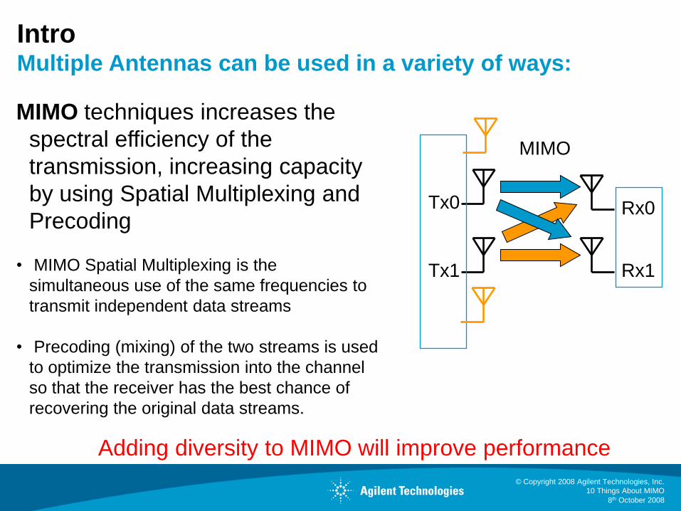
IntroMultiple Antennas can be used in a variety of ways:
MIMO techniques increases the
spectral efficiency of the
transmission, increasing capacity
by using Spatial Multiplexing and
Precoding
• MIMO Spatial Multiplexing is the
simultaneous use of the same frequencies to
transmit independent data streams
• Precoding (mixing) of the two streams is used
to optimize the transmission into the channel
so that the receiver has the best chance of
recovering the original data streams.
Adding diversity to MIMO will improve performance
MIMO
Tx0
Tx1
Rx0
Rx1
© Copyright 2008 Agilent Technologies, Inc.
10 Things About MIMO
8th October 2008
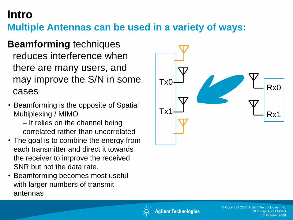
IntroMultiple Antennas can be used in a variety of ways:
Beamforming techniques
reduces interference when
there are many users, and
may improve the S/N in some
cases
• Beamforming is the opposite of Spatial
Multiplexing / MIMO
– It relies on the channel being
correlated rather than uncorrelated
• The goal is to combine the energy from
each transmitter and direct it towards
the receiver to improve the received
SNR but not the data rate.
• Beamforming becomes most useful
with larger numbers of transmit
antennas
Tx0
Tx1
Rx0
Rx1

© Copyright 2008 Agilent Technologies, Inc.
10 Things About MIMO
8th October 2008
Intro
© Copyright 2008 Agilent Technologies, Inc.
10 Things About MIMO
8th October 2008
Intro

© Copyright 2008 Agilent Technologies, Inc.
10 Things About MIMO
8th October 2008
10 Things about MIMO: The Simplified Agenda
System Operation
MIMO signal transmission and recovery
Single and Multiple input measurements

© Copyright 2008 Agilent Technologies, Inc.
10 Things About MIMO
8th October 2008
1: MIMO is Used Differently in the Downlink and
Uplink of a Cellular System
• In the Downlink, it’s like WLAN,
the whole MIMO transmission is
given to a Single User (SU)
• The scheduler in the LTE Base
Station multiplexes user data traffic
into codewords
• If there are more transmitters
available than codewords, layer
mapping is used (layer in LTE =
stream in WiMAX)(Streams)

© Copyright 2008 Agilent Technologies, Inc.
10 Things About MIMO
8th October 2008
MIMO in the Downlink – Coupling in the Channel
• The channel starts
after precoding
• Unwanted coupling in
the radio will introduce
errors in precoding
• The antennas are a
critical part of the
channel
(Streams)

© Copyright 2008 Agilent Technologies, Inc.
10 Things About MIMO
8th October 2008
MIMO in the Downlink - Reception
A single mobile recovers the MIMO transmission via 2 receivers
(Streams)

© Copyright 2008 Agilent Technologies, Inc.
10 Things About MIMO
8th October 2008
MIMO in the Downlink – Closed Loop
Scheduler
•“Precoding” is applied for
closed loop operation
• The mobile measures
the channel to send
reports back to the BS
• The BS decides how to
modify the transmission
CQI, RI, PMI reports

© Copyright 2008 Agilent Technologies, Inc.
10 Things About MIMO
8th October 2008
2: MIMO Operation Requires at Least Two
Transmitters & Two Receivers
• In cellular MIMO, two mobiles are used together in the Uplink to create the MIMO signal
• Known as “Collaborative” MIMO in WiMAX. “Multi-User MIMO” in LTE
• Increased capacity benefit achieved w/lower cost and less battery drain per phone (i.e., 1 TX/phone vs. 2 TX/phone)
The receivers (in a live system) have to be in the same device -
because both signals are needed to calculate the amount of
cross coupling. Transmitters don’t! Hence MU-MIMO possible.

© Copyright 2008 Agilent Technologies, Inc.
10 Things About MIMO
8th October 2008
….at Least Two Transmitters & Two Receivers(e.g., How we measure and verify MIMO precoding)
Freq Ref.
Trig.
Time and Freq
CoherentTime, Freq and Phase
Coherent
x4 BB or RF inputs x2 RF inputs
Infiniium Scope Dual MXAs

© Copyright 2008 Agilent Technologies, Inc.
10 Things About MIMO
8th October 2008
10 Things about MIMO The Agenda
System Operation
MIMO signal transmission and recovery
Single and Multiple input measurements

© Copyright 2008 Agilent Technologies, Inc.
10 Things About MIMO
8th October 2008
3: MIMO Signal Recovery is a Two Step Process
Step 2: Separate and
demodulate the signals
Use High school
simultaneous
equations to
express T0, T1 in
terms of R0, R1
(Real only) examples
values are for a single
OFDM subcarrier at
one instant in timeStep 1: Recover the
channel coefficients
Need a robust signal
format that uniquely
identify each transmitter

© Copyright 2008 Agilent Technologies, Inc.
10 Things About MIMO
8th October 2008
MIMO Signal Recovery
Recovering the channel coefficients via Reference Signals (RS) or Pilots!
In WiMAX and LTE, specific subcarriers are allocated as pilots
Their location is changed from symbol to symbol
Their power is boosted to ensure errors from recovering the
training signal do not dominate the demodulator performance
© Copyright 2008 Agilent Technologies, Inc.
10 Things About MIMO
8th October 2008
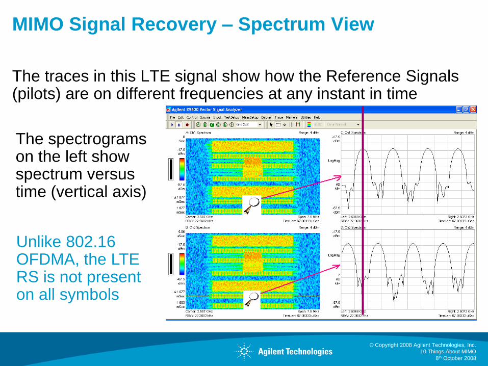
MIMO Signal Recovery – Spectrum View
The traces in this LTE signal show how the Reference Signals (pilots) are on different frequencies at any instant in time
The spectrograms on the left show spectrum versus time (vertical axis)
Unlike 802.16 OFDMA, the LTE RS is not present on all symbols

© Copyright 2008 Agilent Technologies, Inc.
10 Things About MIMO
8th October 2008
Channel Training Signals Vary with Technology
LTE WiMAX Wireless LAN
Reference signals
(pilots) use different
subcarriers for each
transmitter
The QPSK Reference
signals are
transmitted every 3rd
or 4th symbol, mixed
with data
BPSK Pilot subcarriers use
different frequencies. Their
positions vary symbol by
symbol within a subframe,
but are constant from frame
to frame.
Subcarrier coverage builds
over several symbols,
allowing interpolation
Details depend on the zone
type (e.g. PUSC, AMC)
A preamble is used for
training. The same
subcarriers are used for
all transmitters. Signals
are separated by a
CDMA code
4 orthogonal QPSK
pilots are used (6 for
40MHz), sharing the
same subcarriers. They
are never transmitted
without data
HSPA+ uses code channels on the Common Pilot Channel, CPICH, with
unique symbol bit patterns having different locations in the OVSF code domain
Summary Table

© Copyright 2008 Agilent Technologies, Inc.
10 Things About MIMO
8th October 2008
4: Transmit & Receive Phase Differences Don’t
Affect Open Loop MIMO
Open Loop MIMO is a direct mapping technique
(Streams)
• In Open Loop MIMO, the
communications channel does not utilize
explicit information regarding the
propagation channel.
• Common Open Loop MIMO
techniques include Space Time Block
Coding (STBC), Spatial Multiplexing
(SM-MIMO) and Collaborative Uplink
MIMO.
• In WiMAX systems MIMO Matrix A
refers to the STBC technique and MIMO
Matrix B refers to the SM-MIMO
technique.
• Beamforming is an example of Closed
Loop MIMO via Channel feedback to the
TX

© Copyright 2008 Agilent Technologies, Inc.
10 Things About MIMO
8th October 2008
Phase Differences
+ =
Summing different (e.g., pilots) signals the first time does
not affect the individual components
Phase only matters if you couple the same signals
Consider the case of an individual OFDM subcarrier (pilot)

© Copyright 2008 Agilent Technologies, Inc.
10 Things About MIMO
8th October 2008
Phase Differences
+ =
but summing common signals
leads to vector addition
As may the case in Closed Loop MIMO (i.e., Beamforming)

© Copyright 2008 Agilent Technologies, Inc.
10 Things About MIMO
8th October 2008
Application to Test Limits of Receiver Performance
Combine the coded signal with controlled impairments using the signal generators
• Differences in amplitude
• Timing Offset
• Frequency offsets
• Phase Noise
Remember: Phase and Small Frequency
Differences and Time Offsets are removed by
the Tracking Processes in the Demodulator

© Copyright 2008 Agilent Technologies, Inc.
10 Things About MIMO
8th October 2008
N5182A Option 012: Phase Coherence Capability
This configuration
has the flexibility to
expand to 3 or 4
generators
Using separate
generators, there is
no constraint on RF
frequency range
Timing synchronization is dealt with by instrument firmware

© Copyright 2008 Agilent Technologies, Inc.
10 Things About MIMO
8th October 2008
5: BS and MS Antenna Configuration Has a Big
Impact on the Channel Path Correlation
Path correlation defines the coupling relationship between
signals received at the antennas
It is important because it affects how easy or difficult it is to
recover the individual codewords (data streams)
Each multipath item
can have its own
correlation factors

© Copyright 2008 Agilent Technologies, Inc.
10 Things About MIMO
8th October 2008
BS and MS Antenna Configuration Impact
Example: The angle of departure from the BS antennas is
typically narrower than the angle of arrival at the MS
This gives the MS
receivers the
possibility of
recovering different
signals even if the
antennas are closely
spaced

© Copyright 2008 Agilent Technologies, Inc.
10 Things About MIMO
8th October 2008
BS and MS Antenna Configuration and Correlation
The antenna configuration and correlation “type” determine the
correlation matrices
In this example, there
are 6 paths, each with
complex cross
coupling coefficients
Path 1
Path 6
Path 2

© Copyright 2008 Agilent Technologies, Inc.
10 Things About MIMO
8th October 2008
Impact of Antenna Configuration on Correlation
High Correlation
Low Correlation

© Copyright 2008 Agilent Technologies, Inc.
10 Things About MIMO
8th October 2008
N5106A PXB MIMO Receiver Tester
The flexibility of the PXB is used to verify receiver performance
throughout the design cycle, at baseband or RF
Page 31
RF
Analog I/Q- Direct from PXB
- Connect to any DUT or RF
vector signal generator
with analog I/Q inputs
RF
Digital I/Q
Signal OutputsSignal Inputs Signal Creation Tools
ESG or MXGPXB
MXA
N5102A

© Copyright 2008 Agilent Technologies, Inc.
10 Things About MIMO
8th October 2008
Channel Matrix Condition Number Why it is important:
a) A way to check your MIMO system is functioning correctly
b) A short term indication of the CNR you need to recover a MIMO signal
c) If the condition number is larger than the CNR of the signal, it is likely that
MIMO separation of the multiple data streams will not work correctly.
How you calculate it: Find the singular values of the channel matrix, and
take the ratio of the highest / lowest
Simple examples:
A good channel A poor channel
© Copyright 2008 Agilent Technologies, Inc.
10 Things About MIMO
8th October 2008
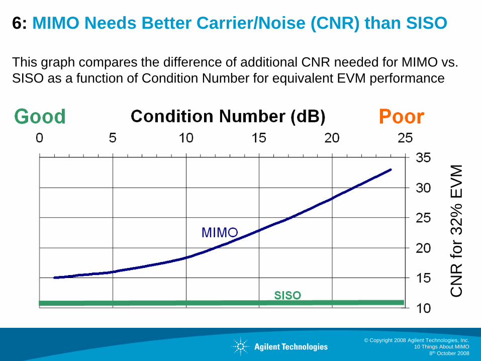
6: MIMO Needs Better Carrier/Noise (CNR) than SISO
This graph compares the difference of additional CNR needed for MIMO vs.
SISO as a function of Condition Number for equivalent EVM performance
CN
R f
or
32%
EV
M

© Copyright 2008 Agilent Technologies, Inc.
10 Things About MIMO
8th October 2008
MIMO Needs Better CNR than SISO
Example: MIMO Signal w/Condition Number = 10 requires ~7dB
more (better) CNR than SISO for same EVM
CN
R f
or
32%
EV
M
~7dB

© Copyright 2008 Agilent Technologies, Inc.
10 Things About MIMO
8th October 2008
Example of MIMO versus SISO performance
Introduce a delay in a static channel to make the
channel condition number vary with frequency
With a constant
CNR, EVM gets
worse as condition
number increases
Better not to use
these subcarriers
for MIMO

© Copyright 2008 Agilent Technologies, Inc.
10 Things About MIMO
8th October 2008
7: Precoding and Eigenbeamforming Couple the
Transmit Signals to Suit the Channel
Precoding can be very simple (LTE Codebook 0 is Direct Mapped)
Some WLAN devices always apply Spatial Expansion
(Eigen) beamforming is the general case, where the channel coefficients are mapped with higher resolution

© Copyright 2008 Agilent Technologies, Inc.
10 Things About MIMO
8th October 2008
The Reality of Precoding in 3GPP LTE
Ripped from3GPP TS 36.211
V8.1.0(2007-11)

© Copyright 2008 Agilent Technologies, Inc.
10 Things About MIMO
8th October 2008
10 Things The Agenda
System Operation
MIMO signal transmission and recovery
Single and Multiple input measurements

© Copyright 2008 Agilent Technologies, Inc.
10 Things About MIMO
8th October 2008
8: Cross Channel Measurements Can Be Made
With a Single Input Analyzer
The Reference signals
(pilots) uniquely identify
each transmitter
We use this to allow
measurements on each
separately
In LTE, the RS are not precoded. These measurements
continue to work even when the signal is not direct mapped

© Copyright 2008 Agilent Technologies, Inc.
10 Things About MIMO
8th October 2008
Cross Channel Timing & Phase Measurement
using a Power Combiner & Single Input
Using a power combiner removes ANY uncertainty due to
timing jitter or calibration
The demodulation process recovers
the time and phase relationship
between the transmitters at the power
combiner input
Cable calibration may still be required

© Copyright 2008 Agilent Technologies, Inc.
10 Things About MIMO
8th October 2008
© Copyright 2008 Agilent Technologies, Inc.
10 Things About MIMO
8th October 2008
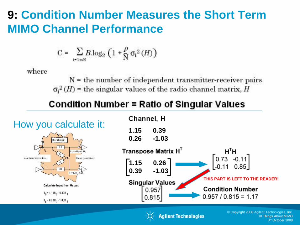
9: Condition Number Measures the Short Term
MIMO Channel Performance
How you calculate it:1.15 0.39
0.26 -1.03
1.15 0.26
0.39 -1.03THIS PART IS LEFT TO THE READER!

© Copyright 2008 Agilent Technologies, Inc.
10 Things About MIMO
8th October 2008
Three channel samples at different times during the fading profile
Lower overall condition number results in a tighter constellation
Ped. B Channel Condition number measurements
© Copyright 2008 Agilent Technologies, Inc.
10 Things About MIMO
8th October 2008
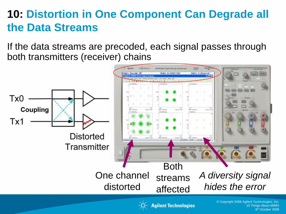
10: Distortion in One Component Can Degrade all
the Data Streams
If the data streams are precoded, each signal passes through both transmitters (receiver) chains
One channel
distorted
Both
streams
affected
A diversity signal
hides the error
© Copyright 2008 Agilent Technologies, Inc.
10 Things About MIMO
8th October 2008
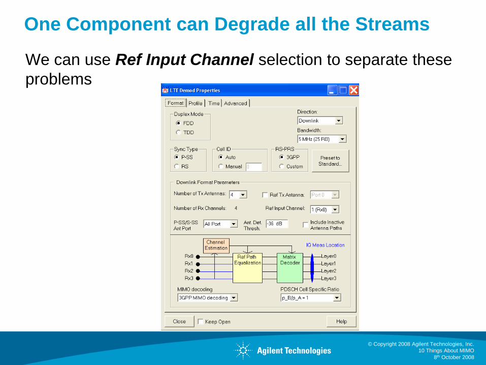
One Component can Degrade all the Streams
We can use Ref Input Channel selection to separate these
problems

© Copyright 2008 Agilent Technologies, Inc.
10 Things About MIMO
8th October 2008
Summary
Intro
System Operation
1: Cellular MIMO uses downlink and uplink differently
2: MIMO needs at least 2 transmitters and 2 receivers
MIMO signal transmission and recovery
3: MIMO signal recovery is a 2 step process
4: Transmit & receive phase differences don’t affect open loop MIMO
5: BS and MS antenna configuration has a big impact on path correlation
6: MIMO needs a better SNR than SISO
7: Precoding and eigenbeamforming couple the signals to suit the channel
Single and Multiple input measurements
8: Cross channel measurements can be made with a single input analyzer
9: Condition number measures the short term channel performance
10: Distortion in one component can degrade all the data streams

© Copyright 2008 Agilent Technologies, Inc.
10 Things About MIMO
8th October 2008
The Poster – Summarizes today’s presentation

© Copyright 2008 Agilent Technologies, Inc.
10 Things About MIMO
8th October 2008
Additional Resources
www.agilent.com/find/mimo
MIMO WLAN PHY layer Operation and Measurement AN1509
http://cp.literature.agilent.com/litweb/pdf/5989-3443EN.pdf
Video: “Single-channel measurements for WiMAX matrix A and B”
http://wireless.agilent.com/vcentral/viewvideo.aspx?vid=366
“WiMAX Wave 2 Testing - MIMO & STC” Agilent webcast 17 Jan 2008
http://www.techonline.com/learning/livewebinar/204203534

© Copyright 2008 Agilent Technologies, Inc.
10 Things About MIMO
8th October 2008
Questions?
“Excuse me, is this the Society for
Asking Stupid Questions?”
www/agilent.com/find/4GWorld


