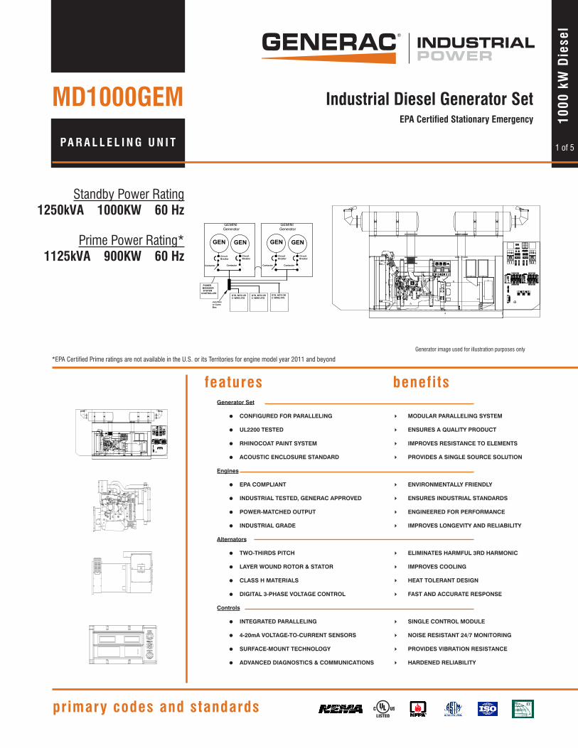
1 of 5 Standby Power Rating 1250kVA 1000KW 60 Hz Prime Power Rating* 1125kVA 900KW 60 Hz features benefits primary codes and standards 1000 kW Diesel Industrial Diesel Generator Set EPA Certified Stationary Emergency Generator image used for illustration purposes only *EPA Certified Prime ratings are not available in the U.S. or its Territories for engine model year 2011 and beyond Generator Set = CONFIGURED FOR PARALLELING 4 MODULAR PARALLELING SYSTEM = UL2200 TESTED 4 ENSURES A QUALITY PRODUCT = RHINOCOAT PAINT SYSTEM 4 IMPROVES RESISTANCE TO ELEMENTS = ACOUSTIC ENCLOSURE STANDARD 4 PROVIDES A SINGLE SOURCE SOLUTION Engines = EPA COMPLIANT 4 ENVIRONMENTALLY FRIENDLY = INDUSTRIAL TESTED, GENERAC APPROVED 4 ENSURES INDUSTRIAL STANDARDS = POWER-MATCHED OUTPUT 4 ENGINEERED FOR PERFORMANCE = INDUSTRIAL GRADE 4 IMPROVES LONGEVITY AND RELIABILITY Alternators = TWO-THIRDS PITCH 4 ELIMINATES HARMFUL 3RD HARMONIC = LAYER WOUND ROTOR & STATOR 4 IMPROVES COOLING = CLASS H MATERIALS 4 HEAT TOLERANT DESIGN = DIGITAL 3-PHASE VOLTAGE CONTROL 4 FAST AND ACCURATE RESPONSE Controls = INTEGRATED PARALLELING 4 SINGLE CONTROL MODULE = 4-20mA VOLTAGE-TO-CURRENT SENSORS 4 NOISE RESISTANT 24/7 MONITORING = SURFACE-MOUNT TECHNOLOGY 4 PROVIDES VIBRATION RESISTANCE = ADVANCED DIAGNOSTICS & COMMUNICATIONS 4 HARDENED RELIABILITY PARALLELING UNIT MD1000GEM GEN GEMINI Generator GEN GEN GEN GEMINI Generator Circuit Breaker Contactor Circuit Breaker Contactor Circuit Breaker Contactor Circuit Breaker Contactor POWER MANAGER SYSTEM CONTROLLER GTS, MTS OR 2- WIRE ATS GTS, MTS OR 2- WIRE ATS GTS, MTS OR 2- WIRE ATS Junction or Conn Box
PUSH THE "TRIP" WITH A SCREWDRIVEROPERATE IN THE DIRECTIONSET MANUAL HANDLE ON "M" AND
AT2
600 VAC CSA480 VAC UL
1000A
M
T
S1B
TRIP OPENCLOSE
S1A A2AT1 A1
TRIP
CLOSE MANUAL
XXXXX
OFF
RATED VOLTAGE
RATED CURRENTLOAD BREAK SWITCH
xxxxxx
DO NOT OPERATE WHILE THE SWITCH IS UNDER LOAD.
PUSH THE "TRIP" WITH A SCREWDRIVEROPERATE IN THE DIRECTIONSET MANUAL HANDLE ON "M" AND
AT2
600 VAC CSA480 VAC UL
1000A
M
T
S1B
TRIP OPENCLOSE
S1A A2AT1 A1
HzS
E
RGENERACPOW TEMSINC.YS
LS-8 CLASS 0.5
0
277V56
55 65
64
E
RSYSTEMSINC.GENERACPOW
600
500100
LS-8 CLASS 1.5
V0
58
6062400200
300
SWGENERACPO
E
RSYSTEMINC.
LS-8 CLASS 1.5CT. 100:5A
A
0 1600
1200
800
400
ALARM
NOT IN AUTONOT IN AUTO
GENERATOR
AUTO OFF MAN.ALARMCONTROL UNIT B
ALARM
EMERGENCYSTOPUNIT A
ALARMCONTROL
GENERATOR
AUTO OFF MAN.
0E9157B
PA R A L L E L I N G U N I T
MD1000GEM
1 42 3 5 6 7 98 10 1211
0C51
39
0C51
37
12 13
24
5
1110
98
LARG
E B
LAC
K67
1211
109
8
1212 1 12
34
5
0C51
40
8 5
9 4
1110 3
2 0D53
18
1110
98
SMA
LL G
RAY
LARG
E G
RAY 6 77 6 7
13
24
5
LARG
E B
ROW
N6
1 42 3 5 6 7 98 10 1211
P/N:055911
0D53
18
12 12 11
8 5
9 4
1110 3
20C51
37
1110
98
32
45
0C51
39
LARG
E B
LAC
K
LARG
E G
RAY
7 67 6
1212 1
1110
98
0C51
40
11 12
10 39 4
8 5
32
45
LARG
E B
ROW
N
SMA
LL G
RAY 77 6 6
3 4
2 1
643 55 6
712 88 7
23
LO HI
67
4 5
LO
32
HI
67
LO
32
54 54
HI
67
ON
23
LO HI
67
4 5
LO
32
HI
67
LO
32
54 54
HI
67
ON
TRIP
CLOSE MANUAL
XXXXX
OFF
RATED VOLTAGE
RATED CURRENTLOAD BREAK SWITCH
xxxxxx
DO NOT OPERATE WHILE THE SWITCH IS UNDER LOAD.
PUSH THE "TRIP" WITH A SCREWDRIVEROPERATE IN THE DIRECTIONSET MANUAL HANDLE ON "M" AND
AT2
600 VAC CSA480 VAC UL
1000A
M
T
S1B
TRIP OPENCLOSE
S1A A2AT1 A1
TRIP
CLOSE MANUAL
XXXXX
OFF
RATED VOLTAGE
RATED CURRENTLOAD BREAK SWITCH
xxxxxx
DO NOT OPERATE WHILE THE SWITCH IS UNDER LOAD.
PUSH THE "TRIP" WITH A SCREWDRIVEROPERATE IN THE DIRECTIONSET MANUAL HANDLE ON "M" AND
AT2
600 VAC CSA480 VAC UL
1000A
M
T
S1B
TRIP OPENCLOSE
S1A A2AT1 A1
HzS
E
RGENERACPOW TEMSINC.YS
LS-8 CLASS 0.5
0
277V56
55 65
64
E
RSYSTEMSINC.GENERACPOW
600
500100
LS-8 CLASS 1.5
V0
58
6062400200
300
SWGENERACPO
E
RSYSTEMINC.
LS-8 CLASS 1.5CT. 100:5A
A
0 1600
1200
800
400
ALARM
NOT IN AUTONOT IN AUTO
GENERATOR
AUTO OFF MAN.ALARMCONTROL UNIT B
ALARM
EMERGENCYSTOPUNIT A
ALARMCONTROL
GENERATOR
AUTO OFF MAN.
0E9157B
GEN
Cir Brk
GEMINI Generator
GEN
Contactor
Diesel Generator Diesel Generator
ContactorContactor
CircuitBreaker
CircuitBreaker
Diesel Generator
GEN GEN
CircuitBreaker
GEN
UTILITY
ATS
UTILITY
ATS ATS
UTILITY
GEN GEN
GEMINIGenerator
CircuitBreaker
Contactor
CircuitBreaker
Contactor
CircuitBreaker
Contactor
CircuitBreaker
Contactor
POWER MANAGER SYSTEM CONTROLLER
GTS, MTS OR 2- WIRE ATS
GTS, MTS OR 2- WIRE ATS
GTS, MTS OR 2- WIRE ATS
Junction or ConnBox
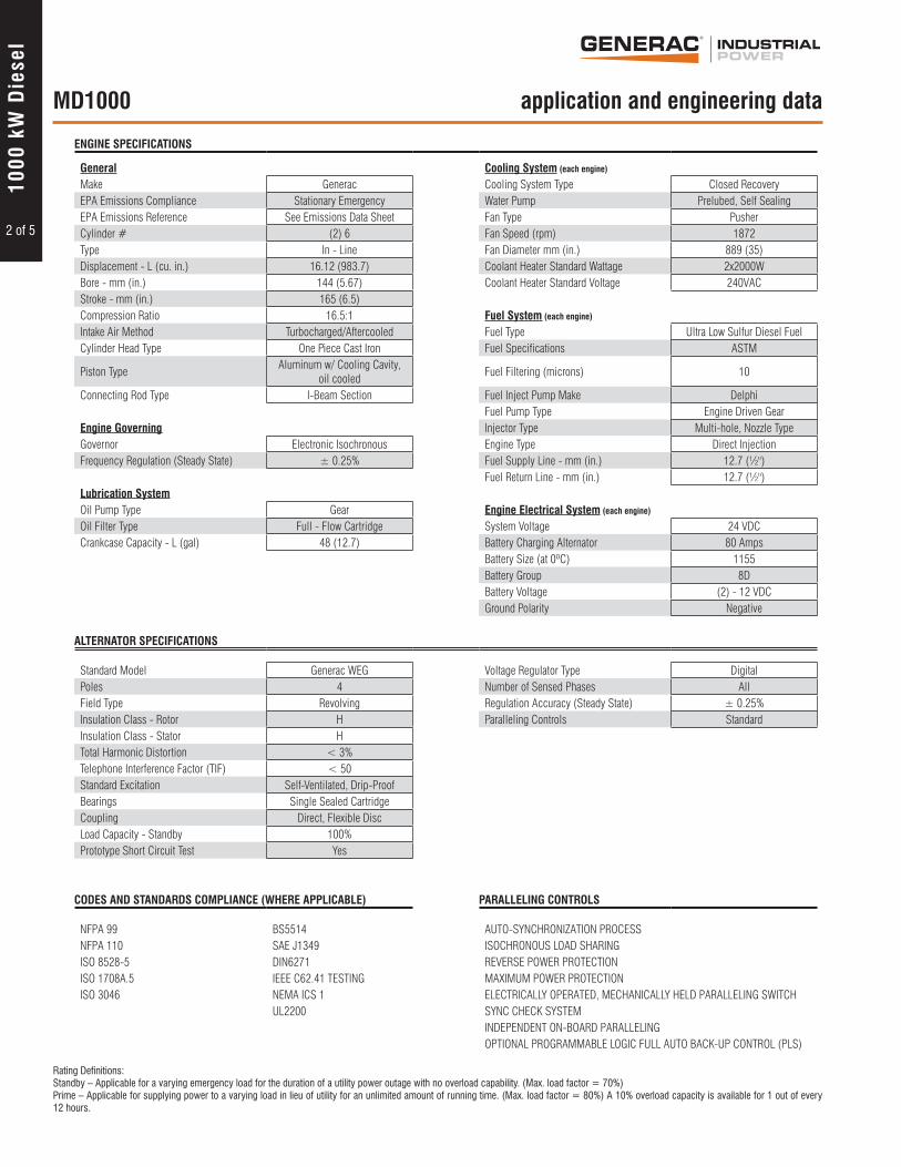
ENGINE SPECIFICATIONS
General Cooling System (each engine)
Make Generac Cooling System Type Closed RecoveryEPA Emissions Compliance Stationary Emergency Water Pump Prelubed, Self SealingEPA Emissions Reference See Emissions Data Sheet Fan Type PusherCylinder # (2) 6 Fan Speed (rpm) 1872Type In - Line Fan Diameter mm (in.) 889 (35)Displacement - L (cu. in.) 16.12 (983.7) Coolant Heater Standard Wattage 2x2000WBore - mm (in.) 144 (5.67) Coolant Heater Standard Voltage 240VACStroke - mm (in.) 165 (6.5)Compression Ratio 16.5:1 Fuel System (each engine)
Intake Air Method Turbocharged/Aftercooled Fuel Type Ultra Low Sulfur Diesel FuelCylinder Head Type One Piece Cast Iron Fuel Specifications ASTM
Piston TypeAluminum w/ Cooling Cavity,
oil cooledFuel Filtering (microns) 10
Connecting Rod Type I-Beam Section Fuel Inject Pump Make DelphiFuel Pump Type Engine Driven Gear
Engine Governing Injector Type Multi-hole, Nozzle TypeGovernor Electronic Isochronous Engine Type Direct InjectionFrequency Regulation (Steady State) ± 0.25% Fuel Supply Line - mm (in.) 12.7 (½")
Fuel Return Line - mm (in.) 12.7 (½")Lubrication SystemOil Pump Type Gear Engine Electrical System (each engine)
Oil Filter Type Full - Flow Cartridge System Voltage 24 VDCCrankcase Capacity - L (gal) 48 (12.7) Battery Charging Alternator 80 Amps
Battery Size (at 0ºC) 1155Battery Group 8DBattery Voltage (2) - 12 VDCGround Polarity Negative
ALTERNATOR SPECIFICATIONS
Standard Model Generac WEG Voltage Regulator Type DigitalPoles 4 Number of Sensed Phases AllField Type Revolving Regulation Accuracy (Steady State) ± 0.25%Insulation Class - Rotor H Paralleling Controls StandardInsulation Class - Stator HTotal Harmonic Distortion < 3%Telephone Interference Factor (TIF) < 50Standard Excitation Self-Ventilated, Drip-ProofBearings Single Sealed CartridgeCoupling Direct, Flexible DiscLoad Capacity - Standby 100%Prototype Short Circuit Test Yes
CODES AND STANDARDS COMPLIANCE (WHERE APPLICABLE) PARALLELING CONTROLS
NFPA 99 BS5514 AUTO-SYNCHRONIZATION PROCESSNFPA 110 SAE J1349 ISOCHRONOUS LOAD SHARINGISO 8528-5 DIN6271 REVERSE POWER PROTECTIONISO 1708A.5 IEEE C62.41 TESTING MAXIMUM POWER PROTECTIONISO 3046 NEMA ICS 1 ELECTRICALLY OPERATED, MECHANICALLY HELD PARALLELING SWITCH
UL2200 SYNC CHECK SYSTEMINDEPENDENT ON-BOARD PARALLELINGOPTIONAL PROGRAMMABLE LOGIC FULL AUTO BACK-UP CONTROL (PLS)
2 of 5
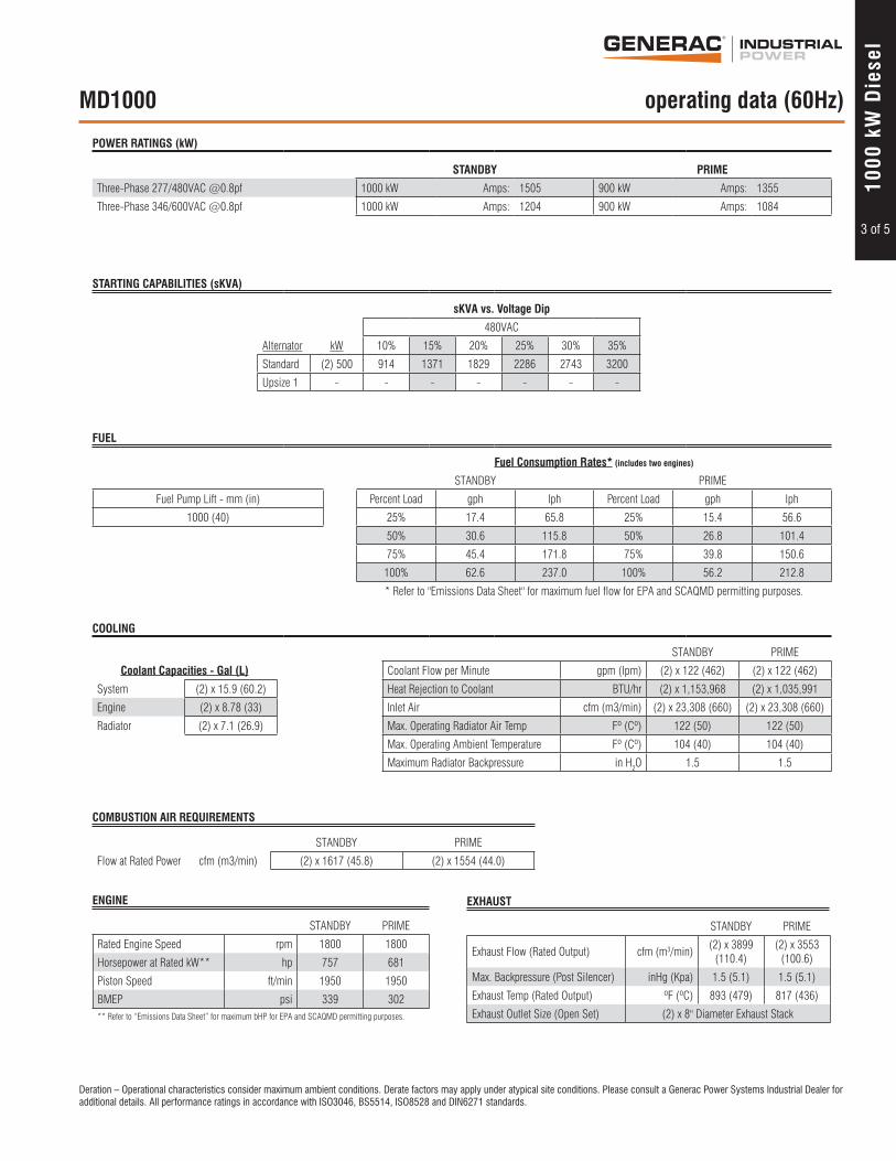
Rating Definitions:Standby – Applicable for a varying emergency load for the duration of a utility power outage with no overload capability. (Max. load factor = 70%) Prime – Applicable for supplying power to a varying load in lieu of utility for an unlimited amount of running time. (Max. load factor = 80%) A 10% overload capacity is available for 1 out of every 12 hours.
Deration – Operational characteristics consider maximum ambient conditions. Derate factors may apply under atypical site conditions. Please consult a Generac Power Systems Industrial Dealer for additional details. All performance ratings in accordance with ISO3046, BS5514, ISO8528 and DIN6271 standards.
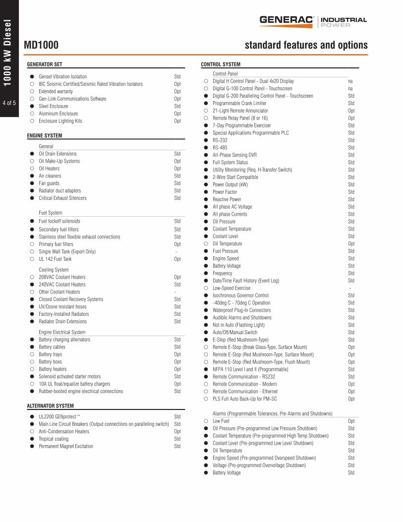
� UL2200 GENprotect™ Std� Main Line Circuit Breakers (Output connections on paralleling switch) Std� Anti-Condensation Heaters Opt� Tropical coating Std� Permanent Magnet Excitation Std
CONTROL SYSTEM
Control Panel� Digital H Control Panel - Dual 4x20 Display na� Digital G-100 Control Panel - Touchscreen na� Digital G-200 Paralleling Control Panel - Touchscreen Std� Programmable Crank Limiter Std� 21-Light Remote Annunciator Opt� Remote Relay Panel (8 or 16) Opt� 7-Day Programmable Exerciser Std� Special Applications Programmable PLC Std� RS-232 Std� RS-485 Std� All-Phase Sensing DVR Std� Full System Status Std� Utility Monitoring (Req. H-Transfer Switch) Std� 2-Wire Start Compatible Std� Power Output (kW) Std� Power Factor Std� Reactive Power Std� All phase AC Voltage Std� All phase Currents Std� Oil Pressure Std� Coolant Temperature Std� Coolant Level Std� Oil Temperature Opt� Fuel Pressure Std� Engine Speed Std� Battery Voltage Std� Frequency Std� Date/Time Fault History (Event Log) Std� Low-Speed Exercise - � Isochronous Governor Control Std� -40deg C - 70deg C Operation Std� Waterproof Plug-In Connectors Std� Audible Alarms and Shutdowns Std� Not in Auto (Flashing Light) Std� Auto/Off/Manual Switch Std� E-Stop (Red Mushroom-Type) Std� Remote E-Stop (Break Glass-Type, Surface Mount) Opt� Remote E-Stop (Red Mushroom-Type, Surface Mount) Opt� Remote E-Stop (Red Mushroom-Type, Flush Mount) Opt� NFPA 110 Level I and II (Programmable) Std� Remote Communication - RS232 Std� Remote Communication - Modem Opt� Remote Communication - Ethernet Opt� PLS Full Auto Back-Up for PM-SC Opt
Alarms (Programmable Tolerances, Pre-Alarms and Shutdowns)
� Low Fuel Opt� Oil Pressure (Pre-programmed Low Pressure Shutdown) Std� Coolant Temperature (Pre-programmed High Temp Shutdown) Std� Coolant Level (Pre-programmed Low Level Shutdown) Std� Oil Temperature Std� Engine Speed (Pre-programmed Overspeed Shutdown) Std� Voltage (Pre-programmed Overvoltage Shutdown) Std� Battery Voltage Std
4 of 5
MD1000 standard features and options
1000
kW
Die
sel
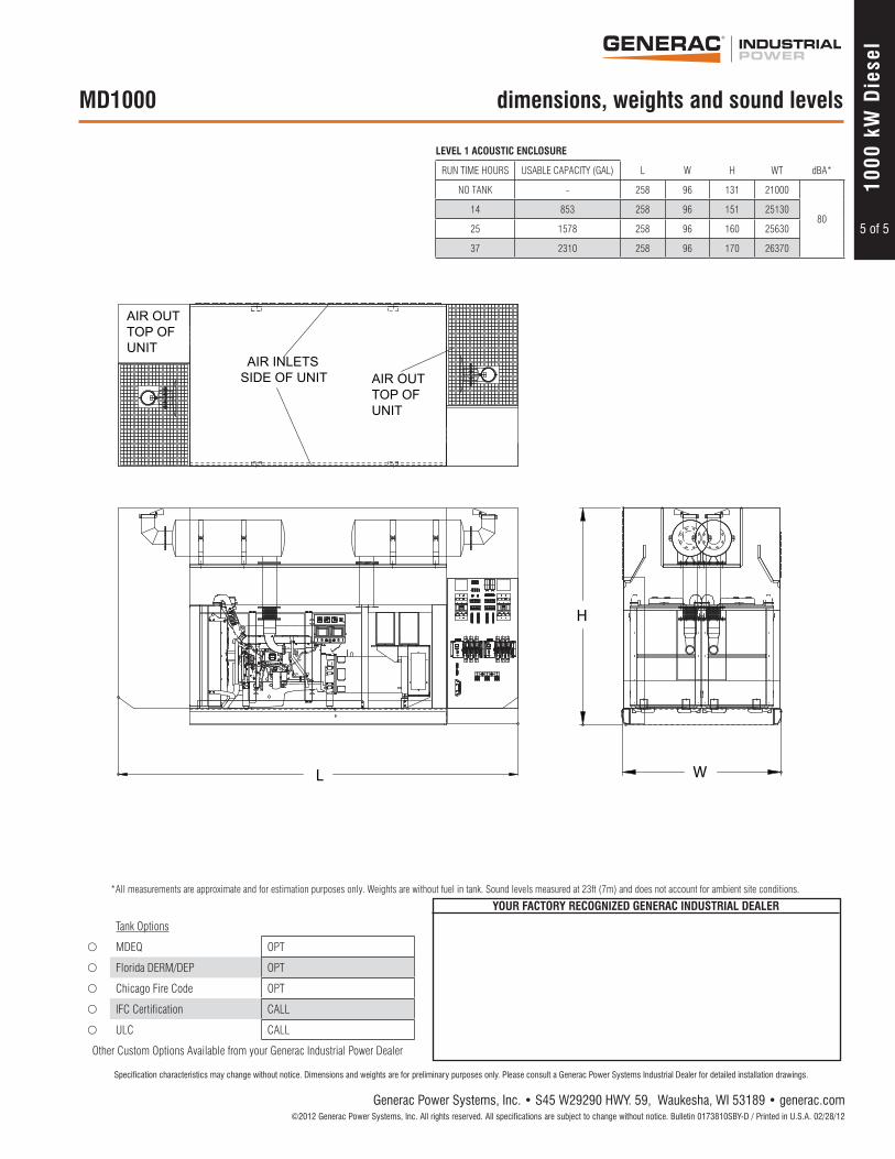
LEVEL 1 ACOUSTIC ENCLOSURE
RUN TIME HOURS USABLE CAPACITY (GAL) L W H WT dBA*
NO TANK - 258 96 131 21000
8014 853 258 96 151 25130
25 1578 258 96 160 25630
37 2310 258 96 170 26370
Tank Options
� MDEQ OPT
� Florida DERM/DEP OPT
� Chicago Fire Code OPT
� IFC Certification CALL
� ULC CALL
Other Custom Options Available from your Generac Industrial Power Dealer
* All measurements are approximate and for estimation purposes only. Weights are without fuel in tank. Sound levels measured at 23ft (7m) and does not account for ambient site conditions.
1 42 3 5 6 7 98 10 1211
0C51
39
0C51
37
12 13
24
5
1110
98
LARG
E BL
AC
K67
1211
109
8
1212 1 12
34
5
0C51
40
8 5
9 4
1110 3
2 0D53
18
1110
98
SMA
LL G
RAY
LARG
E G
RAY 6 77 6 7
13
24
5
LARG
E BR
OW
N6
1 42 3 5 6 7 98 10 1211
P/N:055911
0D53
18
12 12 11
8 5
9 4
1110 3
20C51
37
1110
98
32
45
0C51
39
LARG
E BL
AC
K
LARG
E G
RAY7 67 6
1212 1
1110
98
0C51
40
11 12
10 39 4
8 5
32
45
LARG
E BR
OW
N
SMA
LL G
RAY 77 6 6
3 4
2 1
643 55 6
712 88 7
23
LO HI
67
4 5
LO
32
HI
67
LO
32
54 54
HI
67
ON
23
LO HI
67
4 5
LO
32
HI
67
LO
32
54 54
HI
67
ON
TRIP
CLOSE MANUAL
XXXXX
OFF
RATED VOLTAGE
RATED CURRENTLOAD BREAK SWITCH
xxxxxx
DO NOT OPERATE WHILE THE SWITCH IS UNDER LOAD.
PUSH THE "TRIP" WITH A SCREWDRIVEROPERATE IN THE DIRECTIONSET MANUAL HANDLE ON "M" AND
AT2
600 VAC CSA480 VAC UL
1000A
M
T
S1B
TRIP OPENCLOSE
S1A A2AT1 A1
TRIP
CLOSE MANUAL
XXXXX
OFF
RATED VOLTAGE
RATED CURRENTLOAD BREAK SWITCH
xxxxxx
DO NOT OPERATE WHILE THE SWITCH IS UNDER LOAD.
PUSH THE "TRIP" WITH A SCREWDRIVEROPERATE IN THE DIRECTIONSET MANUAL HANDLE ON "M" AND
Specification characteristics may change without notice. Dimensions and weights are for preliminary purposes only. Please consult a Generac Power Systems Industrial Dealer for detailed installation drawings.