Model NumberSerial NumberDate PurchasedRetailer / Qualified Installer
INSTALLATIONINSTRUCTIONS
MODEL200(XX)(XX).003(#)
Read these instructions carefully. These instructions MUST stay with this product.
2
Required hardware:8′ - 13′ Models:(1) Mounting Bracket(12) M6 X 50 mm L Carriage Bolt(12) M6 Split Lock Washer(12) M6 Flat Washer(12) M6 Locknut With Nylon Insert(6) #8-18 X .38 Self Drilling Flat Head Screw
Additional hardware quantities:15′ - 16′ Models ONLY:(4) M6 X 50 mm L Carriage Bolt(4) M6 Split Lock Washer(4) M6 Flat Washer(4) M6 Locknut With Nylon Insert(2) #8-18 X .38 Self Drilling Flat Head Screw
Required tools:3 mm Hex Key6 mm Hex KeyTorque Wrench6 mm Hex Key Socket10 mm SocketPH Phillips Head Screwdriver (or bit and drill)
Optional accessories:3313887.000 Kit, Support Leg3313885.000 Kit, Tie Down Strap
A. ApplicationThis awning (hereinafter referred to as “product” or “aw-ning”) is ideal for use on RVs. It is especially well suited for RVs with an over cab extension where there is not sufficient surface for a bottom mounting bracket. This awning can be installed by one person with brief help from additional personnel. Use the following procedure to ensure a properly installed, and properly functioning awning.
Dometic, LLC reserves the right to modify appearances and specifications without notice.
Read and understand these instructions before installing this product. Incorrect in-stallation can lead to serious injury. Follow all installation instructions. This product MUST be installed by a Dometic, LLC Ser-vice Center or a qualified service technician. Do NOT modify this product in any way. Modi-fication can be extremely hazardous. Failure to obey these warnings could result in death or serious injury.
WARNING
IMPORTANT SAFETY INSTRUCTIONS
This manual has safety information and instruc-tions to help users eliminate or reduce the risk of accidents and injuries.
RECOGNIZE SAFETY INFORMATION
This is the safety alert symbol. It is used to alert you to personal injury hazards. Obey all safety messages that follow this symbol to avoid pos-sible injury or death.
UNDERSTAND SIGNAL WORDS
A signal word, when used with the safety alert symbol, will identify a safety hazard and its level of risk for personal injury. A signal word, without the safety alert symbol, will be used for property damage messages only.
WARNING indicates a hazard-ous situation which, if not avoided, could result in death or serious injury.
CAUTION, used with the safe-ty alert symbol, indicates a hazardous situation which, if not avoided, could result in minor or moderate injury.
NOTICE is used to address practices not related to personal injury.
WARNING
NOTICE
CAUTION
GENERAL INSTRUCTIONS
Read and follow all safety information and instructions to avoid possible injury or death.
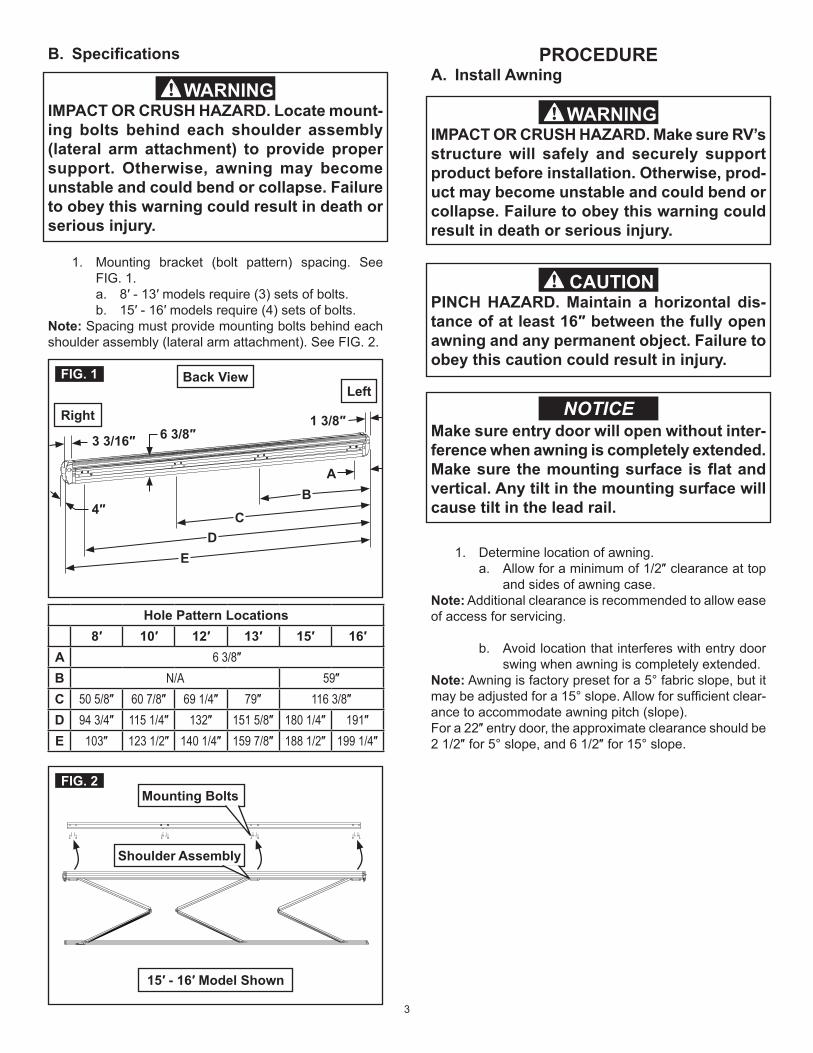
1. Mounting bracket (bolt pattern) spacing. See FIG. 1.a. 8′ - 13′ models require (3) sets of bolts.b. 15′ - 16′ models require (4) sets of bolts.
Note: Spacing must provide mounting bolts behind each shoulder assembly (lateral arm attachment). See FIG. 2.
1. Determine location of awning.a. Allow for a minimum of 1/2″ clearance at top
and sides of awning case.Note: Additional clearance is recommended to allow ease of access for servicing.
b. Avoid location that interferes with entry door swing when awning is completely extended.
Note: Awning is factory preset for a 5° fabric slope, but it may be adjusted for a 15° slope. Allow for sufficient clear-ance to accommodate awning pitch (slope).For a 22″ entry door, the approximate clearance should be 2 1/2″ for 5° slope, and 6 1/2″ for 15° slope.
Make sure entry door will open without inter-ference when awning is completely extended.Make sure the mounting surface is flat and vertical. Any tilt in the mounting surface will cause tilt in the lead rail.
NOTICE
IMPACT OR CRUSH HAZARD. Make sure RV’s structure will safely and securely support product before installation. Otherwise, prod-uct may become unstable and could bend or collapse. Failure to obey this warning could result in death or serious injury.
WARNING
PINCH HAZARD. Maintain a horizontal dis-tance of at least 16″ between the fully open awning and any permanent object. Failure to obey this caution could result in injury.
CAUTION
IMPACT OR CRUSH HAZARD. Locate mount-ing bolts behind each shoulder assembly (lateral arm attachment) to provide proper support. Otherwise, awning may become unstable and could bend or collapse. Failure to obey this warning could result in death or serious injury.
WARNING
4
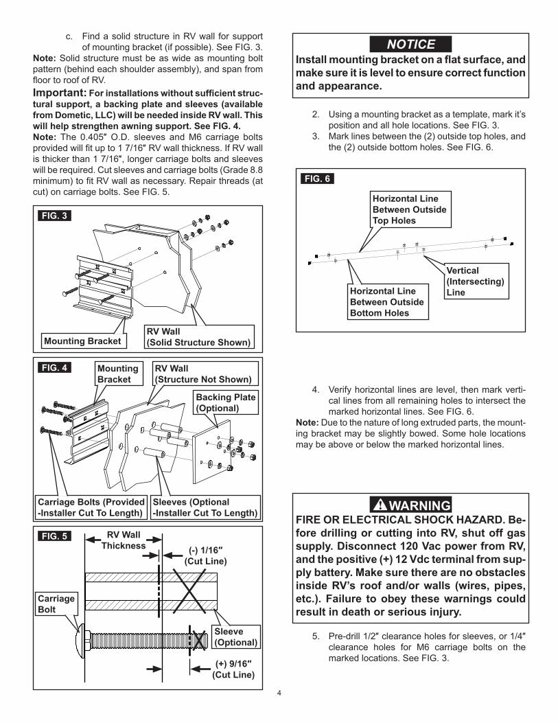
c. Find a solid structure in RV wall for support of mounting bracket (if possible). See FIG. 3.
Note: Solid structure must be as wide as mounting bolt pattern (behind each shoulder assembly), and span from floor to roof of RV.Important: For installations without sufficient struc-tural support, a backing plate and sleeves (available from Dometic, LLC) will be needed inside RV wall. This will help strengthen awning support. See FIG. 4.Note: The 0.405″ O.D. sleeves and M6 carriage bolts provided will fit up to 1 7/16″ RV wall thickness. If RV wall is thicker than 1 7/16″, longer carriage bolts and sleeves will be required. Cut sleeves and carriage bolts (Grade 8.8 minimum) to fit RV wall as necessary. Repair threads (at cut) on carriage bolts. See FIG. 5.
FIG. 5 RV Wall Thickness (-) 1/16″
(Cut Line)
(+) 9/16″(Cut Line)
Carriage Bolt
Sleeve (Optional)
FIG. 4 RV Wall(Structure Not Shown)
Sleeves (Optional-Installer Cut To Length)
Mounting Bracket
Backing Plate (Optional)
Carriage Bolts (Provided-Installer Cut To Length)
FIG. 3
Mounting BracketRV Wall(Solid Structure Shown)
5. Pre-drill 1/2″ clearance holes for sleeves, or 1/4″ clearance holes for M6 carriage bolts on the marked locations. See FIG. 3.
Install mounting bracket on a flat surface, and make sure it is level to ensure correct function and appearance.
NOTICE
2. Using a mounting bracket as a template, mark it’s position and all hole locations. See FIG. 3.
3. Mark lines between the (2) outside top holes, and the (2) outside bottom holes. See FIG. 6.
4. Verify horizontal lines are level, then mark verti-cal lines from all remaining holes to intersect the marked horizontal lines. See FIG. 6.
Note: Due to the nature of long extruded parts, the mount-ing bracket may be slightly bowed. Some hole locations may be above or below the marked horizontal lines.
FIG. 6
Horizontal Line Between Outside Bottom Holes
Horizontal Line Between Outside Top Holes
Vertical (Intersecting) Line
FIRE OR ELECTRICAL SHOCK HAZARD. Be-fore drilling or cutting into RV, shut off gas supply. Disconnect 120 Vac power from RV, and the positive (+) 12 Vdc terminal from sup-ply battery. Make sure there are no obstacles inside RV’s roof and/or walls (wires, pipes, etc.). Failure to obey these warnings could result in death or serious injury.
6
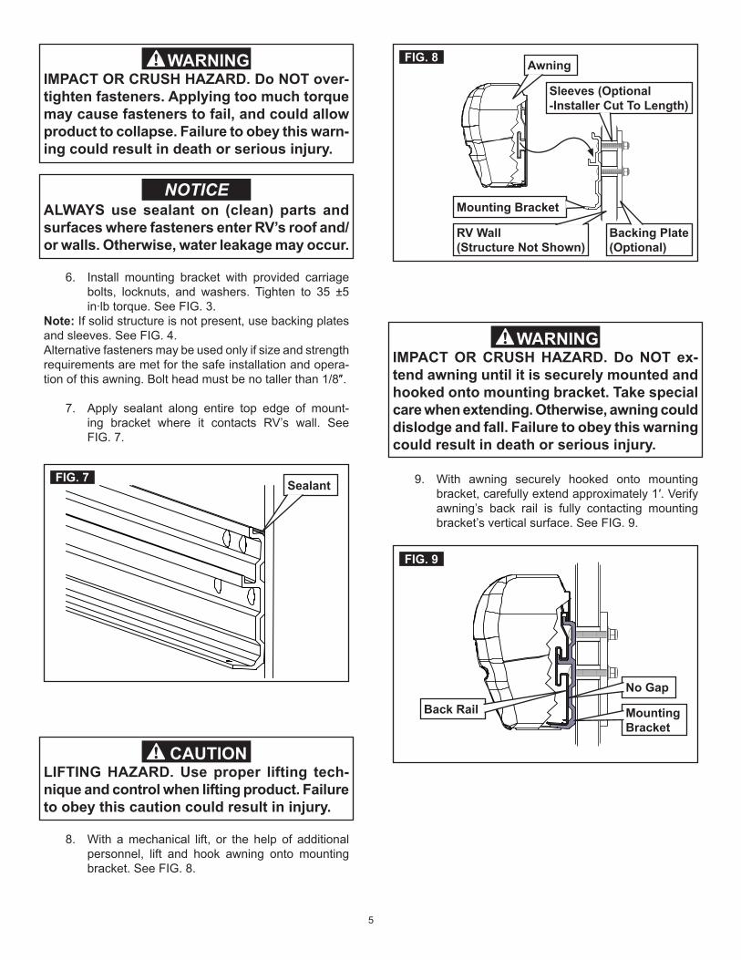
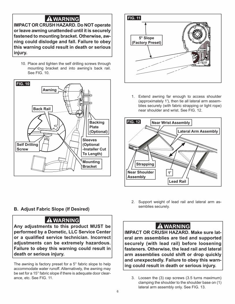
10. Place and tighten the self drilling screws through mounting bracket and into awning’s back rail. See FIG. 10.
FIG. 10
Self Drilling Screw
Backing Plate (Optional)
Awning
Mounting Bracket
Back Rail
Sleeves (Optional -Installer Cut To Length)
B. Adjust Fabric Slope (If Desired)
FIG. 11
5° Slope(Factory Preset)
Any adjustments to this product MUST be performed by a Dometic, LLC Service Center or a qualified service technician. Incorrect adjustments can be extremely hazardous. Failure to obey this warning could result in death or serious injury.
WARNING
The awning is factory preset for a 5° fabric slope to help accommodate water runoff. Alternatively, the awning may be set for a 15° fabric slope if there is adequate door clear-ance, etc. See FIG. 11.
FIG. 12
Lateral Arm Assembly
Strapping
1′Near Shoulder Assembly
Near Wrist Assembly
Lead Rail
1. Extend awning far enough to access shoulder (approximately 1′), then tie all lateral arm assem-blies securely (with fabric strapping or light rope) near shoulder and wrist. See FIG. 12.
2. Support weight of lead rail and lateral arm as-semblies securely.
3. Loosen the (3) cap screws (3.5 turns maximum) clamping the shoulder to the shoulder base on (1) lateral arm assembly only. See FIG. 13.
IMPACT OR CRUSH HAZARD. Make sure lat-eral arm assemblies are tied and supported securely (with lead rail) before loosening fasteners. Otherwise, the lead rail and lateral arm assemblies could shift or drop quickly and unexpectedly. Failure to obey this warn-ing could result in death or serious injury.
WARNING
IMPACT OR CRUSH HAZARD. Do NOT operate or leave awning unattended until it is securely fastened to mounting bracket. Otherwise, aw-ning could dislodge and fall. Failure to obey this warning could result in death or serious injury.
WARNING
7
FIG. 13Shoulder Base
ShoulderLateral Arm Assembly
Cap Screws
5. Tighten cap screws to 140 in·lb torque to re-clamp the shoulder to the shoulder base. See FIG. 13.
6. Repeat steps (3) through (5) for each lateral arm assembly. Remove ties when done.
4. Pivot the lateral arm assembly down (rotate shoulder in shoulder base to lower lead rail) until shoulder’s key aligns with shoulder base’s groove at position “2”. See FIG. 13 and 14.
PINCH POINT HAZARD. Keep clear of pivot area when raising or lowering lateral arm assembly. Failure to obey this caution could result in injury.
CAUTION
1. Extend awning far enough to access shoulder base (approximately 1′). See FIG. 16.
FIG. 16
Shoulder Base
Shoulder Bracket
Cap Screws
Adjustment Screw
C. Readjust Lateral Arm Assemblies (If Re-quired)
After fabric slope adjustment, verify that awning will close without interference. If awning will not close correctly, or if lateral arm assembly’s elbow will not clear back rail, it will need readjustment. See FIG. 15.Note: The lateral arm assembly’s elbow should just clear (slightly above) lower lip of back rail without rubbing. Adjust-ing too high may interfere with top (awning case), or may cause shoulder base to contact awning fabric.
Do NOT allow lateral arm assemblies to rub against lower lip of back rail when closing, or rest on awning fabric when fully opened. Otherwise, premature wear and abrasions could occur.
NOTICE
FIG. 15
Elbow Clearance
Lateral Arm Assembly
Top
Back Rail
Shoulder Base
FIG. 14
123
4
Shoulder’s Key
Shoulder Base
8
IMPACT OR CRUSH HAZARD. Make sure lead rail and lateral arm assemblies are supported securely before loosening fasteners.Do NOT completely remove fasteners, or loosen them so far that shoulder base will disengage from shoulder bracket.Otherwise, the lead rail and lateral arm as-semblies could drop quickly and unexpect-edly, or lateral arm assemblies could extend to the side, beyond awning perimeter quickly and unexpectedly.Failure to obey these warnings could result in death or serious injury.
WARNING
3. Slightly loosen the (2) cap screws (per lateral arm assembly) clamping the shoulder base to the shoulder bracket. See FIG. 16 and 17.
Important: Loosen cap screws just enough to relieve clamping pressure on components. Do NOT loosen any farther.
FIG. 17
Shoulder Base
Shoulder Bracket
Cap Screws
Adjustment Screw
2. Support weight of lead rail and lateral arm as-semblies securely.
D. Realign Lead Rail (If Required)After fabric slope and lateral arm assembly adjustments, the lead rail may need realignment with top and end caps. See FIG. 18.
1. Check alignment of lead rail against top and end caps.
2. Extend awning far enough to access adjustment screw in wrist pivot (approximately 6″).
3. Tilt lead rail, by turning adjustment screw in wrist pivot (for each lateral arm assembly), until align-ment appears correct.a. Turn clockwise to tilt lead rail forward.b. Turn counter-clockwise to tilt lead rail back.
4. Retract awning again to check alignment of lead rail against top and end caps.
5. Repeat steps (2) through (4) as necessary.
FIG. 18
Lead Rail
Wrist PivotLateral Arm Assembly
Top
Adjustment Screw
RH End Cap
Wrist Bracket
c. When you reach appropriate clearance, ex-tend awning far enough to access shoulder base (approximately 1′).
d. Tighten the (2) cap screws to 140 in·lb torque (for each lateral arm assembly) to clamp the shoulder base to the shoulder bracket.
E. Secure Awning For Travel
Examine installation for imbalance; and signs of wear or damage to wiring, cables, and other critical parts. Any adjustments or repairs must be performed by a Dometic, LLC Service Center or a qualified service technician.
WARNING
1. Operate awning according to the Operating In-structions to verify all parts are functioning cor-rectly.
2. Secure awning for travel. (See “Close Awning” in Operating Instructions.)
4. Readjust lateral arm assembly’s closing height. See FIG. 15, 16 and 17.a. Retract awning until lateral arm assembly’s
elbow meets top and back rail to check for clearance.
Note: Allow enough gap to access adjustment screw. See FIG. 17.
b. Turn adjustment screw in shoulder base IN to raise or OUT to lower lateral arm assembly.
Note: This will also affect the lead rail height. See “Realign Lead Rail” section to adjust lead rail alignment.