30
100GbE Architecture - Getting There ... Joel Goergen Chief Scientist April 26, 2005

100GbE Architecture- Getting There ...
Joel GoergenChief Scientist
April 26, 2005

100GbE Architecture- Getting There …
Joel Goergen – Force10 [email protected]
Subject : 100GbE Architecture – Getting There …Abstract : This presentation examines the technical approach to 100 gigabitEthernet interface at the front end, as well as the back end needed to support the in flow and out flow of data.
Date : 26 April 2005 rev01

Overview
Identify Board-Level Technical Concerns– Bandwidth Requirements– Power Noise– Reflections– Loss– Connectors– Signaling– BER (Bit Error Rate) – EMI (Electro Magnetic Interference)– Memory– ASIC Technology
100GbE Front-End– Starting the 802.3 Call for Interest– Define Architecture– Define Mechanicals
SERDES Back-End– Starting the 802.3 Call for Interest– Define SERDES Block

OverviewN+1 Redundant Fabric - BP
PassiveCopper
Backplane
Front End
1stSwitchFabric
Line Card
Line CardFront End
NthSwitchFabric
N+1SwitchFabric
L1L1SPI4SPI4
Ln+1Ln+1SPI4SPI4
L1L1
Ln+1Ln+1

OverviewA/B Redundant Fabric - BP
PassiveCopper
Backplane
AFabric
Line Card
Line CardAA
BB
BFabric
AA
AA
BB
BBSPI4
Front End
Front End
SPI4
SPI4
SPI4

Band Width Requirements –Back Plane Channel Design
2Ghz to 3Ghz Band Width– Supports 2.5Gps NRZ – 8B10B
2Ghz to 4Ghz Band Width– Supports 3.125Gps NRZ – 8B10B
2Ghz to 5Ghz Band Width (4Ghz low FEXT)– Supports 6.25Gps PAM4– Supports 3.125Gps NRZ – 8B10B or Scrambling
2Ghz to 6.5Ghz– Supports 6.25Gps NRZ – 8B10B– Limited Scrambling Algorithms
2Ghz to 7.5Ghz– Supports 12Gps– Limited Scrambling Algorithms
2Ghz to 9Ghz– Supports 25Ghz multi-level / duo-binary

Power Noise –Line Card Architecture
Architecture:– Clean trace routing.– Good power noise
control.– Analog target
60mVpp ripple– Digital target
150mVpp ripple– Excellent SERDES to
connector signal flow to minimize ground noise.
Media
ForwardingEngine
Bac
kpla
ne
Opticalor Copper
Media
Reserved for Power
NetworkProcessor
SERDES
SERDES

Power Noise –Switch Fabric Architecture
Architecture:– Clean trace routing.– Good power noise
control.– Analog target
30mVpp ripple– Digital target 90mVpp
ripple– Excellent SERDES to
connector signal flow to minimize ground noise.
DigitalCross Bar
SERDES
Reservedfor Power
S E R D E S
SERDES
S E R D E S

Power Noise –Design Criteria
3oz or 4oz copper foil distribution from A/B inputs to all cards in an internal 48volt power distribution.Input filter:– Return Loss – 80dB@30Mhz Rejection– Insertion Loss – 80dB@30Mhz Rejection
Current flow paths sized for 15DegC max rise, 5DegC typical.Distribution thru-holes support 200% loading at 30DegC.– Provides for the case when the incorrect drill
size is selected in the drilling machine and escapes computer comparison. Unlikely case but required in carrier applications.
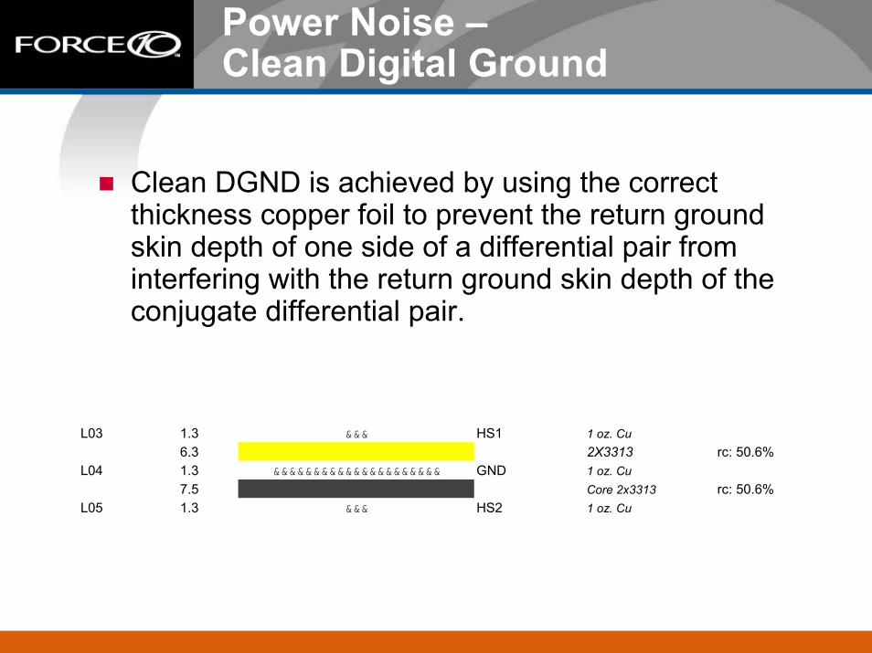
Power Noise –Clean Digital Ground
Clean DGND is achieved by using the correct thickness copper foil to prevent the return ground skin depth of one side of a differential pair from interfering with the return ground skin depth of the conjugate differential pair.
L03 1.3 &&& HS1 1 oz. Cu6.3 2X3313 rc: 50.6%
L04 1.3 &&&&&&&&&&&&&&&&&&&&& GND 1 oz. Cu7.5 Core 2x3313 rc: 50.6%
L05 1.3 &&& HS2 1 oz. Cu

Power Noise –Clean Chassis Ground
Employ edge guard bands.Cover top and bottom with cross hatch.Stitch top and bottom CGND layers with appropriate spaced thru-holes.Connect DGND and CGND with a single DC connection on the back plane. Connect DGND and CGND on line cards and switch fabrics with a DC-blocked connection. This concept is referred to as ‘Single Point Grounding’

Reflections –Worst Launch Conditions – Case 1
Poor Signal Integrity – SDD11/22/21Standard Cad ApproachEasiest / Lowest Cost to Implement
TP4 TP5Informative
13m
il D
rill
13m
il D
rill
13m
il D
rill
24mil
24mil
24milx32mil 24milx32mil 24mil
24mil
24mil
24mil
21mil BGA612milAG
trace to BP
trace trace
trace
trace dogbone
34mil Anti Pad

Reflections -Stub Effect and Low Zo S11SDD21 SDD11 SDD22 CH12 AGGR2 N4000-13
-75-70-65-60-55-50-45-40-35-30-25-20-15-10
-50
0 1000
2000
3000
4000
5000
6000
7000
8000
9000
10000
11000
12000
13000
14000
15000
Freq in MHZ
dB
SDD21XAUIForce10 SDD21

Loss -Channel Length 24inchesSDD21 SDD11 SDD22 CH7_7_10_7in N4000-13
-75-70-65-60-55-50-45-40-35-30-25-20-15-10
-50
0 1000
2000
3000
4000
5000
6000
7000
8000
9000
10000
11000
12000
13000
14000
15000
Freq in MHZ
dB
SDD21Force10 SDD21

Connector –Back Plane Requirements
9Ghz Band Width. Loss < 4dB.Pair Crosstalk within:– MDNEXT = 30-7.85*LOG(f/20000); f in MHz– MDFEXT = 35-11.27*LOG(f/20000); f in MHz– f = 50Mhz to 15000Mhz
No band width limiting bends in pair routing.Pad clearance supports 6mil, 7mil, or 8mil trace geometry.

Connector –Internal Routing

Connector –Floor Planning

Signaling / Coding Considerations
Channel Coding:– 8B10B– Scrambling
Signaling:– PAM4 or PAMx– NRZ

BER
The BER goal is 10E-15.– Simulate to 10E-17. – Tested in the lab for weeks at a time.– Current SERDES support 10E-13. Effective 10E-15 is
obtained by both power noise control and channel model integrity. The key is to set high standards on the analog rail voltage ripple by employing a power filter structure with excellent rejection.

Designing For EMI
Treat each slot as a unique chamber.– Use metal carriers to shield each slot..– Use honeycomb top and bottom.
Seal the back plane / mid plane.– Use high insertion loss gasketing.
Provide multiple connections at each mating surface.Bury all nets, using outer layers as pads only.Avoid return ground cross-over from plane to plane, preventing current from passing through decoupling caps. This allows the decoupling caps to be effective power filters.
Memory
Advanced CAMs– Less power per search– 4 times more performance– enhanced our flexible table management schemes
Memories– Replacing SRAMs with DRAMs when performance
allows– Quad Data Rate III SRAMs– Serdes based DRAMs for buffer memory
ASIC Technology
High Speed Interfaces– Interfaces to Macs, Backplane, Buffer Memory are all
SERDES based. SERDES all the way– SERDES to reduce pin count and gate count
Smaller Process Geometry– Definitely 0.09 micron or lower
– More gates(100% more gates over 0.13 micron process)
– Better performance(25% better performance)– Lower power(1/2 the 0.13 micron process power)– Use power optimized libraries
Hierarchical Placement and Layout of the Chips– Flat placement is no longer a viable option

Starting the 802.3 Call for Interest 100GbE
Gather interest from several companies. This is already in process.Determine market potential and required technology.Present to 802.3 January 2006.Requires 4 to 5 years.
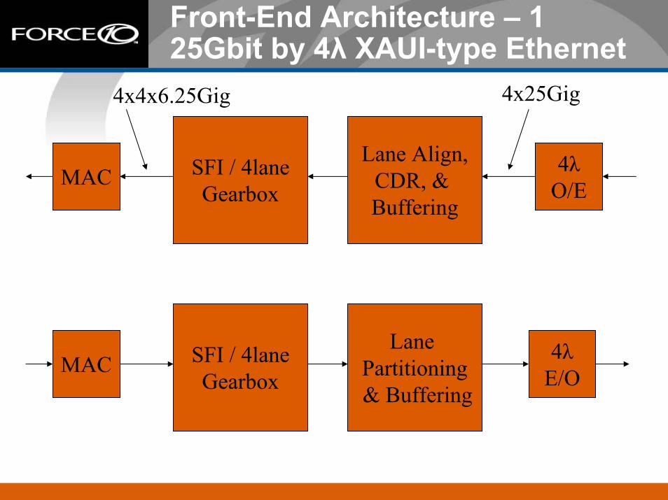
Front-End Architecture – 125Gbit by 4λ XAUI-type Ethernet
4x25Gig4x4x6.25Gig
Lane Align,CDR, & Buffering
4λO/E
SFI / 4laneGearbox
MAC
Lane Partitioning& Buffering
4λE/O
SFI / 4laneGearbox
MAC
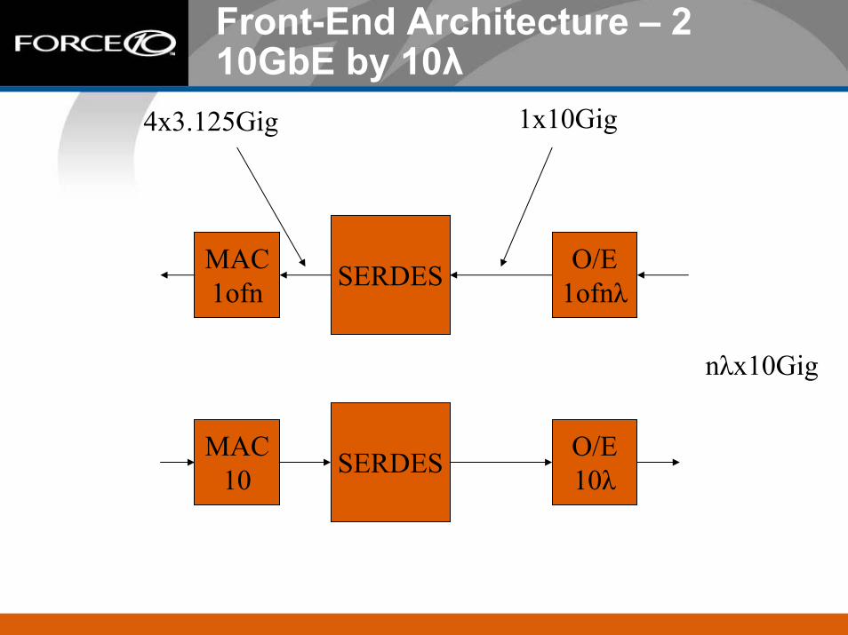
Front-End Architecture – 210GbE by 10λ
1x10Gig4x3.125Gig
MAC1ofn
O/E1ofnλSERDES
nλx10Gig
MAC10
O/E10λSERDES

Optical Parameters
SMF or MMF??– Likely SMF
Distance:– 40Km– 10Km– 300m– 50m electrical to be replaced by 50m/100m STP
Coding/signaling in process todayF10 to demonstrate basic blocks by year end.
Front-End Mechanical Concept
SFI-5p2 InterfaceMechanical form of 300pin MSA small form factor transponder module.Electrical connection yet to be defined.

Starting the 802.3 Call for Interest 25GbE Back Plane
Gather interest from several companies. This is already in process.Both market potential and technology are available today to support this.Present to 802.3 mid 2006.Requires 4 to 5 years.

25Gigabit Serdes
Requires OIF interface CEI/SFI-5 to run 6.25Gig4x6.25Gigabit parallel to 25Gigabit serial6.25Gig coding: NRZ or PAM-425Gig coding: Duo-BinaryChannel model available today

Summary
Design technology is the key to successful 100gig.25Gig back-end channels allow slot capacity to reach 500Gig.25Gig back-end channels match to 25Gigx4λ front-end connections.MAC breakdown into 6.25Gig lanes match to 25Gigx4λ front-end connections.Electrical and Optical components available today for experimentation.High Capacity slots are the stepping block to low cost / high density 10Gig Ethernet ports in excess of 1000 per system.


