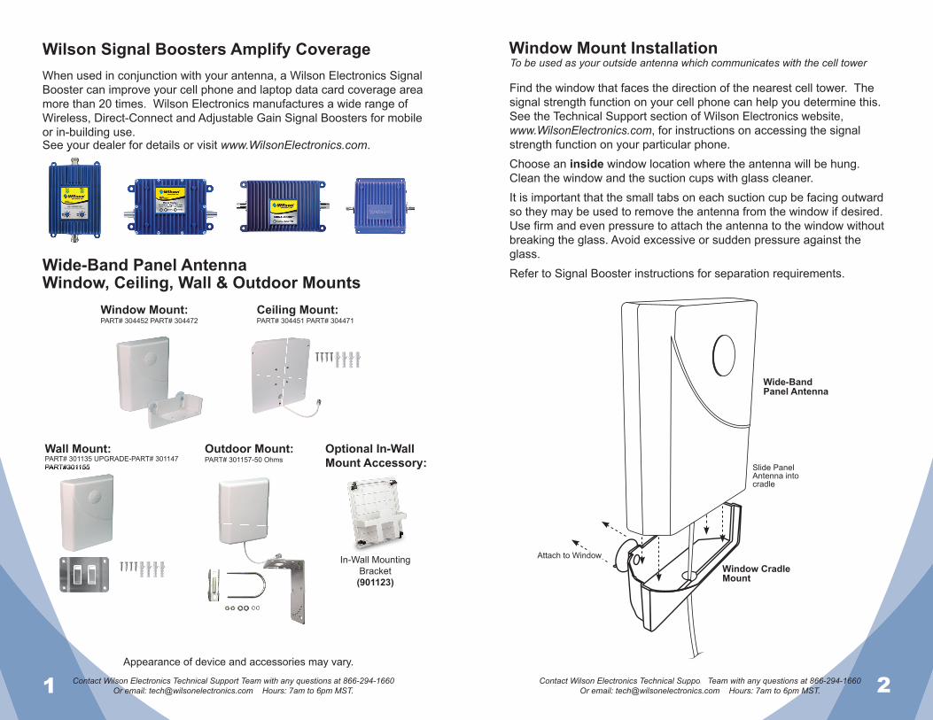
Wide-Band Panel Antenna Window, Ceiling, Wall & Outdoor Mounts Wilson ® Electronics, Inc. The wide-band panel antenna is vertically polarized. For optimum performance, install the antenna with the cable running from the bottom or the top. WINDOW PART# 304452-50 Ohms PART# 304472-75 Ohms CEILING PART# 304451-50 Ohms PART# 304471-75 Ohms WALL PART# 301135-50 Ohms UPGRADE-PART# 301147-50 Ohms PART#301155-75 Ohms OUTDOOR PART# 301157-50 Ohms Appearance of device and accessories may vary. Antenna
Transcript
Wide-BandPanel Antenna
Window, Ceiling, Wall& Outdoor Mounts
Wilson®
Electronics, Inc.
The wide-band panel antenna is vertically polarized. For optimum performance, install the antenna with the cable running from the
bottom or the top.
WINDOWPART# 304452-50 OhmsPART# 304472-75 Ohms
CEILINGPART# 304451-50 OhmsPART# 304471-75 Ohms
WALLPART# 301135-50 Ohms
UPGRADE-PART# 301147-50 OhmsPART#301155-75 Ohms
OUTDOORPART# 301157-50 Ohms
Appearance of device and accessories may vary.
Antenna
1 Contact Wilson Electronics Technical Support Team with any questions at 866-294-1660Or email: [email protected] Hours: 7am to 6pm MST. 2Contact Wilson Electronics Technical Support Team with any questions at 866-294-1660
Wilson Signal Boosters Amplify CoverageWhen used in conjunction with your antenna, a Wilson Electronics Signal Booster can improve your cell phone and laptop data card coverage area more than 20 times. Wilson Electronics manufactures a wide range of Wireless, Direct-Connect and Adjustable Gain Signal Boosters for mobile or in-building use.See your dealer for details or visit www.WilsonElectronics.com.See your dealer for details or visit
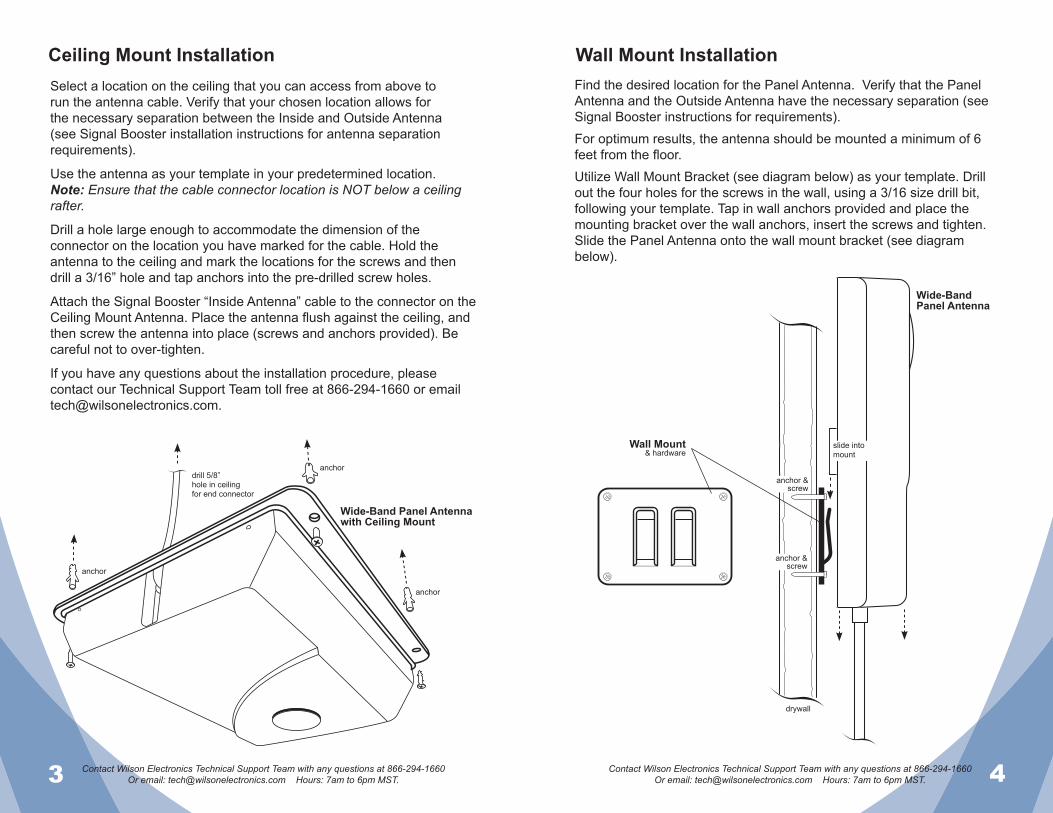
Find the window that faces the direction of the nearest cell tower. The signal strength function on your cell phone can help you determine this. See the Technical Support section of Wilson Electronics website,www.WilsonElectronics.com, for instructions on accessing the signal strength function on your particular phone.Choose an inside window location where the antenna will be hung. Clean the window and the suction cups with glass cleaner.It is important that the small tabs on each suction cup be facing outward so they may be used to remove the antenna from the window if desired. Use fi rm and even pressure to attach the antenna to the window without breaking the glass. Avoid excessive or sudden pressure against the glass.Refer to Signal Booster instructions for separation requirements.
To be used as your outside antenna which communicates with the cell tower
Wide-BandPanel Antenna
Window CradleMount
Attach to Window
Slide Panel Antenna intocradle
3 Contact Wilson Electronics Technical Support Team with any questions at 866-294-1660Or email: [email protected] Hours: 7am to 6pm MST. 4Contact Wilson Electronics Technical Support Team with any questions at 866-294-1660
Wall Mount InstallationCeiling Mount InstallationFind the desired location for the Panel Antenna. Verify that the Panel Antenna and the Outside Antenna have the necessary separation (see Signal Booster instructions for requirements).For optimum results, the antenna should be mounted a minimum of 6 feet from the fl oor.Utilize Wall Mount Bracket (see diagram below) as your template. Drill out the four holes for the screws in the wall, using a 3/16 size drill bit, following your template. Tap in wall anchors provided and place the mounting bracket over the wall anchors, insert the screws and tighten. Slide the Panel Antenna onto the wall mount bracket (see diagram below).
Wide-Band Panel Antennawith Ceiling Mount
anchor
slide into mount
drywall
anchoranchor &
screw
anchor &screw
drill 5/8”hole in ceilingfor end connector
anchor
Select a location on the ceiling that you can access from above to run the antenna cable. Verify that your chosen location allows for the necessary separation between the Inside and Outside Antenna (see Signal Booster installation instructions for antenna separation requirements).
Use the antenna as your template in your predetermined location.Note: Ensure that the cable connector location is NOT below a ceilingrafter.
Drill a hole large enough to accommodate the dimension of theconnector on the location you have marked for the cable. Hold theantenna to the ceiling and mark the locations for the screws and thendrill a 3/16” hole and tap anchors into the pre-drilled screw holes.
Attach the Signal Booster “Inside Antenna” cable to the connector on theCeiling Mount Antenna. Place the antenna fl ush against the ceiling, andthen screw the antenna into place (screws and anchors provided). Be careful not to over-tighten.
If you have any questions about the installation procedure, pleasecontact our Technical Support Team toll free at 866-294-1660 or [email protected].
Wide-BandPanel Antenna
Wall Mount& hardware
5 Contact Wilson Electronics Technical Support Team with any questions at 866-294-1660Or email: [email protected] Hours: 7am to 6pm MST. 6Contact Wilson Electronics Technical Support Team with any questions at 866-294-1660
Adjusting the Antenna for Maximum PerformanceTo adjust the antenna for best performance, connect it to your cell phone with an external adapter and a length of cable. External Antenna Adapters and cables are sold separately. Put the cell phone in test mode and turn the antenna in 10-degree increments while checking the cell phone’s signal level. At each point you may need to wait a few seconds as your cell phone updates. To fi nd your phone’s test mode, visit www.WilsonElectronics.com.
Once you have obtained the strongest signal, fully tighten the mounting hardware. After the Signal Booster and the rest of the system is installed and performing correctly, weatherproof all connections.Important: If you are using a wireless Signal Booster, be sure the antenna is not pointing across the building in which you are trying to get coverage. The antenna should point away from the building to help prevent oscillation (feedback).Ultra low loss cable is recommended for lengths 20’ or greater to prevent signifi cant signal loss. Wilson Electronics offers WILSON 400 cable in several lengths from 20-100 feet. Wilson Electronics also offers a wide range of phone adapters to connect your cell phone to a Signal Booster or directly to the antenna. To fi nd the adapter for your phone, visitwww.WilsonElectronics.com or call toll free 866-294-1660.
Signal readings usually appear as a negative number (for example, -86). The larger the number, the more powerful the signal (-75 is stronger than -84). See graph above.
The antenna should be mounted as shown in the illustration below. The included mounting bracket is adjustable and will accommodate pipe diameters from 1.25” to 2” (pipe sold separately part# 901117). Mount the antenna so that there is at least 3 feet of clearance in front and sides. Position the antenna so that it has the most unobstructed line of sight to the cellular service provider’s strongest signal. If you are using a wireless Signal Booster, make sure the antenna is not pointing across your own roof.Refer to Signal Booster instructions for separation requirements.Warning: Lightning protection is recommended for all installations, sold separately (Wilson Electronics Part #859902). Take extreme care to ensure that neither you nor the antenna comes near any electric power lines.
Outdoor Mount Installation
Wide-BandPanel Antenna
pipe sold separately part# 901117
Postion for strongest signal
Outdoor Mount& hardware
Part# 103074_Rev01_11.16.11
Wilson®
Electronics, Inc.
Antenna Specifi cations
Part Number 301134 301135 301147 304451 304452 301157 301155 304471 304472
Frequency Range 700-800 MHz / 824-894 MHz / 880-960 MHz / 1710-1880 MHz 1850-1900 MHz / 2110-2170 MHz
Dimension 8.27 x 7.09 x 1.73 (inch) / 21 x 18 x 4.39 (cm)
Weight 1.32 lbs / 0.6 kg
30-Day Money-Back Guarantee
All Wilson Electronics products are protected by Wilson Electronics 30-day money-back guarantee. If, for any reason, the performance of any product is not acceptable, simply return the product directly to the reseller with a dated proof of purchase.
90-Day Warranty
Wilson Electronics antennas are warranted for ninety (90) days against defects in workmanship and/or materials. Warranty cases may be resolved by returning the product directly to the reseller with a dated proof of purchase.
Antennas may also be returned directly to the manufacturer at the consumer’s expense, with a dated proof of purchase and a Returned Material Authorization (RMA) number supplied by Wilson Electronics. Wilson Electronics shall, at its option, either repair or replace the product. Wilson Electronics will pay for delivery of the repaired or replaced product back to the original consumer.
This warranty does not apply to any antennas determined by Wilson Electronics to have been subjected to misuse, abuse, neglect, or mishandling that alters or damages physical or electronic properties.
RMA numbers may be obtained by phoning Technical Support at 866-294-1660.
Disclaimer: The information provided by Wilson Electronics, Inc. is believed to be complete and accurate. However, no responsibility is assumed by Wilson Electronics, Inc. for any business or personal losses arising from its use, or for any infringements of patents or other rights of third parties that may result from its use.