236
www.empireflight.com ENEMY ENGAGED - RAH-66 COMANCHE VERSUS KA-52 HOKUM USER GUIDE USG-COHOKCDRUK

www.empireflight.com
ENEMY ENGAGED
- RAH-66 COMANCHE VERSUS KA-52 HOKUM
USER GUIDEUS
G-C
OH
OK
CD
RU
K
1036 MANUAL COVER UK 23/2/00 11:24 am Page 1

DISCLAIMERBy installing, copying, or otherwise using this Software product, you agree to be bound by
the limitations set out below.
LIMITED WARRANTYEmpire Interactive warrants that the software will perform substantially in accordance with
the accompanying written materials for a period of ninety (90) days from the date of
receipt. Any implied warranties on the software are limited to ninety (90) days, unless the
effect of this clause has been specifically excluded by applicable law.
CUSTOMER REMEDIESEmpire Interactive’s entire liability and your exclusive remedy shall be, at Empire Interactive’s
option, either (a) return of the price paid, or (b) replacement of the software or hardware
that does not meet this Limited Warranty and which is returned to the place of purchase
with a copy of your receipt. This Limited Warranty is void if failure of the software has
resulted from accident, abuse, or misapplication. Any replacement software will be
warranted for the remainder of the original warranty or thirty (30) days, whichever is longer.
NO OTHER WARRANTIESTo the maximum extent permitted by applicable law, Empire Interactive and its suppliers
disclaim all other representations, warranties, conditions or other terms, either express or
implied, including, but not limited to implied warranties and/or conditions of
merchantability and fitness for a particular purpose, with regard to the software and the
accompanying written materials.
NO LIABILITY FOR CONSEQUENTIAL DAMAGESTo the maximum extent permitted by applicable law, in no event shall Empire Interactive or
its suppliers be liable for any damages whatsoever (including without limitation, direct or
indirect damages for personal injury, loss of business profits, business interruption, loss of
business information, or any other pecuniary loss) arising out of the use of or inability to
use this product, even if Empire Interactive has been advised of the possibility of such
damages. In any case, Empire Interactive’s and its suppliers’ entire liability under any
provision of this agreement shall be limited to the amount actually paid by you for the
software, unless the effect of this clause has been specifically excluded by applicable law.
This Software Licence Agreement is governed by the law of the laws of England.
ENEMY ENGAGED - RAH-66 COMANCHE VERSUS KA-52 HOKUM AND EMPIRE ARE
TRADEMARKS OF ENTERTAINMENT INTERNATIONAL (UK) LTD. SOFTWARE ©2000 RAZORWORKS LTD. ALL
RIGHTS RESERVED. PUBLISHED BY EMPIRE INTERACTIVE. DOLBY AND THE DOUBLE D SYMBOL ARE
TRADEMARKS OF DOLBY LABORATORIES LICENSING CORPORATION.
1036 EE-CH Manual - Chap 1 23/3/00 12:31 pm Page 1

www.razorworks.com
1036 EE-CH Manual - Chap 1 23/3/00 12:31 pm Page 2

i
TECHNICAL SUPPORT
If you experience any technical problems with this or any other Empire product, please
contact our technical support staff.
When you call, it helps if you have the following information to hand: computer type,
available hard disk space, total RAM, type of video card and a list of the options you choose
when you installed the game. If possible be at your computer when you call.
TECHNICAL SUPPORT: (0)20 8343 9143 10am-6pm
If you prefer to write to us, be sure to enclose the same details.
Empire Interactive
Technical Support Dept.
The Spires, 677 High Road,
North Finchley
London N12 0DA
If you have internet access and would like to contact us on-line, you will find us at:
1036 EE-CH Manual - Chap 1 23/3/00 12:31 pm Page i

1. Introduction 1.0
Getting Started . . . . . . . . . . . . . . . . . . . . . . . . . . . . . . . . . . . . . . . . . . . . . . . . . . . . . . . . . . . . . . . . . . . . . . . 1.1
Quick Start . . . . . . . . . . . . . . . . . . . . . . . . . . . . . . . . . . . . . . . . . . . . . . . . . . . . . . . . . . . . . . . . . . . . . . . . . . . . 1.2
Strategy Guide . . . . . . . . . . . . . . . . . . . . . . . . . . . . . . . . . . . . . . . . . . . . . . . . . . . . . . . . . . . . . . . . . . . . . . . . 1.2
Updates . . . . . . . . . . . . . . . . . . . . . . . . . . . . . . . . . . . . . . . . . . . . . . . . . . . . . . . . . . . . . . . . . . . . . . . . . . . . . . . . 1.2
Compatibility With Apache Havoc . . . . . . . . . . . . . . . . . . . . . . . . . . . . . . . . . . . . . . . . . . . . . . . . . . . 1.3
Conversion Training From Apache Havoc . . . . . . . . . . . . . . . . . . . . . . . . . . . . . . . . . . . . . . . . . . . 1.3
2. Menu Screens 2.0
Main Screen . . . . . . . . . . . . . . . . . . . . . . . . . . . . . . . . . . . . . . . . . . . . . . . . . . . . . . . . . . . . . . . . . . . . . . . . . . . 2.1
Pilots Screen . . . . . . . . . . . . . . . . . . . . . . . . . . . . . . . . . . . . . . . . . . . . . . . . . . . . . . . . . . . . . . . . . . . . . . . . . . 2.1
Options Screen . . . . . . . . . . . . . . . . . . . . . . . . . . . . . . . . . . . . . . . . . . . . . . . . . . . . . . . . . . . . . . . . . . . . . . . 2.2
Combat Screen . . . . . . . . . . . . . . . . . . . . . . . . . . . . . . . . . . . . . . . . . . . . . . . . . . . . . . . . . . . . . . . . . . . . . . . 2.5
Session Screen . . . . . . . . . . . . . . . . . . . . . . . . . . . . . . . . . . . . . . . . . . . . . . . . . . . . . . . . . . . . . . . . . . . . . . . . 2.6
Gunship Screen . . . . . . . . . . . . . . . . . . . . . . . . . . . . . . . . . . . . . . . . . . . . . . . . . . . . . . . . . . . . . . . . . . . . . . . 2.6
Campaign and Mission Planning Screen . . . . . . . . . . . . . . . . . . . . . . . . . . . . . . . . . . . . . . . . . . . . . 2.7
3. In-Flight 3.0
Basic Handling . . . . . . . . . . . . . . . . . . . . . . . . . . . . . . . . . . . . . . . . . . . . . . . . . . . . . . . . . . . . . . . . . . . . . . . . 3.1
Missions . . . . . . . . . . . . . . . . . . . . . . . . . . . . . . . . . . . . . . . . . . . . . . . . . . . . . . . . . . . . . . . . . . . . . . . . . . . . . . . 3.5
Radio Messages . . . . . . . . . . . . . . . . . . . . . . . . . . . . . . . . . . . . . . . . . . . . . . . . . . . . . . . . . . . . . . . . . . . . . . . 3.8
Views . . . . . . . . . . . . . . . . . . . . . . . . . . . . . . . . . . . . . . . . . . . . . . . . . . . . . . . . . . . . . . . . . . . . . . . . . . . . . . . . . . 3.12
Controls . . . . . . . . . . . . . . . . . . . . . . . . . . . . . . . . . . . . . . . . . . . . . . . . . . . . . . . . . . . . . . . . . . . . . . . . . . . . . . . 3.18
4. Comanche Cockpits 4.0
Instrument Panel . . . . . . . . . . . . . . . . . . . . . . . . . . . . . . . . . . . . . . . . . . . . . . . . . . . . . . . . . . . . . . . . . . . . . . 4.2
Multi-Function Displays (MFDs) . . . . . . . . . . . . . . . . . . . . . . . . . . . . . . . . . . . . . . . . . . . . . . . . . . . . . 4.5
Helmet Integrated Display and Sight System (HIDSS) . . . . . . . . . . . . . . . . . . . . . . . . . . . . . 4.16
Acquiring Targets . . . . . . . . . . . . . . . . . . . . . . . . . . . . . . . . . . . . . . . . . . . . . . . . . . . . . . . . . . . . . . . . . . . . . . 4.19
Weapons . . . . . . . . . . . . . . . . . . . . . . . . . . . . . . . . . . . . . . . . . . . . . . . . . . . . . . . . . . . . . . . . . . . . . . . . . . . . . . . 4.30
Pilot Night Vision Sensor (PNVS) . . . . . . . . . . . . . . . . . . . . . . . . . . . . . . . . . . . . . . . . . . . . . . . . . . . . 4.39
Contents ii
1036 EE-CH Manual - Chap 1 23/3/00 12:31 pm Page ii

5. Hokum Cockpits 5.0
Instrument Panel . . . . . . . . . . . . . . . . . . . . . . . . . . . . . . . . . . . . . . . . . . . . . . . . . . . . . . . . . . . . . . . . . . . . . . 5.2
Multi-Function Displays (MFDs) . . . . . . . . . . . . . . . . . . . . . . . . . . . . . . . . . . . . . . . . . . . . . . . . . . . . . 5.6
Head Up Display (HUD) . . . . . . . . . . . . . . . . . . . . . . . . . . . . . . . . . . . . . . . . . . . . . . . . . . . . . . . . . . . . . . 5.15
Acquiring Targets . . . . . . . . . . . . . . . . . . . . . . . . . . . . . . . . . . . . . . . . . . . . . . . . . . . . . . . . . . . . . . . . . . . . . . 5.18
Weapons . . . . . . . . . . . . . . . . . . . . . . . . . . . . . . . . . . . . . . . . . . . . . . . . . . . . . . . . . . . . . . . . . . . . . . . . . . . . . . . 5.29
Night Vision Goggles (NVG) . . . . . . . . . . . . . . . . . . . . . . . . . . . . . . . . . . . . . . . . . . . . . . . . . . . . . . . . . 5.36
Windshield Wipers . . . . . . . . . . . . . . . . . . . . . . . . . . . . . . . . . . . . . . . . . . . . . . . . . . . . . . . . . . . . . . . . . . . . 5.37
Ejector Seats . . . . . . . . . . . . . . . . . . . . . . . . . . . . . . . . . . . . . . . . . . . . . . . . . . . . . . . . . . . . . . . . . . . . . . . . . . 5.37
6. Ground School 6.0
Helicopters – Basic Handling and Principles . . . . . . . . . . . . . . . . . . . . . . . . . . . . . . . . . . . . . . . . 6.1
Tactical Flying . . . . . . . . . . . . . . . . . . . . . . . . . . . . . . . . . . . . . . . . . . . . . . . . . . . . . . . . . . . . . . . . . . . . . . . . . 6.23
7. Comanche Versus Hokum 7.0
RAH-66 Comanche . . . . . . . . . . . . . . . . . . . . . . . . . . . . . . . . . . . . . . . . . . . . . . . . . . . . . . . . . . . . . . . . . . . 7.1
Ka-52 Hokum B "Alligator" . . . . . . . . . . . . . . . . . . . . . . . . . . . . . . . . . . . . . . . . . . . . . . . . . . . . . . . . . . . 7.7
8. Campaign Scenarios 8.0
Sword In The Sand . . . . . . . . . . . . . . . . . . . . . . . . . . . . . . . . . . . . . . . . . . . . . . . . . . . . . . . . . . . . . . . . . . . 8.2
War Of Independence . . . . . . . . . . . . . . . . . . . . . . . . . . . . . . . . . . . . . . . . . . . . . . . . . . . . . . . . . . . . . . . . 8.4
Task Force Lebanon . . . . . . . . . . . . . . . . . . . . . . . . . . . . . . . . . . . . . . . . . . . . . . . . . . . . . . . . . . . . . . . . . . . 8.6
9. Recognition Guide 9.0
10. Appendices 10.0
Trouble Shooting . . . . . . . . . . . . . . . . . . . . . . . . . . . . . . . . . . . . . . . . . . . . . . . . . . . . . . . . . . . . . . . . . . . . . . 10.1
Acronyms . . . . . . . . . . . . . . . . . . . . . . . . . . . . . . . . . . . . . . . . . . . . . . . . . . . . . . . . . . . . . . . . . . . . . . . . . . . . . . 10.7
Credits . . . . . . . . . . . . . . . . . . . . . . . . . . . . . . . . . . . . . . . . . . . . . . . . . . . . . . . . . . . . . . . . . . . . . . . . . . . . . . . . . 10.8
iii
1036 EE-CH Manual - Chap 1 23/3/00 12:32 pm Page iii

1. INTRODUCTION
1036 EE-CH Manual - Chap 1 23/3/00 12:32 pm Page iv

Enemy EngagedRAH-66 Comanche Versus Ka-52 Hokum
Throughout this manual the game title is abbreviated to ‘Comanche Hokum’.
Comanche Hokum is a combat flight simulator showcasing two state-of-the-art helicopters;
the American RAH-66 Comanche and the Russian Ka-52 Hokum B.
Both of these formidable gunships are capable of day, night and all weather missions and
able to operate away from base for extended periods at the front line.
Comanche Hokum provides an accurate simulation of both helicopters including realistic
flight dynamics, authentic weapons systems and detailed cockpits, displays and
instruments. You can fly as both pilot and co-pilot/gunner and the crew are fully animated
to increase the immersion.
There are options to configure the game for both novice and accomplished players. A ‘Quick
Start’ keyboard guide has also been included.
Comanche Hokum features three diverse, real world combat zones, accurately modelled
from digital data. The landscapes have rugged terrain ideally suited to low-level helicopter
combat and making ‘line of sight’ tactics a real part of the game play. Each campaign can
be played from either standpoint and in multiplayer games you can fly co-operatively or
competitively with other players.
The campaign ‘engine’ is fully dynamic and reactive. There are no scripted events or
outcomes. The war rages continuously, even when you are at a base re-arming and re-
fuelling. You fly realistic missions with your wingmen and can co-ordinate attacks via radio
messages. Your skill and judgement will determine success or failure.
Comanche Hokum features in excess of 60 different aircraft and vehicles all of which are
highly detailed and articulated and have realistic payloads and physics.
If you have Apache Havoc installed then Comanche Hokum will allow you to play the Apache
Havoc campaigns and to fly the Apache and Havoc gunships.
Getting Started
Installation
Insert your Comanche Hokum CD into your drive. If ‘Autorun’ is enabled on your system, the
Setup program will start automatically. If Autorun is not enabled, from Windows Explorer,
click on the autorun.exe icon on the Comanche Hokum CD.
Follow the on-screen instructions. Once all of the files have been copied on to your hard
drive, the installation process will create a shortcut for you.
Please note that a Direct3D compatible graphics accelerator card is required to run
Comanche Hokum.
INTRODUCTION1.1
1036 EE-CH Manual - Chap 1 23/3/00 12:32 pm Page 1.1

Starting
Comanche Hokum requires the full resources of your computer so terminate all other
running applications before starting.
The program requires the Comanche Hokum CD in your drive at all times during use.
To start the game, click on the Comanche Hokum shortcut created by the installation program.
If you experience any difficulty running Comanche Hokum then refer to the ‘Trouble
Shooting’ section in the Appendices.
Exiting
To exit Comanche Hokum return to the Main screen and click on the ‘EXIT’ button.
Alternatively, press l+X at any time.
Quick Start
To get in the air quickly then follow these steps:-
1. On the Main screen select ‘Combat’
2. On the Combat screen select ‘Free Flight’
3. On the Session screen select a scenario then ‘OK’
4. On the Gunship screen select a gunship then ‘SELECT’
You will be transferred to a base and placed in the cockpit of your gunship. You have infinite
weapons and fuel and are invulnerable to crashes. The enemy will not fire at you. These
options may be changed on the Session screen after selecting the scenario.
Refer to the ‘In-Flight’ chapter ‘Basic Handling’ section for the take-off and flight
procedures. Use the ‘Quick Start’ keyboard guide.
Press h to view the map. Press l+Q to quit.
Strategy Guide
On the Comanche Hokum CD is a Strategy Guide containing useful game play tactics and
much more. This is a HTML document and requires a web browser to read it.
Look in the ‘Strategy Guides\Comanche Hokum Guide’ folder.
Updates
Check www.razorworks.com for latest information and updates.
INTRODUCTION 1.2
1036 EE-CH Manual - Chap 1 23/3/00 12:32 pm Page 1.2

Compatibility With Apache Havoc
If you have Apache Havoc installed then Comanche Hokum will allow you to play the Apache
Havoc campaigns and to fly the Apache and Havoc gunships. Effectively giving Comanche
Hokum 6 combat zones and 4 different gunships to fly.
The installed version of Apache Havoc is not upgraded by Comanche Hokum and cannot
play the new campaigns.
For full compatibility you must upgrade the installed version of Apache Havoc to version
1.1E. The upgrade patches are supplied on the Comanche Hokum CD in the ‘Apache Havoc
Patches v1_1e’ folder. Simply launch the patch.exe within the language folder that matches
your version of Apache Havoc. Then run Apache Havoc once to apply the changes.
Conversion Training From Apache Havoc
If you are familiar with Apache Havoc then Comanche Hokum should be straight forward to
get used to. However, you should at least read chapter 2 ‘Menu Screens’ and chapter 3 ‘In-
Flight’ in this manual.
The Comanche Hokum keyboard layout is nearly identical to the Apache Havoc keyboard
layout. The ‘select object to view’ keys s to v have been changed. The cockpits are now
fully virtual and there are some key changes. The new keys are documented in the ‘In-Flight’
chapter.
If you fly the Apache or Havoc gunships from within Comanche Hokum, their cockpits are
the same as in Apache Havoc and only the pilot’s seat is modelled.
An incoming laser guided missile warning has been added to the Apache Aircraft
Survivability Equipment (ASE) MFD page and to the Havoc Threat Warning Display (TWD).
The Havoc TWD uses the right most lamp to indicate a laser guided missile warning. This
was previously documented as an early warning radar (EWR) lamp.
The new ‘altitude hold‘ function g+H does not apply to the Apache or Havoc gunships.
The Havoc ‘Toggle HUD size’ key has been changed from g+K to l+K
Comanche Hokum cannot read the Apache Havoc pilot logs.
INTRODUCTION1.3
1036 EE-CH Manual - Chap 1 23/3/00 12:32 pm Page 1.3
MENU SCREENS
2. MENU SCREENS
1036 EE-CH Manual - Chap 2 23/3/00 12:33 pm Page 1
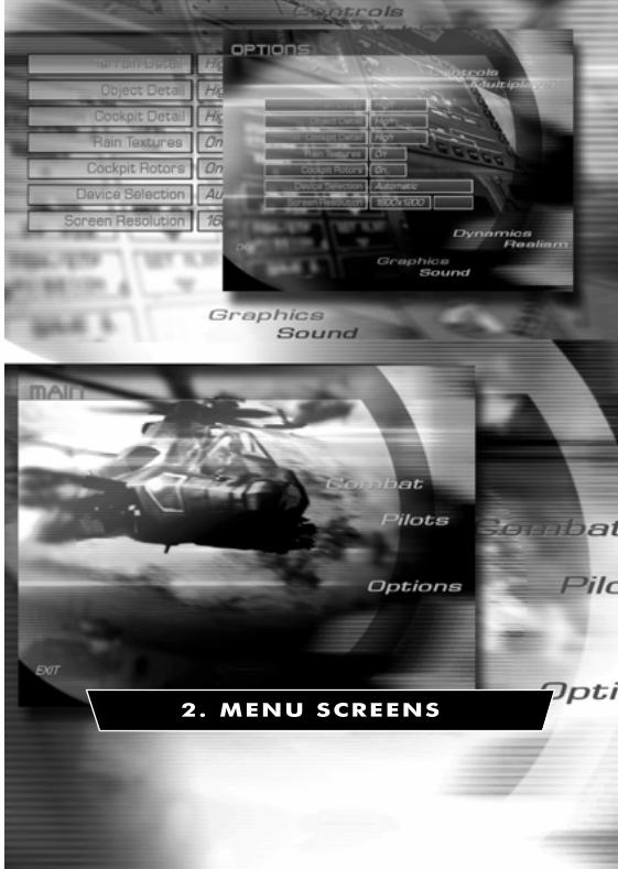
Use the mouse to make selections unless stated otherwise. You can click on ‘live’ text – that
is text which changes colour as you move the mouse over it.
Main Screen
Combat
Choose this option to advance to the Combat screen to select a game type.
Pilots
Choose this option to advance to the Pilots screen where you can select and create pilots
and view their logs and medals.
Options
Select this option to change the game settings.
EXIT
Exit the game.
Pilots Screen
Pilot Roster
The pilot roster allows you to Add, Rename and Delete pilots.
Select a pilot by clicking on his name.
Blue Force
Choose Blue Force to display the selected pilot’s logs and medals for flying the Comanche
(and Apache if Apache Havoc is installed).
Red Force
Choose Red Force to display the selected pilot’s logs and medals for flying the Hokum (and
Havoc if Apache Havoc is installed).
Medals
Choose Medals to view the selected pilot’s medals.
Weapons Log
Choose Weapons Log to view the selected pilot’s weapons log.
Flight Log
Choose Flight Log to view the selected pilot’s log.
MENU SCREENS2.1
1036 EE-CH Manual - Chap 2 23/3/00 12:33 pm Page 2.1

Rank
The selected pilot’s rank and date commissioned are displayed.
OK
Return to the Main screen.
Options Screen
Controls
Ensure that you have calibrated your game controllers before launching Comanche Hokum
(from the Start menu select Settings then Control Panel then Game Controllers).
Cyclic
Select Keyboard or Joystick for the cyclic stick.
Collective
Select Keyboard or Throttle for the collective lever.
Pedals
Select Keyboard or Rudder Pedals for the pedals.
Device
Cycle through the available game controllers to select the required device.
Reverse Throttle
A collective lever works in the reverse sense to a jet aircraft throttle. Setting this option to
on makes the collective work in the same sense as the throttle.
Multiplayer
To create (host) or join multiplayer games you will need to select a service provider
(connection method). Some service providers will require additional properties to be
entered.
You can join multiplayer games at any time as long as you have chosen an identical service
provider to the host.
When connecting to another player via a modem connection, the player who answers the
call is automatically assigned the host status. The host must wait in the Multiplayer screen
in order to connect to an incoming call.
Connection
Cycle through the connection options (Internet TCP/IP, Modem, Serial, IPX, etc.) to select
the required service provider and then enter the required parameters.
MENU SCREENS 2.2
1036 EE-CH Manual - Chap 2 23/3/00 12:33 pm Page 2.2

Dynamics
The options marked with an asterisk (*) are explained fully in chapter 6 ‘Ground School’.
*Blade Stall
Set retreating blade stall effect on or off. The imbalance of lift created by this effect will
cause the helicopter to roll and the pilot to apply constant cyclic corrections. Novice pilots
should turn this effect off.
Cross Couple
Set cross coupling effect on or off. With this option turned on the pilot will notice minimal
turning effect upon large collective inputs. Turning the cross coupling effect off will require
constant yaw input to maintain heading. Novice pilots should turn this effect on.
*Ground Effect
Set ground effect on or off. The ground effect simulates low altitude air cushioning created
by the rotor downwash. Novice pilots should turn this effect off.
Keyboard Assist
Set keyboard assistance on or off. Helicopter flight requires subtle inputs unobtainable from
keyboard control. Keyboard assistance implements a damping factor to help provide these
inputs and allow smoother flight.
Over-Torque
Set over-torque effect on or off. With over-torque set to off you will not get over-torque
warnings when the torque readout exceeds 100% and the gunship will not be damaged.
Novice pilots should turn this effect off.
*Vortex Ring
Set the vortex ring effect on or off. You can unintentionally create a vortex ring around your
main rotor if you make a sustained high-speed descent vertically or at a steep angle. This is
a hazardous situation! Novice pilots should turn this effect off.
Wind
Set wind effects on or off. Novice pilots should turn this effect off.
Realism
Co-Pilot Target ID
Sets the method in which target identifications are reported. Refer to ‘CP/G Assistance:
Target ID’ in the ‘Comanche Cockpit’ and ‘Hokum Cockpit’ chapters.
Co-Pilot ECM
Set Co-Pilot operating counter measures on or off. Set to on and the Co-Pilot will take care
of releasing chaff and flares and will operate the IR and Radar jammers. You can release
extra chaff and flares if required.
MENU SCREENS2.3
1036 EE-CH Manual - Chap 2 23/3/00 12:33 pm Page 2.3

Avionics
Select either Novice or realistic avionics. With Novice avionics selected you do not need to
operate the targeting devices. Arming a weapon will arm the HIDSS / HUD targeting modes
automatically and you can designate targets simply by looking at them. Refer to the
‘Comanche Cockpit’ and ‘Hokum Cockpit’ chapters.
Also, with Novice selected your wingmen are initially set to ‘Weapons Free’ so you do not
need to send a radio command to make them fire.
Difficulty
The difficulty option affects the enemy's response time and the amount of weapon damage
incurred. This only affects you and not the other entities in the world. In multiplayer games
each player retains their own difficulty level. That is, this value is not set globally by the
server. Therefore a novice player can compete with more experienced players by adjusting
their respective difficulty levels.
At the Easy difficulty setting, the player’s weapons do not take account of ‘armour penetration
angles’. Usually, if a weapon hits the front of a tank, where it is more heavily armoured, then
less damage will be inflicted than if the weapon hits the rear or sides of the tank.
Graphics
Terrain Detail
Select 3D terrain detail to suit your processor speed. High detail demands more processor
power than Low detail.
Object Detail
Select 3D object detail to suit your processor speed. High detail demands more processor
power than Low detail.
Cockpit Detail
Select cockpit detail to suit your processor speed. High detail demands more processor
power than Low detail.
Rain Textures
Cockpit rain textures may be set on or off as a matter of preference.
Cockpit Rotors
The main rotor blur effect visible from the cockpit may be set on or off as a matter of
preference.
Device Selection
Cycle through the available hardware graphics devices and select the hardware which has
the best Direct3D support. Changing device requires you to restart Comanche Hokum.
Screen Resolution
Cycle through the available screen resolutions and click ‘Accept’ to apply.
MENU SCREENS 2.4
1036 EE-CH Manual - Chap 2 23/3/00 12:33 pm Page 2.4

Sound
Sound Effects
Set sound effects on or off.
Music
Set music on or off.
Speech
Set all speech on or off.
Co-Pilot Speech
Set Co-Pilot speech on or off.
OK
Exit the Options screen.
Combat Screen
There are three different game types offered in the Combat screen plus a demo mode.
Campaign
Campaign games are large-scale dynamic campaigns based over the entire map. To win the
campaign you need to complete all of the given objectives.
Skirmish
Skirmish games are mini-campaigns contained within a small area of the map. Skirmish
games provide useful practice before taking on a full campaign and also require much less
bandwidth in multiplayer games.
Free Flight
Free Flight games allow you to explore all of the flying areas, practice flying and familiarise
yourself with the avionics and weapons systems.
Demo
The demo allows you to watch a campaign in action.
Press l+ Q or c to quit the demo.
CANCEL
Return to the Main screen.
MENU SCREENS2.5
1036 EE-CH Manual - Chap 2 23/3/00 12:33 pm Page 2.5

Session Screen
The session list shows all of the available games.
New games are listed in white text. If you have selected a multiplayer connection then
starting a new game makes you the host of that game.
Existing multiplayer games are listed in amber text. You may join these games at any time.
Saved games are listed in green text. Saved games may be renamed or deleted.
After you have selected a game, the game details and options are displayed.
Select ‘OK’ when you are ready to continue.
Select ‘CANCEL’ to return to the Combat screen.
Gunship Screen
From the Gunship screen select which side you want to play the campaign from.
Select ‘RAH-66 Comanche’ for the Blue Force and ‘KA-52 Hokum B’ for the Red Force.
If you have Apache Havoc installed then you can choose between flying Comanches and
Apaches or Hokums and Havocs in the campaign.
Select ‘SELECT’ to continue to the Campaign and Mission Planning screen.
Select ‘CANCEL’ to return to the Session screen.
MENU SCREENS 2.6
1036 EE-CH Manual - Chap 2 23/3/00 12:33 pm Page 2.6

Campaign and Mission Planning Screen
The Campaign and Mission Planning screen is the focal point of the campaign. From here
you get an overview of the campaign and can assess the current situation in order to decide
your next mission.
General Layout
MENU SCREENS2.7
SELECT INFORMATION
INFORMATION WINDOW
MESSAGE WINDOW
CURRENT MISSION STATUS
CURRENT GUNSHIP STATUSEXIT
SELECTMISSION
ANDGUNSHIP
CLEAR/QUIT MISSION
CAMPAIGNTIME
CONFIRM/COCKPIT
Familiarise yourself with the layout of this screen – try selecting all the options. You will
notice that many items react to a ‘mouse over’ event by displaying additional relevant
information as you move the mouse pointer over them. The additional information may
be displayed in the message window, on the map or in the current mission and gunship
status lines.
Generally you can click on graphical icons and ‘live’ text – that is text that changes colour
as you move the mouse pointer over it.
Diagram 2.1: General layout of the Campaign and Mission Planning screen
1036 EE-CH Manual - Chap 2 23/3/00 12:33 pm Page 2.7

Selecting a Mission and Gunship
There are several ways of selecting a mission and gunship and you can select them in any
order.
For instance, you may prefer to select a mission first simply because you want to fly a
particular type of mission. Alternatively you may opt to select a gunship first so that you
can fly with other players in a multiplayer game or you want to fly a particular type of
gunship if you have Apache Havoc installed.
‘Auto-Select’
The easiest way to select a mission and gunship is to use the auto-select function:-
1. Click the ‘Auto-Select’ text in the current mission status line and a mission will be
automatically selected. The mission briefing is displayed in the information window.
2. Click the ‘Auto-Select’ text in the current gunship status line and a gunship will be
automatically selected for the mission. The flight group details are displayed in the
information window.
3. Click ‘Confirm’ then ‘Cockpit’ to fly the mission.
‘Available’ and ‘OOB’ (Order Of Battle)
Select the ‘Available’ button to list all of the missions or groups available to you.
Select the ‘OOB’ button to list the ‘Order Of Battle’ for all of your forces (air, land and sea).
You can view missions, groups and bases.
‘Unassigned’ Missions
Unassigned mission are missions which have not been assigned to a flight group yet. If you
select an unassigned mission you then need to select a flight group in order to fly the
mission.
Unassigned missions may be taken by computer-controlled (AI) flight groups or by other
players in multiplayer games. Unassigned missions will eventually expire (timeout) if they are
not taken.
To select an unassigned mission and a gunship:-
1. Click ‘Clear’ / ’Quit Mission’ to clear any previously selected missions or gunships.
2. Select ‘Available’ and ‘Missions’.
3. Unassigned and assigned missions are listed, for example:-
Unassigned
[3 x RECON]
[2 x CAS]
Assigned
[1 x SEAD]
MENU SCREENS 2.8
1036 EE-CH Manual - Chap 2 23/3/00 12:33 pm Page 2.8

4. Click on a mission type to display the missions available, for example:-
Unassigned
[3 x RECON]
RECON #1
RECON #2
RECON #3
[2 x CAS]
Assigned
[1 x SEAD]
5. As you move the mouse pointer over the missions, details of the mission are shown in
the message window and the current mission status line. The mission is indicated on
the map (if it is view).
6. Click on a mission and a full briefing for the mission is displayed in the information
window.
7. Click ‘Accept’ to accept the mission. The ‘Groups’ button is automatically selected and
the flight groups available for this mission are listed. If no flight groups are available
then click ‘Clear Mission’ to start again.
8. Click on a flight group type to expand the groups available, for example:-
[2 x Recon / Attack Helicopters]
Freelancer
Gator
[1 x Attack Helicopters]
9. As you move the mouse pointer over the flight groups, details of the group are shown
in the message window and the current gunship status line. The flight group is indicated
on the map (if it is in view).
10. Click on a flight group and the group’s details are displayed in the information window.
11. You are normally assigned the flight group leaders gunship (i.e. ‘1-1 RAH-66 Comanche’)
but you can select another from the list.
12. Click ‘Accept’ to accept the gunship.
13. Click ‘Confirm’ then ‘Cockpit’ to fly the mission.
‘Assigned’ Missions
If you have accepted an assigned mission then the flight group is already selected but you
can change gunship within the group. Click ‘Accept’ to the gunship. Click ‘Confirm’ then
‘Cockpit’ to fly the mission.
MENU SCREENS2.9
1036 EE-CH Manual - Chap 2 23/3/00 12:33 pm Page 2.9
‘Completed’ Missions
Completed missions are only listed when the ‘OOB’ option is selected.
Map
There are many maps displayed in various contexts, however, the functionality of all maps
is the same.
Mouse Controls
The map reacts to ‘mouse over’ events. Simply point at icons to find out what they are.
Point to a location on the map and right-click to centre the map around this position.
Point to a location on the map and left-click to ‘goto’ (that is move your gunship to) this
position. This option is only available in Free Flight games.
Keyboard Controls
[ ] \ ^ Move map
= Zoom in
- Zoom out
+ (numpad) Zoom in
- (numpad) Zoom out
> Zoom in
< Zoom out
l+= Increase time acceleration (single player)
l+- Decrease time acceleration (single player)
l++ (numpad) Increase time acceleration (single player)
l+- (numpad) Decrease time acceleration (single player)
` Centre map on player
C Centre map on player
h Toggle cockpit/menus
Map Buttons
Maximise
Maximise map.
Minimise
Minimise map.
MENU SCREENS 2.10
1036 EE-CH Manual - Chap 2 23/3/00 12:33 pm Page 2.10

Zoom In
Zoom in.
Zoom Out
Zoom out.
Side
Toggle ‘side’ map.
The side map indicates the territorial possession of both sides.
Fog
Toggle ‘fog’ map.
The fog map indicates areas in which you have little or no intelligence.
Grid
Toggle the map grid.
Keysites
Toggle keysite icons. Keysites are tactical sites such as airbases,
FARPs, ports, oil refineries, etc.
Missions
Toggle mission destinations.
Air Forces
Toggle air force icons.
Ground Forces
Toggle ground force icons.
MENU SCREENS2.11
1036 EE-CH Manual - Chap 2 23/3/00 12:33 pm Page 2.11

Sea Forces
Toggle sea force icons.
Air Defences
Toggle air defence icons.
Ground Radar (threat circles)
Toggle air defence radar threat circles.
Track
Depending on the map context the track button does the following:-
1. Group information displayed – track the selected unit.
2. Mission information displayed – does nothing.
3. Base information displayed – does nothing.
4. All other maps – track the player’s gunship.
Goto
Toggle ‘goto’ feature. Only available in Free Flight games.
Map Icons
Move the mouse pointer over any map icon and details will be displayed in the message
window.
Event
The most recent event log message is displayed in the message window
and the event locator is displayed on the map to show the origin of the
message. Click on the message window to display the event log in the
information window.
MENU SCREENS 2.12
1036 EE-CH Manual - Chap 2 23/3/00 12:33 pm Page 2.12

Explosions
Explosions are drawn on the map indicating current engagements.
Waypoints
The waypoint route is displayed on the map.
Editing Waypoint Routes
The waypoint route can only be edited once the mission and gunship have been
confirmed (by clicking ‘Confirm’).
To move a waypoint, select it with the mouse pointer and drag it to a new location. The
start base, landing base and objective waypoints cannot be moved.
To insert a waypoint, click on the ‘+’ symbol between the two waypoints that you wish to
insert a new waypoint.
To delete a waypoint, highlight the waypoint by moving the mouse pointer over the
waypoint and press the ;key. The start base, landing base and objective waypoints
cannot be deleted.
Mission Briefing and Debriefing
The mission briefing is displayed in the information window. The details of the mission are
listed and a short account of the mission objectives is given.
After a mission is completed (successfully or unsuccessfully) the mission debriefing is
displayed in the information window.
To display your briefing or debriefing click the mission name (i.e. ‘RECON #2’) in the
current mission status line.
The mission briefing is available as soon as the mission is complete and not when you have
returned to base. At this point you can quit the mission (an AI pilot will fly the gunship back
to base) and you can select another mission to fly.
Promotion and Medals
After a mission you may be promoted or be awarded a medal. Details are given in the
debriefing.
Sit Rep (Situation Report)
The Sit Rep outlines your campaign objectives and gives an indication of the campaign
progress using ‘force strength’ and ‘kills/losses’ indicators.
In order to win the campaign your forces must successfully complete all of the campaign
objectives.
MENU SCREENS2.13
1036 EE-CH Manual - Chap 2 23/3/00 12:33 pm Page 2.13

Some objectives require your forces to capture an enemy installation. To achieve this your
forces must weaken the installation via strike missions. Once battle damage assessment has
shown the installation to be sufficiently weakened your forces will attempt to insert troops
to capture it.
Log (Event Log)
The event log keeps account of all the significant actions that have occurred during the
campaign.
The event log is listed with the latest event at the top. Click on any event text to view the
location of the message origin.
Payloads
After selecting a gunship you can change the weapon loadout. You can only change the
gunship’s weapons when you are landed at an airbase, carrier or FARP.
To change weapons cycle through the weapons available for each pylon or select a default
weapon loadout (air-to-ground, air-to-air or recon/scout).
You may change the weapon loadout for any of the gunships in your flight group. For
gunships other than Apache Longbows, Comanches, Havocs and Hokums you can only
select the three default options.
Chat
Use the chat facility to communicate with other players in multiplayer games.
Options
You can change the game options during a campaign, however, some options will be
unavailable and are greyed out.
Save
Save a campaign at any time. The saved game will be available on the Session screen.
Enter a filename for the saved game (restricted to 8 characters – there is no need to enter
a file extension).
Quit Campaign
To quit the campaign click the ‘Exit’ button or press l+ Q.
MENU SCREENS 2.14
1036 EE-CH Manual - Chap 2 23/3/00 12:33 pm Page 2.14

BASICS
3. IN-FLIGHT
1036 EE-CH Manual - Chap 3 23/3/00 12:37 pm Page 1

Basic Handling
If you are a novice pilot then it is recommended that you read the ‘Ground School’ section
of the manual to familiarise yourself with the basic principles and handling of a helicopter.
This section will guide you through the flight controls as required for Comanche Hokum
and explain the function of the automatic flight systems; ‘autopilot’, ‘altitude hold’ and
‘hover hold’.
Select a ‘Free Flight’ mission to practice your flight procedures. Ensure that you select a
passive environment and turn the collisions and weapon damage off.
The flight controls are the same for both Comanche and Hokum.
To re-iterate the lesson from Ground School:-
"It is worth emphasising that all your control movements ('controlinputs') should be as smooth and deliberate as possible. Sudden,violent control inputs are to be avoided whenever possible, butespecially in hovering or low-speed flight. Make sure that you knowwhere to find airspeed, altitude and vertical velocity readouts onthe Head-Up Display (HUD)."
Taking off and rising to the hover
1. Release the rotor brake R
2. The rotor blades will start to spin and the canopy doors will close
3. When the main rotor RPM has reached 90% the ‘RTR RPM’ warning light will turn off
and the helicopter is ready for take-off
4. Release the wheel brakes B
5. Watching the torque value on the head-up display, gently increase the collective to 65-
75% Q
6. The helicopter will start to climb
7. Climb to an altitude of 100 feet / 30 metres so that the helicopter is out of
‘ground effect’
8. Adjust the collective to hold the helicopter in a steady hover Q and A
Transition from the hover to forward flight
1. Ease the cyclic forward and the helicopter will start to accelerate \
2. The helicopter will lose altitude so gently increase the collective to compensate for
this Q
IN-FLIGHT3.1
1036 EE-CH Manual - Chap 3 23/3/00 12:37 pm Page 3.1

Climbing and diving
1. Pull back on the cyclic to climb ^
2. The helicopter will climb but lose forward speed
3. Push the cyclic forward to regain forward speed \
4. Raise the collective to climb Q
5. The helicopter will climb but gain forward speed
6. To climb without losing or gaining speed you need to simultaneously pull back on the
cyclic and raise the collective ^ and Q
7. Push the cyclic forward to dive \
8. The helicopter will lose height but gain forward speed
9. Pull the cyclic back to reduce the dive ^
10. Lower the collective to lose height A
11. The helicopter will lose height and forward speed
12. To dive without losing or gaining speed you need to simultaneously push forward on
the cyclic and lower the collective \ and A
Turning in forward flight
1. When the helicopter is hovering or flying at low speed (below 60 knots / 110 km/h) use
the pedals to turn Z and X
2. At higher speeds, turning is accomplished by tilting the cyclic left or right to bank the
helicopter ] and [
3. If you fly sustained or steeply-banked turns you’ll need to raise the collective Q or ease
back on the cyclic ^ (with loss of some forward speed) to avoid losing height
Slowing to the hover from forward flight
1. Start the manoeuvre by pulling back on the cyclic ^ to tilt the helicopter backwards
2. Lower the collective to prevent the helicopter from climbing A
3. As the helicopter slows, gently raise the collective Q to compensate for the diminished
main rotor thrust
4. As you approach the hover ease the cyclic forward \ to bring the helicopter level,
simultaneously raising the collective Q to maintain altitude
5. Use the pedals Z and X as necessary to keep the helicopter straight
IN-FLIGHT 3.2
1036 EE-CH Manual - Chap 3 23/3/00 12:37 pm Page 3.2

Landing1. From a steady hover, gently lower the collective A and the helicopter will begin to lose
altitude
2. Watching your vertical speed, adjust the collective Q and A to maintain a steady rate
of descent
3. Just before touchdown reduce the rate of descent to soften the landing
4. After touchdown, bottom the collective A
5. Engage the wheel brakes B
6. Engage the rotor brake R
7. The rotor blades will spin down and the canopy doors will open
Taxiing1. With the rotor blades spun up and the wheel brakes disengaged, increase the collective
Q to between 25 and 50%
2. To start taxiing, push gently forward on the cyclic \
3. Use the pedals Z and X to steer the helicopter
4. To slow down, ease back on the cyclic ^
5. To stop apply the wheel brakes B
Trim
Trim re-centres the cyclic to the currently held position. Trim is useful when flying long
distances in a straight line so that you do not need to keep pressure on the cyclic.
Autopilot
The autopilot system will fly the helicopter around the waypoint route and eventually land
back at base. Autopilot will not engage the enemy at ‘target’ waypoints.
G Autopilot (engage/disengage)
Autopilot is unavailable if the helicopter control systems are damaged or if the helicopter is
out of fuel.
Autopilot cannot be engaged when the helicopter's radar altitude is below 25 metres
(approximately 80 ft).
Coming in to land at a base, the helicopter may enter a holding pattern until a landing pad
becomes available.
IN-FLIGHT3.3
1036 EE-CH Manual - Chap 3 23/3/00 12:37 pm Page 3.3

Altitude Hold
The altitude hold system will attempt to hold the helicopter at the current radar altitude, in
effect, terrain following for nap of the earth flying.
Altitude hold is unavailable if the helicopter control systems are damaged or if the
helicopter is out of fuel.
The radar altitude setting can be increased or decreased by one unit at a time (1 foot
Comanche, 1 metre Hokum).
g+ H Altitude hold (engage/disengage)
g+ J Decrease altitude hold level
g+ K Increase altitude hold level
Hover Hold
The hover hold system will attempt to hold the helicopter in a stationary position
(station keeping).
Hover hold is unavailable if the helicopter control systems are damaged or if the helicopter
is out of fuel.
Hover hold can only be engaged if the horizontal velocity of the helicopter is below 20 knots
(approximately 40 Km/h).
Use collective to adjust the hover height and yaw to adjust the heading. Hover hold will
disengage with any cyclic input.
Hover hold bleeds off any horizontal velocity and adjusts the collective to zero the vertical
velocity. It is not an immediate effect and may take a few moments to stabilise. If you are
using a throttle stick then you will have to adjust the collective manually.
Stable hover hold is the same as hover hold except that it maintains altitude automatically
for players with throttle sticks.
H Hover hold (engage/disengage)
m+ H Stable hover hold (engage/disengage)
IN-FLIGHT 3.4
1036 EE-CH Manual - Chap 3 23/3/00 12:37 pm Page 3.4

Missions
Mission Types
The following airborne mission types are contained within Comanche Hokum.
Only missions marked with an asterisk (*) can be flown by the player. You will receive
confirmation of a successful mission completion or failure.
*Anti-ship Strike
Anti-ship strike missions are direct airborne assaults against enemy surface ships.
The mission is successfully completed when sufficient enemy ships have been destroyed.
BARCAP (BARCAP)
BARCAP missions are used to defend surface ships from attack. Fighter aircraft fly a circuit
(barrier) between the sea force and any potential threat.
*BDA (Battle Damage Assessment)
BDA missions are flown following a strike mission to assess the damage caused. Depending
on the information gained subsequent strike or troop insertion missions may be generated.
For successful mission completion the flight group leader must fly to within 500m of the
target waypoint and transmit recon data using the ‘Transmit Recon’ radio message.
*BAI (Battlefield Air Interdiction)
BAI missions are used to strike rear area reinforcements and supplies in order to destroy or
delay the enemy’s military potential before it can be used against friendly forces.
The mission is successfully completed when sufficient ground forces have been destroyed.
*CAP (Combat Air Patrol)
CAP missions are airborne patrols over a friendly area for the purpose of intercepting and
destroying enemy aircraft before they reach their target.
CAP missions last for a predetermined period of time. The mission is successfully
completed when this time has elapsed.
IN-FLIGHT3.5
1036 EE-CH Manual - Chap 3 23/3/00 12:37 pm Page 3.5
*CAS (Close Air Support)
CAS missions are airborne attacks against enemy forces which are in close proximity to
friendly forces.
The mission is successfully completed when sufficient enemy ground forces have been
destroyed.
*Escort
Armed escort missions provide protection for any vulnerable aircraft flying in a hostile area.
The mission is successfully completed when the escorted aircraft reach their destination.
*Ground Strike
Ground strike missions are direct airborne assaults against enemy ground installations.
The mission is successfully completed when sufficient enemy ground structures have been
destroyed.
OCA Strike (Offensive Counter Air Strike)
OCA strike missions are airborne attacks against landed air units at enemy airbases or
FARPs.
OCA Sweep (Offensive Counter Air Sweep)
OCA sweep missions are airborne attacks against enemy aircraft patrolling a target area.
*Recon (Reconnaissance)
A recon is mission is undertaken to obtain information about the activities and resources of
the enemy.
For successful mission completion the flight group leader must fly to within 500m of the
target waypoint and transmit recon data using the ‘Transmit Recon’ radio message.
Repair
Repair missions are used to deploy engineers and equipment at friendly ground installations
in order to repair damage caused by the enemy.
IN-FLIGHT 3.6
1036 EE-CH Manual - Chap 3 23/3/00 12:37 pm Page 3.6

*SEAD Strike (Suppression of Enemy Air Defences)
SEAD missions are used to destroy enemy air defences.
The mission is successfully completed when sufficient enemy air defence units have been
destroyed.
Supply
Supply missions are undertaken to deliver supplies to units and installations.
*Transfer
Transfer missions are used to move aircraft to where they are most needed.
The mission is successfully completed when the aircraft reach their destination.
Troop Insertion
Troop insertion missions are used to capture an enemy installation once the area has been
secured by a previous Strike or SEAD mission.
IN-FLIGHT3.7
1036 EE-CH Manual - Chap 3 23/3/00 12:37 pm Page 3.7

Radio Messages
You can send radio messages to your flight group, individual wingmen or the local base.
Radio messages marked with an asterisk (*) can only be transmitted by the flight group
leader.
@ Display radio message menu
0 to 9 Select menu option
c Exit menu (at any time)
l+@ Repeat radio message (the last message received)
m+A Attack my target
Any on-screen radio messages displayed in grey text are not available for some reason (i.e. you
need to be the flight group leader, the radio message applies to a certain mission type, etc.).
Flight Group and Wingman Commands
Attack My Target
Instructs the selected wingman (or the entire flight group) to attack your current target.
Your order will only be carried out if your target is not a friendly target and your
wingmen are capable of attacking it. This order cancels ‘Weapons Hold’.
If this instruction is sent to a human-controlled wingman, he will receive a text message
at the top of the screen showing the sender’s name and the target’s name, heading and
range. The heading and range are calculated from the recipient’s position.
Help Me
Instructs the selected wingman (or the entire flight group) to attack your current
pursuers. This order cancels ‘Weapons Hold’.
*Return To Base (flight group only)
Aborts all current missions. The whole flight group will return to base.
*Weapons Hold
Any flight group members in ‘Weapons Hold’ state will not fire at anything. ‘Weapons
Hold’ is cancelled by the orders ‘Weapons Free’, ‘Attack My Target’ and also if the flight
group member is fired at.
*Weapons Free
Cancels ‘Weapons Hold’ for the selected wingman or the entire flight group.
IN-FLIGHT 3.8
1036 EE-CH Manual - Chap 3 23/3/00 12:37 pm Page 3.8

*Hold Position
Using the ‘Hold Position’ command, wingmen can be instructed to remain in their
current position hovering at low altitude. The following conditions apply:-
1.This command cannot be issued to wingmen who are landing or landed.
2. If the wingman is taking off when the ‘Hold Position’ command is issued then he will
remember the position he was at when the command was given and return to wait at
that position once he has completed taking off.
3. If the wingman picks up a target, or is given a target by either ‘Attack My Target’ or ‘Help
Me’ commands, and is in ‘Weapons Free’ state, then he will continue attacking his targets
and return to his ordered hold position once all his targets are destroyed or a ‘Weapons
Hold’ command is issued.
The ‘Hold Position’ command will be cancelled by any of the following events:-
1. A ‘Rejoin Formation’ command is issued.
2. The flight leader reaches his final waypoint.
3. The flight leader is killed.
4. The player releases control of the flight leader (i.e. quits).
*Rejoin Formation
Cancels a ‘Hold Position’ command and allows the wingman to proceed as normal.
*Bob-Up
Used to co-ordinate ground attacks. If your wingman is in ‘Weapons Hold’ state, then
he will remain masked at his cover position until you give the order to ‘bob-up’. Upon
receiving this command he will increase altitude until he has sufficient line of sight to
the target, fire, and then re-mask. A wingman in ‘Weapons Free’ state will bob-up and
fire automatically. This option is only available to wingmen who are masked at their
cover positions and waiting for your command.
IN-FLIGHT3.9
1036 EE-CH Manual - Chap 3 23/3/00 12:37 pm Page 3.9

*Formation List (flight group only)
Select the new flight formation and the wingmen will re-position themselves.
IN-FLIGHT 3.10
Diagram 3.1: Flight group formations (‘1-1’ is the flight group leader)
Row Left Row Right
Echelon Left Echelon Right
Column Wedge
1-4 1-3 1-2 1-1
1-1
1-4
1 1-3
1-2
1-1 1-2 1-3 1-4
1-1
1-4
1-3
1-2
1-1
1-4
1-3 1-2
1-1
1-2
1-3
1-4
1036 EE-CH Manual - Chap 3 23/3/00 12:37 pm Page 3.10

Request Target List (other players only)
Only available if the selected wingman is human-controlled. The contents of the
selected wingman’s target list are added to your own target list.
Keyboard Message (other players only)
Only available if the selected wingman is human-controlled. Type in your own message
using the keyboard, press h when finished to send it, or press c at any time to
cancel.
LOCAL BASE
Request Airstrike
Creates a strike task depending on what you are targeting:-
1. Targeting an enemy structure will create a ground strike mission.
2. Targeting an enemy SAM or AAA will create a SEAD mission.
3. Targeting an enemy frontline ground unit will create a Close Air Support mission.
Request Artillery
Requests an artillery strike against the area surrounding your current target. The request
will be carried out if the target is valid and there is a friendly artillery unit within range.
Request Assistance
Scans the area for any friendly airborne units and instructs them to intercept your
current pursuers.
Transmit Recon
Only available when your current waypoint requires transmission of reconnaissance
data. If you are within 500m of your recon target then select this option to complete
the mission.
IN-FLIGHT3.11
1036 EE-CH Manual - Chap 3 23/3/00 12:37 pm Page 3.11

Views
Cockpit Views
In Comanche Hokum both pilot and co-pilot cockpits are included and you may assume
either crew role by switching seats. The cockpits are ‘virtual’ and may be panned as though
you are rotating the pilot’s head. There are also some close-up views of the displays.
The crew themselves are fully animated to increase the immersion of the game. There is a
special ‘Crew camera’ to observe them with.
c Switch pilot/co-pilot seat
g+ []\^ Pan view
o Forward view
p Instrument view
q Left MFD view, press again for instrument view
r Right MFD view, press again for instrument view
m+ p Hokum HUD view, press again for forward view
Alternative keys:-
m+ \ Pilot’s seat
m+ ^ Co-pilot’s seat
m+ ] Left MFD view, press again for instrument view
m+ [ Right MFD view, press again for instrument view
l+ \ Forward view
l+ ^ Instrument view
l+ ] Look left
l+ [ Look right
Cockpit Graphics
The cockpit graphics detail is selected using the Options Screen ‘Graphics’ menu. The
cockpit detail can also be changed in-flight:-
l+ r Increase cockpit detail
l+ q Decrease cockpit detail
You can fly without cockpit graphics but this leaves you with no points of reference and
it is easy to get disorientated. Alternatively there is a ‘glass’ cockpit option:-
l+ o Toggle cockpit graphics
l+ p Toggle glass cockpit
The blurred main rotor blades visible from the cockpit can be switched off in the
Options Screen 'Graphics' menu. The blurred main rotors can also be toggled in-flight:-
g+ R Toggle blurred main rotor blades
IN-FLIGHT 3.12
1036 EE-CH Manual - Chap 3 23/3/00 12:37 pm Page 3.12
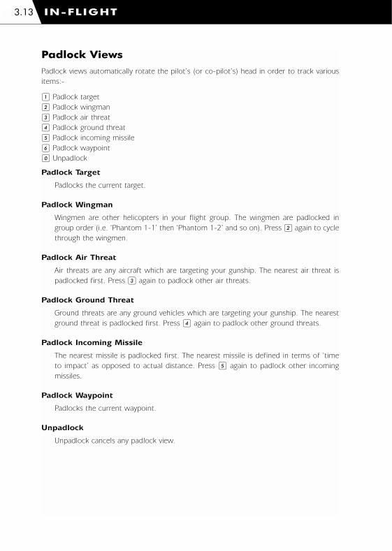
Padlock Views
Padlock views automatically rotate the pilot’s (or co-pilot’s) head in order to track various
items:-
1 Padlock target
2 Padlock wingman
3 Padlock air threat
4 Padlock ground threat
5 Padlock incoming missile
6 Padlock waypoint
0 Unpadlock
Padlock Target
Padlocks the current target.
Padlock Wingman
Wingmen are other helicopters in your flight group. The wingmen are padlocked in
group order (i.e. ‘Phantom 1-1’ then ‘Phantom 1-2’ and so on). Press 2 again to cycle
through the wingmen.
Padlock Air Threat
Air threats are any aircraft which are targeting your gunship. The nearest air threat is
padlocked first. Press 3 again to padlock other air threats.
Padlock Ground Threat
Ground threats are any ground vehicles which are targeting your gunship. The nearest
ground threat is padlocked first. Press 4 again to padlock other ground threats.
Padlock Incoming Missile
The nearest missile is padlocked first. The nearest missile is defined in terms of ‘time
to impact’ as opposed to actual distance. Press 5 again to padlock other incoming
missiles.
Padlock Waypoint
Padlocks the current waypoint.
Unpadlock
Unpadlock cancels any padlock view.
IN-FLIGHT3.13
1036 EE-CH Manual - Chap 3 23/3/00 12:37 pm Page 3.13

External Views
Selecting external views is split into two operations; selecting the object to view and
selecting the camera to view with. There is no given order in which these operations have
to occur.
Player’s Shortcuts
To quickly locate objects associated with the player:-
s Player’s gunship
t Player’s target
u Player’s weapon
v Player’s padlock
Player’s Gunship
Select the player’s gunship. External views of the player’s gunship show the head-up
display (HUD). This can be toggled on or off by pressing g+p
Player’s Target
Select the player’s target.
Player’s Weapon
Select the player’s weapon. Only viewable weapons can be selected – i.e. not cannon
shells – and if no weapon has been fired then the Weapon camera will be primed for
when a weapon is fired.
Player’s Padlock
Select the player’s padlock. This does not apply to waypoints.
Select Object To View
In Comanche Hokum there are many objects (aircraft, ground vehicles and ships)
involved in each campaign. In order to quickly locate any specific object use the ‘Select
Object To View’ menu simply referred to as the ‘Object’ menu.
z Toggle Object menu
View
Select the main group of objects to view:-
g+s View all
g+t View wingmen
g+u View players
g+v View available gunships
IN-FLIGHT 3.14
1036 EE-CH Manual - Chap 3 23/3/00 12:37 pm Page 3.14

View All
View all objects. Resets all Object menu options to ‘All’.
View Wingmen
View wingmen only.
View Players
View other player’s gunships only (in multiplayer games).
View Available Gunships
View available gunships only. In Comanche Hokum it is possible to change gunship in-
flight. Press g+ v to view available gunships only. Press l+ v to cycle the
available gunships. Press U to fly the gunship.
Range
View objects within a given range of the player’s gunship. If the player has not selected
a gunship then this option will be set to ‘All’.
g+ = Increase view range
g+ - Decrease view range
Alternatively (for Japanese keyboards):-
g+ +(Numpad) Increase view range
g+ -(Numpad) Decrease view range
Side
Select ‘side’ of objects to view.
l+ s next side
l+ s previous side
Category
Select ‘category’ of objects to view.
m+ u next category
m+ t previous category
Type
Select ‘type’ of objects within a category to view.
l+ u next type
l+ t previous type
IN-FLIGHT3.15
1036 EE-CH Manual - Chap 3 23/3/00 12:37 pm Page 3.15

Object
Select object to view. The number of objects available is shown in parenthesis.
l+ v next object
m+ v previous object
Short Object Menu
There is a shortened form of the Object menu displayed on the third line of the
‘External View Text’ (see below). This shows the current Object menu settings. When
you become accustomed to selecting an object to view you will probably no longer
require the full Object menu.
Select Camera
Any camera can be selected for any object:-
w Chase camera (pan and zoom)
m+ w Reset chase camera position behind object
g+ w Toggle lock/unlock chase camera to object
x Fly-by camera
m+ x Drop camera
l+ x Static camera (pan)
g+ x Weapon camera (only viewable weapons can be selected – i.e. not cannon
shells – and if no weapon has been fired then the Weapon camera will be primed for
when a weapon is fired)
y Auto-action camera (seeks out action within the limits of the Object menu settings
and uses a mix of cameras)
m+ y Cinematic camera (cinematic camera moves)
l+ y Crew camera (press again to cycle the camera positions for the selected crew
member)
g+ []^\ Pan view
g+ < Zoom out
g+ > Zoom in
External View Text
The external view text displayed at the bottom of the screen may be toggled on or off
by pressing l+ z.
Inset Target
If an object is tracking a target then an ‘inset’ view of the target can be displayed in the
top right corner of the screen.
g+ z Toggle inset target
IN-FLIGHT 3.16
1036 EE-CH Manual - Chap 3 23/3/00 12:37 pm Page 3.16
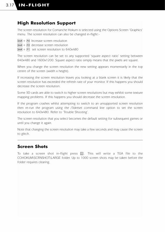
High Resolution Support
The screen resolution for Comanche Hokum is selected using the Options Screen ‘Graphics’
menu. The screen resolution can also be changed in-flight:-
m+ r Increase screen resolution
m+ q decrease screen resolution
m+ o set screen resolution to 640x480
The screen resolution can be set to any supported ‘square aspect ratio’ setting between
640x480 and 1600x1200. Square aspect ratio simply means that the pixels are square.
When you change the screen resolution the new setting appears momentarily in the top
centre of the screen (width x height).
If increasing the screen resolution leaves you looking at a blank screen it is likely that the
screen resolution has exceeded the refresh rate of your monitor. If this happens you should
decrease the screen resolution.
Some 3D cards are able to switch to higher screen resolutions but may exhibit some texture
mapping problems. If this happens you should decrease the screen resolution.
If the program crashes whilst attempting to switch to an unsupported screen resolution
then re-run the program using the /3dreset command line option to set the screen
resolution to 640x480. Refer to ‘Trouble Shooting’.
The screen resolution that you select becomes the default setting for subsequent games or
until you change it again.
Note that changing the screen resolution may take a few seconds and may cause the screen
to glitch.
Screen Shots
To take a screen shot in-flight press d. This will write a TGA file to the
COHOKUM\SCRNSHOT\LARGE folder. Up to 1000 screen shots may be taken before the
folder requires clearing.
IN-FLIGHT3.17
1036 EE-CH Manual - Chap 3 23/3/00 12:37 pm Page 3.17

Controls
Standard Joystick Configuration
Stick Cyclic
Hat switch (POV) Pan view
Button 1 Fire weapon
Button 2 Select weapon
Button 3 Select target
Button 4 Padlock/unpadlock target
Programmable Joystick Configurations
Programmable joystick configuration files are located in the 'Joystick' folder on the
Comanche Hokum CD.
‘Sticky’ Keys
Occasionally you may experience problems with 'sticky' keys.
For example, the torque value may continue to rise or fall even though you have released
the collective keys. Pressing and releasing the appropriate key will solve the problem
(press Q if the torque value is continuously rising, or press A if the torque value is
continuously falling).
Gamel+ X Exit game
l+ Q Quit mission/campaign
P Pause (single player)
l+ = Increase time acceleration (single player)
l+ - Decrease time acceleration (single player)
Alternatively (for Japanese keyboards):-
l+ +(Numpad) Increase time acceleration (single player)
l+ -(Numpad) Decrease time acceleration (single player)
h Toggle cockpits/menus
l+ I Toggle in-flight intelligence messages
l+ R Rearm, refuel and repair (cheat)
d Take screenshot
IN-FLIGHT 3.18
1036 EE-CH Manual - Chap 3 23/3/00 12:37 pm Page 3.18

Flight Controls
Cyclic, Collective, Tail Rotor
] Cyclic left
[ Cyclic right
\ Cyclic up
^ Cyclic down
Q or = Increase collective
A or - Decrease collective
Z Tail rotor left
X Tail rotor right
T Trim cyclic
m+ T Clear trim
Autopilot
G Autopilot (engage/disengage)
g+ H Altitude hold (engage/disengage)
g+ J Decrease altitude hold level
g+ K Increase altitude hold level
H Hover hold (engage/disengage)
m+ H Stable hover hold (engage/disengage)
Miscellaneous
R Rotor brake (engage/disengage)
B Wheel brake (engage/disengage)
l+ G Gear (raise/lower)
g+ E Eject (Hokum)
Cockpit
Warnings
M Acknowledge master caution
l+ F Fire extinguishers (once per mission)
IN-FLIGHT3.19
1036 EE-CH Manual - Chap 3 23/3/00 12:37 pm Page 3.19

Radio Messages
@ Display radio message
l+ @ Repeat radio message
m+ A Attack my target
Navigation
W Select next waypoint (flight group leader)
m+ W Select previous waypoint (flight group leader)
Night Flying
N Night vision (on/off) – PNVS (Comanche) / NVG (Hokum)
V Navigation lights (on/off)
Wipers
Y Wipers (on/off) (Hokum)
g+ Y Toggle intermittent wipe (Hokum)
HIDSS (Comanche) / HUD (Hokum)
K Select next HIDSS (Comanche) / HUD (Hokum) colour
m+ K Select previous HIDSS (Comanche) / HUD (Hokum) colour
O Engage bob-up
l+ O Disengage bob-up
Multi-Function Displays (MFDs)
E Increase TSD and ASE/TWD range
m+ E Decrease TSD and ASE/TWD range
D Select next TSD declutter level
m+ D Select previous TSD declutter level
l+ A Toggle ASE/TWD auto-page
Cycle MFD Pages
( Select next left MFD page
m+ ( Select previous left MFD page
l+ ( Left MFD on/off
) Select next right MFD page
m+ ) Select previous right MFD page
l+ ) Right MFD on/off
g+ ( Left side display on/off (Comanche)
g+ ) Right side display on/off (Comanche)
IN-FLIGHT 3.20
1036 EE-CH Manual - Chap 3 23/3/00 12:37 pm Page 3.20
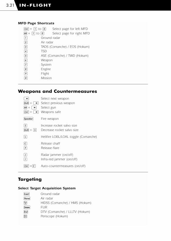
MFD Page Shortcuts
l+ 1 to 0 Select page for left MFD
g+ 1 to 0 Select page for right MFD
1 Ground radar
2 Air radar
3 TADS (Comanche) / EOS (Hokum)
4 TSD
5 ASE (Comanche) / TWD (Hokum)
6 Weapon
7 System
8 Engine
9 Flight
0 Mission
Weapons and Countermeasures
i Select next weapon
m+ i Select previous weapon
g+ i Select gun
l+ i Weapons safe
n Fire weapon
S Increase rocket salvo size
m+ S Decrease rocket salvo size
L Hellfire LOBL/LOAL toggle (Comanche)
C Release chaff
F Release flare
J Radar jammer (on/off)
I Infra-red jammer (on/off)
l+C Auto-countermeasures (on/off)
Targeting
Select Target Acquisition System
k Ground radar
` Air radar
_ HIDSS (Comanche) / HMS (Hokum)
; FLIR
f DTV (Comanche) / LLLTV (Hokum)
e Periscope (Hokum)
IN-FLIGHT3.21
1036 EE-CH Manual - Chap 3 23/3/00 12:37 pm Page 3.21

Alternatively (for programmable joysticks):-
m+ 1 Ground radar
m+ 2 Air radar
m+ 3 HIDSS (Comanche) / HMS (Hokum)
m+ 4 FLIR
m+ 5 DTV (Comanche) / LLLTV (Hokum)
m+ 6 Periscope (Hokum)
Radar Controls (use numeric keypad)
4 Scan left
5 Scan centre
6 Scan right
8 Increase scan size
2 Decrease scan size
+ Increase range
- Decrease range
9 Increase target priority (ground radar)
3 Decrease target priority (ground radar)
1 Engage auto-target
7 Toggle allied aircraft / all aircraft (air radar)
* Toggle single / continuous sweep
/ Activate single radar sweep
j Lock/unlock target
l+ j Padlock/unpadlock target
0 Select next target
m+ 0 Select previous target
l+ ; Switch radar off
TADS (Comanche) / EOS (Hokum) Controls (use numeric keypad)
4 Pan left
5 Pan centre
6 Pan right
8 Pan up
2 Pan down
+ Increase zoom
- Decrease zoom
j Lock/unlock target
l+ j Padlock/unpadlock target
0 Select next target
m+ 0 Select previous target
l+ ; Switch TADS / EOS off
IN-FLIGHT 3.22
1036 EE-CH Manual - Chap 3 23/3/00 12:37 pm Page 3.22
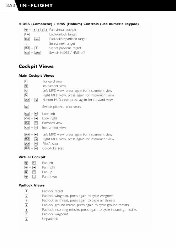
HIDSS (Comanche) / HMS (Hokum) Controls (use numeric keypad)
g+ 4682 Pan virtual cockpit
j Lock/unlock target
l+ j Padlock/unpadlock target
0 Select next target
m+ 0 Select previous target
l+ ; Switch HIDSS / HMS off
Cockpit Views
Main Cockpit Views
o Forward view
p Instrument view
q Left MFD view, press again for instrument view
r Right MFD view, press again for instrument view
m+ p Hokum HUD view, press again for forward view
c Switch pilot/co-pilot seats
l+ ] Look left
l+ [ Look right
l+ \ Forward view
l+ ^ Instrument view
m+ ] Left MFD view, press again for instrument view
m+ [ Right MFD view, press again for instrument view
m+ \ Pilot’s seat
m+ ^ Co-pilot’s seat
Virtual Cockpit
g+ ] Pan left
g+ [ Pan right
g+ \ Pan up
g+ ^ Pan down
Padlock Views
1 Padlock target
2 Padlock wingman, press again to cycle wingmen
3 Padlock air threat, press again to cycle air threats
4 Padlock ground threat, press again to cycle ground threats
5 Padlock incoming missile, press again to cycle incoming missiles
6 Padlock waypoint
0 Unpadlock
IN-FLIGHT3.23
1036 EE-CH Manual - Chap 3 23/3/00 12:37 pm Page 3.23
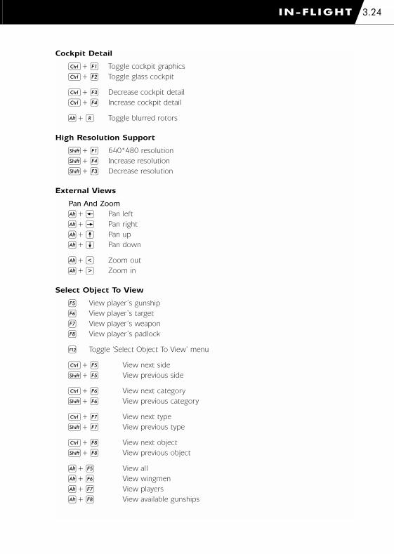
Cockpit Detail
l+ o Toggle cockpit graphics
l+ p Toggle glass cockpit
l+ q Decrease cockpit detail
l+ r Increase cockpit detail
g+ R Toggle blurred rotors
High Resolution Support
m+ o 640*480 resolution
m+ r Increase resolution
m+ q Decrease resolution
External Views
Pan And Zoom
g+ ] Pan left
g+ [ Pan right
g+ \ Pan up
g+ ^ Pan down
g+ < Zoom out
g+ > Zoom in
Select Object To View
s View player’s gunship
t View player’s target
u View player’s weapon
v View player’s padlock
z Toggle ‘Select Object To View’ menu
l+ s View next side
m+ s View previous side
l+ t View next category
m+ t View previous category
l+ u View next type
m+ u View previous type
l+ v View next object
m+ v View previous object
g+ s View all
g+ t View wingmen
g+ u View players
g+ v View available gunships
IN-FLIGHT 3.24
1036 EE-CH Manual - Chap 3 23/3/00 12:37 pm Page 3.24

g+ = Increase view range
g+ - Decrease view range
Alternatively (for Japanese keyboards):-
g+ +(Numpad) Increase view range
g+ -(Numpad) Decrease view range
Select Camera
w Chase camera
m+ w Reset chase camera position
g+ w Lock/unlock chase camera
x Fly-by camera
m+ x Drop camera
l+ x Static camera
g+ x Weapon camera
y Auto-action camera
m+ y Cinematic camera
l+ y Crew camera
Miscellaneous
g+p Toggle external view HIDSS (Comanche) / HUD (Hokum)
l+z Toggle external view object text
g+z Toggle external view inset target
U Fly external view gunship (available gunship only)
IN-FLIGHT3.25
1036 EE-CH Manual - Chap 3 23/3/00 12:37 pm Page 3.25

4. COMANCHE COCKPITS
1036 EE-CH Manual - Chap 4 23/3/00 12:38 pm Page 1

COMANCHE COCKPITS4.1
Diagram 4.1: Pilot’s cockpit (front seat)
Diagram 4.2: Stepped cockpit configuration (pilot at the front)
1036 EE-CH Manual - Chap 4 23/3/00 12:38 pm Page 4.1

COMANCHE COCKPITS 4.2
Instrument Panel
The Comanche has two identical cockpits in a stepped configuration. The pilot sits in the
front seat and the co-pilot (CP/G) sits in the rear seat. You can assume either of the crew
roles.
Each cockpit has two ‘main’ multi-function displays (MFDs) and two ‘side’ displays. There
are some indicator lights but there are no traditional instruments for backup.
Refer to the In-flight ‘Views’ section for details of the cockpit views.
Master Caution Light
The master caution light flashes, accompanied by an audible warning, to indicate that there
is a problem. The problem will be indicated by the warning lights or Upfront Display. To
acknowledge the caution press M. This extinguishes the master caution light and silences
the audible warning.
Engine Ignition Lights
L ENG Left engine ignition
APU APU ignition
R ENG Right engine ignition
1036 EE-CH Manual - Chap 4 23/3/00 12:38 pm Page 4.2

Fire Warning Lights
The fire warning lights indicate if either engine or the auxiliary power unit (APU) is on fire.
In case of a fire use the fire extinguisher. The fire extinguisher can only be used once per
mission.
L ENG Left engine ignition
APU APU ignition
R ENG Right engine ignition
l+ F Activate fire extinguisher
Fire Extinguisher Lights
The fire extinguisher lights indicate if the fire extinguishers have been used.
Warning Lights
TRQ Engine over torque
RTR RPM Low main rotor RPM
FUEL LOW Low fuel level (<25% maximum fuel level)
HYD PRESS Low hydraulic pressure
OIL PRESS Low or high engine oil pressure
OIL TEMP High engine oil temperature
COMANCHE COCKPITS4.3
1036 EE-CH Manual - Chap 4 23/3/00 12:39 pm Page 4.3
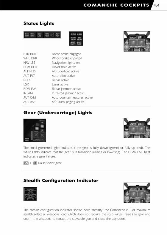
Status Lights
RTR BRK Rotor brake engaged
WHL BRK Wheel brake engaged
NAV LTS Navigation lights on
HOV HLD Hover-hold active
ALT HLD Altitude-hold active
AUT PLT Auto-pilot active
RDR Radar active
LSR Laser active
RDR JAM Radar jammer active
IR JAM Infra-red jammer active
AUT C/M Auto-countermeasures active
AUT ASE ASE auto-paging active
Gear (Undercarriage) Lights
The small green/red lights indicate if the gear is fully down (green) or fully up (red). The
white lights indicate that the gear is in transition (raising or lowering). The GEAR FAIL light
indicates a gear failure.
l+ G Raise/lower gear
Stealth Configuration Indicator
The stealth configuration indicator shows how ‘stealthy’ the Comanche is. For maximum
stealth select a weapons load which does not require the stub wings, raise the gear and
unarm the weapons to retract the stowable gun and close the bay doors.
COMANCHE COCKPITS 4.4
1036 EE-CH Manual - Chap 4 23/3/00 12:39 pm Page 4.4

Upfront Display
The upfront display shows system messages.
Multi-Function Displays (MFDs)Each cockpit has two ‘main’ multi-function displays (MFDs) and two ‘side’ displays.
Each main MFD can display one of ten selectable pages:-
Ground Radar
Air Radar
Target Acquisition and Designation Sight (TADS)
Tactical Situation Display (TSD)
Aircraft Survivability Equipment (ASE)
Weapon*
System*
Engine*
Flight*
Mission
The side display pages are fixed and duplicate the main MFD pages indicated by the * above.
The pages can be cycled through on each main MFD:-
( Select next left main MFD page
m+ ( Select previous left main MFD page
) Select next right main MFD page
m+ ) Select previous right main MFD page
The displays can be switched on and off:-
l+ ) Switch left main MFD on and off
l+ ) Switch right main MFD on and off
g+ ) Switch left side display on and off
g+ ) Switch right side display on and off
COMANCHE COCKPITS4.5
1036 EE-CH Manual - Chap 4 23/3/00 12:39 pm Page 4.5

There are shortcut keys to select any page on either MFD.
Left MFD:-
l+ 1 Ground Radar
l+ 2 Air Radar
l+ 3 Target Acquisition and Designation Sight (TADS)
l+ 5 Aircraft Survivability Equipment (ASE)
l+ 6 Weapon
l+ 7 System
l+ 8 Engine
l+ 9 Flight
l+ 0 Mission
Right MFD:-
g+ 1 Ground Radar
g+ 2 Air Radar
g+ 3 Target Acquisition and Designation Sight (TADS)
g+ 5 Aircraft Survivability Equipment (ASE)
g+ 6 Weapon
g+ 7 System
g+ 8 Engine
g+ 9 Flight
g+ 0 Mission
Ground Radar MFD
See the 'Acquiring Targets' section.
Air Radar MFD
See the 'Acquiring Targets' section.
Target Acquisition and Designation System (TADS)MFD
See the 'Acquiring Targets' section.
COMANCHE COCKPITS 4.6
1036 EE-CH Manual - Chap 4 23/3/00 12:39 pm Page 4.6

Tactical Situation Display (TSD) MFD
The Tactical Situation Display shows navigation information, targets, anti-aircraft threats and
air threats and is essential during combat situations.
Helicopter Datum
The TSD shows a plan view of the battlefield with the helicopter located at the bottom
of the display.
Declutter Level
The TSD has 3 declutter levels:-
ALL Display both target and navigation information
TGT Display target information only
NAV Display navigation information only
D Next TSD declutter level
m+ D Previous TSD declutter level
TSD Range
The TSD range is selectable between 2, 5, 10 and 25Km. This also changes the range
of the ASE display.
E Next TSD range
m+ E Previous TSD range
COMANCHE COCKPITS4.7
Sensor type
Radar scan
limits
Helicopter datum
Targets/threats Selected target
range
TSD range
Declutter level
(target)
Threat range
circles
Selected target
Threat is targeting
helicopter
(flashes when a missile
is launched)
Diagram 4.3: TSD MFD (target declutter)
1036 EE-CH Manual - Chap 4 23/3/00 12:39 pm Page 4.7
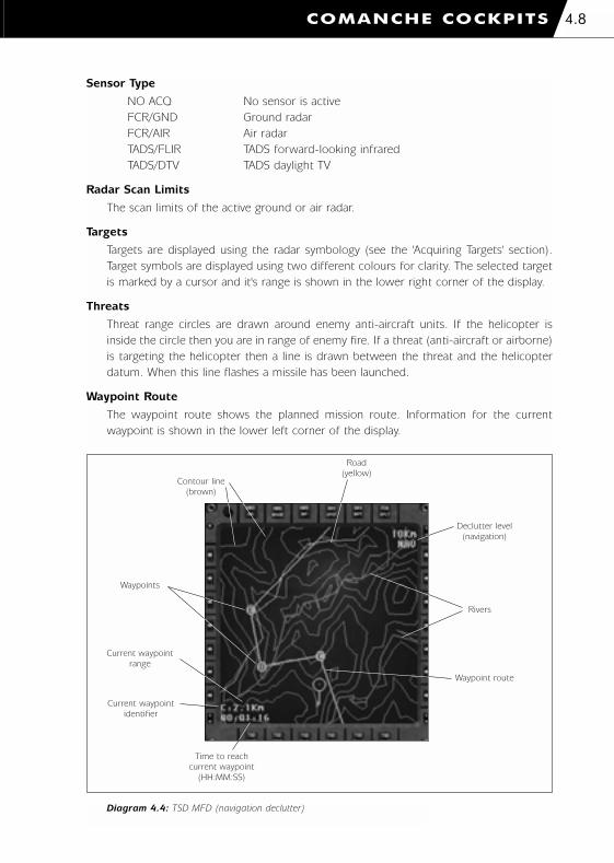
COMANCHE COCKPITS 4.8
Diagram 5.3: TSD MFD (navigation declutter)
Sensor Type
NO ACQ No sensor is active
FCR/GND Ground radar
FCR/AIR Air radar
TADS/FLIR TADS forward-looking infrared
TADS/DTV TADS daylight TV
Radar Scan Limits
The scan limits of the active ground or air radar.
Targets
Targets are displayed using the radar symbology (see the 'Acquiring Targets' section).
Target symbols are displayed using two different colours for clarity. The selected target
is marked by a cursor and it's range is shown in the lower right corner of the display.
Threats
Threat range circles are drawn around enemy anti-aircraft units. If the helicopter is
inside the circle then you are in range of enemy fire. If a threat (anti-aircraft or airborne)
is targeting the helicopter then a line is drawn between the threat and the helicopter
datum. When this line flashes a missile has been launched.
Waypoint Route
The waypoint route shows the planned mission route. Information for the current
waypoint is shown in the lower left corner of the display.
Current waypoint
range
Current waypoint
identifier
Time to reach
current waypoint
(HH:MM:SS)
Declutter level
(navigation)
Rivers
Waypoint route
Road
(yellow)
Waypoints
Contour line
(brown)
Diagram 4.4: TSD MFD (navigation declutter)
1036 EE-CH Manual - Chap 4 23/3/00 12:39 pm Page 4.8
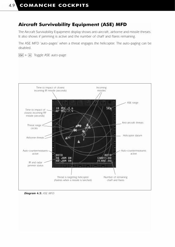
Aircraft Survivability Equipment (ASE) MFD
The Aircraft Survivability Equipment display shows anti-aircraft, airborne and missile threats.
It also shows if jamming is active and the number of chaff and flares remaining.
The ASE MFD ‘auto-pages’ when a threat engages the helicopter. The auto-paging can be
disabled.
l+ A Toggle ASE auto-page
COMANCHE COCKPITS4.9
Time to impact of closest
incoming IR missile (seconds)
Threat range
circles
Incoming
missiles
Diagram 4.5: ASE MFD
ASE range
Helicopter datum
Anti-aircraft threats
Auto-countermeasures
active
Threat is targeting helicopter
(flashes when a missile is lanched)
Number of remaining
chaff and flares
IR and radar
jammer status
Auto-countermeasures
active
Airborne threats
Time to impact of
closest incoming RF
missile (seconds)
1036 EE-CH Manual - Chap 4 23/3/00 12:39 pm Page 4.9

COMANCHE COCKPITS 4.10
Helicopter Datum
The ASE shows a plan view of the battlefield with the helicopter located centrally.
ASE Range
The ASE range is selectable between 2, 5, 10 and 25Km. This also changes the range
of the TSD display.
E next ASE range
m+ E previous ASE range
Threats
Threat range circles are drawn around enemy anti-aircraft units. If the helicopter is
inside the circle then you are in range of enemy fire. If a threat (anti-aircraft or airborne)
is targeting the helicopter then a line is drawn between the threat and the helicopter
datum. When this line flashes a missile has been launched. Threats are displayed using
the radar symbology (see the 'Acquiring Targets' section). Target symbols are displayed
using two different colours for clarity.
The ASE will not indicate threats from infantry tracking the helicopter with shoulder
launched IR guided missiles. The launched missile, however, will be indicated.
Incoming Missiles
Incoming missiles are shown as ‘X’s. The time to impact for the closest incoming missile
is shown (in seconds) in the upper left corner of the display. There are separate
readouts for infra-red (IR), radar (RF) and laser (LS) guided missiles.
Jammers
The status of the infra-red and radar jammers is shown in the lower left corner of the
display. ‘AUTO’ indicates that auto-countermeasures are active.
Chaff And Flares
The number of remaining chaff and flares is shown in the lower right corner of the
display. ‘AUTO’ indicates that auto-countermeasures are active.
1036 EE-CH Manual - Chap 4 23/3/00 12:39 pm Page 4.10

Weapon MFD
The Weapon MFD displays a schematic diagram of the weapons configuration as viewed
from behind the helicopter. The selected weapon is highlighted.
‘GUN’ 20mm Gatling gun
‘AAM’ AIM-92 Stinger IR guided air-to-air missiles
‘AGM (RF)’ AGM-114L Longbow Hellfire radar guided anti-tank missiles
‘AGM (LSR)’ AGM-114K Hellfire II laser guided anti-tank missiles
‘RKT (HE)’ Hydra 70 M255 70 mm high explosive unguided rockets
‘RKT (MP)’ Hydra 70 M261 70 mm multi-purpose unguided rockets
COMANCHE COCKPITS4.11
Number of
remaining chaff
and flares Weapons armed
Bay doors
Auto-countermeasures
active
Selected weapon
(highlighted)
Diagram 4.6: Weapon MFD
Rocket salvo size
Gun
Stub wings
1036 EE-CH Manual - Chap 4 23/3/00 12:39 pm Page 4.11
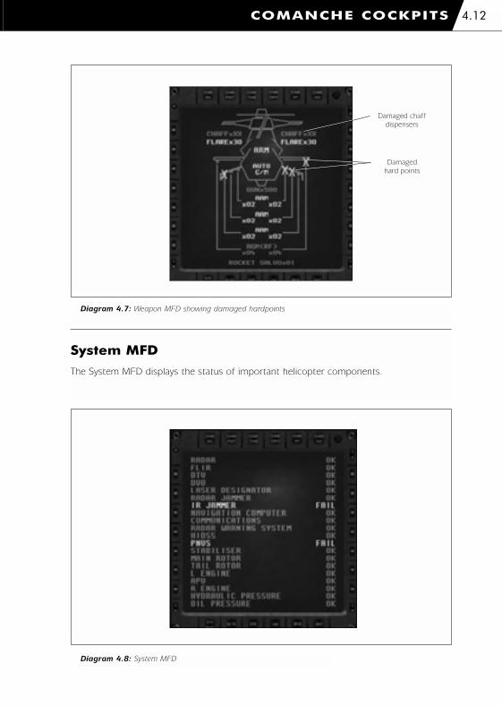
System MFD
The System MFD displays the status of important helicopter components.
COMANCHE COCKPITS 4.12
Diagram 4.8: System MFD
Damaged chaff
dispensers
Damaged
hard points
Diagram 4.7: Weapon MFD showing damaged hardpoints
1036 EE-CH Manual - Chap 4 23/3/00 12:39 pm Page 4.12
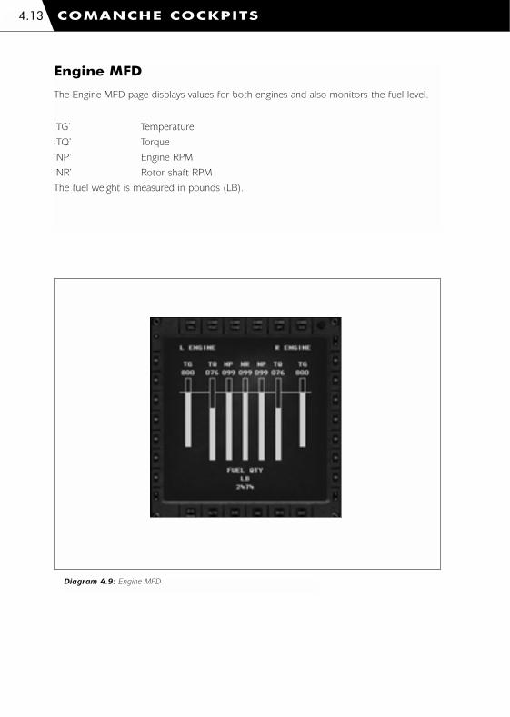
Engine MFD
The Engine MFD page displays values for both engines and also monitors the fuel level.
‘TG’ Temperature
‘TQ’ Torque
‘NP’ Engine RPM
‘NR’ Rotor shaft RPM
The fuel weight is measured in pounds (LB).
COMANCHE COCKPITS4.13
Diagram 4.9: Engine MFD
1036 EE-CH Manual - Chap 4 23/3/00 12:39 pm Page 4.13

Flight MFD
The Flight MFD duplicates the flight and navigation information from the HIDSS navigation
display mode. Refer to the ‘Helmet Integrated Display and Sight System’ section.
Mission MFD
The Mission MFD shows information about the flight group, mission and mission clock.
Flight Group
The company name is displayed followed by a list of the flight group members. The callsign
for each member is displayed. The ‘>’ symbol indicates the group leader. Player’s rank and
names are shown.
The current flight group formation is displayed. The group leader can change the formation
via a radio message (refer to the In-flight ‘Radio Messages’ section).
COMANCHE COCKPITS 4.14
Diagram 4.10: Flight MFD
Engine torque
True airspeed
Current waypoint
identifier
Current waypoint
distance
Time to reach
current waypoint
(HH:MM:SS)
Bank scale Pitch ladder Altitude scale
Pitch datum
Vertical speed
indicator
Altitude
(‘R’ indicates
radar altitude)
Radar altitude
(up to 200 feet)
Command heading Current headingHeading scale
Bank
indicator
1036 EE-CH Manual - Chap 4 23/3/00 12:39 pm Page 4.14
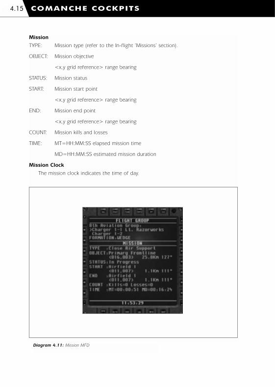
COMANCHE COCKPITS4.15
Mission
TYPE: Mission type (refer to the In-flight ‘Missions’ section).
OBJECT: Mission objective
<x,y grid reference> range bearing
STATUS: Mission status
START: Mission start point
<x,y grid reference> range bearing
END: Mission end point
<x,y grid reference> range bearing
COUNT: Mission kills and losses
TIME: MT=HH:MM:SS elapsed mission time
MD=HH:MM:SS estimated mission duration
Mission Clock
The mission clock indicates the time of day.
Diagram 4.11: Mission MFD
1036 EE-CH Manual - Chap 4 23/3/00 12:39 pm Page 4.15

Helmet Integrated Display and Sight System(HIDSS)
The Comanche pilot's helmet has a built-in display system known as the HIDSS. It is used
much like a conventional ‘head up display’ but has the advantage of always being in the
pilot’s view. If you select a Crew View l+ y which shows a close-up of the pilot’s face
then you can see the HIDSS projected on to the lenses.
The TADS and PNVS (Pilot Night Vision Sensor) optical units are slaved to the HIDSS so that
they ‘look’ where the pilot is looking. The HIDSS can be used to acquire targets simply by
looking at them.
The HIDSS display colour can be cycled to make it easier to read when the outside
conditions change.
K Select next HUD colour
m+ K Select previous HUD colour
The HIDSS has two display modes; 'navigation' and 'combat'
HIDSS In Navigation Mode
COMANCHE COCKPITS 4.16
Engine torque
Bank scale
True airspeed
IHADSS centre
datum
Current waypoint
identifier
Time to reach
current waypoint
(HH:MM:SS)
Current waypoint
distance
Pitch ladder Altitude scale
Barometric
altitude
Vertical speed
indicator
Radar altitude
(up to 1,500 feet)
Radar altitude
(up to 200 feet)
Command heading Current heading Heading scale
Diagram 4.12: HIDSS in navigation mode
1036 EE-CH Manual - Chap 4 23/3/00 12:39 pm Page 4.16

HIDSS Centre Datum
Indicates the centre of the display.
Heading Scale and Command Heading
The heading scale is calibrated every 30 degrees. The command heading indicates the
direction to the next waypoint.
Pitch Ladder
The pitch ladder indicates the helicopter’s pitch and bank attitude. Pitch bars are calibrated
every 10 degrees. Solid lines are draw above the horizon and dashed lines are drawn below
the horizon.
Bank Scale
The bank scale indicates the helicopter's bank angle up to 30 degrees.
True Airspeed
True airspeed in knots.
Barometric Altitude
Digital readout of the barometric altitude (height above sea level) in feet.
Radar Altitude
Digital readout of the radar altitude (height above ground) in feet. This value is valid up to
1,500 feet.
The analogue radar altitude bar is valid up to 200 feet and is read against the altitude scale.
Vertical Speed Indicator
When the vertical speed indicator is above the altitude scale centre line the helicopter is
climbing. When it is below the centre line the helicopter is sinking. The full scale deflection
of the vertical speed indicator is +/-1,000 feet per minute.
Engine Torque
Digital readout of the engine torque.
Current Waypoint
The current waypoint identifier, distance and time to reach (hours:minutes:seconds) are
shown in the lower left corner of the display.
COMANCHE COCKPITS4.17
1036 EE-CH Manual - Chap 4 23/3/00 12:39 pm Page 4.17
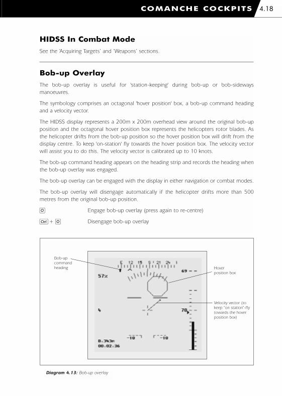
HIDSS In Combat Mode
See the ‘Acquiring Targets’ and ‘Weapons’ sections.
Bob-up Overlay
The bob-up overlay is useful for 'station-keeping' during bob-up or bob-sideways
manoeuvres.
The symbology comprises an octagonal 'hover position' box, a bob-up command heading
and a velocity vector.
The HIDSS display represents a 200m x 200m overhead view around the original bob-up
position and the octagonal hover position box represents the helicopters rotor blades. As
the helicopter drifts from the bob-up position so the hover position box will drift from the
display centre. To keep 'on-station' fly towards the hover position box. The velocity vector
will assist you to do this. The velocity vector is calibrated up to 10 knots.
The bob-up command heading appears on the heading strip and records the heading when
the bob-up overlay was engaged.
The bob-up overlay can be engaged with the display in either navigation or combat modes.
The bob-up overlay will disengage automatically if the helicopter drifts more than 500
metres from the original bob-up position.
O Engage bob-up overlay (press again to re-centre)
l+ O Disengage bob-up overlay
COMANCHE COCKPITS 4.18
Diagram 4.13: Bob-up overlay
Bob-up
command
heading Hover
position box
Velocity vector (to
keep “on station”-fly
towards the hover
position box)
1036 EE-CH Manual - Chap 4 23/3/00 12:39 pm Page 4.18
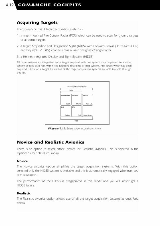
Acquiring Targets
The Comanche has 3 target acquisition systems:-
1. a mast-mounted Fire Control Radar (FCR) which can be used to scan for ground targets
or airborne targets
2. a Target Acquisition and Designation Sight (TADS) with Forward-Looking Infra-Red (FLIR)
and Daylight TV (DTV) channels plus a laser designator/range-finder.
3. a Helmet Integrated Display and Sight System (HIDSS)
All three systems are integrated and a target acquired with one system may be passed to another
system as long as it falls within the targeting restraints of that system. Any target which has been
acquired is kept on a target list and all of the target acquisition systems are able to cycle through
this list.
Novice and Realistic Avionics
There is an option to select either ‘Novice’ or ‘Realistic’ avionics. This is selected in the
Options Screen ‘Realism’ menu.
Novice
The Novice avionics option simplifies the target acquisition systems. With this option
selected only the HIDSS system is available and this is automatically engaged whenever you
arm a weapon.
The performance of the HIDSS is exaggerated in this mode and you will never get a
HIDSS failure.
Realistic
The Realistic avionics option allows use of all the target acquisition systems as described
below.
COMANCHE COCKPITS4.19
Insert Home Page Up
Delete End Page Down
Air radar IHADSSGround radar
FLIR DTV
Radar
Select Target Acquisition System
TADS
Diagram 4.14: Select target acquisition system
1036 EE-CH Manual - Chap 4 23/3/00 12:39 pm Page 4.19

CP/G Assistance: Target ID
The Co-pilot/Gunner (CP/G) can assist you to identify targets. There are 3 levels of
assistance; 'Novice', 'Realistic' and 'Off'. This is selected in the Options Screen ‘Realism’
menu.
Novice
The CP/G identifies the target immediately and reports them using simplistic names such as
‘Enemy Tank’ and ‘Allied Aircraft’.
Realistic
The CP/G attempts to make a visual identification (using the TADS where possible). It may
take the CP/G a few moments to make the identification depending on the target range and
adverse weather conditions. During this time the message ‘CP/G IDENTIFYING...’ is
displayed instead of the target name. If there is no line of sight to the target then no
identification can be made. If you have selected an inappropriate TADS system (you cannot
use FLIR in heavy rain or DTV at night) the message ‘LOW LIGHT’ is displayed in place of
the target name. In this case select a more suitable system. Once the identification is made
the NATO reporting name is given for the target and you must decide if it is an allied or
enemy target.
Off
The CP/G gives you no help whatsoever. Once a target has been selected then use the TADS
systems to make the identification yourself. The 'Recognition Guide' will assist you in
spotting key recognition features.
COMANCHE COCKPITS 4.20
1036 EE-CH Manual - Chap 4 23/3/00 12:39 pm Page 4.20

Fire Control Radar
The Fire Control Radar scans for targets and a symbolic image of the returns is shown on
the MFD display. The radar can only acquire targets to which it has line of sight (LOS). If an
acquired target masks behind buildings or terrain features the radar will still display the
target but the target category symbol will change. If the target was moving the radar will
attempt to interpolate the target's new position. Target symbols are displayed using two
different colours for clarity.
Target Categories LOS No LOS
Wheeled vehicle
Tracked vehicle
Air defence unit
Aircraft
Helicopter
Ship
Structure
Using radar will alert enemy targets of your presence and may attract hostile fire. Ensure
that you switch the radar off when you have finished using it!
COMANCHE COCKPITS4.21
1036 EE-CH Manual - Chap 4 23/3/00 12:39 pm Page 4.21

Ground Radar
COMANCHE COCKPITS 4.22
Diagram 4.15: Ground radar display
Diagram 4.16: Ground radar controls
Num Lock
7
/ -
8
*
9
4 5 6
1 2 3
0 Del Enter
+
Activatesingle radarsweep
Single/continuousradar sweep
+ Scan size
Scan centre Scan rightScan left
– Scan size Auto-target
> Target
< Target (shift)
Switch off (ctrl)
Lock/unlocktarget
+ Range Display alliedaircraft
– Range
Target Acquisition System Controls
+ = Increase – = Decrease> = Select Next< = Select Previous
Target priority Current
heading
Heading scale
Target locked
Target identity
(see CP/G assistance)
No line of
sight to target
Target range
MFD ‘focus’
light
Maximum
scan limits
Auto-target
engaged
Selected target
Radar range
Scan position
Scan limits
Radar clutter
TADS fields of
view markerTADS Fields
of regard box
1036 EE-CH Manual - Chap 4 23/3/00 12:39 pm Page 4.22
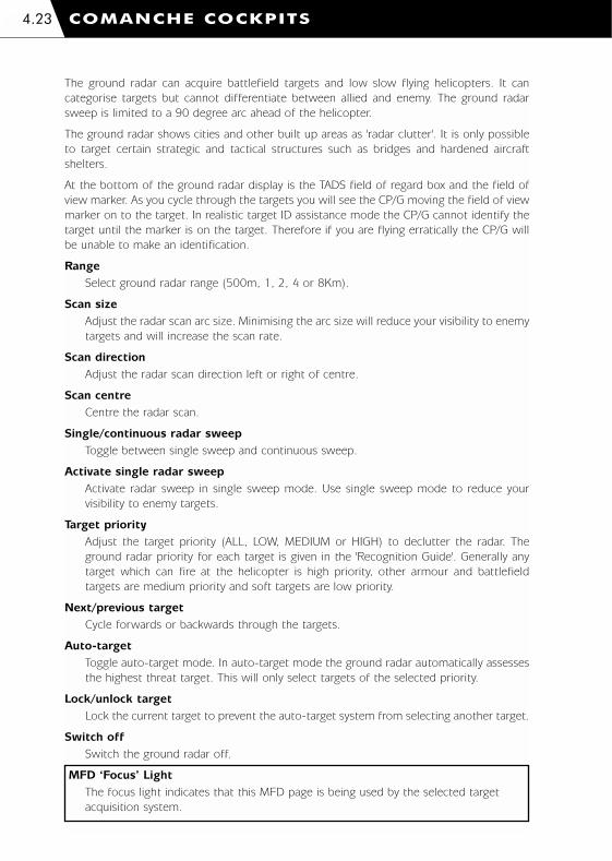
The ground radar can acquire battlefield targets and low slow flying helicopters. It can
categorise targets but cannot differentiate between allied and enemy. The ground radar
sweep is limited to a 90 degree arc ahead of the helicopter.
The ground radar shows cities and other built up areas as 'radar clutter'. It is only possible
to target certain strategic and tactical structures such as bridges and hardened aircraft
shelters.
At the bottom of the ground radar display is the TADS field of regard box and the field of
view marker. As you cycle through the targets you will see the CP/G moving the field of view
marker on to the target. In realistic target ID assistance mode the CP/G cannot identify the
target until the marker is on the target. Therefore if you are flying erratically the CP/G will
be unable to make an identification.
Range
Select ground radar range (500m, 1, 2, 4 or 8Km).
Scan size
Adjust the radar scan arc size. Minimising the arc size will reduce your visibility to enemy
targets and will increase the scan rate.
Scan direction
Adjust the radar scan direction left or right of centre.
Scan centre
Centre the radar scan.
Single/continuous radar sweep
Toggle between single sweep and continuous sweep.
Activate single radar sweep
Activate radar sweep in single sweep mode. Use single sweep mode to reduce your
visibility to enemy targets.
Target priority
Adjust the target priority (ALL, LOW, MEDIUM or HIGH) to declutter the radar. The
ground radar priority for each target is given in the 'Recognition Guide'. Generally any
target which can fire at the helicopter is high priority, other armour and battlefield
targets are medium priority and soft targets are low priority.
Next/previous target
Cycle forwards or backwards through the targets.
Auto-target
Toggle auto-target mode. In auto-target mode the ground radar automatically assesses
the highest threat target. This will only select targets of the selected priority.
Lock/unlock target
Lock the current target to prevent the auto-target system from selecting another target.
Switch off
Switch the ground radar off.
MFD ‘Focus’ Light
The focus light indicates that this MFD page is being used by the selected target
acquisition system.
COMANCHE COCKPITS4.23
1036 EE-CH Manual - Chap 4 23/3/00 12:39 pm Page 4.23

Air Radar
COMANCHE COCKPITS 4.24
Diagram 4.17: Air radar display
Diagram 4.18: Air radar controls
Num Lock
7
/ -
8
*
9
4 5 6
1 2 3
0 Del Enter
+
Pan up
Pan centre Pan rightPan left
Pan down
> Target
< Target (shift)
Switch off (ctrl)
Lock/unlocktarget
+ Zoom
– Zoom
Target Acquisition System Controls
+ = Increase – = Decrease> = Select Next< = Select Previous
Enemy or all targets
Target identity
(see CP/G assistance)Selected target
Scan centre
Target range
Scan position
Radar range
MFD ‘focus’
light
Target locked
Scan limits
Auto-target
engaged
1036 EE-CH Manual - Chap 4 23/3/00 12:39 pm Page 4.24

COMANCHE COCKPITS4.25
The air radar can acquire airborne targets. It can categorise targets and identify between
allied and enemy. The air radar can sweep through 360 degrees.
Air radar contacts will ‘timeout’ unless they are reswept.
Range
Select air radar range (500m, 1, 2, 4 or 8Km).
Scan size
Adjust the radar scan arc size. Minimising the arc size will reduce your visibility to enemy
targets and will increase the scan rate.
Scan direction
Adjust the radar scan direction left or right of centre.
Scan centre
Centre the radar scan.
Single/continuous radar sweep
Toggle between single sweep and continuous sweep.
Activate single radar sweep
Activate radar sweep in single sweep mode. Use single sweep mode to reduce your
visibility to enemy targets.
Display allied aircraft
Toggle display ALL aircraft targets or ENEMY targets only.
Next/previous target
Cycle forwards or backwards through the targets.
Auto-target
Toggle auto-target mode. In auto-target mode the air radar automatically assesses the
highest threat target.
Lock/unlock target
Lock the current target to prevent the auto-target system from selecting another target.
Switch off
Switch the air radar off.
MFD ‘Focus’ Light
The focus light indicates that this MFD page is being used by the selected target
acquisition system.
1036 EE-CH Manual - Chap 4 23/3/00 12:39 pm Page 4.25

Target Acquisition and Designation Sight (TADS)
COMANCHE COCKPITS 4.26
Diagram 4.19: TADS display
Diagram 4.20: TADS controls
Num Lock
7
/ -
8
*
9
4 5 6
1 2 3
0 Del Enter
+
Pan up
Pan centre Pan rightPan left
Pan down
> Target
< Target (shift)
Switch off (ctrl)
Lock/unlocktarget
+ Zoom
– Zoom
Target Acquisition System Controls
+ = Increase – = Decrease> = Select Next< = Select Previous
Sensor type
(FLIR or DTV)
TADS heading
(not helicopter heading)
Field of view
Target identity
(see CP/G assistance)
TADS field of
view markerTADS field of
regard box
Target range
TADS boresight
datum
Target
TADS gates
MFD ‘focus’
light
Target locked
1036 EE-CH Manual - Chap 4 23/3/00 12:39 pm Page 4.26
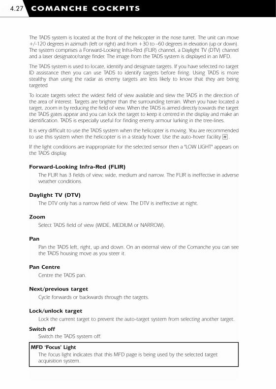
COMANCHE COCKPITS4.27
The TADS system is located at the front of the helicopter in the nose turret. The unit can move
+/-120 degrees in azimuth (left or right) and from +30 to –60 degrees in elevation (up or down).
The system comprises a Forward-Looking Infra-Red (FLIR) channel, a Daylight TV (DTV) channel
and a laser designator/range finder. The image from the TADS system is displayed in an MFD.
The TADS system is used to locate, identify and designate targets. If you have selected no target
ID assistance then you can use TADS to identify targets before firing. Using TADS is more
stealthy than using the radar as enemy targets are less likely to know that they are being
targeted
To locate targets select the widest field of view available and slew the TADS in the direction of
the area of interest. Targets are brighter than the surrounding terrain. When you have located a
target, zoom in by reducing the field of view. When the TADS is aimed directly towards the target
the TADS gates appear and you can lock the target to keep it centred in the display and make an
identification. TADS is especially useful for finding enemy armour lurking in the tree-lines.
It is very difficult to use the TADS system when the helicopter is moving. You are recommended
to use this system when the helicopter is in a steady hover. Use the auto-hover facility H.
If the light conditions are inappropriate for the selected sensor then a "LOW LIGHT" appears on
the TADS display.
Forward-Looking Infra-Red (FLIR)
The FLIR has 3 fields of view; wide, medium and narrow. The FLIR is ineffective in adverse
weather conditions.
Daylight TV (DTV)
The DTV only has a narrow field of view. The DTV is ineffective at night.
Zoom
Select TADS field of view (WIDE, MEDIUM or NARROW).
Pan
Pan the TADS left, right, up and down. On an external view of the Comanche you can see
the TADS housing move as you steer it.
Pan Centre
Centre the TADS pan.
Next/previous target
Cycle forwards or backwards through the targets.
Lock/unlock target
Lock the current target to prevent the auto-target system from selecting another target.
Switch off
Switch the TADS system off.
MFD ‘Focus’ Light
The focus light indicates that this MFD page is being used by the selected target
acquisition system.
1036 EE-CH Manual - Chap 4 23/3/00 12:39 pm Page 4.27
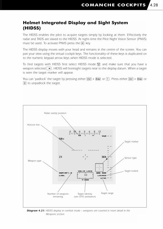
Helmet Integrated Display and Sight System(HIDSS)The HIDSS enables the pilot to acquire targets simply by looking at them. Effectively the
radar and TADS are slaved to the HIDSS. At night-time the Pilot Night Vision Sensor (PNVS)
must be used. To activate PNVS press the N key.
The HIDSS display moves with your head and remains in the centre of the screen. You can
pan your view using the virtual cockpit keys. The functionality of these keys is duplicated on
to the numeric keypad arrow keys when HIDSS mode is selected.
To find targets with HIDSS first select HIDSS mode _ and make sure that you have a
weapon selected i. HIDSS will boresight targets near to the display datum. When a target
is seen the target marker will appear.
You can ‘padlock’ the target by pressing either l+ j or 1. Press either l+ j or
0 to unpadlock the target.
COMANCHE COCKPITS 4.28
Diagram 4.21: HIDSS display in combat mode – weapons are covered in more detail in the
Weapons section
Horizon line
Radar sweep position
Target marker
Sensor type
Target locked
Target rangeTarget identity
(see CP/G assistance)
Number of weapons
remaining
Weapon type
1036 EE-CH Manual - Chap 4 23/3/00 12:39 pm Page 4.28

The weapon type indicates the selected weapon:-
‘Gun’ 20mm Gatling gun
‘AAM’ AIM-92 Stinger IR guided air-to-air missiles
‘AGM(RF)’ AGM-114L Longbow Hellfire radar guided anti-tank missiles
‘AGM(LSR)’ AGM-114K Hellfire II laser guided anti-tank missiles
‘RKT(HE)’ Hydra 70 M255 70 mm high explosive unguided rockets
‘RKT(MP)’ Hydra 70 M261 70 mm multi-purpose unguided rockets
The sensor type indicates the active target acquisition system:-
‘GND RDR’ Ground radar
‘AIR RDR’ Air radar
‘FLIR’ Forward-Looking Infra-Red
‘DTV’ Daylight TV
‘HIDSS’ HIDSS
The target lock type indicates if the weapon has a valid lock else the reason for lock failure:-
‘NO ACQUIRE’ No target acquisition system is active
‘NO WEAPON’ No weapon is selected
‘NO TARGET’ No target has been designated
‘INVALID TARGET’ The target is unsuitable for the weapon
‘SEEKER LIMIT’ The target exceeds the weapon seeker limit
‘NO LOS’ No line of sight to the target
‘NO BORESIGHT’ The target must be ahead of the helicopter for unguided rockets
‘MIN RANGE’ The target is too near
‘MAX RANGE’ The target is too far
‘VALID LOCK’ The lock is good
COMANCHE COCKPITS4.29
Diagram 4.22: HIDSS controls
Num Lock
7
/ -
8
*
9
4 5 6
1 2 3
0 Del Enter
+
Pan up (alt)
Pan right(alt)
Pan left(alt)
Pan down
(alt)
> Target
< Target (shift)
Switch off (ctrl)
Lock/unlocktarget
Target Acquisition System Controls
+ = Increase – = Decrease> = Select Next< = Select Previous
1036 EE-CH Manual - Chap 4 23/3/00 12:39 pm Page 4.29
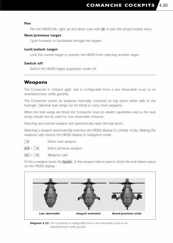
Pan
Pan the HIDSS left, right up and down (use with g to pan the virtual cockpit view).
Next/previous target
Cycle forwards or backwards through the targets.
Lock/unlock target
Lock the current target to prevent the HIDSS from selecting another target.
Switch off
Switch the HIDSS target acquisition mode off.
Weapons
The Comanche is ‘mission agile’ and is configurable from a low observable scout to an
attack/precision strike gunship.
The Comanche carries its weapons internally, mounted on bay doors either side of the
fuselage. Optional stub wings can be fitted to carry more weapons.
When the stub wings are fitted the Comanche loses its stealth capabilities and so the stub
wings should not be used for low observable missions.
Selecting any internal weapon will automatically open the bay doors.
Selecting a weapon automatically switches the HIDSS display to combat mode. Making the
weapons safe returns the HIDSS display to navigation mode.
i Select next weapon
m+ i Select previous weapon
l+ i Weapons safe
To fire a weapon press the n. If the weapon fails to launch check the lock failure status
on the HIDSS display.
COMANCHE COCKPITS 4.30
Diagram 4.23: The Comanche is configurable from a low observable scout to an
attack/precision strike gunship
Low observable Integral armement Attack/precision strike
1036 EE-CH Manual - Chap 4 23/3/00 12:39 pm Page 4.30

20 mm Gatling Gun
The Comanche is equipped with a stowable three-barrel M197 20 millimetre Gatling gun
loaded with 500 rounds of ammunition.
The gun automatically tracks the selected target and can be rotated +/-120 degrees in
azimuth (left or right) and from +10 to -60 degrees in elevation (up or down).
The Gatling gun can be used against ground or air targets.
Type 20 mm Gatling gun
Rate of fire 750 rounds per minute
Maximum range 1,600 metres
Muzzle velocity 884 metres per second
Weight 0.257 Kg
COMANCHE COCKPITS4.31
Diagram 5.24: HIDSS display for the gun showing an out of range target
Target marker
without valid lock
Target out
of range
Diagram 5.25: HIDSS display for the gun showing a valid target lock
Target marker
with valid lock
1036 EE-CH Manual - Chap 4 23/3/00 12:39 pm Page 4.31

AIM-92 Stinger
The Comanche carries Stinger short-range air-to-air guided missiles. A maximum of 12 can
be carried internally on the bay doors and a maximum of 16 can be carried on the stub
wings – 28 Stingers in total.
The Stinger is a heat seeking missile and is effective against airborne targets. If a ground
target is selected then "INVALID TARGET" is displayed on the HIDSS display.
Enemy targets will use flares and IR jammers to distract this missile.
Type short-range air-to-air
Guidance infra-red homing (fire-and-forget)
Maximum range 5,000 metres
Cruise speed Mach 2.0
Seeker field of view 80°
Weight 13.6 Kg
When the Stinger is seeking for a target a pair of dashed concentric circles move around the
HIDSS display to indicate the seeker head position. When a valid lock on has been achieved
the dashed circles become solid and indicate the target position. Also a tone is emitted to
indicate the valid lock.
COMANCHE COCKPITS 4.32
Diagram 4.27: HIDSS display for a Stinger showing a valid target lock
Diagram 4.26: HIDSS display for a Stinger seeking a target
Target marker
Seeker head
position
Turn left to get
a target lock
Current target
is outside the
seeker limit
1036 EE-CH Manual - Chap 4 23/3/00 12:39 pm Page 4.32

Hellfires
The Comanche carries Hellfire short-range anti-tank guided missiles. A maximum of 6 can
be carried internally on the bay doors and a maximum of 8 can be carried on the stub wings
– 14 Hellfires in total.
There are two types of Hellfire missile; the AGM-114L Longbow Hellfire and the AGM-114K
Hellfire II. Hellfires are effective against armoured battlefield targets but may also be used
against slow moving airborne targets.
The AGM-114L Longbow Hellfire is an active radar guided missile. This is fire and forget
missile. When the missile has been launched you can select another target and launch
another missile.
The AGM-114K Hellfire II is a semi-active laser guided missile. The missile requires a the
target to be 'painted' with laser.
Hellfire missiles can be launched in one of two modes; lock on before launch (LOBL) and
lock on after launch (LOAL). The lock on mode is toggled with the L key.
In LOBL mode the missile requires a line of sight to the target. If a radar guided Hellfire is
used then the helicopter can mask behind cover after the missile is launched. If a laser
guided Hellfire is used then the target must be laser designated throughout the missiles
flight. The missile's time to target (in seconds) is shown in the lower left corner of the
IHADSS display. If more than one missile is launched then the flight time of the most
recently launched missile is shown.
In LOAL mode the missiles can be launched from behind cover. The missile follows a high
launch profile. When a target is selected the missile steers towards it but only if the target
is within the missile's seeker limits. With radar guided Hellfires it is not necessary for the
helicopter to unmask but with laser guided missiles it is necessary to unmask in order to
designate the target.
Hellfire ‘LOAL’ Deployment
When Hellfire missiles are deployed in lock-on after launch ‘LOAL’ mode they follow a
high launch profile. That is, they zoom climb to about 300m before pitching over so
that they can 'see' ground targets.
The initial zoom climb uses energy and shortens the effective range of the missile. The
missile cannot see ground targets until it has pitched over and is looking towards the
ground. This increases the minimum range of the missile.
The target lock type will show a ‘VALID LOCK’ in LOAL mode if the target range is
between 1.5 Km and 5.0 Km. These are a guideline only. Other factors have to be
considered such as the height difference (between the helicopter and the target) and
the target azimuth error (the horizontal angular error between the display centre and
the target).
COMANCHE COCKPITS4.33
1036 EE-CH Manual - Chap 4 23/3/00 12:39 pm Page 4.33

COMANCHE COCKPITS 4.34
Diagram 4.28: HIDSS display for a Hellfire missile in LOBL launch mode
showing an invalid target lock
Target marker
showing invalid
target lock
Lock on before
launch
Diagram 4.29: IHIDSS display for a Hellfire missile in LOBL launch
mode showing a valid target lock
Lock on before
launch
Missile’s time to
target (seconds)
Target marker
showing invalid
lock
Type short-range anti-tank guided missile (ATGM)
Guidance active radar (AGM-114L) semi-active laser (AGM-114K)
Maximum range 8,000 metres
Cruise speed Mach 1.3
Seeker field of view 60°
Weight 45.0 Kg
1036 EE-CH Manual - Chap 4 23/3/00 12:39 pm Page 4.34

COMANCHE COCKPITS4.35
Diagram 4.30: HIDSS display for a Hellfire missile in LOAL launch mode
showing an invalid target lock
Diagram 4.31: HIDSS display for a Hellfire missile in LOAL launch mode
showing a valid target lock
Invalid target lock
Lock on after
launch
Target marker
Lock on after
launch
Valid target lock
1036 EE-CH Manual - Chap 4 23/3/00 12:39 pm Page 4.35

COMANCHE COCKPITS 4.36
Hydra 70 Rockets
The Comanche carries Hydra 70 mm folding-fin aerial rockets (FFARs). These rockets are
unguided so it is necessary to boresight the target by steering the helicopter towards it. Use
the forward cockpit view o.
Hydra rockets can only be carried on the stub wings and they are mounted in pods of 19
giving a maximum capacity of 38.
Rockets can be fired in salvos to increase the damage area and kill probability.
S Increase salvo size
m+ S Decrease salvo size
There are two types of warheads; the M255 high explosive (HE) warhead and the M261
multi-purpose sub-munition (MPSM) warhead.
The M255 HE warhead is effective against soft battlefield targets and helicopters. The
M261 MPSM warhead is effective against armoured vehicles.
The rocket pods have automatic adjustable elevation (from +4.9 degrees to -15.0 degrees).
It is only necessary to line the helicopter's heading up with the target if the elevation is
within limits. This makes using rockets in the Comanche far easier than in the Hokum and
the kill probability is increased.
The rocket pods will not elevate at speeds in excess of 100 knots. If the helicopter's speed
is above this limit the rockets must be boresighted manually as in the Hokum.
Type folding-fin aerial rocket
Maximum range 5,000 metres
Weight 6.0 Kg
The HIDSS display shows the target marker and an 'I-beam'. It is necessary to line up the
target marker with the I-beam in order to get a valid lock. With airborne targets the I-beam
must be lined up with the computed intercept point instead.
1036 EE-CH Manual - Chap 4 23/3/00 12:39 pm Page 4.36

COMANCHE COCKPITS4.37
Diagram 4.34: HIDSS display for unguided rockets showing I-beam not lined up
with air target intercept point
Diagram 4.33: HIDSS display for unguided rockets showing I-beam lined
up with ground target
Computed
intercept point
Solid I-beam
indicating valid lock
Target marker
Diagram 4.32: HIDSS display for unguided rockets showing I-beam not lined up
with ground target
Dashed I-beam
marker indicating
no boresightTarget marker
Rocket salvo size
Steer towards
I-beam
Target marker
Steer towards
I-beam
Dashed I-beam
indicating
no boreshight
➝➝
1036 EE-CH Manual - Chap 4 23/3/00 12:39 pm Page 4.37

COMANCHE COCKPITS 4.38
Diagram 4.35: HIDSS display for unguided rockets showing I-beam lined up
with air target intercept point
Target marker
Computerised
intercept point
Solid I-beam
indicating
valid lock
Countermeasures
When the ASE display indicates a radar or infra-red threat then the following
countermeasures may be used to increase survivability.
Radar Jammer
The radar jammer is used to fool enemy radar of the helicopter’s position by creating
spurious targets.
J radar jammer on/off
IR Jammer
The IR jammer pumps out intense IR radiation to confuse the seeker head of an
incoming IR missile to break lock.
I IR jammer on/off
Chaff
Chaff comprises millions of strips of aluminised Mylar film which when released
generate a cloud of radar signature to fool incoming radar guided missiles.
C release chaff cartridge
Flares
Flares are hot pyrotechnic cartridges used to create false targets for incoming IR
missiles.
F release flare cartridge
The disadvantage of electronic countermeasures (ECM) such as the radar and IR jammers
is that they unmask the helicopter and increase its visibility. They should be used as
required.
The disadvantage of chaff and flares is that they run out! The Comanche carries 60 of each.
1036 EE-CH Manual - Chap 4 23/3/00 12:39 pm Page 4.38

COMANCHE COCKPITS4.39
Automatic CountermeasuresThe Co-pilot/Gunner can assist you with operating the countermeasures.
This option is selected in the Options Screen ‘Realism’ menu and can also be changed
in-flight.
l+ C automatic countermeasures on/off.
Pilot Night Vision Sensor (PNVS)
The Comanche pilot has night vision sensor to aid flying at night.
N PNVS on/off
Windshield Wipers
The Comanche is not fitted with windshield wipers as they would spoil the stealth
characteristics of the helicopter. In wet weather conditions concealed air blowers
automatically engage to clear the windshield.
1036 EE-CH Manual - Chap 4 23/3/00 12:39 pm Page 4.39

5. HOKUM COCKPITS
1036 EE-CH Manual - Chap 5 23/3/00 12:41 pm Page 1

HOKUM COCKPITS5.1
Diagram 5.1: Cockpit view (pilot left, co-pilot right)
Diagram 5.2: Side-by-side cockpit configuration
1036 EE-CH Manual - Chap 5 23/3/00 12:41 pm Page 5.1

Instrument Panel
The Hokum has a side-by-side cockpit configuration. The pilot sits in the left (port) seat
and the co-pilot (CP/G) sits in the right (starboard) seat. You can assume either of the
crew roles.
Each pilot has two multi-function displays (MFDs). The indicator lights and backup
instruments are located on the central console. The co-pilot has binoculars for the ventrally
mounted periscope.
Refer to the In-flight ‘Views’ section for details of the cockpit views.
Airspeed Indicator
The airspeed indicator shows the indicated airspeed of the helicopter and also the sideslip
(sideways velocity).
Indicated Airspeed
Scale km/h * 10
Full scale deflection -50 to 450 km/h
Sideslip
Scale km/h * 10
Full scale deflection +/-100 km/h
Barometric Altimeter
The barometric altimeter shows the barometric altitude (height above sea level).
Barometric Altitude
Large needle scale metres X 100 (one revolution = 1,000 metres)
Small needle scale metres X 1,000 (one revolution = 10,000 metres)
HOKUM COCKPITS 5.2
1036 EE-CH Manual - Chap 5 23/3/00 12:41 pm Page 5.2

HOKUM COCKPITS5.3
Vertical Speed Indicator
The vertical speed indicator shows the rate of climb.
Climb
Descend
0 30
5
5 20
2010
10
Rate of Climb
Scale metres per minute / 10 (scale is non-linear)
Full scale deflection +/-300 metres per minute
Artificial Horizon
The artificial horizon shows the helicopter pitch and roll attitude relative to the ground.
Diagram 5.3: Direction of climb and descent
Diagram 5.4: Pitch up/down rolled left/right
Pitched up Rolled left
Pitched down Rolled right
1036 EE-CH Manual - Chap 5 23/3/00 12:41 pm Page 5.3

HOKUM COCKPITS 5.4
Standby Compass
The standby compass shows the helicopter’s heading.
90 East
‘C’ North
18 South
27 West
Master Caution Light
The master caution light flashes, accompanied by an audible warning, to indicate that there
is a problem. The problem will be indicated by the warning lights or EKRAN Display. To
acknowledge the caution press M. This extinguishes the master caution light and silences
the audible warning.
Fire Warning & Extinguisher Lights
The fire warning lights indicate if either engine or the auxiliary power unit (APU) is on fire.
In case of a fire use the fire extinguisher. The fire extinguisher can only be used once per
mission.
L ENG Left engine fire
APU APU fire
R ENG Right engine fire
l+ F Activate fire extinguisher
The fire extinguisher light indicates if the fire extinguishers have been used.
1036 EE-CH Manual - Chap 5 23/3/00 12:41 pm Page 5.4

HOKUM COCKPITS5.5
Warning Lights
TRQ Engine over torque
RTR RPM Low main rotor RPM
FUEL LOW Low fuel level (<25% maximum fuel level)
HYD PRES Low hydraulic pressure
OIL PRES Low or high engine oil pressure
OIL TEMP High engine oil temperature
Status Lights
RTR BRK Rotor brake engaged
WHL BRK Wheel brake engaged
NAV LTS Navigation lights on
HOV HLD Hover-hold active
ALT HLD Altitude-hold active
AUT PLT Auto-pilot active
RDR Radar active
LSR Laser active
RDR JAM Radar jammer active
IR JAM Infra-red jammer active
AUT C/M Auto-countermeasures active
AUT TWD TWD auto-paging active
Gear (Undercarriage) Lights
The GEAR UP/DOWN light is illuminated green when the gear is fully down and red when
the gear is fully up. The light flashes when the gear is in a transitional state (raising or
lowering). The GEAR DAMAGED light indicates a gear failure.
l+ G Raise/lower gear
1036 EE-CH Manual - Chap 5 23/3/00 12:41 pm Page 5.5
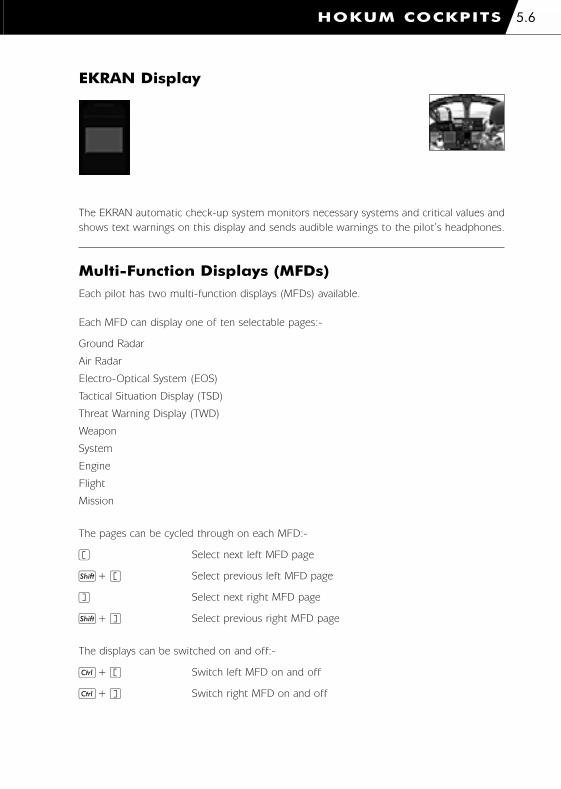
HOKUM COCKPITS 5.6
EKRAN Display
The EKRAN automatic check-up system monitors necessary systems and critical values and
shows text warnings on this display and sends audible warnings to the pilot’s headphones.
Multi-Function Displays (MFDs)Each pilot has two multi-function displays (MFDs) available.
Each MFD can display one of ten selectable pages:-
Ground Radar
Air Radar
Electro-Optical System (EOS)
Tactical Situation Display (TSD)
Threat Warning Display (TWD)
Weapon
System
Engine
Flight
Mission
The pages can be cycled through on each MFD:-
( Select next left MFD page
m+ ( Select previous left MFD page
) Select next right MFD page
m+ ) Select previous right MFD page
The displays can be switched on and off:-
l+ ( Switch left MFD on and off
l+ ) Switch right MFD on and off
1036 EE-CH Manual - Chap 5 23/3/00 12:41 pm Page 5.6
There are shortcut keys to select any page on either MFD.
Left MFD:-
l+ 1 Ground Radar
l+ 2 Air Radar
l+ 3 Electro-Optical System (EOS)
l+ 4 Tactical Situation Display (TSD)
l+ 5 Threat Warning Display (TWD)
l+ 6 Weapon
l+ 7 System
l+ 8 Engine
l+ 9 Flight
l+ 0 Mission
Right MFD:-
g+ 1 Ground Radar
g+ 2 Air Radar
g+ 3 Electro-Optical System (EOS)
g+ 4 Tactical Situation Display (TSD)
g+ 5 Threat Warning Display (TWD)
g+ 6 Weapon
g+ 7 System
g+ 8 Engine
g+ 9 Flight
g+ 0 Mission
Ground Radar MFD
See the 'Acquiring Targets' section.
Air Radar MFD
See the 'Acquiring Targets' section.
Electro-Optical System (EOS) MFD
See the 'Acquiring Targets' section.
HOKUM COCKPITS5.7
1036 EE-CH Manual - Chap 5 23/3/00 12:41 pm Page 5.7

Tactical Situation Display (TSD) MFD
The Tactical Situation Display shows the moving map, navigation information, targets, anti-
aircraft threats and air threats and is essential during combat situations.
Helicopter Datum
The TSD shows a plan view of the battlefield with the helicopter located at the bottom
of the display.
Declutter Level
The TSD has 3 declutter levels:-
ALL Display both target and navigation information
TGT Display target information only
NAV Display navigation information only
D Next TSD declutter level
m+ D Previous TSD declutter level
TSD Range
The TSD range is selectable between 2, 5, 10 and 25Km. This also changes the range
of the TWD display.
E Next TSD range
m+E Previous TSD range
HOKUM COCKPITS 5.8
Diagram 5.5: TSD MFD (target declutter)
Threat range
circles
Selected target
Helicopter datum
Sensor type
TSD range
Declutter level
(target)
Radar scan limits
Targets/Threats
Selected Target
range
Threat is targeting
helicopter (Flashes when
a missile is launched)
1036 EE-CH Manual - Chap 5 23/3/00 12:41 pm Page 5.8

Sensor Type
NO ACQ No sensor is active
FCR/GND Ground radar
FCR/AIR Air radar
EOSS/FLIR EOS forward-looking infra-red
EOS/LLLTV EOS daylight TV
EOS/SCOPE EOS periscope
Radar Scan Limits
The scan limits of the active ground or air radar.
Targets
Targets are displayed using the radar symbology (see the 'Acquiring Targets' section).
Target symbols are displayed using two different colours for clarity. The selected target
is marked by a cursor and it's range is shown in the lower right corner of the display.
Threats
Threat range circles are drawn around enemy anti-aircraft units. If the helicopter is
inside the circle then you are in range of enemy fire. If a threat (anti-aircraft or airborne)
is targeting the helicopter then a line is drawn between the threat and the helicopter
datum. When this line flashes a missile has been launched.
Waypoint Route
The waypoint route shows the planned mission route. Information for the current
waypoint is shown in the lower left corner of the display.
HOKUM COCKPITS5.9
Diagram 5.6: TSD MFD (navigation declutter)
River (Blue)
Current waypoint
range
Current waypoint
identifier
To reach current waypoint (HH:MM:SS)
Road (Yellow)
Contour lines
(dark amber)
Declutter level
(navigation)
Waypoints
Waypoint route
1036 EE-CH Manual - Chap 5 23/3/00 12:41 pm Page 5.9

Threat Warning Display (TWD) MFD
The Threat Warning Display shows anti-aircraft, airborne and missile threats. It also shows
if jamming is active and the number of chaff and flares remaining.
The TWD MFD ‘auto-pages’ when a threat engages the helicopter. The auto-paging can
be disabled.
l+ A Toggle TWD auto-page
Helicopter Datum
The TWD shows a plan view of the battlefield with the helicopter located centrally.
TWD Range
The TWD range is selectable between 2, 5, 10 and 25Km. This also changes the range
of the TSD display.
E Next TWD range
m+ E Previous TWD range
Threats
Threat range circles are drawn around enemy anti-aircraft units. If the helicopter is
inside the circle then you are in range of enemy fire. If a threat (anti-aircraft or airborne)
is targeting the helicopter then a line is drawn between the threat and the helicopter
datum. When this line flashes a missile has been launched. Threats are displayed using
the radar symbology (see the 'Acquiring Targets' section). Target symbols are displayed
using two different colours for clarity.
The TWD will not indicate threats from infantry tracking the helicopter with shoulder
launched IR guided missiles. The launched missile, however, will be indicated.
HOKUM COCKPITS 5.10
Diagram 5.7: TWD MFD
Airborne
threats
Incoming missile
Auto-
countermeasures
active
IR and radar
jammer status
Helicopter datummThreat is targeting helicopter
(flashes when a missile is launched)
Time to impact of
closest IR missile
(seconds)
Threat range
circles
TWD range
Anti-aircraft
threats
Auto-
countermeasures
active
Number of
remaining chaff
and flares
1036 EE-CH Manual - Chap 5 23/3/00 12:41 pm Page 5.10

Incoming Missiles
Incoming missiles are shown as ‘X’s. The time to impact for the closest incoming missile
is shown (in seconds) in the upper left corner of the display. There are separate
readouts for infra-red (IR), radar (RF) and laser (LS) guided missiles.
Jammers
The status of the infra-red and radar jammers is shown in the lower left corner of the
display. ‘AUTO’ indicates that auto-countermeasures are active.
Chaff And Flares
The number of remaining chaff and flares is shown in the lower right corner of the
display. ‘AUTO’ indicates that auto-countermeasures are active.
HOKUM COCKPITS5.11
1036 EE-CH Manual - Chap 5 23/3/00 12:41 pm Page 5.11
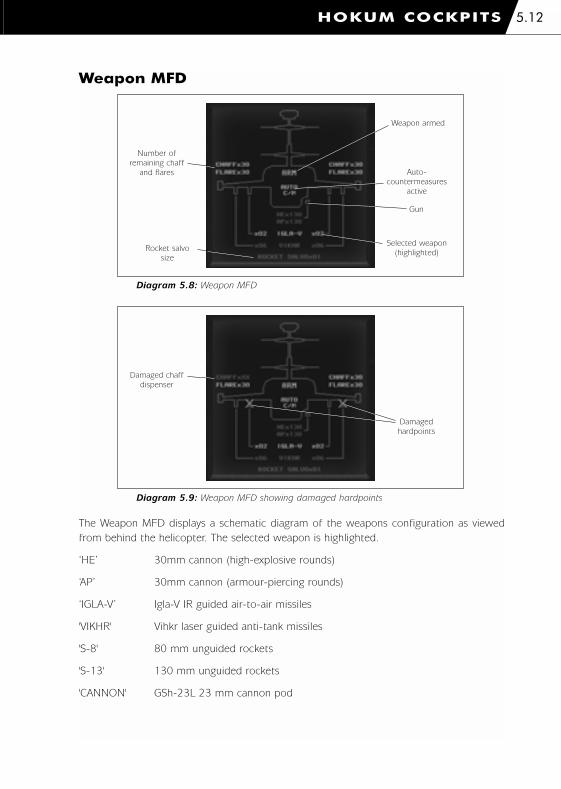
Weapon MFD
The Weapon MFD displays a schematic diagram of the weapons configuration as viewed
from behind the helicopter. The selected weapon is highlighted.
‘HE’ 30mm cannon (high-explosive rounds)
‘AP’ 30mm cannon (armour-piercing rounds)
‘IGLA-V’ Igla-V IR guided air-to-air missiles
'VIKHR' Vihkr laser guided anti-tank missiles
'S-8' 80 mm unguided rockets
'S-13' 130 mm unguided rockets
'CANNON' GSh-23L 23 mm cannon pod
HOKUM COCKPITS 5.12
Diagram 5.8: Weapon MFD
Number of
remaining chaff
and flares
Rocket salvo
size
Weapon armed
Gun
Auto-
countermeasures
active
Selected weapon
(highlighted)
Diagram 5.9: Weapon MFD showing damaged hardpoints
Damaged chaff
dispenser
Damaged
hardpoints
1036 EE-CH Manual - Chap 5 23/3/00 12:41 pm Page 5.12

System MFD
The System MFD displays the status of important helicopter components.
Engine MFD
The Engine MFD page displays values for both engines and also monitors the fuel level.
‘1’ Refers to the port (left) engine
‘2’ Refers to the starboard (right) engine
‘Np’ Engine RPM
‘Nr’ Rotor shaft RPM
‘TGT’ Temperature
The fuels weight is measured in kilogrammes.
HOKUM COCKPITS5.13
Diagram 5.10: System MFD
Diagram 5.11: Engine MFD
1036 EE-CH Manual - Chap 5 23/3/00 12:41 pm Page 5.13
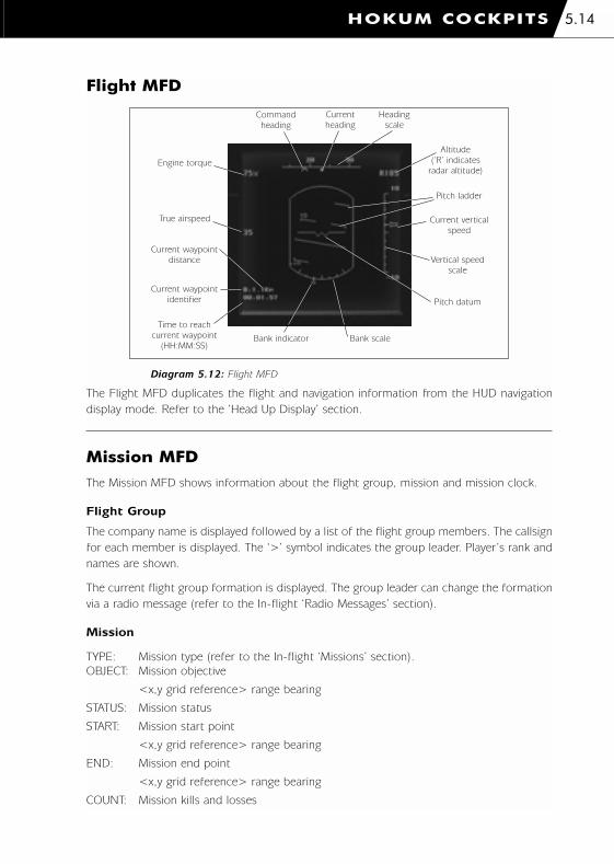
Flight MFD
The Flight MFD duplicates the flight and navigation information from the HUD navigation
display mode. Refer to the ‘Head Up Display’ section.
Mission MFD
The Mission MFD shows information about the flight group, mission and mission clock.
Flight Group
The company name is displayed followed by a list of the flight group members. The callsign
for each member is displayed. The ‘>’ symbol indicates the group leader. Player’s rank and
names are shown.
The current flight group formation is displayed. The group leader can change the formation
via a radio message (refer to the In-flight ‘Radio Messages’ section).
Mission
TYPE: Mission type (refer to the In-flight ‘Missions’ section).
OBJECT: Mission objective
<x,y grid reference> range bearing
STATUS: Mission status
START: Mission start point
<x,y grid reference> range bearing
END: Mission end point
<x,y grid reference> range bearing
COUNT: Mission kills and losses
HOKUM COCKPITS 5.14
Diagram 5.12: Flight MFD
Current waypoint
distance
Current waypoint
identifier
Time to reach
current waypoint
(HH:MM:SS)
Command
heading
Current
heading
Heading
scale
Bank indicator Bank scale
Engine torque
True airspeed
Pitch ladder
Altitude
(‘R’ indicates
radar altitude)
Current vertical
speed
Vertical speed
scale
Pitch datum
1036 EE-CH Manual - Chap 5 23/3/00 12:42 pm Page 5.14

TIME: MT=HH:MM:SS elapsed mission time
MD=HH:MM:SS estimated mission duration
Mission Clock
The mission clock indicates the time of day.
Head Up Display (HUD)
The head up display (HUD) is used to display primary flight and navigation information. In
combat modes the HUD is used in conjunction with the helmet-mounted sight (HMS) to
display targeting information.
The helmet-mounted sight is activated when either a weapon or target acquisition system
is selected. To return to the HUD navigation mode either make the weapons safe or switch
off the target acquisition system.
HOKUM COCKPITS5.15
Diagram 5.14: HUD in navigation mode
Bank scale
HUD centre
datum
Command
headingHeading scale Current heading
Current waypoint identifier Current waypoint distance
True airspeed
Engine torque
Angle of pitch
Altitude
(‘R’ indicates
radar altitude)
Vertical speed
scale
Vertical speed
indicator
Pitch datum
Diagram 5.13: Mission MFD
1036 EE-CH Manual - Chap 5 23/3/00 12:42 pm Page 5.15

HOKUM COCKPITS 5.16
The HUD display colour can be cycled to make it easier to read when the outside conditions
change.
K Select next HUD colour
m+ K Select previous HUD colour
Head Up Display In Navigation Mode
The Co-pilot/Gunner (CP/G) can assist you to identify targets. There are 3 levels of
assistance; ‘novice, ‘realistic’ and ‘off’. This is selected in the ‘Game Options’ menu.
HUD Centre Datum
Indicates the centre of the display.
Heading Scale and Command Heading
The heading scale is calibrated every 30 degrees. The command heading indicates the
direction to the next waypoint.
Angle of Pitch
The horizontal line indicates the direction of the horizon and the digital readout shows
the pitch angle.
Helicopter pitched up Horizontal line is below the HUD centre datum
Helicopter pitched down Horizontal line is above the HUD centre datum
Aircraft Datum and Bank Scale
The aircraft datum shows the orientation of the helicopter relative to the horizon. The
bank angle is indicated by the bank scale.
True Airspeed
True airspeed in km/h.
Altitude
Altitude in metres. Below 500m the readout is prefixed with an 'R' and shows radar
altitude (height above ground) and above 500m the readout shows barometric altitude
(height above sea level).
Vertical Speed Scale and Current Vertical Speed
The full scale deflection of the vertical speed scale is +/-10 metres. The current vertical
speed is indicated by the arrow.
Current Waypoint Identifier
The identifier for the current waypoint as shown on the waypoint route on the map
screen.
1036 EE-CH Manual - Chap 5 23/3/00 12:42 pm Page 5.16

Current Waypoint Distance
The distance to the current waypoint in kilometres.
Head Up Display/Helmet-Mounted Sight In Combat Mode
See the 'Acquiring Targets' and 'Weapons' sections.
Bob-up Overlay
The bob-up overlay is useful for 'station-keeping' during bob-up or bob-sideways
manoeuvres.
The symbology comprises an octagonal 'hover position' box, a bob-up command heading
and a velocity vector.
The HIDSS display represents a 200m x 200m overhead view around the original bob-up
position and the octagonal hover position box represents the helicopters rotor blades. As
the helicopter drifts from the bob-up position so the hover position box will drift from the
display centre. To keep 'on-station' fly towards the hover position box. The velocity vector
will assist you to do this. The velocity vector is calibrated up to 20 km/h.
The bob-up command heading appears on the heading strip and records the heading when
the bob-up overlay was engaged.
The bob-up overlay can be engaged with the display in either navigation or combat modes.
The bob-up overlay will disengage automatically if the helicopter drifts more than 500
metres from the original bob-up position.
HOKUM COCKPITS5.17
Diagram 5.15: Bob-up overlay
Bob-up command
heading
Velocity vector (to
keep ‘on-station’ –
fly towards the
hoverthe hover
position box)
Hover position
box
1036 EE-CH Manual - Chap 5 23/3/00 12:42 pm Page 5.17

Acquiring Targets
The Hokum has 3 target acquisition systems:-
1. a mast-mounted millimetric radar which can be used to scan for ground targets or
airborne targets
2. an Electro-Optical System (EOS) with Forward-Looking Infra-Red (FLIR) and Low Light
Level TV (LLLTV) channels plus a laser designator/range-finder. A ventrally mounted
periscope provides direct view optics
3. a helmet-mounted sight (HMS).
All three systems are integrated and a target acquired with one system may be passed to
another system as long as it falls within the targeting restraints of that system. Any target
which has been acquired is kept on a target list and all of the target acquisition systems are
able to cycle through this list.
Novice and Realistic Avionics
There is an option to select either ‘Novice’ or ‘Realistic’ avionics. This is selected in the
Options Screen ‘Realism’ menu.
Novice
The Novice avionics option simplifies the target acquisition systems. With this option
selected only the HMS system is available and this is automatically engaged whenever
you arm a weapon.
The performance of the HMS is exaggerated in this mode and you will never get a HUD
or HMS failure.
Realistic
The Realistic avionics option allows use of all the target acquisition systems as
described below.
HOKUM COCKPITS 5.18
Insert Home Page Up
Delete End Page Down
Air radar HMS Ground radar
FLIR LLLTV Periscope
Radar
Select Target Acquisition System
EOS
Diagram 5.16: Select target acquisition system
1036 EE-CH Manual - Chap 5 23/3/00 12:42 pm Page 5.18

CP/G Assistance: Target ID
The Co-pilot/Gunner (CP/G) can assist you to identify targets. There are 3 levels
of assistance; 'Novice', 'Realistic' and 'Off'. This is selected in the Options Screen
‘Realism’ menu.
Novice
The CP/G identifies the target immediately and reports them using simplistic names
such as ‘Enemy Tank’ and ‘Allied Aircraft’.
Realistic
The CP/G attempts to make a visual identification (using the EOS where possible). It
may take the CP/G a few moments to make the identification depending on the target
range and adverse weather conditions. During this time the message ‘CP/G
IDENTIFYING...’ is displayed instead of the target name. If there is no line of sight to
the target then no identification can be made. If you have selected an inappropriate EOS
system (you cannot use FLIR in heavy rain or LLLTV/Periscope at night) the message
‘LOW LIGHT’ is displayed in place of the target name. In this case select a more suitable
system. Once the identification is made the NATO reporting name is given for the target
and you must decide if it is an allied or enemy target.
Off
The CP/G gives you no help whatsoever. Once a target has been selected then use the
EOS systems to make the identification yourself. The 'Recognition Guide' will assist you
in spotting key recognition features.
Mast-Mounted Radar
The mast-mounted radar scans for targets and a symbolic image of the returns is shown on
the MFD display. The radar can only acquire targets to which it has line of sight (LOS). If an
acquired target masks behind buildings or terrain features the radar will still display the
target but the target category symbol will change. If the target was moving the radar will
attempt to interpolate the target's new position. Target symbols are displayed using two
different colours for clarity.
Target Categories LOS No LOS
Wheeled vehicle
Tracked vehicle
Air defence unit
Aircraft
Helicopter
Ship
Structure
HOKUM COCKPITS5.19
1036 EE-CH Manual - Chap 5 23/3/00 12:42 pm Page 5.19

Using radar will alert enemy targets of your presence and may attract hostile fire. Ensure
that you switch the radar off when you have finished using it!
Ground Radar
The ground radar can acquire battlefield targets and low slow flying helicopters. It can
categorise targets but cannot differentiate between allied and enemy. The ground radar
sweep is limited to a 90 degree arc ahead of the helicopter.
The ground radar shows cities and other built up areas as 'radar clutter'. It is only possible
to target certain strategic and tactical structures such as bridges and hardened aircraft
shelters.
HOKUM COCKPITS 5.20
Diagram 5.17: Ground radar display
Target locked
Target identity
(see CP/G
assistance)
EOS field of
view marker
EOS field of
regard box
Current heading Heading scale
MFD ‘Focus’ light
Target priority
Auto-target
engaged
Maximum
scan limitsScan limits
Radar clutter
Radar range
Selected target
Scan position
No line of sight
to target
Target range
Diagram 5.18: Ground radar controls
Num Lock
7
/ -
8
*
9
4 5 6
1 2 3
0 Del Enter
+
Activatesingle radarsweep
Single/continuousradar sweep
+ Scan size
Scan centre Scan rightScan left
– Scan size – Target priority
Auto-target
> Target
< Target (shift)
Switch off (ctrl)
Lock/unlocktarget
+ Range+ Target priority
– Range
Target Acquisition System Controls
+ = Increase – = Decrease> = Select Next< = Select Previous
1036 EE-CH Manual - Chap 5 23/3/00 12:42 pm Page 5.20

At the bottom of the ground radar display is the EOS field of view box and the field of
regard marker. As you cycle through the targets you will see the CP/G moving the field of
regard marker on to the target. In realistic CP/G Assistance mode the CP/G cannot identify
the target until the marker is on the target. Therefore if you are flying erratically the CP/G
will be unable to make an identification.
Range
Select ground radar range (1, 2, 4 or 6Km).
Scan size
Adjust the radar scan arc size. Minimising the arc size will reduce your visibility to enemy
targets and will increase the scan rate.
Scan direction
Adjust the radar scan direction left or right of centre.
Scan centre
Centre the radar scan.
Single/continuous radar sweep
Toggle between single sweep and continuous sweep.
Activate single radar sweep
Activate radar sweep in single sweep mode. Use single sweep mode to reduce your
visibility to enemy targets.
Target priority
Adjust the target priority (ALL, LOW, MEDIUM or HIGH) to declutter the radar. The
ground radar priority for each target is given in the 'Recognition Guide'. Generally any
target which can fire at the helicopter is high priority, other armour and battlefield
targets are medium priority and soft targets are low priority.
Next/previous target
Cycle forwards or backwards through the targets.
Auto-target
Toggle auto-target mode. In auto-target mode the ground radar automatically assesses
the highest threat target. This will only select targets of the selected priority.
Lock/unlock target
Lock the current target to prevent the auto-target system from selecting another target.
Switch off
Switch the ground radar off.
MFD 'focus' Light
The focus light indicates that this MFD page is being used by the selected target
acquisition system.
HOKUM COCKPITS5.21
1036 EE-CH Manual - Chap 5 23/3/00 12:42 pm Page 5.21

HOKUM COCKPITS 5.22
Air Radar
The air radar can acquire airborne targets. It can categorise targets and identify between
allied and enemy. The air radar can sweep through 360 degrees.
Air radar contacts will ‘timeout’ unless they are re-swept.
Diagram 5.19: Air radar display
Scan centre
Target locked
Target identity (see CP/G assistance)
Enemy or all targets
MFD ‘Focus’ light
Auto-target
engaged
Scan position
Scan limits
Radar range
Selected target
Target range
Num Lock
7
/ -
8
*
9
4 5 6
1 2 3
0 Del Enter
+
Activatesingle radarsweep
Single/continuousradar sweep
+ Scan size
Scan centre Scan rightScan left
– Scan size Auto-target
> Target
< Target (shift)
Switch off (ctrl)
Lock/unlocktarget
+ Range Display alliedaircraft
– Range
Target Acquisition System Controls
+ = Increase – = Decrease> = Select Next< = Select Previous
Diagram 5.20: Air radar controls
1036 EE-CH Manual - Chap 5 23/3/00 12:42 pm Page 5.22

HOKUM COCKPITS5.23
Range
Select ground radar range (1, 2, 4 or 6Km).
Scan size
Adjust the radar scan arc size. Minimising the arc size will reduce your visibility to enemy
targets and will increase the scan rate.
Scan direction
Adjust the radar scan direction left or right of centre.
Scan centre
Centre the radar scan.
Single/continuous radar sweep
Toggle between single sweep and continuos sweep.
Activate single radar sweep
Activate radar sweep in single sweep mode. Use single sweep mode to reduce your
visibility to enemy targets.
Display allied aircraft
Toggle display ALL aircraft targets or ENEMY targets only.
Next/previous target
Cycle forwards or backwards through the targets.
Auto-target
Toggle auto-target mode. In auto-target mode the air radar automatically assesses the
highest threat target.
Lock/unlock target
Lock the current target to prevent the auto-target system from selecting another target.
Switch off
Switch the air radar off.
MFD 'focus' Light
The focus light indicates that this MFD page is being used by the selected target
acquisition system.
1036 EE-CH Manual - Chap 5 23/3/00 12:42 pm Page 5.23

HOKUM COCKPITS 5.24
Diagram 5.22: HMS controls
Num Lock
7
/ -
8
*
9
4 5 6
1 2 3
0 Del Enter
+
Pan up
Pan centre Pan rightPan left
Pan down
> Target
< Target (shift)
Switch off (ctrl)
Lock/unlocktarget
+ Zoom
– Zoom
Target Acquisition System Controls
+ = Increase – = Decrease> = Select Next< = Select Previous
Electro-Optical System (EOS)
The electro-optical system comprises 3 components; a roof mounted ‘Samshit-F’
(Boxwood) FLIR/TV/laser system, a ventrally mounted periscope for direct view optics and
a chin mounted ‘Shkval-V’ (Gale) laser targeting and ranging system.
All 3 systems are slaved together and can move +/-110 degrees in azimuth (left or right)
and from +10 to -30 degrees in elevation (up or down). The image from the EOS is
displayed in an MFD.
Diagram 5.21: EOS display
EOS elevation
scale
Target locked
Target identity
(see CP/G assistance)
EOS boresight datum
EOS azimuth
scale
EOS azimuth
indicator
EOS azimuth heading
(not helicopter heading)
MFD ‘Focus’ light
Sensor type
(FLIR, LLLTV
or SCOPE
EOS elevation
indicator
Target
Target indicator
range
Field of view
EOS gates
Target range
scale (0 top,
5km bottom)
Target range
1036 EE-CH Manual - Chap 5 23/3/00 12:42 pm Page 5.24
HOKUM COCKPITS5.25
The EOS is used to locate, identify and designate targets. If you have selected no CP/G
assistance then you can use the EOS to identify targets before firing. Using the EOS is more
stealthy than using the radar as enemy targets are less likely to know that they are being
targeted.
To locate targets select the widest field of view available and slew the EOS in the direction
of the area of interest. Targets are brighter than the surrounding terrain. When you have
located a target, zoom in by reducing the field of view. When the EOS is aimed directly
towards the target the EOS gates appear and you can lock the target to keep it centred in
the display and make an identification. The EOS is especially useful for finding enemy
armour lurking in the tree-lines.
It is very difficult to use the EOS system when the helicopter is moving. You are
recommended to use this system when the helicopter is in a steady hover. Use the auto-
hover facility H.
If the light conditions are inappropriate for the selected sensor then a "LOW LIGHT" appears
on the EOS display.
Forward-Looking Infra-Red (FLIR)
The FLIR has 3 fields of view; wide, medium and narrow. The FLIR is ineffective in
adverse weather conditions.
Low Light Level TV (LLLTV)
The LLLTV only has a narrow field of view. The LLLTV is ineffective at night.
Periscope
The periscope has 2 fields of view; medium and narrow. The periscope is ineffective
at night.
Zoom
Select EOS field of view (WIDE, MEDIUM or NARROW).
Pan
Pan the EOS left, right, up and down. On an external view of the Hokum you can see
the EOS units move as you steer them.
Pan Centre
Centre the EOS pan.
Next/previous target
Cycle forwards or backwards through the targets.
Lock/unlock target
Lock the current target to prevent the auto-target system from selecting another target.
1036 EE-CH Manual - Chap 5 23/3/00 12:42 pm Page 5.25

HOKUM COCKPITS 5.26
Switch off
Switch the EOS off.
MFD 'focus' Light
The focus light indicates that this MFD page is being used by the selected target
acquisition system.
Helmet Mounted Sight (HMS)
The helmet-mounted sight enables the pilot to acquire targets simply by looking at them.
Effectively the radar and EOS are slaved to the HMS. At night-time Night Vision Goggles
(NVG) must be used. To activate night vision goggles press the N key.
The HMS display moves with your head and remains in the centre of the screen. You can
pan your view using the virtual cockpit keys. The functionality of these keys is duplicated on
to the numeric keypad arrow keys when HMS mode is selected.
To find targets with the HMS first select the HMS mode _ and make sure that you have a
weapon selected i. The HMS will boresight targets near to the display datum. When a
target is seen the target marker will appear.
You can ‘padlock’ the target by pressing either l+ j or 1. Press either l+j or
0 to unpadlock the target.
Diagram 5.23: HMS display – weapons are covered in more detail in the
Weapons section
Maximum range
of scale (km)
Weapon range
scale
Target range
indicator
Minimum range
of weapons
Target marker
Maximum range of weapon HMS centre datum
Sensor type
Target lock type
Target locked
Target identy
(see CP/G assistance)
Number of weapons
remaining
Weapon type
1036 EE-CH Manual - Chap 5 23/3/00 12:42 pm Page 5.26

HOKUM COCKPITS5.27
The weapon range scale indicates the minimum and maximum ranges of the selected
weapon and the range to the current target. The maximum range of the scale changes
according to the selected weapon and the range is shown as a digital readout in kilometres.
The weapon type indicates the selected weapon:-
‘Gun(HE)’ 30mm cannon (high-explosive rounds)
‘Gun(AP)’ 30mm cannon (armour piercing rounds)
‘Igla-V’ Igla-V IR guided air-to-air missiles
‘Vikhr’ Vikhr laser guided anti-tank missiles
‘S-8’ 80 mm unguided rockets
‘S-13’ 130 mm unguided rockets
‘GSh-23L’ GSh-23L 23mm cannon pods
The sensor type indicates the active target acquisition system:-
‘GND RDR’ Ground radar
‘AIR RDR’ Air radar
‘FLIR’ Forward-Looking Infra-Red
‘LLLTV’ Low Light Level TV
‘SCOPE’ Periscope
‘HMS’ Helmet-Mounted Sight
The target lock type indicates if the weapon has a valid lock else the reason for lock failure:-
Target markerwith invalid lock
Target market with valid lock
Target marker with central dot indicates an unguidedweapon is being usedagainst a ground target
When targets are in rangeof the turret gun or cannonpods the target markerswitches to a gun pipperwhich unwinds counter-clockwise as the targetdistance closes
Diagram 5.24: HMS display target marker
1036 EE-CH Manual - Chap 5 23/3/00 12:42 pm Page 5.27

HOKUM COCKPITS 5.28
‘NO ACQUIRE’ No target acquisition system is active
‘NO WEAPON’ No weapon is selected
‘NO TARGET’ No target has been designated
‘INVALID TARGET’ The target is unsuitable for the weapon
‘SEEKER LIMIT’ The target exceeds the weapon seeker limit
‘NO LOS’ No line of sight to the target
‘MIN RANGE’ The target is too near
‘MAX RANGE’ The target is too far
‘VALID LOCK’ The lock is good
Pan
Pan the HMS left, right up and down (use with g to pan the virtual cockpit view).
Next/previous target
Cycle forwards or backwards through the targets.
Lock/unlock target
Lock the current target to prevent the HMS from selecting another target.
Switch off
Switch the HMS target acquisition mode off.
Diagram 5.25: HMS controls
Num Lock
7
/ -
8
*
9
4 5 6
1 2 3
0 Del Enter
+
Pan up (alt)
Pan right(alt)
Pan left(alt)
Pan down
(alt)
> Target
< Target (shift)
Switch off (ctrl)
Lock/unlocktarget
Target Acquisition System Controls
+ = Increase – = Decrease> = Select Next< = Select Previous
1036 EE-CH Manual - Chap 5 23/3/00 12:42 pm Page 5.28

HOKUM COCKPITS5.29
Weapons
The Hokum is a heavily armed attack helicopter able to engage and destroy armoured and
unarmoured battlefield targets and airborne targets.
The Hokum has four hardpoints two on each stub wing and can carry many weapons mixes
depending on the mission requirements.
Selecting a weapon automatically switches the head-up display to combat mode and
activates the hemlet-mounted sight display. Making the weapons safe returns the head-up
display to navigation mode and switches the helmet-mounted sight off.
i Select next weapon
m+ i Select previous weapon
l+ i Weapons safe
To fire a weapon press the n. If the weapon fails to launch check the lock failure status
on the helmet mounted sight display.
30mm Cannon
The Hokum has a powerful 30mm 2A42 cannon mounted on the right (starboard) side of
the fuselage. The cannon is fed selectively from two containers allowing a choice of either
230 high-explosive rounds or 240 armour-piercing rounds.
The cannon automatically tracks the selected target and can be rotated from –2.5 to 9.0
degrees in azimuth (left or right) and from +13 to -40 degrees in elevation (up or down).
The cannon can be used against ground or air targets. Armour-piercing rounds are effective
against armoured battlefield targets and high-explosive rounds are effective against soft
ground targets and aircraft.
Type 30 mm cannon
Rate of fire 300 rounds per minute
Maximum range 2,000 metres
Muzzle velocity 1,000 metres per second
Weight 1 Kg
1036 EE-CH Manual - Chap 5 23/3/00 12:42 pm Page 5.29

HOKUM COCKPITS 5.30
Diagram 5.27: HMS display for turret gun showing out of range ground target
Diagram 5.28: HMS display for turret gun showing valid air target
Diagram 5.26: HMS display for turret gun showing valid ground target
Target range is
beyond the
maximum range
of the turret gun
Standard target
marker without
valid lock indication
Aiming point of
gun to intercept
the air target
Target within
min/max range
limits
Gun pipper
unwinds counter-
clockwise as target
range decreases
1036 EE-CH Manual - Chap 5 23/3/00 12:42 pm Page 5.30

HOKUM COCKPITS5.31
Igla-V
The Hokum carries Igla-V short-range air-to-air guided missiles. They are mounted in pairs
so a maximum of 8 missiles can be carried.
The Igla-V is a heat seeking missile and is effective against airborne targets. If a ground
target is selected then ‘INVALID TARGET’ is displayed on the HMS display.
Enemy targets will use flares and IR jammers to distract this missile.
Type Short-range air-to-air
Guidance Infra-red homing (fire-and-forget)
Maximum range 5,200 metres
Cruise speed Mach 2.5
Seeker field of view 60 degrees
Weight 18.2 Kg
Steering the HMS centre datum towards the computed intercept point will reduce the
amount of manoeuvering that the missile will have to do in flight and increase the kill
probability.
Diagram 5.29: HMS display for Igla-V showing valid air target
Computed intercept
point of weapon
with target
Target market
indicating
valid lock
1036 EE-CH Manual - Chap 5 23/3/00 12:42 pm Page 5.31

Vikhr
The Hokum carries Vikhr (Whirlwind) short-range anti-tank guided missiles. They are
mounted in racks of 6 but can only be fitted to the outer hardpoints so a maximum of 12
missiles can carried.
The Vihkr uses laser beam riding guidance and the target must remain in line of sight of the
helicopter throughout the missiles flight time. The missile flight time (in seconds) is
displayed on the HMS. If multiple weapons are fired then the flight time of the most
recently launched missile is displayed.
The Vikhr is effective against armoured battlefield targets but may also be used against slow
moving airborne targets.
Type Short-range anti-tank guided missile (ATGM)
Guidance Laser beam riding
Maximum range 6,000 metres
Cruise speed Mach 1.1
Seeker field of view 50 degrees
Weight 45.0 Kg
HOKUM COCKPITS 5.32
Diagram 5.30: HMS display for Vikhr showing valid ground target
Missile flight
time to impact
(seconds)
Target marker
indicating
valid lock
1036 EE-CH Manual - Chap 5 23/3/00 12:42 pm Page 5.32

HOKUM COCKPITS5.33
Unguided Rockets
The Hokum carries 80 mm (S-8) and 130 mm (S-13) folding-fin aerial rockets (FFARs).
These rockets are unguided so it is necessary to boresight the target by steering the
helicopter towards it. Use the forward cockpit view o.
Rockets can be fired in salvos to increase the damage area footprint.
S Increase salvo size
m+ S Decrease salvo size
S-8
The S-8 rockets are mounted in pods of 20 giving a maximum capacity of 80. They are
effective against unarmoured battlefield targets, soft structures and slow moving aircraft.
[Please highlight ‘Type ...’ as on page 6.28 of the Apache Havoc manual]
Type Folding-fin aerial rocket
Maximum range 4,000 metres
Weight 11.3 Kg
S-13
The S-13 rockets are mounted in pods of 5 giving a maximum capacity of 20. They are effective
against unarmoured battlefield targets, hardened structures and slow moving aircraft.
Type Folding-fin aerial rocket
Maximum range 6,000 metres
Weight 68.0 Kg
Diagram 5.31: HMS display showing unguided rocket not lined up with
ground target
Rocket salvo size
Steer helicopter
boresight towards
the target
Target
Boresight
1036 EE-CH Manual - Chap 5 23/3/00 12:42 pm Page 5.33

HOKUM COCKPITS 5.34
Diagram 5.32: HMS display showing unguided rocket lined up with
ground target
Diagram 5.33: HMS display showing unguided rocket not lined up with
air target
Diagram 5.34: HMS display showing unguided rocket lined up with
air target
Target lined up
with boresight
Steer boresight
towards
the intercept point
Target marker
Computed
intercept point
Boresight
Boresight lined
up with intercept
point
Target marker
1036 EE-CH Manual - Chap 5 23/3/00 12:42 pm Page 5.34

Cannon Pods
The Hokum carries cannon pods each containing twin-barrelled GSh-23L 23 mm cannons.
Each pod contains 250 rounds of ammunition. The cannon pods are effective against soft
ground targets and aircraft.
The cannon pods are aligned with the helicopter body-axis and so it is necessary to steer
the helicopter towards the target. Use the forward cockpit view o.
Type Twin-barrelled 23 mm cannon
Rate of fire 1,000 rounds per minute
Maximum range 2,000 metres
Muzzle velocity 930 metres per second
Weight 0.2 Kg
HOKUM COCKPITS5.35
Diagram 5.35: HMS display showing cannon pods lined up with ground target
Gun pipper lined
up with boresight
Target
Boresight
1036 EE-CH Manual - Chap 5 23/3/00 12:42 pm Page 5.35

HOKUM COCKPITS 5.36
Countermeasures
When the TWD display indicates a radar or infra-red threat then the following
countermeasures may be used to increase survivability.
Radar Jammer
The radar jammer is used to fool enemy radar of the helicopter's position by creating
spurious targets.
J Radar jammer on/off
IR Jammer
The IR jammer pumps out intense IR radiation to confuse the seeker head of an
incoming IR missile to break lock.
I IR jammer on/off
Chaff
Chaff comprises millions of strips of aluminised Mylar film which when released
generate a cloud of radar signature to fool incoming radar guided missiles.
C Release chaff cartridge
Flares
Flares are hot pyrotechnic cartridges used to create false targets for incoming IR
missiles.
F Release flare cartridge
The disadvantage of electronic countermeasures (ECM) such as the radar and IR
jammers is that they unmask the helicopter and increase its visibility. They should be
used as required.
The disadvantage of chaff and flares is that they run out! The Hokum carries 60 of each.
Automatic Countermeasures
The Co-pilot/Gunner can assist you with operating the countermeasures.
This option is selected in the Options Screen ‘Realism’ menu (Co-pilot ECM) and can
also be changed in-flight.
l+ C Automatic countermeasures on/off
Night Vision Goggles (NVG)
The Hokum pilot has night vision goggles to aid flying at night.
N NVG on/off
1036 EE-CH Manual - Chap 5 23/3/00 12:42 pm Page 5.36

HOKUM COCKPITS5.37
Windshield Wipers
In wet weather conditions the windshield wipers should be used. There is an
intermittent wipe option for lighter rain.
Y Windshield wiper on/off
g+ Y Toggle intermittent wipe
Ejector Seats
The Hokum has the novel feature of being fitted with ejector seats. The eject sequence
begins by blasting off the main rotors and canopy doors. Shortly afterwards the crew
are ejected. The debris falling from the Hokum will damage, if not destroy, other aircraft
so avoid ejecting if flying in close formation!
g+ E Eject
1036 EE-CH Manual - Chap 5 23/3/00 12:42 pm Page 5.37

BASICS 1
6. GROUND SCHOOL
1036 EE-CH Manual - Chap 6 23/3/00 12:44 pm Page 1
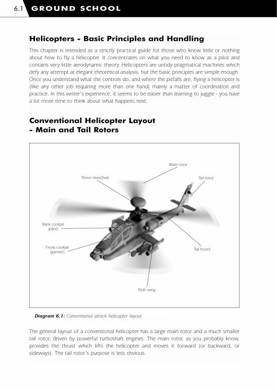
Helicopters - Basic Principles and Handling
This chapter is intended as a strictly practical guide for those who know little or nothing
about how to fly a helicopter. It concentrates on what you need to know as a pilot and
contains very little aerodynamic theory. Helicopters are untidy pragmatical machines which
defy any attempt at elegant theoretical analysis, but the basic principles are simple enough.
Once you understand what the controls do, and where the pitfalls are, flying a helicopter is
(like any other job requiring more than one hand) mainly a matter of coordination and
practice. In this writer’s experience, it seems to be easier than learning to juggle - you have
a lot more time to think about what happens next.
Conventional Helicopter Layout - Main and Tail Rotors
GROUND SCHOOL6.1
Rotor mast/hub
Main rotor
Tail rotor
Tail boom
Stub wing
Back cockpit(pilot)
Front cockpit(gunner)
Diagram 6.1: Conventional attack helicopter layout
The general layout of a conventional helicopter has a large main rotor and a much smaller
tail rotor, driven by powerful turboshaft engines. The main rotor, as you probably know,
provides the thrust which lifts the helicopter and moves it forward (or backward, or
sideways). The tail rotor’s purpose is less obvious.
1036 EE-CH Manual - Chap 6 23/3/00 12:44 pm Page 6.1

Imagine yourself sitting in a swivel chair, with your feet tucked up so the chair can spin
freely. Your arms are above your head, supporting the middle of a long heavy plank. The
plank is the helicopter’s main rotor and you are the engine. The swivel chair is the rest of
the helicopter, off the ground and free to pivot. Now start spinning the plank round and
round like a rotor. As you do this, you’ll find yourself spinning around in the opposite
direction to the rotor. The harder you spin the rotor, the faster you spin yourself - and in
this example, there’s nothing you can do to stop yourself spinning except put your feet on
the ground, which equates to landing the helicopter. This tendency for the engine to spin
the whole helicopter in the opposite direction to the main rotor can be called Main Rotor
Torque Effect.
The tail rotor solves this problem by creating a thrust in the opposite direction to the
main rotor torque effect. Its small size is compensated by the fact that it’s mounted at the
end of a long lever (the tail-boom) which magnifies its effect. Also, by changing the
amount of thrust the tail rotor produces you can pivot the whole helicopter on the spot, in
either direction.
How Rotors Work
A rotor is simply a set of long thin wings attached to a central hub. The wings are
more commonly called Rotor Blades, and when the rotor is spinning, the whole assembly
is often referred to as the Rotor Disc. Just as in an ordinary aircraft, the wings generate a
lift force when they are moved through the air. How much lift a wing generates is governed
by three factors:
1: The Density of the Air
The atmosphere is densest (and provides most lift) at sea level. As you climb above sea level
the density decreases and the wing produces less lift. Air temperature also affects density
– hot air is less dense than cold air, and gives less lift. ‘Hot and high’ is the worst
combination of conditions, and in practical terms this means you can lift less weight and
have less ‘performance’ available.
2: The Wing’s Speed Through the Air
The faster a wing moves through the air, the more lift it generates. In sophisticated modern
helicopters the rotors spin up to a set flying speed before take-off and hardly change speed
in flight, unless you demand more power than the engines can provide or something goes
wrong with the engines or the transmission system. You don’t control lift by changing the
rotor speed, so at first sight this factor seems irrelevant – and it is indeed irrelevant in
hovering or vertical flight. However, when the helicopter is moving forward at high speed
this factor becomes critically important, and determines the maximum safe flying speed –
and what happens when you exceed it [see page 6.19 – Retreating Blade Stall].
GROUND SCHOOL 6.2
1036 EE-CH Manual - Chap 6 23/3/00 12:44 pm Page 6.2

3: The Angle at Which the Wing Meets the Airflow
This is generally known as the Angle of Attack and up to a point which varies with the wing
design, the greater the angle of attack the more lift the wing generates (and the more
power is required to drive it through the air at a given speed). All of the helicopter’s main
flying controls work by changing the pitch angle of the main or tail rotor blades.
GROUND SCHOOL6.3
Rotormovingthis way
Relativeairflowthis way
Pitch angle/angle of attack
Diagram 6.2: Rotor pitch angle/angle of attack in still air
If the rotor were operating in still air, pitch angle and angle of attack would be identical, but
this situation exists only in the first few seconds as the rotor spins up [diagram 6.2]. Once
the rotor is spinning it sets up a constant air current (the rotor downwash) through the
rotor disc. This means that the effective angle of attack is less than the blade pitch angle –
though not much less because the rotor’s speed is generally much higher than the speed
of the air current down through the disc [diagram 6.3].
If there is an air current across the disc (as there is when you are hovering in a wind or
moving over the ground at any significant speed) this also changes the effective angle of
attack (and airspeed) of the rotor blades [diagram 6.4]. Blades advancing into the wind
have a higher angle of attack (and higher airspeed), and generate more lift than the
retreating blades. At the same time, the effect of the downwash air current is reduced
because you are constantly moving into undisturbed air.
The net result is that the rotor generates more lift altogether (‘Translational Lift’), and more
lift on the advancing than on the retreating side of the disc, so there is a slight tendency to
roll (a ‘rolling moment’) around the wind axis – an imaginary line through the centre of the
helicopter drawn in the direction of the airflow [diagram 6.5].
1036 EE-CH Manual - Chap 6 23/3/00 12:44 pm Page 6.3

GROUND SCHOOL 6.4
Airflow due to downwash
Actual directionof airflow
Airflow due torotor motion
Angle of attack(less than pitch angle)
Pitch angle
Diagram 6.3: Pitch angle/angle of attack with rotor downwash
Retreating side of disc
Advancing side of disc
Airflow due todownwash
Resulting airflow
Airflow due torotor motion
Angle of attack
A) Advancing blade
B) Retreating blade
Airflow due to wind orhorizontal flight
Blade pitch angle
Airflow due todownwashResulting airflow
Airflow due torotor motion
Reduced angle of attack
Airflow due to wind orhorizontal flight
Blade Pitch angle
Diagram 6.4: Pitch angle/angle of attack with airflow across rotor disc
1036 EE-CH Manual - Chap 6 23/3/00 12:44 pm Page 6.4
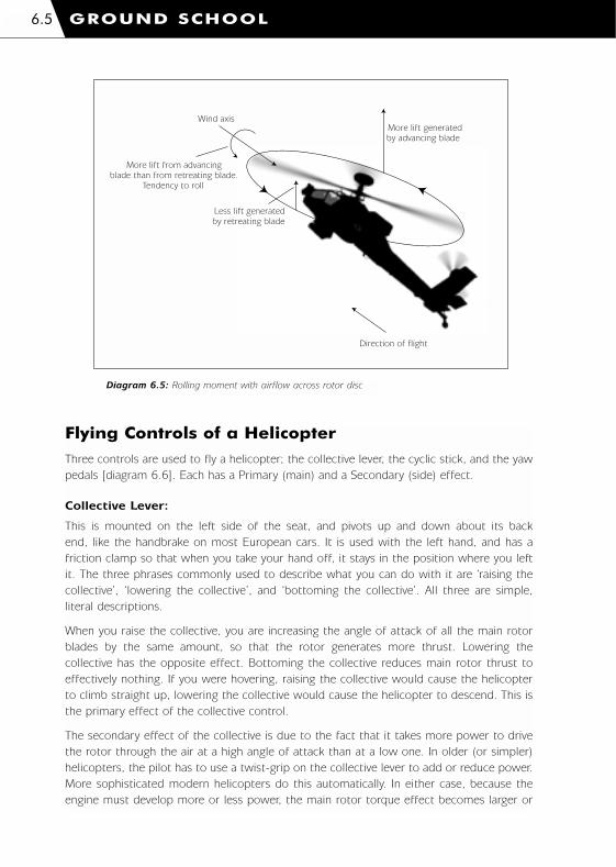
Wind axis
Direction of flight
More lift generatedby advancing blade
More lift from advancingblade than from retreating blade.
Tendency to roll
Less lift generatedby retreating blade
Flying Controls of a Helicopter
Three controls are used to fly a helicopter; the collective lever, the cyclic stick, and the yaw
pedals [diagram 6.6]. Each has a Primary (main) and a Secondary (side) effect.
Collective Lever:
This is mounted on the left side of the seat, and pivots up and down about its back
end, like the handbrake on most European cars. It is used with the left hand, and has a
friction clamp so that when you take your hand off, it stays in the position where you left
it. The three phrases commonly used to describe what you can do with it are ‘raising the
collective’, ‘lowering the collective’, and ‘bottoming the collective’. All three are simple,
literal descriptions.
When you raise the collective, you are increasing the angle of attack of all the main rotor
blades by the same amount, so that the rotor generates more thrust. Lowering the
collective has the opposite effect. Bottoming the collective reduces main rotor thrust to
effectively nothing. If you were hovering, raising the collective would cause the helicopter
to climb straight up, lowering the collective would cause the helicopter to descend. This is
the primary effect of the collective control.
The secondary effect of the collective is due to the fact that it takes more power to drive
the rotor through the air at a high angle of attack than at a low one. In older (or simpler)
helicopters, the pilot has to use a twist-grip on the collective lever to add or reduce power.
More sophisticated modern helicopters do this automatically. In either case, because the
engine must develop more or less power, the main rotor torque effect becomes larger or
GROUND SCHOOL6.5
Diagram 6.5: Rolling moment with airflow across rotor disc
1036 EE-CH Manual - Chap 6 23/3/00 12:44 pm Page 6.5

smaller and the whole helicopter tends to start rotating one way or the other. The yaw
pedals [see page 6.7 – Yaw Pedals] are used to counter this tendency.
Cyclic Stick:
The cyclic stick (commonly called ‘the cyclic’) is mounted centrally in front of the pilot’s
seat, with a pivot at the base which allows it to be tilted forward, backward and to either
side. It is normally held with the right hand, and spring-loaded to a more or less central,
upright position.
When you tilt the cyclic away from the upright position, each main rotor blade changes its
angle of attack as it moves around the hub. Over half the circle, the angle of attack is
greater than the level set by the collective, producing more lift, while over the other half it
is less, and less lift is generated. The maximum and minimum points are the same for all
blades, so the main rotor’s thrust is tilted in the same direction as the cyclic stick itself, the
helicopter itself tilts the same way, and starts to move over the ground in that same
direction.
Proper handling of the cyclic (especially at low speeds, or in the hover) demands a light
touch and intelligent anticipation or the helicopter will slide and wallow about in an
apparently endless series of overcorrections. A student pilot’s first attempts to hover on the
spot will usually have spectators gasping with laughter and alarm by turns – especially in
variable winds.
GROUND SCHOOL 6.6
Cyclic
Pedals
Collective
Diagram 6.6: Main flying controls
1036 EE-CH Manual - Chap 6 23/3/00 12:44 pm Page 6.6

Yaw Pedals:
The two yaw pedals (also called ‘torque pedals’ or just ‘pedals’) are mounted in the obvious
place for pedals, one at each end of a bar which pivots in the middle. Push one pedal
forward and the other moves back by the same amount. They operate on the tail rotor in
much the same way that the collective operates on the main rotor, by changing the pitch
(and hence the angle of attack) of all the blades at once, thus increasing and decreasing the
tail rotor’s thrust, or even reversing its direction. As described above, they are used to pivot
the helicopter on the spot (a ‘pedal turn’), and to keep the helicopter pointing in your
chosen direction when the collective is raised or lowered by compensating for the changing
strength of the main rotor torque effect.
Pushing on the left pedal turns the helicopter to the left, and vice versa for the right pedal.
In this respect they work like the rudder pedals of an aircraft – and in exactly the opposite
sense to a bike’s handlebars. This can confuse beginners, but practice will quickly sort you
out – and it seems to do no permanent harm to your ability to steer a bike.
Putting it all Together
Now that you’ve been told what each of the controls does by itself, it’s time to show
how they’re used together when actually flying a helicopter. We’ll look at the sequence of
actions required to take off, transition to forward flight, climb and dive, make gentle turns,
slow to a stop and land. Read through the exercise before trying it out for the first time. It
is worth emphasising that all your control movements (‘control inputs’) should be as
smooth and deliberate as possible. Sudden, violent control inputs are to be avoided. Make
sure that you know where to find airspeed, altitude and vertical velocity readouts on the
Head-Up Display (HUD).
1: Taking Off and Rising to the Hover
We’ll start with the helicopter sitting on the ground, engines running and rotor spun up to
flying speed, in calm conditions. In order to lift off we need to raise the collective slowly
and carefully, until we have just enough lift to raise the helicopter off the ground and start
climbing vertically. At the same time, we need to feed in some pedal. If we don’t do this,
then as soon as the weight comes off the wheels, we’ll start slewing round on the spot
because of the main rotor torque effect. This is one excellent reason for raising the
collective gently – the harder you yank on the collective, the bigger the torque effect.
GROUND SCHOOL6.7
1036 EE-CH Manual - Chap 6 23/3/00 12:44 pm Page 6.7
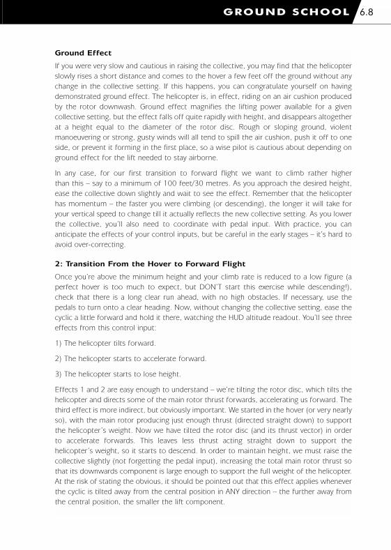
Ground Effect
If you were very slow and cautious in raising the collective, you may find that the helicopter
slowly rises a short distance and comes to the hover a few feet off the ground without any
change in the collective setting. If this happens, you can congratulate yourself on having
demonstrated ground effect. The helicopter is, in effect, riding on an air cushion produced
by the rotor downwash. Ground effect magnifies the lifting power available for a given
collective setting, but the effect falls off quite rapidly with height, and disappears altogether
at a height equal to the diameter of the rotor disc. Rough or sloping ground, violent
manoeuvering or strong, gusty winds will all tend to spill the air cushion, push it off to one
side, or prevent it forming in the first place, so a wise pilot is cautious about depending on
ground effect for the lift needed to stay airborne.
In any case, for our first transition to forward flight we want to climb rather higher
than this – say to a minimum of 100 feet/30 metres. As you approach the desired height,
ease the collective down slightly and wait to see the effect. Remember that the helicopter
has momentum – the faster you were climbing (or descending), the longer it will take for
your vertical speed to change till it actually reflects the new collective setting. As you lower
the collective, you’ll also need to coordinate with pedal input. With practice, you can
anticipate the effects of your control inputs, but be careful in the early stages – it’s hard to
avoid over-correcting.
2: Transition From the Hover to Forward Flight
Once you’re above the minimum height and your climb rate is reduced to a low figure (a
perfect hover is too much to expect, but DON’T start this exercise while descending!),
check that there is a long clear run ahead, with no high obstacles. If necessary, use the
pedals to turn onto a clear heading. Now, without changing the collective setting, ease the
cyclic a little forward and hold it there, watching the HUD altitude readout. You’ll see three
effects from this control input:
1) The helicopter tilts forward.
2) The helicopter starts to accelerate forward.
3) The helicopter starts to lose height.
Effects 1 and 2 are easy enough to understand – we’re tilting the rotor disc, which tilts the
helicopter and directs some of the main rotor thrust forwards, accelerating us forward. The
third effect is more indirect, but obviously important. We started in the hover (or very nearly
so), with the main rotor producing just enough thrust (directed straight down) to support
the helicopter’s weight. Now we have tilted the rotor disc (and its thrust vector) in order
to accelerate forwards. This leaves less thrust acting straight down to support the
helicopter’s weight, so it starts to descend. In order to maintain height, we must raise the
collective slightly (not forgetting the pedal input), increasing the total main rotor thrust so
that its downwards component is large enough to support the full weight of the helicopter.
At the risk of stating the obvious, it should be pointed out that this effect applies whenever
the cyclic is tilted away from the central position in ANY direction – the further away from
the central position, the smaller the lift component.
GROUND SCHOOL 6.8
1036 EE-CH Manual - Chap 6 23/3/00 12:44 pm Page 6.8

Translational Lift
As the helicopter gathers speed, you’ll find that you start gaining height again. This is due
to a phenomenon called Translational Lift, which is hard to explain simply, but is basically
due to the fact that the angle of the airflow passing through the main rotor has changed
due to the tilting of the rotor disc and the helicopter’s motion (translation) through the air.
This increases the effective angle of attack of the main rotor blades, producing more thrust.
Translational lift appears at quite low speeds, but disappears again with rising speed – and
its effects are felt whether the helicopter moves forwards, sideways or backwards.
3: Climbing and Diving
To gain height in a helicopter flying forwards, you can a) pull back on the cyclic, b) raise the
collective, or c) use both controls together or in sequence – this is what normally happens.
If you just pull back on the cyclic, the helicopter’s nose will rise and it will start to climb,
but it will also start to lose forward speed – you’re redirecting the main rotor thrust so that
you have more lift force and less horizontal thrust. Provided that the cyclic is still forward
of the central (hover) position, forward speed will stabilise at a lower figure than you
started with.
If you simply raise the collective (with pedal input) in forward flight, you’re increasing the
main rotor thrust without changing its angle, so you have more lift AND more thrust
available. The helicopter will climb and accelerate. If you want to climb without losing or
gaining speed, you need to pull back on the cyclic AND simultaneously raise the collective.
In a similar (though not identical) way, you can lose height using cyclic input or collective
input or both. If you push forward on the cyclic you will lose height and gain speed (more
horizontal thrust, less lift). If you lower the collective you will lose both height and speed
(less total thrust, so less horizontal thrust and less lift).
Once you appreciate the effects of the controls and have some experience in using them,
you can choose the right combination of cyclic and collective inputs to make the helicopter
do what you want, up to the limits of performance.
GROUND SCHOOL6.9
1036 EE-CH Manual - Chap 6 23/3/00 12:44 pm Page 6.9

GROUND SCHOOL 6.10
Rotor thrust Lift
Weight
Rotor thrust Lift component
WeightHelicopter motion
Rotor thrust Lift component
Helicopter motion
Thrust component
Thrust component
A)
B)
C)
Cyclic upright.No collective input.Lift equals weight.Helicopter hovers.
Cyclic tilted. No collective input. Lift less than weight.Helicopter descends.Thrust component startshorizontal acceleration.
Cyclic as in B). Collective raised.Lift equals weight. Helicopter accelerates horizontally without gaining or losing height.
Diagram 6.7: Lift and thrust components
1036 EE-CH Manual - Chap 6 23/3/00 12:44 pm Page 6.10

4: Turning in Forward Flight
When the helicopter is hovering or flying at low speed, if you want to turn you do it mainly
or exclusively with the pedals. At higher forward speeds, turning is accomplished by tilting
the cyclic left or right to bank the helicopter just like a fixed-wing aircraft, though there is
no need to use pedal inputs to coordinate the turn. If you fly sustained or steeply-banked
turns, however, you’ll need to either raise the collective (with pedal input) or ease back on
the cyclic, sacrificing some forward speed. If you do neither then you’ll lose height because
banking tilts the rotor disc (and thrust vector) further away from the vertical, trading off lift
for the sideways thrust component which causes the turn [diagram 6.7].
5: Slowing to the Hover from Forward Flight
This technique is called Flaring, and is essentially similar for all wing-borne flying machines,
though the helicopter variant is the most complex and demanding since it requires precisely
coordinated use of all three controls. The object of the exercise is to slow to a stop in the
minimum distance without losing or gaining height. Losing height can be unhealthy
for obvious reasons, while gaining height (and exposing yourself unnecessarily) is in
military terms ‘tactically unsound’ – a phrase normally used as a diplomatic substitute for
‘lethally stupid’.
Throughout this manoeuvre you should constantly scan the HUD altimeter/vertical velocity
indicator (to see and correct altitude changes) and the view forward (to crosscheck the
altimeter and keep yourself heading in a straight line).
You start the manoeuvre by pulling back on the cyclic to tilt the helicopter backwards – use
a moderate nose-up angle to start with, and experiment with steeper angles as you gain
experience and confidence. This directs the rotor thrust backwards, which will tend to slow
you down, but it also increases the rotor blades’ effective angle of attack, and therefore the
total thrust – which means that you’ll climb unless you simultaneously lower the collective.
As the helicopter slows, main rotor thrust diminishes (slowly raise the collective to
compensate), and as you approach the hover you’ll need to ease the cyclic forward again
to bring the helicopter level, simultaneously raising the collective to the hover setting.
[Diagram 6.8] shows the relationship between cyclic and collective movements for the
whole manoeuvre. Pedal is used as necessary to compensate for collective movement and
to keep the helicopter straight.
6: Landing Problems and Techniques
Though we’ve just gone through the Flare manoeuvre, with the emphasis on slowing to the
hover without gaining or losing height, this technique generally needs modifying to convert
it into a sensible approach to a landing. The reason for this is that unless you’re already
flying very low indeed, the flare will leave you hovering higher than you want to be for a
safe and sensible vertical descent to touchdown. The problem is mainly one of visibility, and
is particularly acute in combat helicopters.
Visibility Factors
In a combat helicopter with a classical crew arrangement (gunner in front of pilot, both on
GROUND SCHOOL6.11
1036 EE-CH Manual - Chap 6 23/3/00 12:44 pm Page 6.11
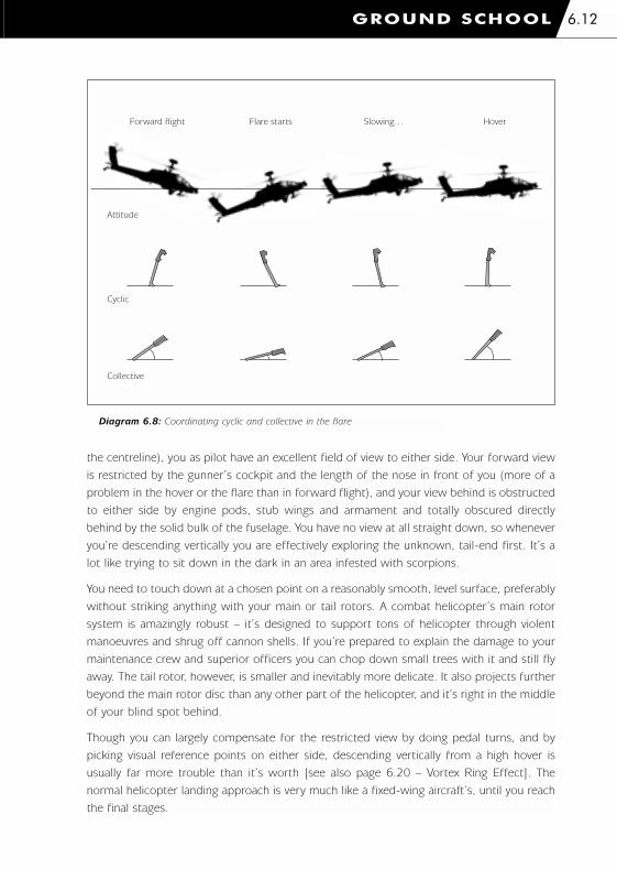
the centreline), you as pilot have an excellent field of view to either side. Your forward view
is restricted by the gunner’s cockpit and the length of the nose in front of you (more of a
problem in the hover or the flare than in forward flight), and your view behind is obstructed
to either side by engine pods, stub wings and armament and totally obscured directly
behind by the solid bulk of the fuselage. You have no view at all straight down, so whenever
you’re descending vertically you are effectively exploring the unknown, tail-end first. It’s a
lot like trying to sit down in the dark in an area infested with scorpions.
You need to touch down at a chosen point on a reasonably smooth, level surface, preferably
without striking anything with your main or tail rotors. A combat helicopter’s main rotor
system is amazingly robust – it’s designed to support tons of helicopter through violent
manoeuvres and shrug off cannon shells. If you’re prepared to explain the damage to your
maintenance crew and superior officers you can chop down small trees with it and still fly
away. The tail rotor, however, is smaller and inevitably more delicate. It also projects further
beyond the main rotor disc than any other part of the helicopter, and it’s right in the middle
of your blind spot behind.
Though you can largely compensate for the restricted view by doing pedal turns, and by
picking visual reference points on either side, descending vertically from a high hover is
usually far more trouble than it’s worth [see also page 6.20 – Vortex Ring Effect]. The
normal helicopter landing approach is very much like a fixed-wing aircraft’s, until you reach
the final stages.
GROUND SCHOOL 6.12
Forward flight Flare starts Slowing… Hover
Attitude
Cyclic
Collective
Diagram 6.8: Coordinating cyclic and collective in the flare
1036 EE-CH Manual - Chap 6 23/3/00 12:44 pm Page 6.12

Circuit Pattern
The obvious conclusion is that whenever you’re landing in an unfamiliar area with potential
hazards and obstructions you should always check it first. The standard technique for doing
this is to fly a ‘circuit’ [diagrams 6.9 and 6.10].
The first piece of information you need is the wind direction and if possible its strength and
gustiness. You may know this already, it may be provided for you by someone on the ground
with a radio (or a set of marker panels), or if not then you can usually observe it for yourself
by looking for drifting smoke, flags or other such clues.
The reason why wind direction is important is that you should try to land with your nose
pointing into the wind. While this is a nearly inviolable rule for fixed-wing aircraft because
it reduces speed over the ground and the length of the landing run, helicopter pilots have
more choice in the matter [see page 6.18 – Sideways]. Nevertheless, your life will be easier
if you can land facing into wind.
The wind direction (or the layout of the site) establishes the direction of your landing
approach, and the orientation of the circuit pattern. Use the downwind and base legs of the
circuit to inspect the landing area and reduce your height and speed. As you pass the
touchdown point on the downwind leg, look for visual reference points on either side which
you can use to locate yourself once the touchdown point has disappeared under your nose.
GROUND SCHOOL6.13
Wind direction
Visual references fortouchdown point
Downwind leg
Baseleg
Final approach
Diagram 6.9: Circuit pattern for a clear landing area
1036 EE-CH Manual - Chap 6 23/3/00 12:44 pm Page 6.13
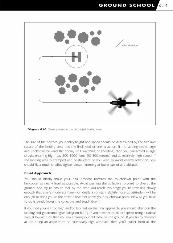
The size of the pattern, your entry height and speed should be determined by the size and
nature of the landing area, and the likelihood of enemy action. If the landing site is large
and unobstructed (and the enemy isn’t watching or shooting) then you can afford a large
circuit, entering high (say 500-1000 feet/150-300 metres) and at relatively high speed. If
the landing area is cramped and obstructed, or you wish to avoid enemy attention, you
should fly a much smaller, tighter circuit, entering at lower speed and altitude.
Final Approach
You should ideally make your final descent towards the touchdown point with the
helicopter as nearly level as possible. Avoid pushing the collective forward to dive at the
ground, and try to ensure that by the time you reach this stage you’re travelling slowly
enough that a very moderate flare – or ideally a constant slightly nose-up attitude – will be
enough to bring you to the hover a few feet above your touchdown point. Now all you have
to do is gently lower the collective and touch down.
If you find yourself too high and/or too fast on the final approach, you should abandon the
landing and go around again [diagram 6.11]. If you attempt to kill off speed using a radical
flare at low altitude then you risk striking your tail rotor on the ground. If you try to descend
at too steep an angle from an excessively high approach then you’ll suffer from all the
GROUND SCHOOL 6.14
Wind direction
Diagram 6.10: Circuit pattern for an obstructed landing area
1036 EE-CH Manual - Chap 6 23/3/00 12:44 pm Page 6.14

visibility problems we discussed earlier, plus running the risk of Vortex Ring Effect [diagram
2.14]. Just raise the collective to arrest your descent (or climb if there are obstacles to
clear), fly on over and past the touchdown point, and turn into another circuit – smaller,
lower and slower than the first. Keep it in mind that you’ll find it much easier to establish
the second circuit if you continue some way along the approach line past the touchdown
point before you turn.
We Don’t Need no Stinking Circuits!
Oh yes, you do. It’s not just a piece of textbook ritual. The procedure described above may
seem formal and longwinded but it really is useful. Not only does it give you the chance to
scout the landing area, but the sequence of legs and turns lets you judge and adjust your
speed and rate of descent relative to the touchdown point – and the turns can be used to
kill off a great deal of speed. A straight-in approach looks much simpler and is perfectly
practical for landing in the middle of a wide open airfield, but as soon as you have to deal
with obstructions and previously unseen landing sites, the circuit pattern is much safer,
usually faster, and saves a great deal of wear and tear on your nerves.
GROUND SCHOOL6.15
Overfly touchdown point,then enter second smaller circuit
First approachtoo high/too fast
Diagram 6.11: Going around again
1036 EE-CH Manual - Chap 6 23/3/00 12:44 pm Page 6.15

GROUND SCHOOL 6.16
The key to a successful circuit of any size is to select the correct combination of height and
lateral offset (between downwind and final legs). This can be done by learning to recognise
the angle, or range of angles, you see when you look down on the touchdown point from
the downwind leg. This skill, like any other, can only be acquired by means of practice.
Key point: opposite touchdown point on downwind leg
Learn to recognisethis angle
Diagram 6.12: Judging offset and height in the circuit
1036 EE-CH Manual - Chap 6 23/3/00 12:44 pm Page 6.16

GROUND SCHOOL6.17
Direction ofrelative wind
Turning forceexerted by tail fin
Thrust availablefrom tail rotor
Direction of flight
No lever armNo tail surface exposed
No turning force
Some tail surface exposedTurning force exists
More tail surface exposedMore turning force
If you fly backwards fasterthan your maximum controllablesideways speed, once thehelicopter turns past a certainangle, you cannot stop the turn
Lever arm
Lever arm
Diagram 6.13: Turning forces in backwards flight
1036 EE-CH Manual - Chap 6 23/3/00 12:44 pm Page 6.17

Sideways, Backwards and Crosswinds
If you have absorbed and understood the basic principles of helicopter flight it should be
obvious that you can fly the helicopter in any direction from the hover, without turning, by
tilting the cyclic the way you want to go. You can also hover on the spot in a wind blowing
from any direction by tilting the cyclic into the wind. There are, however, a few pitfalls which
should be pointed out.
Weather-Cocking
The helicopter’s tailboom is there for two main reasons. We’ve already mentioned that it
provides a convenient mounting point for the tail rotor, outside the worst of the main rotor
downwash, and at the end of a long lever arm. Those same factors also make it the best
place to mount a vertical fin (or fins) very like what you find at the tail end of most fixed-
wing aircraft, and serving exactly the same purpose; to provide automatic directional
stability in fast forward flight, just like the fletching of a dart or an arrow.
The tail fin works against you when you try to fly sideways or hover in a cross-wind,
generating a force which tends to turn the helicopter’s nose into the relative wind. The
whole helicopter acts like a weather-vane. To counter this effect you must use pedal inputs
– and the faster you fly (or the stronger the crosswind) the larger the input needed to
maintain heading. Eventually you’ll reach a point where the tail rotor simply cannot provide
any more thrust, and the nose will inexorably turn into the relative wind. This is one of the
main reasons why a helicopter’s maximum sideways speed is much lower than the
maximum forward speed – and a wise pilot will always try to avoid flight regimes which can
only be maintained by jamming any control hard against its stops.
Stability in Backwards Flight
Backwards flight is something that obviously needs to be done carefully – you can’t see
where you’re going, and you’re flying tail rotor first. There are less obvious problems which
affect you even if you have unlimited space for manoeuvre, or if you’re simply trying to
hover in a strong tail-wind. The explanation involves some basic physics, but the diagram
should help you grasp what’s going on.
The strength of the turning force generated by the tail fin depends mainly on three factors:
1) The speed of the relative wind.
2) How large a surface the tail fin presents to the relative wind.
3) The effective length of the tail fin’s lever-arm with respect to the relative wind and the
helicopter’s centre of mass, which we can assume will be more or less directly under the
main rotor hub.
Taking these factors in order; 1) more airspeed means more force. In fact, because the force
is proportional to the square of the airspeed, a little more speed means a lot more force.
2) When the tail is pointing straight into the wind, it is exposing the least possible area and
generating the least possible force. As the tail swings out across the wind, it presents more
and more surface area, generating more and more force. 3) When the tail is pointing
GROUND SCHOOL 6.18
1036 EE-CH Manual - Chap 6 23/3/00 12:44 pm Page 6.18

straight into the wind, it is in line with the centre-of-mass and there is no leverage. As the
tail swings out across the wind, the length of the lever-arm increases and so does the
turning force. Factors 2 and 3 both reach their maximum when the helicopter is broadside-
on to the wind, as it is when you’re flying sideways.
Because the tail fin exerts no turning effect when pointing straight into the relative wind (and
the helicopter’s fuselage is generating little or no more drag than it does when flying forwards)
it is possible to accelerate to much higher speeds in backwards than in sideways flight.
The catch comes when the tail turns out of line. The moment any turning force is
generated, it tends to turn the helicopter even further off the wind, generating even more
turning force, and so on in a vicious circle. At high speeds this happens so quickly that you
have very little time to correct the swing, and if you are moving faster than your maximum
stable sideways speed, once the swing goes beyond a certain point you don’t have enough
tail-rotor thrust to stop it anyway.
At this point you’ve lost control of the turn, which is almost exactly like a handbrake turn
or U-turn in a car. The helicopter swaps ends in an instant, the main rotor blades flap and
thrash madly, and if you’re lucky they don’t smash the cockpit canopy or chop off the tail
boom as the rotor disc tries to re-align itself with the suddenly and violently changing
attitude of the rotor mast.
It is possible (and even potentially tactically useful) to perform milder variants of this
manoeuvre under control, but work up to it cautiously. Approach it as you would approach
the problem of performing a backflip while whirling a sharp sword around your head.
Hazards and Emergencies:
Landing on Slopes
When necessary, it is entirely possible to land safely on a smooth moderate slope, but the
technique needs practice. Though at first sight it might seem natural to land facing up the
slope, the preferred direction is sideways, facing into the wind. If you don’t think the
helicopter will be stable standing across the slope, then the slope is too steep, and you
must find somewhere else.
Approach as normal, but slow your final descent so that you hover with your uphill wheel
just touching the ground. Now very gently lower the collective, and as the helicopter leans,
move the cyclic in the opposite direction so that the rotor disc remains horizontal. Once
both wheels are on the ground, carefully lower the collective to transfer the weight to the
wheels, keeping the rotor disc horizontal, to oppose the pull of gravity, rather than tilting it
to match the cross-slope.
Take-off can be accomplished by simply reversing the landing drill. The important things are
to keep the rotor disc horizontal and to use a very delicate touch on the collective when
the wheels are on the ground.
Retreating Blade Stall
We have already talked about the difference in lift developed by the advancing and
retreating blades of the main rotor in horizontal flight, which is due to the difference in their
GROUND SCHOOL6.19
1036 EE-CH Manual - Chap 6 23/3/00 12:44 pm Page 6.19

GROUND SCHOOL 6.20
Diagram 6.14: Vortex rings
effective airspeeds. Lift is directly and sensitively proportional to airspeed, but for any given
wing at any angle of attack there will be a critical speed below which lift suddenly collapses
– the wing stalls. For any reasonably powerful or streamlined helicopter, the maximum safe
airspeed is determined by the speed at which the retreating rotor blade starts to stall.
In this situation, you suddenly start to lose lift on the retreating blade side, and the
helicopter rolls towards it. Provided that you are not diving too steeply, you may be able to
reduce speed by lowering the collective and pulling back on the cyclic before you lose
control, but beware of violent panicky manoeuvres, which may stall more blade area or set
the blades flapping violently.
Like all aerodynamic effects, retreating blade stall is affected by air density and by
temperature. It will happen at lower speeds at higher altitudes and/or higher temperatures.
Vortex Ring Effect
The commonest visible example of a vortex ring (or ring vortex) is a smoke-ring. In fact they
are quite a widespread phenomenon, but like all flow patterns they are usually impossible
to see directly. All you need to start one is a stream with a more or less circular cross-
section (like your rotor downwash) which satisfies certain other conditions.
In a helicopter, you can unintentionally create a vortex ring around your main rotor if you
make a sustained high-speed descent vertically or at a steep angle. Once the ring has
A) Airflow pattern and motion of a vortex ring
B) Helicopter descending in vortex ring effect
1036 EE-CH Manual - Chap 6 23/3/00 12:44 pm Page 6.20

formed, it is surprisingly stable, and moves with you as you descend. The extra downwash
of the circulating vortex ring destroys most of the main rotor’s lift, and you cannot escape
by raising the collective – you will only pump energy into the ring’s circulation. You are
already descending too fast to escape downwards and outrun it. The only way out is to use
the cyclic to move laterally, because lateral movement disrupts the vortex, just as vertical
movement maintains it.
Coping with Reduced Power
If you lose an engine in a powerful twin-engined helicopter like the Comanche or the Hokum
you can still fly, land and take off, provided that you don’t try to lift heavy weights in hot
and high conditions or leap tall buildings at a single bound. The keys to achieving this are
translational lift and ground effect. Every time you raise the collective for more lift you put
more strain on the surviving engine, and the rotor speed may slow to dangerous levels.
Ground effect multiplies your main rotor lift and may let you hover with reduced power.
It also provides a convenient low-friction environment in which to accelerate to a speed
where translational lift can let you climb out of ground effect. When approaching for a
landing, or descending and decelerating for any other reason, let yourself gently down at a
shallow angle or a low speed, or both. The ground effect cushion is no deeper than your
main rotor diameter.
If you cannot even hover in ground effect, you may still be able to achieve a running
landing, if space is available. The approach is flown very like a low speed approach to a runway
in a fixed-wing aircraft. Just as in an aircraft, you round out your descent by pulling smoothly
back on the cyclic before you touch the ground so that you kiss it gently rather than crash into
it at an angle. At the same time you must avoid plunging your tail-rotor into the ground.
If you’re running out of horizontal speed but close to the ground you can probably afford
to raise the cyclic to slow the last seconds of descent. If you run out of forward speed and
rotor rpm at the same time, you’d better hope that you don’t have too far to fall.
Running takeoffs are also possible if space, surface and wind direction permit. The idea here
is to accelerate on the ground to a speed where translational lift will let you lift off and (you
hope) climb. If you can’t climb out of ground effect then you need a clear run to a lower
altitude, or another rolling landing. Failing these, you’re in trouble.
Autorotations
If a helicopter loses all engine power in flight, it can still be landed without serious
damage or injury provided that the pilot does everything right, and there is a clear space in
the right place for a landing. The technique and options vary according to your height when
power is lost.
1) Loss of Power at Altitude
The standard Autorotation procedure assumes that the helicopter is flying at 500 feet / 150
metres or more. The key technique is to preserve the rotational energy stored in the main
rotor system (treating it as a giant flywheel) until it can be used up in the last few seconds
of flight to halt your descent and lower the helicopter more or less smoothly to the ground.
GROUND SCHOOL6.21
1036 EE-CH Manual - Chap 6 23/3/00 12:44 pm Page 6.21

Two steps are essential to accomplish this. In the first place, as soon as the engine thrust
disappears you must instantly bottom the collective, which reduces the main rotor pitch
angle to its lowest value and minimises the drag on the rotor blades. At the same time, if
you have the height and space to manoeuvre, you should try to preserve the helicopter’s
forward motion and minimise the rate of descent by using the cyclic to trim your speed to
the minimum-rate-of-descent figure – about 70-80 knots/130-150 kmh. The resulting
airflow will actually drive the main rotor around, just as it does in an autogyro (which has a
powered propeller to give it forward speed, which drives its unpowered rotor). This is what
the word Autorotation means. It is to a helicopter what gliding flight is to a fixed-
wing aircraft.
Unfortunately, a heavy combat helicopter glides about as well as a fast jet does. Because of
the low speeds involved, and the rotor’s ability to deliver braking thrust straight down, it is
still possible to land safely, but a very steep descent may be required to keep the main rotor
turning. Your pull-out/round-out manoeuvre must be finely judged to avoid either hitting
the ground in the dive or finding yourself running out of airspeed and rotor rpm with the
ground still an uncomfortable distance below.
At the same time as the collective is bottomed and the cyclic trimmed, the pilot must also
scan the area below and ahead (and preferably upwind) for the best place to put down and
steer towards it. There is no time for hesitation or indecision in this sequence unless you
have a great deal of height to spare. Action and decision must be nearly instantaneous, and
once you’ve made your choice of landing area you are committed.
2) Loss of Power at Low Level
This is a more likely scenario for an attack helicopter than the classic autorotation described
above. Your options are essentially limited to flaring more or less straight ahead, and/or
raising the collective to convert rotational energy into braking thrust before you hit the
ground. The helicopter will probably take severe damage, but its structure is designed to
absorb energy and protect the crew in precisely this situation. Combat helicopter crews can
expect to survive crashes which would be instantly fatal in most kinds of aircraft.
GROUND SCHOOL 6.22
1036 EE-CH Manual - Chap 6 23/3/00 12:44 pm Page 6.22

Tactical Flying
The most important, most fundamental piece of advice for a brand-new attack helicopter
pilot who knows more about fast jets than ground combat is to stop thinking like a fighter
pilot and start thinking like an infantryman or a tank commander. Cover, vantage points,
fields of fire, and lines of retreat are everything. Fly high and fast in the neighbourhood of
the enemy and you simply expose yourself.
Unless you are planning a slashing surprise attack on a known enemy position, every time
you come to a skyline which may expose you to an enemy on the other side you should
either avoid it or creep up to it and peer cautiously over the top. A pair, or a larger unit of
attack helicopters advancing to contact with the enemy should ideally leapfrog forward in
the classic pattern of advancing infantry; one group holds position at a point which
combines cover with good fields of view and fire, while the other group scuttles forward
to the next vantage point, to cover the next advance.
Withdrawal or retreat is also usually handled the same way, with one group providing
covering fire, or at least attracting the enemy's attention while the other group concentrates
on falling back to the next available cover while minimising their own exposure.
Security: Cover, Speed and Manoeuvre
Using Cover
Crests, valleys, forests, rivers with steep
or wooded banks, sunken roads and
buildings can all provide cover. At the
personal level and on a small scale,
everyone who has ever played hide-
and-seek understands the concept well.
The difference between this and the
military concept of cover is mainly one
of scale. Hiding yourself is rarely
difficult in any normal environment.
Hiding troops, vehicles or helicopters
requires the use of much larger
obstacles and, especially, landscape.
For a helicopter there is no better form
of cover available than high ground
between you and the enemy.
When you know roughly where the
enemy is, it is not too difficult to
identify the 'dead ground' which he
cannot see or sweep with fire. These
are the areas you can use to approach,
to launch an attack, to hide, or to
retreat safely. If the terrain favours you,
GROUND SCHOOL6.23
1036 EE-CH Manual - Chap 6 23/3/00 12:44 pm Page 6.23
and you exploit it properly, you may be able to approach, attack and withdraw without
exposing yourself for longer than it takes to fire.
On the other hand, there may not be continuous cover between your current position and
the place where you want to go next. If the target is stationary you need to get closer, you
must now risk exposed dashes between dead zones. If the target is moving, however, its
dead ground changes rapidly, and if you can predict how it will change, you can often use
broken cover as effectively as the continuous kind.
Valleys and depressions are the best places to find dead ground, since they can shield you
from view all around, or at least over wide angles, but the same is obvious to any competent
enemy, and roads often run down valleys. Cover is valuable to everyone, and the enemy may
have got there first.
Obstacles like hills, woods or groups of buildings provide a different sort of cover. If the
enemy is moving, you must move around your cover to stay behind it. Clearings in woods,
or open spaces surrounded by buildings, can be considered as shallow depressions or valleys.
Moving from cover to cover may be the safest way to advance, but it doesn't guarantee
complete safety. Whenever you expose yourself, consider what you can do if the enemy
appears over the horizon at the worst possible moment.
Using Speed and Manoeuvre
If you don't have cover, then the next best things are speed and agility. A helicopter
stationary in the open is an easy high-value target. A helicopter flying slowly, or in a straight
line, is not much harder to hit. If you must expose yourself to enemy fire, try to build up
speed before you break cover, and fly a tight three-dimensional zigzag. Don't just put your
head down and run; change your path every few seconds. The gain in safety under fire is
well worth the minor loss of speed. If you must fly straight, to line up for an attack with
unguided rockets, for example, then try to zigzag vertically. The vertical zigzag is your best
tactic against radar-directed gunfire from any direction except close ahead and behind.
Offensive Tactics
Just as there are two basic forms of defence; cover on the one hand, manoeuvre on the
other, there are two corresponding modes of attack available to a combat helicopter;
Sniping and Slashing. Each has its advantages and disadvantages. Be prepared to use both,
and to switch rapidly from one mode to the other.
Sniping Attack
This method is usually the safer of the two, especially against a numerous enemy. As the
description suggests, you set yourself up in cover and expose yourself only as much as is
necessary to pick your targets and fire, though if you're using the older-model laser-guided
Hellfire in the Comanche, or the laser-guided Vikhr missile in the Hokum, you will have to
stay exposed long enough to keep your sights on the target until the missile reaches it.
If you don't have a fire-and-forget missile available, this means that in some ways you're
safer sniping from close range. The missile flight time is shorter, and so you are exposed for
less time while you guide it.
GROUND SCHOOL 6.24
1036 EE-CH Manual - Chap 6 23/3/00 12:44 pm Page 6.24

The best way to use this technique at the individual level is to fire a single missile, or a short
salvo, duck back into cover, and move to a new position before popping up (or sideways)
to shoot again. If two or more helicopters cooperate, taking turns to attack from widely
separated positions, the technique is even more effective.
At a slightly higher tactical level, the sniping attack is also a relatively low-risk way to grab
the enemy's attention and focus it in one direction, while a second force approaches to
strike from a fresh direction, preferably the enemy's flank (side) or rear.
Slashing Attack
Used properly, this technique resembles a cavalry charge, or a firing pass by a ground-attack
aircraft. As noted above, as the range closes your weapons' flight time grows shorter, and
your unguided weapons also become more accurate. If you can surprise the enemy and
make your run from an unexpected direction, you will have a vital few seconds - how long
depends on the enemy's state of readiness - before sensors and weapons can be re-
oriented against you. You must make the most of this grace period to take out the enemy's
GROUND SCHOOL6.25
1036 EE-CH Manual - Chap 6 23/3/00 12:44 pm Page 6.25
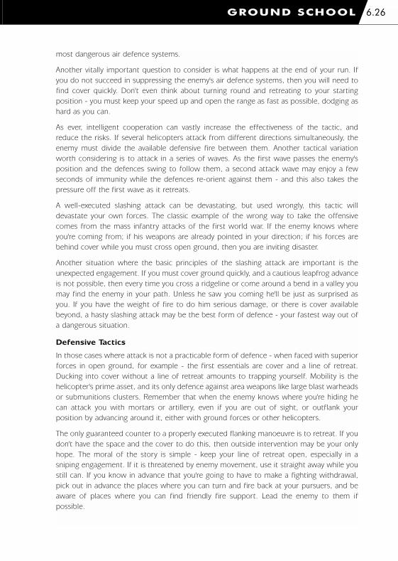
most dangerous air defence systems.
Another vitally important question to consider is what happens at the end of your run. If
you do not succeed in suppressing the enemy's air defence systems, then you will need to
find cover quickly. Don't even think about turning round and retreating to your starting
position - you must keep your speed up and open the range as fast as possible, dodging as
hard as you can.
As ever, intelligent cooperation can vastly increase the effectiveness of the tactic, and
reduce the risks. If several helicopters attack from different directions simultaneously, the
enemy must divide the available defensive fire between them. Another tactical variation
worth considering is to attack in a series of waves. As the first wave passes the enemy's
position and the defences swing to follow them, a second attack wave may enjoy a few
seconds of immunity while the defences re-orient against them - and this also takes the
pressure off the first wave as it retreats.
A well-executed slashing attack can be devastating, but used wrongly, this tactic will
devastate your own forces. The classic example of the wrong way to take the offensive
comes from the mass infantry attacks of the first world war. If the enemy knows where
you're coming from; if his weapons are already pointed in your direction; if his forces are
behind cover while you must cross open ground, then you are inviting disaster.
Another situation where the basic principles of the slashing attack are important is the
unexpected engagement. If you must cover ground quickly, and a cautious leapfrog advance
is not possible, then every time you cross a ridgeline or come around a bend in a valley you
may find the enemy in your path. Unless he saw you coming he'll be just as surprised as
you. If you have the weight of fire to do him serious damage, or there is cover available
beyond, a hasty slashing attack may be the best form of defence - your fastest way out of
a dangerous situation.
Defensive Tactics
In those cases where attack is not a practicable form of defence - when faced with superior
forces in open ground, for example - the first essentials are cover and a line of retreat.
Ducking into cover without a line of retreat amounts to trapping yourself. Mobility is the
helicopter's prime asset, and its only defence against area weapons like large blast warheads
or submunitions clusters. Remember that when the enemy knows where you're hiding he
can attack you with mortars or artillery, even if you are out of sight, or outflank your
position by advancing around it, either with ground forces or other helicopters.
The only guaranteed counter to a properly executed flanking manoeuvre is to retreat. If you
don't have the space and the cover to do this, then outside intervention may be your only
hope. The moral of the story is simple - keep your line of retreat open, especially in a
sniping engagement. If it is threatened by enemy movement, use it straight away while you
still can. If you know in advance that you're going to have to make a fighting withdrawal,
pick out in advance the places where you can turn and fire back at your pursuers, and be
aware of places where you can find friendly fire support. Lead the enemy to them if
possible.
GROUND SCHOOL 6.26
1036 EE-CH Manual - Chap 6 23/3/00 12:44 pm Page 6.26

Air-to-Air Tactics
If you have to fight another combat helicopter, or an aircraft, remember the mantra "this is
not a jet fighter". To a fighter pilot, altitude is a resource, a source of potential energy to be
converted into speed. To you, as a combat helicopter pilot, altitude means exposure to
enemy ground fire. Speed, too, works differently for a helicopter pilot. If an enemy aircraft
makes a high-speed slashing attack on you while your own speed is low, the advantage
swings to you as soon as the enemy is past. He is the prisoner of his own momentum, you
can pedal-turn and launch your own weapons from his blind spot.
Use cover and ambush tactics when the enemy is chasing you. When you're chasing him,
beware of the same tactics. Some classic air-to-air doctrines still apply to helicopter
combat; If you're part of a formation attacked by enemy helicopters, the formation should
split up. At the least, the enemy must divide his forces to pursue the different elements. If
the enemy leaves any of your elements unengaged, these should then turn around and
come in on the enemy's own tail.
Another classic air-combat tactic that may work for you is turning towards your opponent's
approach. This brings your own weapons to bear and shortens his firing time.
Using Ground-attack Weapons in Air Combat
Even if you're not carrying specialised air-to-air missiles, you should be aware of the anti-
aircraft potential of your ground-attack weapons. Cannon, rockets and anti-tank missiles
may all be usable, if less than ideal. If you have to use these weapons against aircraft, try
to do it at short range, and set up a low-deflection shot from ahead or behind. Remember
that your guided weapons may fly a pursuit path to the target, rather than an intercept
path, which reduces their effective range. Anti-tank missiles also generally have lower
acceleration and top speeds, higher drag, and much less agility than anti-aircraft missiles -
launching a Hellfire at a passing or retreating fast jet is most likely to achieve nothing more
than the waste of an expensive missile.
GROUND SCHOOL6.27
1036 EE-CH Manual - Chap 6 23/3/00 12:44 pm Page 6.27

7. COMANCHE VERSUS HOKUM
1036 EE-CH Manual - Chap 7 23/3/00 12:47 pm Page 1

COMANCHE VERSUS HOKUM7.1
RAH-66 Comanche
Carrying on the design tradition of American attack helicopters with the tandem cockpit and
turreted nose cannon, the RAH-66 Comanche also brings a suite of new technologies
shaped to fit the US Army’s 21st century vision. It is a vision often described using terms
such as efficiency, economy, flexibility and rapid-deployment. With the reduction of military
strength after the cold war and the increasing involvement of the US Army in "Operations
Other Than War", it has become evident that future forces need to be of a higher quality.
They need to deploy anywhere in the world rapidly and win in combat with the minimum
number of casualties.
Combining systems initially developed for the Apache and Light Helicopter Experimental
(LHX) program with new high-technology systems, the Boeing Sikorsky RAH-66 Comanche
represents the state-of-the-art in attack helicopters.
Visually, the most striking feature is the exterior body shape. Using what is known as low
observable (LO) properties, the fuselage is designed to reflect radar energy away from any
transmission source. Boeing claims the radar signature is around 1/300th of current aircraft.
To maintain a low radar profile, stores can be hidden in IRAMS (Integrated Retractable
Munitions System), this is an internal weapons bay capable of holding 6 Hellfire missiles.
1036 EE-CH Manual - Chap 7 23/3/00 12:47 pm Page 7.1

COMANCHE VERSUS HOKUM 7.2
Mounting stores internally in such a
way prevents any radar energy being
deflected back off the weapon and
thus increasing the helicopter’s radar
cross section (RCS). Should the
mission profile call for firepower
over stealth then additional weapons
may be fitted under removable
wings. A total of 14 Hellfire missiles
can be fitted in this configuration.
The Comanche has an advanced
bearingless composite rotor with
swept blade tips that reduces its
acoustic signature, particularly at the
reduced RPM levels of the so-called
"quiet" flight mode. The low-noise
rotor system, reduced infrared exhaust and small radar cross-section make the Comanche
the stealthiest helicopter in the world. While not invisible to radar it is much harder to
detect at longer ranges.
Sensors are mounted on the nose and top of the rotor mast in a similar configuration to
the AH-64D Longbow Apache. Indeed the RAH-66 boasts the next generation Longbow
radar system that is half the size of the previous model fitted to the Apache D model.
Mounted on the nose is a second generation FLIR (forward looking infrared), this has
double the resolution of the FLIR pod fitted to the Apache. This second generation FLIR
permits more reliable target recognition at 40% greater range. With 100% greater
resolution and 35% greater field of view, it is much safer for night flying which should give
some comfort to the crew.
In populated regions the greatest threat to a helicopter operating at night comes from
suspended or overhead cables. Whenever conventional helicopters are lost or damaged it is
usually through a cable strike. The improved FLIR can resolve cables that have small currents
running through them; electrical currents heat up wire to a point where they begin to "glow"
by a small amount in the infrared spectrum. To further reduce the risk of wire strikes, the
Comanche is fitted with a wire detector that provides an audible warning should it stray too
close to a current carrying cable.
Flying the AH-64 Apache using the PNVS (pilots night vision system – presented via a
helmet mounted monocle) has been described as, "trying to fly a helicopter by looking
through a drinking straw". The RAH-66 comes with a 53° wide field of vision holographic
helmet mounted display system and is biocular. Called HIDSS, the Helmet Integrated Display
and Sight System delivers FLIR sensor, flight and targeting symbology to both eyes. As in
the Apache, weapon targeting can be slaved to the pilots’ helmet movements. Wherever the
pilots look, the helicopter sensors will follow. In addition to this, the chin mounted 20mm
GIAT Vulcan-II cannon can also be slaved to follow the pilots’ head movements. When not
in use, the cannon is normally stowed in a LO cowling positioned under the chin.
1036 EE-CH Manual - Chap 7 23/3/00 12:47 pm Page 7.2

Front and rear cockpit configurations are near identical. The fly-by-wire flight control
system is triply redundant, the cyclic side-stick includes a twist action which controls aircraft
yaw. When used with flight assist modes the Comanche can be flown with just one hand.
This makes the Comanche a remarkably easy aircraft to control.
The cockpit is over-pressurized to prevent any possible crew contamination from NBC -
nuclear, biological or chemical agents. Should the cockpit suffer a minor breach after an
attack the positive cabin pressure will prevent any contaminant invading the crew area.
On-board computing power is equivalent to four super computers, however only 10% of
this power is needed to fly the aircraft; the rest is utilized in a highly advanced mission
equipment package. For target acquisition, there is automatic visual and radar target
recognition. Depending on the orientation of the target to the sensor, the computer can
distinguish not only between wheeled and tracked vehicles, but also determine vehicle type.
It has the remarkable ability of recognizing the difference between an M1 Abrams and
a T-80.
EO sensors can be set to visually scan a crew-designated sector and automatically classify
and track high-priority targets detected within that sector. Target removal is via man-in-the-
loop battle damage assessment, if a target has been hit and destroyed, the operator is
required to confirm destruction before it is removed from the tactical picture.
Sensor information can be shared with other elements of the combined arms team via a
"tactical internet". Command & Control (C2), ground forces, JSTARS, AWACS, indeed any
compatible system can exchange correlate and share tactical information with the
Comanche systems. Supported protocol stacks include; AFTDS, AFAPD, TACFIRE, VMF, and
MTS. Other tactical information distribution systems can be easily incorporated.
For communications, an existing system known as Air Force Integrated Communications
Navigation Identification Avionics, is used for interoperability. In addition there are two VHF-
FM single channel ground and airborne radio systems, a VHF-AM radio set and a HF (high
frequency) radio for non-line of sight communications. An IDM or Improved Data Modem
is used for communicating with the tactical internet.
Mission planning and rehearsal can be done completely in-cockpit using the advanced
"Tactical Mode". Digital terrain maps provide elevation and feature data, which are optionally
overlaid with a tactical situation display then rendered in plan or a real-time 3D perspective
view. The map can be overlaid with threat forces, friendly positions, waypoint information
and calculate intervisibilities. It can be used for threat avoidance or enroute mission
planning. Positional information comes from a composite GPS/Doppler/Inertial navigation
system that is constantly cross-checking and updating itself.
Each processor is an easily replaceable module common to the Air Force and Navy. If a
module should fail, the systems reconfigure themselves allowing the Comanche to remain
in battle and continue its mission despite malfunctions or battle damage.
Analysis of conducted exercises have shown that maneuverability, rate of climb, tandem
(instead of side-by-side) cockpit configuration and a turreted gun are winning combinations
in head to head helicopter engagements.
COMANCHE VERSUS HOKUM7.3
1036 EE-CH Manual - Chap 7 23/3/00 12:47 pm Page 7.3

COMANCHE VERSUS HOKUM 7.4
Development History
Back in 1981, a plan was drawn up for a single basic utility helicopter called LHX (Light
Helicopter Experimental). The intention was to replace the aging UH-1, OH-58 and AH-1
fleets with a production run of 5,000 LHXs. To fulfil the diverse mission roles currently
undertaken by the existing fleet, different LHX models were to be equipped with a large
variety of new technologies and mission equipment packages. While it was considered to
be an expensive program, military spending was generous under the current administration.
Six years later in 1987 these mission roles were substantially reduced to scout and attack
only. The projected LHX requirement then fell to around 2,000.
The upgrade/replacement program needed a rethink and quite possibly a different
helicopter better suited to the narrower mission profile. In 1988 the Department Of
Defense issued a "Request for Proposals", the request received a rapid response from
Boeing Helicopters in collaboration with Sikorsky Aircraft.
In 1990, the projected number of new helicopters required was further reduced to 1,292
with an option of a further order of some 400. A year later, the Boeing Sikorsky partnership
was awarded a contract to build 4 prototypes, designated the RAH-66 (RAH being an
acronym of Reconnaissance Attack Helicopter).
Modernisation programs for the Apache and Kiowa were started with a view to enhance
real-time intelligence gathering and distribution capabilities. These programs helped shape
Army XXI’s view of the electronic battlefield and have in-turn influenced Comanche systems
specification.
A combination of cost reviews and specification changes initially resulted in patchy
development. At present, the Boeing Sikorsky team manages some 1,100 major
subcontractors and suppliers across the United States, quite a feat of co-ordination. Recent
successes with two flying prototype Comanches have been good news for the program. The
U.S Defense Department has approved an early operational capability program, which will
provide six additional aircraft to the U.S Army so they can begin operational testing. These
new aircraft will be manufactured in 2001.
Meanwhile, digitization programs of OH-58 Kiowa and AH-64D Apache continue, results
suggest both platforms can be integrated more closely with ground forces than previously
thought. They will integrate well with the Comanche when it becomes operational and
eventually the older OH-58 will be finally phased out.
Initial operating capability (IOC) for the U.S Army’s Comanche is set for 2006. While the
Comanche has its critics in the Senate and Pentagon, in the Army there is no doubt that the
RAH-66 will be an indispensable asset in the early 21st century battlefield.
1036 EE-CH Manual - Chap 7 23/3/00 12:47 pm Page 7.4

COMANCHE VERSUS HOKUM7.5
Specifications - RAH-66 Comanche
Country Of Origin USA
Type Reconnaissance Attack Helicopter
Manufacturer Boeing Sikorsky
Dimensions
Main Rotor Diameter 12m (39ft 0.48 in)
Overall Length 14.2m (46ft 9.36 in)
Height 3.5m (11ft 7 in)
Fuselage Width 2.8m (9ft 3 in)
Weight
Normal take-off 3,522 kg (7,765lbs.)
Maximum take-off 5,845 kg (12,880 lbs.)
Primary Mission 5,276 kg (11,632 lbs.)
Power Plant
Turboshafts 2 x T800-LHTEC-801 Turboshaft
Take-off Power 2 x 1562 shp (shaft horse power)
Fuel (internal) 302 U.S gallons
Fuel (external) 900 U.S gallons
Performance
Never Exceed Speed 200 kts (370 km/h)
Cruise Speed 165 kts (305 km/h)
Maximum Rate of Climb at sea level 260 m/min (850 ft/min)
Hover Turn Rate 80° per/sec
Maximum Sideways Speed 60 kts (112 km/h)
Range (internal fuel) 485 km
Range (ferry tanks) 2,335 km
1036 EE-CH Manual - Chap 7 23/3/00 12:47 pm Page 7.5
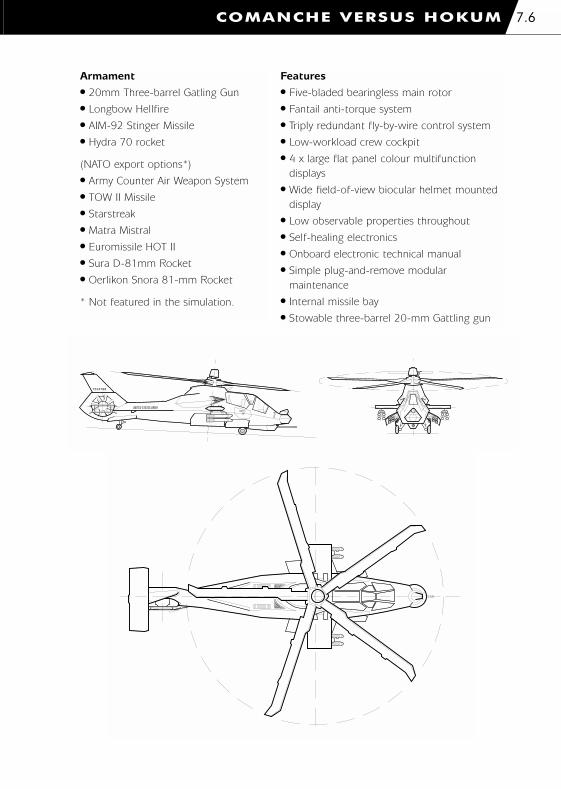
COMANCHE VERSUS HOKUM 7.6
Armament
� 20mm Three-barrel Gatling Gun
� Longbow Hellfire
� AIM-92 Stinger Missile
� Hydra 70 rocket
(NATO export options*)
� Army Counter Air Weapon System
� TOW II Missile
� Starstreak
� Matra Mistral
� Euromissile HOT II
� Sura D-81mm Rocket
� Oerlikon Snora 81-mm Rocket
* Not featured in the simulation.
Features
� Five-bladed bearingless main rotor
� Fantail anti-torque system
� Triply redundant fly-by-wire control system
� Low-workload crew cockpit
� 4 x large flat panel colour multifunction
displays
� Wide field-of-view biocular helmet mounted
display
� Low observable properties throughout
� Self-healing electronics
� Onboard electronic technical manual
� Simple plug-and-remove modular
maintenance
� Internal missile bay
� Stowable three-barrel 20-mm Gattling gun
UNITED STATES ARMY
524798
RESCUERESCUE
7
1036 EE-CH Manual - Chap 7 23/3/00 12:47 pm Page 7.6

COMANCHE VERSUS HOKUM7.7
Ka-52 Hokum B "Alligator"
Created by the Kamov Design Bureau, the unusual co-axial rotor configuration has in some
small way become one of the company’s trademarks. Anti-armour helicopter design usually
copies the Bell AH-1 Cobra configuration, tandem cockpit, single main rotor and anti-
torque tail rotor.
Kamov’s design approach is tempered by the view that the typical tail-rotor configuration
imposes an unnecessarily high-degree of vulnerability to ground fire. Also the long
transmission shaft and associated gearbox places high-loads on the tail boom, a structure
vulnerable to ground strikes and contact damage when hovering in confined spaces.
Eliminating the anti-torque rotor and associated gearbox transmission is achieved by
adopting a twin rotor configuration. One rotor is mounted above the other and spin in
opposite directions thus cancelling the effect of torque. This system makes ground
maintenance easier and more importantly to a pilot - increases helicopter performance,
nearly all the power provided by the two turboshaft engines is delivered straight to the main
rotor. There is no need to use power driving a tail rotor that doesn’t provide any lift.
Increased power allows for heavier armament more armour protection and greater speed –
all of these are fundamental constraints when designing a battlefield helicopter.
The co-axial rotor configuration of the Ka-52 has other benefits; the helicopter is capable
of performing flat-turns throughout the entire flight speed range. This affords an ability to
rapidly turn the nose onto a target even at dash speeds or rapid sideways transitioning to
1036 EE-CH Manual - Chap 7 23/3/00 12:47 pm Page 7.7

COMANCHE VERSUS HOKUM 7.8
evade fire while attacking. Mechanics are battle-hardened, systems have been proved
against rounds up to 23mm, the power-plant can run for 30 minutes without oil, this gives
the pilot an opportunity to land in a safe location in the event the oil system is damaged.
The Alligator is a high-performance all-weather, day and night attack helicopter. The primary
mission role being similar to the Comanche - battlefield reconnaissance and strike co-
ordination. To achieve this, there is an impressive avionic and sensor fit.
First is the FH-01 Arbalat (Crossbow) centimetric and millimetric wavelength radar made
by Phazotron. The centimetric antenna of the Crossbow has a 360-degree search capability
and mounted in a small 2-foot diameter dome on top of the rotor mast. This provides the
Ka-52’s air search and track capability. The larger millimetric wave antenna mounted in the
nose of the helicopter is used to detect ground objects (such as vehicles) and provide
information for 3D terrain mapping avionics. Little is known about the search parameters
of the Crossbow, estimates place it’s ground search and track capability in excess of 11km.
The helicopters electro-optical package consists of a number of systems. Like the American
AH-64 and RAH-66 combat helicopters, there are two discreet night vision sensors, one for
the pilot and another for weapon sighting. A sensor ball positioned on the roof between
the cockpit and the rotor mast houses the Samshit (Boxwood) STS gyro-stabilized
reconnaissance & sighting unit. The Samshit incorporates a FLIR imager (PNVS), which
feeds the pilots’ helmet-mounted display. Located under the fuselage is a small
hemispherical fairing which houses the weapon operators’ periscope: its rotation and
elevation is aligned with the Samshit pod. Laser designation and LLLTV (Low Light Level
Television) weapon guidance is achieved using a standard Shkval-V turret; this flat windowed
chin mounted housing is used for employing most of the Ka-52’s beam riding weapons
such as the supersonic Vikhr (Whirlwind). The accuracy of the target guidance system is so
great, it is said you can choose which "wheel" to hit on targets as far as 8 to 10km away.
Because of this accuracy the Vikhr can be used against air-to-ground or air-to-air targets,
the missile adjusts its profile accordingly.
The "Glass Cockpit" is a new feature in Kamov helicopters, four French made multi-function
colour displays provide most of the instrumentation and systems management required for
flight operations. An advanced EWS (Electronic Warfare Suite) provides early warning and
countermeasures; basic components are the RWR (Radar Warning Receiver), Missile
Warning System (MWS), Laser Warning Receiver (LWR) and chaff / flare launchers. The EWS
displays threat information on a moving map display allowing the crew to relate threat
bearing and distance to their immediate surroundings. Together with information from the
radar and electro-optical sensors, this target data is automatically exchanged via a digital
communications system to other force elements.
Navigation utilizes a combination of Inertial Guidance (laser gyroscopes and accelerometers)
and GPS signals from both GLOSNASS and NAVSTAR satellites. This positional information
is fed to an electronic moving map display that can be called up on one of the MFDs and
also transmitted digitally to a ground command centre. Radio outfitting is made up of three
VHF transceivers; one for monitoring the "guard" channel, one for secure communications
and another for communicating with other mission specific force elements.
1036 EE-CH Manual - Chap 7 23/3/00 12:47 pm Page 7.8

Gun installation consists of a 30mm 2A32 cannon mounted on a hydraulic drive that allows
a limited amount of deflection: -2° to +9° azimuth (side to side) and +3° to -37° elevation
(up and down). Cannon ammunition is supplied from two cartridge boxes, the fore box
contains 240 rounds of armor piercing tracers, and the rear box contains 230 high-explosive
incendiary rounds. The pilot selects which kind of ammunition to feed the gun and chooses
between two rates of fire: high (550-600 rounds per minute) or low (350 rounds per
minute). Burst lengths are automatically adjusted to either 10 or 20 rounds according to
the rate of fire.
Kamov has gone to considerable lengths for crew protection. Just as with the Comanche,
the crew cockpit is slightly pressurized to prevent NBC contamination. Protecting the crew
from ground fire is approximately 300kg (661 lbs.) of steel hybrid armor in two layers. The
steel armor is proved against direct hits by 20mm rounds. Lighter ceramic armor was
rejected due to its tendency to shatter after successive impacts. In an emergency landing,
the fuselage and landing gear struts can crumple to absorb large impact forces. Cockpit
components and other structural elements are designed to preclude crew compartment
volume compression by no more than 10-15%.
Another unusual feature of this helicopter is the "Pilot Rescue" capability by way of the K-
37-800 ejection seat which was first fitted to the Ka-50 (the first helicopter in the world
to be fitted with an ejector seat). Once the ejection handle has been pulled, a very carefully
timed series of events take place. First, explosive charges in the rotor blade roots are
detonated resulting in the separation of all 6 blades (this is potentially dangerous for any
nearby onlookers). Both cockpit canopies are ejected sideways then the towing rocket on
both ejection seats fire in low-thrust mode. When the towing-line is pulled taught the
rocket increases thrust pulling the seat up on its mounting rails and out of the helicopter.
After the rocket burn, the seat falls away and a cute is deployed. This ejection can be
performed throughout the entire flight envelope including inverted flight (given a minimum
altitude of 90 meters). Should a pilot eject over water, the seat is also fitted with survival
pack and life raft. A survival beacon is activated automatically on ejection.
The Ka-52 is simple to control, highly maneuverable and has a lethal day/night weapons
capability. A valuable asset for any modern army.
Development History
Since the mid-1970’s, the mainstay of the soviet attack helicopter fleet was the Mi-24 Hind.
This rather large and heavy helicopter, originally built as a flying Infantry Fighting Vehicle
(IFV), has a capacity for ferrying up to 8 fully equipped soldiers. Over the years, it was
realised that this troop carrying capability was underused; smaller lightweight (and more
manoeuvrable) helicopters proved more suited to the anti-armour role. The USSR
government took the decision to initiate the development of the next generation of army
helicopters in December 1976. The task was handed to the Kamov Design Bureau and the
Mil Helicopter Plant of Moscow.
In the early 1980’s, Kamov demonstrated its light attack helicopter concept, it was
designated V-80 (for "Helicopter of the 80s", V = "vertolyot" meaning helicopter). This
helicopter was later re-designated the Ka-50 Hokum. In June 1982, the first Ka-50
prototype designated "White 010" made its maiden flight.
COMANCHE VERSUS HOKUM7.9
1036 EE-CH Manual - Chap 7 23/3/00 12:47 pm Page 7.9

By 1990, soviet Army Aviation (Armeiskaya Aviatsiya) published its requirement for an anti-
tank helicopter with night fighting capability. The Mil Helicopter Plant of Moscow submitted
its two-seat Mi-28 Havoc and Kamov demonstrated their single-seat Ka-50 Hokum. Both
officially won tender in 1994 and a year later, President Yeltsin signed a decree
commissioning the Ka-50 for military service.
The first airframe left its Siberian factory in 1992. However lack of money forced
production to stop after only 12 airframes had been built, and most of those did not meet
the night flying requirement. As a result, Mil continued development of the Havoc, giving
the company a chance to develop better night flying technologies and offer a more
attractive helicopter.
With the difficulty in manufacturing heat vision equipment at that time, emphasis was
placed on radar development. The Mi-28 and Ka-50 used the prototype Almaz and Arbalat
(Crossbow) radar systems respectively. Advances in radar and FLIR design resulted in a
much more complex avionic suite in both helicopters. This proved to be a great
disadvantage in the single-seat Ka-50 where the pilot workload was considerably greater.
Given the high weight of Soviet avionics, fitting a comprehensive suite of avionic systems to
a two-seat helicopter was deemed impractical.
As it happens, a two-seat version of the Ka-50 had been constructed, used for pilot training
it featured a side-by-side cockpit configuration. By adding more powerful engines and
reducing protective armour, a practical two-seat attack helicopter was demonstrated.
Further to this, Kamov contracted western companies to supply lighter and user-friendlier
avionic components.
The first Ka-52 prototype designated "White 061" was premiered at the "Bangalore Aero
India" show in 1996. It was based on the 11th production Ka-50 with a rebuilt front-
fuselage section. It is estimated the Ka-52 is around 80-85 percent identical to the basic
Ka-50 helicopter airframe and main system components. The principal dimensions of both
helicopters remain more or less the same. White 061 was flown for the first time on the
25th June 1997 at Kamov’s flight test base in Lyubertsty.
Experience with the Mi-24 Hind in Afghanistan had convinced Kamov that better crew co-
ordination could be achieved by crew members sitting next to each other. Although
interestingly Mil was not so convinced, and neither was Turkey when it evaluated the Hokum
in 1998. Consequently this marked the start of an unlikely east/west relationship; Kamov in
collaboration with Israeli Aircraft Industries (IAI) began work on the Ka-50-2. This is an
export variant of the Ka-50/52 but has options for a traditional tandem cockpit and a
turreted 20mm cannon mounted under the belly. The IAI sensor fit includes a night
targeting and laser range-finder/designator package compatible with a subset of western
missile systems.
Kamov are currently offering Armeiskaya Aviatsiya a mixed package of Ka-52s with existing
Ka-50s upgraded to an all weather/night attack capability. Together they will adopt roles of
battlefield reconnaissance, target identification/distribution and hand-off in a similar fashion
to the AH-64D Apache and AH-64D fitted with the Longbow radar/fire control system.
COMANCHE VERSUS HOKUM 7.10
1036 EE-CH Manual - Chap 7 23/3/00 12:47 pm Page 7.10

Specifications – Ka-52 Hokum B
Country Of Origin Russia
Type Reconnaissance Attack Helicopter
Manufacturer Kamov Design Bureau
Dimensions
Main Rotor Diameter 14.5m (47ft 5 in)
Overall Length 13.5m (44ft 3 in)
Height 4.9m (16ft 2 in)
Fuselage Width 2.6m (8ft 7 in)
Weight
Normal take-off 10,400 kg (22,928 lbs.)
Maximum take-off 11,300 kg (24,910 lbs.)
Primary Mission 1,811 kg (4000 lbs.)
Power Plant
Turboshafts 2 x TV3-117VMA-SB3s Turboshaft
Take-off Power 2 x 2,500 shp (shaft horse power)
Fuel (internal) 3,271 lbs.
Fuel (external) 3,792 lbs.
Performance
Never Exceed Speed 350 km/h (189 kts)
Cruise Speed 310 km/h (167 kts)
Hover Ceiling (out of ground effect) 5,500m (18,050 ft)
Maximum Rate of Climb at sea level 480 m/min (1,575 fpm)
Hover Turn Rate 80° per/sec
Range (internal fuel) 460 km
Range (ferry tanks) 1,200 km
COMANCHE VERSUS HOKUM7.11
1036 EE-CH Manual - Chap 7 23/3/00 12:47 pm Page 7.11

Armament
� 2A42 30mm cannon*
� S-8 80mm Rocket*
� S-13 122mm Rocket*
� Vikhr-M (AT-9) Laser Guided air-to-
surface *
� Igla-V air-to-air missile*
� Kh-25ML (AS-12 Kegler) Laser
Guided air-to-surface
� Kh-25MP anti-radar missile
� R-73 (AA-11 Archer) air-to-air
missile
� KMGU-2 submunitions dispenser
� UPK-23 Gun Pod Twin 23mm*
� 500-kg aerial bomb
� 250-kg aerial bomb
* Featured in the simulation.
COMANCHE VERSUS HOKUM 7.12
Features
� Co-axial rotor configuration
� Zvezda K-37-800 pilot ejection system
� Phazotron FH-01 Arbalat (Crossbow)
CMW/MMW radar
� Shkval-V gyro-stabilized recon unit with TV,
FLIR and Laser
� Under hull turret-mounted periscope
� Target data exchange over digital
communications
� Automatic flight-control system
� Glass cockpit with Multi-Function Colour
Displays
� Hands On Collective And Stick (HOCAS)
� Helmet Mounted Display
� High power-to-weight ratio
� Reduced Pilot Workload
1036 EE-CH Manual - Chap 7 23/3/00 12:47 pm Page 7.12

COMANCHE VERSUS HOKUM7.13
Performance Comparison Table
RAH-66 Comanche Ka-52 Hokum B
Never Exceed Speed 200 kts. 188 kts.
Max Forward Speed 172 kts (318 km/h) 161 kts (298 km/h)
Max Sideways Speed 60 kts 43 kts
Rate Of Climb (at sea level) 260 m/min (850 ft/min) 1,574 ft/min
Range (internal) 485 lm 450 km
Range (ferry) 2,335 km 1,200 km
Engine Output 2 x 1,563 shp 2 x 2,500 shp
Weight Max 5,845 kg 10,800 kg
Used Acronyms
AFAPD Air-Force Applications Program Development
AFTDS Advanced Field Artillery Tactical Data System
CMW Centimetric Wave
EO Electro Optics
EWS Electronic Warfare Suite
FLIR Forward Looking Infra Red
HF High Frequency
HIDSS Helmet Integrated Display & Sight System
HOCAS Hands On Collective and Stick
IDM Improved Data Modem
IOC Initial Operating Capability
I-RAMS Integrated Retractable Munitions System
LLLTV Low Light Level Television
LO Low Observable
MMW Millimeter Wave
MTS Marine Tactical Systems
NBC Nuclear Biological Chemical
PNVS Pilot Night Vision System
RCS Radar Cross Section
TACFIRE TACtical FIRE direction system
VMF Variable Message Format
1036 EE-CH Manual - Chap 7 23/3/00 12:47 pm Page 7.13

8. CAMPAIGN SCENARIOS
1036 EE-CH Manual - Chap 8 23/3/00 12:48 pm Page 1

CAMPAIGN SCENARIOS8.1
Sword In The SandFor ten years both Saudi Arabia and Yemen have been squabbling over the exact
course of their mutual border, resulting in frequent armed clashes. As both sides re-
arm with state of the art equipment from their respective super power patrons the
discovery of rich oil deposits in the disputed region escalates the tension. Finally,
another confrontation on the border triggers one or both sides to lose patience and
the desert reverberates to the sound of helicopter engines as battle is joined over a
‘line in the sand’.
War Of IndependenceBeijing has always considered Taiwan to be part of China and talks between the two
to resolve this have continually broken down. For the Chinese the final straw was the
surprising victory of the Taiwan Independence Party (TIP) in the 2001 elections. The
PLA, having spent the last decade re-equipping with state of the art Russian
equipment, sees a window of opportunity to settle the issue by force of arms and
under cover of large scale naval manoeuvres launch a sudden invasion and rapidly
seize the northern side of the island. With the UN Security Council prevented from
taking action by the Russian veto the Americans rush a task force to the area
determined to prevent the Chinese from consolidating their bridgehead.
Task Force LebanonThe discovery of a plot by terrorists to detonate a nuclear warhead in Baltimore has
made the US determined to renew the war against terrorism. The perpetrators are
discovered to be sheltering in Lebanon and elements of the US 6th Fleet are
dispatched to the area. The Lebanese militias, backed up with Russian hardware
supplied through Syria, are determined to defend their homeland from American
incursions and a ‘swift surgical strike’ soon degenerates into a much wider conflict.
CentralAsia
Indian Ocean
South America
North America
Central Americaand the
Caribbean
Greenland
AustraliaPacific Ocean
AtlanticOcean
SouthernAfrica
Russian Federation
East Asia
South EastAsiaNorthern Africa
Europe
Arctic Region
SouthAsia
5000 km
5000 miles
Task ForceLebanon
Sword InThe Sand
War OfIndependence
1036 EE-CH Manual - Chap 8 23/3/00 12:48 pm Page 8.1

Sword In The Sand
CAMPAIGN SCENARIOS 8.2
Oman
Persian Gulf
Saudi Arabia
Iraq
Yemen
Red
Sea
From the Middle East Gazette
Blue Force Briefing (Saudi Arabia)
It appears that the Yemeni claims to the oil rich Marib border area have finally pushed the
Saudis too far. For years the Yemeni government has been provoking the Saudis over this
sensitive issue, the final straw being their granting of drilling rights in the disputed region
to various foreign oil companies (including several Russian concerns). This Russian
connection must not be overlooked. For several years the Russians, chafing under American
global dominance, have been re-establishing links with their old client states wherever
possible. They have been supplying an ever increasing amount of support to Yemen, possibly
to offset their loss of influence in the northern part of the Persian Gulf. It is rumoured, that
should the Yemeni government prevail in its claims along the Saudi border they will grant
the Russians naval basing rights at Aden (finally giving them what they have long craved - a
warm water port).
We must also not forget the Yemeni support given to Saddam Hussein during the invasion
of Kuwait. That this made them the outcasts of the Arab world seems to have made them
only more determined to pursue their claims on Saudi Arabian territory. They have recklessly
increased expenditure on their armed forces, despite the fact that they have long been
unable to meet the repayment schedules and some say there is almost an air of desperation
about this military adventure.
Despite this, the start of the conflict seems to have been carefully orchestrated by the
Yemeni government. First there was their open support of fundamentalists hostile to the
Saudi regime. This was swiftly followed by the show trials in Aden where hundreds of
dissidents were rounded up and made to testify to being part of some far fetched Saudi
plot. Then there was the government statement that Yemeni actions would be seen as ‘the
BLUEFORCE
1036 EE-CH Manual - Chap 8 23/3/00 12:48 pm Page 8.2

signal of a pan Arab awakening embodying the dreams of the Arab masses in a borderless
great Arab homeland, a unified nation’ (a statement chillingly similar to the one issued by
Hussein during his attempt to annex Kuwait) and finally there was the granting of the drilling
rights in the disputed border region.
The conflict appears to have erupted around several almost insignificant border villages -
including Ifrine and Al - Baqah, the clashes occurring during Saudi military manoeuvres. All
Saudi attempts at reconciliation have been rebuffed and now the conflict can only be
settled on the battlefield. Saudi units are already moving up to the border to put an end to
these provocations once and for all.
Partial transcript of a government broadcast to the Yemeni people
Red Force Briefing (Yemen)
Fellow Yemenis! Since 1969 Saudi Arabia has clung to the territory she illegally took from
us despite all our attempts to settle the matter peacefully. We are a new nation, born out
of the destruction of a dreadful civil war, anxious to be granted the hand of friendship.
Instead we have discovered only selfish enmity. Surely you would think that a poor country
such as ours would be allowed to share the mineral riches of the Marib in order that we
could rebuild our shattered cities and give some measure of comfort to our people. But no!
Our rich Saudi neighbours would not concede in this matter, despite the justness of our
cause. Not content with merely attempting to drive us into poverty they have continually
meddled in our affairs. They have sheltered the traitors who plunged us first into civil war.
They insulted our noble leader, calling him an ‘ignoramus’ and ‘parasitical and ignorant’.
But they do not only use words to attack us. They have steadily built up the size of their
army, despite the strain this so evidently places in their economy. When asked why they
claimed that it was for protection against Iraq. But if this is so, why was it necessary to hold
TEN days of live fire exercises along our border. Their plan became obvious when a plot was
discovered to place bombs throughout our country. Thankfully the ringleaders were
arrested before they could act and during their trial the truth emerged - that this vile
conspiracy was organised by our neighbour.
No doubt smarting at their failure the Saudi units on this so called exercise have crossed the
border and occupied the villages at Ifrine and Al - Baqah. It is now obvious that they
resolutely oppose any peaceful solution to the border question, and with a heavy heart we
have ordered our military units to defend our sovereign territory.
Our forces may be small, but it was they that unified our nation and they are still fiercely
proud of this great endeavour. Even now our soldiers are preparing to valiantly defend
Yemeni citizens so ruthlessly attacked by our implacable neighbours. Rest assured that they
will strike, and strike hard at our foes to avenge all the slights and humiliations heaped
upon us.
The struggle may be hard, the sacrifices many but we have come too far to be defeated
now. Our cause is just and our victory will be absolute!
REDFORCE
CAMPAIGN SCENARIOS8.3
1036 EE-CH Manual - Chap 8 23/3/00 12:48 pm Page 8.3
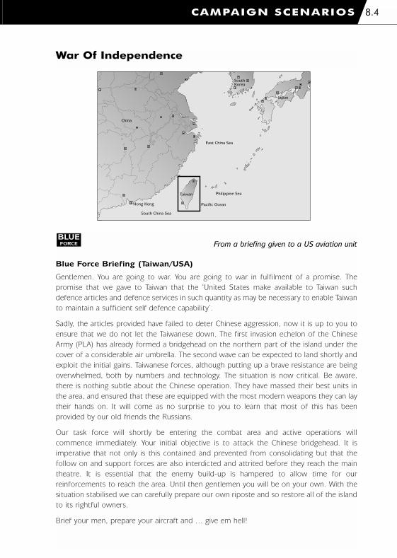
War Of Independence
CAMPAIGN SCENARIOS 8.4
East China Sea
Japan
SouthKorea
China
Philippine Sea
Pacific Ocean
Taiwan
South China Sea
Hong Kong
From a briefing given to a US aviation unit
Blue Force Briefing (Taiwan/USA)
Gentlemen. You are going to war. You are going to war in fulfilment of a promise. The
promise that we gave to Taiwan that the ‘United States make available to Taiwan such
defence articles and defence services in such quantity as may be necessary to enable Taiwan
to maintain a sufficient self defence capability’.
Sadly, the articles provided have failed to deter Chinese aggression, now it is up to you to
ensure that we do not let the Taiwanese down. The first invasion echelon of the Chinese
Army (PLA) has already formed a bridgehead on the northern part of the island under the
cover of a considerable air umbrella. The second wave can be expected to land shortly and
exploit the initial gains. Taiwanese forces, although putting up a brave resistance are being
overwhelmed, both by numbers and technology. The situation is now critical. Be aware,
there is nothing subtle about the Chinese operation. They have massed their best units in
the area, and ensured that these are equipped with the most modern weapons they can lay
their hands on. It will come as no surprise to you to learn that most of this has been
provided by our old friends the Russians.
Our task force will shortly be entering the combat area and active operations will
commence immediately. Your initial objective is to attack the Chinese bridgehead. It is
imperative that not only is this contained and prevented from consolidating but that the
follow on and support forces are also interdicted and attrited before they reach the main
theatre. It is essential that the enemy build-up is hampered to allow time for our
reinforcements to reach the area. Until then gentlemen you will be on your own. With the
situation stabilised we can carefully prepare our own riposte and so restore all of the island
to its rightful owners.
Brief your men, prepare your aircraft and … give em hell!
BLUEFORCE
1036 EE-CH Manual - Chap 8 23/3/00 12:48 pm Page 8.4

From a Chinese briefing to their armed forces
Red Force Briefing (China)
The situation with Taiwan has become intolerable. This after all is Chinese sovereign territory
yet its leaders have antagonised and insulted us. This perhaps could be borne with stoicism,
for we always said that eventually there would be a peaceful rapprochement between us.
However, now the situation threatens to spiral out of control and our patience is exhausted.
Unlike the restoration of Hong Kong and Macao a peaceful solution now seems impossible
to come by.
The new government of Taiwan, the so called ‘Taiwanese Independence Party’ has stated
quite unequivocally that they well be claiming independence from China. Such an
adventurist action removes any claim to legitimacy that this so called government might
have and we have resolved to undertake an action to remove them from power, finally
ending these splittest tendencies.
Rest assured that you will be embarking on this action with the full support of the Chinese
people behind you as this misguided island is restored to the protection of Beijing.
Do not undertake your duties lightly. Whilst there will be some resistance from the
reactionaries in Taiwan, we feel the challenge you must meet and overcome will come from
further afield. America has made no secret of its support for Taiwan and the opposition
from this quarter will have to be overcome before final victory is assured.
You are well equipped for the task at hand. We have left no stone unturned to obtain for
you some of the most modern weapons in the world. These have not only been produced
in our new advanced factories and shipyards but have been bought from far and wide. Many
have been provided by our friends the Russians. With ships, aircraft and missiles of the most
advanced types our comrades in the navy and airforce have pledged to deliver you safely on
Taiwan. It is then that your work will commence.
Equipment however can only do so much. It is upon your endeavours that the final decision
will rest. You must look to the example of your leaders and cadre as you march to obtain
the ultimate victory all our citizens so desperately crave.
REDFORCE
CAMPAIGN SCENARIOS8.5
1036 EE-CH Manual - Chap 8 23/3/00 12:48 pm Page 8.5

Task Force Lebanon
From a satellite news channel report
Blue Force Briefing (USA)
Who would have thought that a routine raid on a warehouse in Baltimore a few weeks ago
would culminate in an American Task Force standing off the coast of Lebanon? Although it
was a surprise to everyone when the FBI uncovered what turned out to be the equipment
for the manufacture of a nuclear weapon all parts of the American intelligence
establishment rapidly swung into action. The CIA traced the origin of the warheads
plutonium to the Russian Tomsk-7 site whose security has been worrying experts for years.
It appears that this material was smuggled out of Russia by the Mafia and into Turkey and
from here down into Lebanon. This was where it fell into the hands of the terrorist splinter
group ‘The Sword of Freedom’ which is reported to be based in the country. As soon as this
was verified, large elements of the 6th Fleet set sail for the eastern Mediterranean whilst a
retaliatory action was planned.
Unfortunately the situation today seems somewhat confused and the chance of a swift,
surgical strike is rapidly diminishing. The Lebanese Militias have declared that American
forces have no business in their waters and have been rapidly mobilising their forces. It has
now become apparent that Syrian support for these militias has been far more extensive
than was first thought. The Militias have revealed themselves to be in possession of top of
the range military hardware, most of which the Russians originally supplied to the Syrian
army. The crisis has caused the various factions to unify in the face of what they see as little
more than an American invasion and have pledged to resist any and all US incursions into
their territory. They have made no secret of the fact that they believe they have the weapons
to halt any US action dead in its track. Tensions have been raised to such a pitch that we
now find ourselves in a ‘hair trigger’ situation and full scale military operations could
commence at any minute.
BLUEFORCE
CAMPAIGN SCENARIOS 8.6
Lebanon
Syria
Jordan
Israel
Mediterranean Sea
Cyprus
1036 EE-CH Manual - Chap 8 23/3/00 12:48 pm Page 8.6

A spokesman for the Task Force Admiral told me that ‘whilst we have no wish to become
embroiled in a shooting match with the Militias we are worried by the very real possibility
that there may well be more of these weapons of mass destruction - or the material for
their construction somewhere in the Lebanon. It is imperative that our forces are allowed
to investigate this matter and punish those responsible. Whilst we seek the support of the
Lebanese people in this affair, we cannot, and will not, allow ourselves to be deterred by
their hostility’.
From a Syrian government press release to assembled journalists
Red Force Briefing (Lebanese Militias/Syria)
In the first place we want to make it absolutely clear that Syria does not support or sponsor
terrorist activities in any way. We do not do this now and will not do so in the future. We
vehemently deny the irresponsible accusations concerning Syrian involvement with this so
called ‘Sword of Freedom’ group. Indeed, we go further. We are not at all convinced that
such a group exists, or if it does, that it is based in Lebanon. As you all know we have taken
an active role in the rebuilding of that unhappy country and under our guidance and with
our support it is now returning to a normal way of life. Should all of this be jeopardised on
the say so of the American CIA? Has not this much vaunted organisation been wrong in the
past?
As we have said, we have no interest in terrorism and offer no succour to its perpetrators.
However, in the face of what can only be seen as an irresponsible and reckless American
adventure we absolutely maintain the right of the Lebanese people to actively defend
themselves with every means at their disposal. Over the years too many foreigners have
meddled in Lebanese affairs with no call to do so and this threatened American action is no
different. Finally with our support, and the assistance of our friends in Russia our colleagues
in Beirut have the weapons to protect themselves and we very much hope that this will
deter the Americans from their reckless and dangerous endeavour.
Should this deterrence fail be aware that Syria does not, and will not abandon its friends
and allies. We are fully prepared to furnish every assistance to the Lebanese in the face of
this gross American provocation.
Once more, we say again that every nation has the right to self defence and to resist outside
meddling in their internal affairs. America should be aware that Syria will ensure that the
Lebanese have, and will continue to have, the means with which to uphold this right.
REDFORCE
CAMPAIGN SCENARIOS8.7
1036 EE-CH Manual - Chap 8 23/3/00 12:48 pm Page 8.7

9. RECOGNITION GUIDE
1036 EE-CH Manual - Chap 9 23/3/00 12:50 pm Page 1

RECOGNITION GUIDE9.1
Type: Attack
AH-64A ApacheRecognition features:
� 4-bladed main rotor - no radome
- and 4-bladed X-shaped tail
rotor
� tandem cockpit arrangement
under single flat-glazed canopy
� stub wings with wingtip missile
mounts
� engine nacelles on each side of
fuselage with 'fish tail' exhaust
cooling vanes to rear
� slender symmetrical sponsons on
each side of cockpit blending
under fuselage nose section
� nose-mounted TADS / PNVS
turrets
� chain gun turret-mounted under
forward fuselage
� all moving tail plane
� fixed main undercarriage and tail
wheel
Armament:
� M230 30mm Chain Gun
� AIM-92 Stinger IR guided air-to-
air missiles
� AGM-114K Hellfire II laser guided
anti-tank missiles
� Hydra 70 M255 unguided rockets
(HE)
� Hydra 70 M261 unguided rockets
(MPSM)
Decoys:
� chaff
� flares
USA COMBAT HELICOPTERS
Game notes:
� radar symbol:
� ground radar priority: medium
1036 EE-CH Manual - Chap 9 23/3/00 12:50 pm Page 9.1

RECOGNITION GUIDE 9.2
Type: Attack
AH-64D ApacheLongbowRecognition features:
� 4-bladed rotor with ‘Swiss
cheese’ style radome, 4-bladed
‘X’ shaped tail rotor
� tandem cockpits with
single canopy
� stub wings with wing-tip
missile mounts
� engine nacelles on each side of
fuselage with ‘fish-tail’ exhaust
cooling vanes to rear
� enlarged flat-sided sponsons
(avionics bays)
� nose-mounted
TADS/PNVS turrets
� chain gun turret mounted under
forward fuselage
� all-moving tail-plane
� fixed undercarriage and tail wheel
Armament:
� M230 30mm Chain Gun
� AIM-92 Stinger IR guided
air-to-air missiles
� AGM-114L Longbow Hellfire
radar guided anti-tank missiles
� AGM-114K Hellfire II laser guided
anti-tank missiles
� Hydra 70 M255 unguided
rockets (HE)
� Hydra 70 M261 unguided
rockets (MPSM)
Decoys:
� chaff
� flares
USA COMBAT HELICOPTERS
Game notes:
� radar symbol:
� ground radar priority: medium
1036 EE-CH Manual - Chap 9 23/3/00 12:50 pm Page 9.2

Type: Attack
AH-1W SuperCobraRecognition features:
� broad twin rotor blades
� tall narrow fuselage, short ridged
tail boom with centrally mounted
tail plane, sharply backward
slanting tail fin
� narrow tandem cockpit
arrangement under single
rounded canopy, shallow
sponsons each side of forward
fuselage section
� rounded air intakes and engine
nacelles each side of fuselage
separated by raised ridge at rear,
distinctive twin elongated oval
exhaust outlets
� sharply pointed nose with conical
TADS turret under
� short stub wings with wing tip
weapons pylons and edge-on
ECM pods on upper wing surface
� chin-mounted triple-barrelled
nose gun turret
� squat landing skids under central
section
Armament:
� 20mm cannon
� AIM-92 Stinger IR guided air-to-
air missiles
� AGM-114K Hellfire II laser guided
anti-tank missiles
Decoys:
� chaff
� flares
RECOGNITION GUIDE9.3
USA COMBAT HELICOPTERS
Game notes:
� radar symbol:
� ground radar priority: medium
1036 EE-CH Manual - Chap 9 23/3/00 12:50 pm Page 9.3

RECOGNITION GUIDE 9.4
AH-1T SeaCobraRecognition features:
� broad twin rotor blades
� tall narrow fuselage, short ridged
tail boom with centrally mounted
tail plane, sharply backward
slanting tail fin
� narrow tandem cockpit
arrangement under single
rounded canopy
� elongated air intakes to rounded
engine nacelles each side of
fuselage joining in flat ended
projection at rear with twin
circular exhaust outlets
� sharply pointed nose with conical
TADS turret under
� short stub wings with wing tip
weapons pylons and edge-on
ECM pods on upper wing surface
� chin-mounted gun turret with
long triple-barrelled cannon
� squat landing skids under central
section
Armament:
� 20mm cannon
� AIM-92 Stinger IR guided air-to-
air missiles
� AGM-114K Hellfire II laser guided
anti-tank missiles
Decoys:
� chaff
� flares
USA COMBAT HELICOPTERS
Game notes:
� radar symbol:
� ground radar priority: medium
Type: Marine attack
1036 EE-CH Manual - Chap 9 23/3/00 12:51 pm Page 9.4

RECOGNITION GUIDE9.5
RAH-66 ComancheRecognition features:
� 5-bladed 'low profile' main rotor
with enclosed hub and mast-
mounted conical radome, integral
fenestron tail rotor
� distinctive angular stealth
composite fuselage design with
asymmetrical canted tail section
and canted T-shaped tail
configuration
� tandem cockpit arrangement
under single high visibility flush
sided canopy
� shallow angular engine nacelles
with distinctive triangular inlets
� conical nose-mounted TADS/PNVS
turret
� retractable weapons bay doors
with integral pylons, optional
detachable stub wings to provide
additional weapons hardpoints
� chin-mounted stowable cannon
turret
� retractable main undercarriage
and tail wheel
Armament:
� 20mm Gatling gun
� AIM-92 Stinger IR guided air-to-
air missiles
� AGM-114L Longbow Hellfire radar
guided anti-tank missiles
� AGM-114K Hellfire II laser guided
anti-tank missiles
� Hydra 70 M255 unguided rockets
(HE)
� Hydra 70 M261 unguided rockets
(MPSM)
USA COMBAT HELICOPTERS
Decoys:
� chaff
� flares
Game notes:
� radar symbol:
� ground radar priority: medium
� stealth features reduce
radar signature
Type: Reconnaissance/attack
1036 EE-CH Manual - Chap 9 23/3/00 12:51 pm Page 9.5

RECOGNITION GUIDE 9.6
OH-58D KiowaWarriorRecognition features:
� 4-bladed main rotor with large
mast-mounted spherical sight,
twin-bladed tail rotor
� tall and narrow curved fuselage,
flat sided engine compartment
atop with large ECM mount to
rear
� small sharply rounded nose
section with bubble glazed
cockpit giving distinctive 'bug-
eyed' appearance
� slender round-section tail boom
with centrally located tailplane
and twin fins to rear,
� squat landing skids under central
section
� upward cranked tubular external
stores supports for weapons
payloads
Armament:
� AIM-92 Stinger IR guided air-to-
air missiles
� AGM-114K Hellfire II laser guided
anti-tank missiles
Decoys:
� chaff
� flares
USA COMBAT HELICOPTERS
Game notes:
� radar symbol:
� ground radar priority: medium
Type: Scout
1036 EE-CH Manual - Chap 9 23/3/00 12:51 pm Page 9.6

Type: Attack/assault
UH-60 Black HawkRecognition features:
� 4-bladed main rotor and
4-bladed tail rotor
� twin seat side-by-side cockpit
� low and wide appearance to main
fuselage section with flat
underside and elongated nose
� sliding doors on either side of
main cabin
� IR suppressors fitted to engine
exhaust outlets
� external stores supports for
weapon pylons
� all-moving tail-plane
� fixed undercarriage and tail wheel
Armament:
� AGM-114C Hellfire radar guided
anti-tank missiles
� Hydra 70 M255 unguided
rockets (MPSM)
Decoys:
� chaff
� flares
RECOGNITION GUIDE9.7
USA COMBAT HELICOPTERS
Game notes:
� radar symbol:
� ground radar priority: medium
1036 EE-CH Manual - Chap 9 23/3/00 12:51 pm Page 9.7

Type: Marine assault
CH-46E Sea KnightRecognition features:
� twin 3-bladed tandem
main rotors
� twin seat side-by-side cockpit
inside glazed nose
� long rectangular fuselage with
elevated engine housings and
rearward stub wings
� rear hinged loading ramp to
cargo hold
� fixed tricycle undercarriage with
main rear wheels supported by
stub wings
Decoys:
� chaff
� flares
RECOGNITION GUIDE 9.8
USA COMBAT HELICOPTERS
Game notes:
� radar symbol:
� ground radar priority: medium
1036 EE-CH Manual - Chap 9 23/3/00 12:51 pm Page 9.8

Type: Medium-lift
CH-3 (Jolly Green Giant)Recognition features:
� 5-bladed main rotor and
5-bladed tail rotor
� twin seat side-by-side cockpit
behind shallow nose
� long main fuselage with sloping
rear section and short tail boom
� rear hinged loading ramp to
cargo hold
� semi-retractable tricycle
undercarriage with main rear
wheel housings in stub wings
Decoys:
� chaff
� flares
RECOGNITION GUIDE9.9
USA TRANSPORT HELICOPTERS
Game notes:
� radar symbol:
� ground radar priority: medium
1036 EE-CH Manual - Chap 9 23/3/00 12:51 pm Page 9.9

Type: Heavy-lift
CH-47D ChinookRecognition features:
� twin 3-bladed tandem
main rotors
� twin seat side-by-side cockpit
inside glazed nose
� long rectangular fuselage (bulging
along lower sides), elevated front
and rear engine housings
� external engine nacelles on rear
sides of fuselage
� rear hinged loading ramp to
cargo hold
� fixed 4-wheeled undercarriage
Decoys:
� chaff
� flares
RECOGNITION GUIDE 9.10
USA TRANSPORT HELICOPTERS
Game notes:
� radar symbol:
� ground radar priority: medium
1036 EE-CH Manual - Chap 9 23/3/00 12:51 pm Page 9.10

RECOGNITION GUIDE9.11
Type: Medium-lift tilt-rotor
MV-22 OspreyRecognition features:
� distinctive twin 3-bladed tilt-
rotors and rounded hub spinners
� high-wing configuration with
short wing sections supporting
large tilt rotor engine nacelles at
tips
� rounded square-section flat
bottomed fuselage, with large
bulging underwing sponsons
� short rounded nose section, side-
by-side cockpit arrangement
under single rounded canopy,
nose-mounted mini radome and
forward projecting refuelling
probe
� rear sloping fuselage section
rising to distinctive flattened and
curved rear tail boom supporting
twin finned tail plane with hinged
loading ramp to cargo hold under
� squat retractable tricycle
undercarriage
Decoys:
� chaff
� flares
USA TRANSPORT HELICOPTERS
Game notes:
� radar symbol:
� ground radar priority: medium
1036 EE-CH Manual - Chap 9 23/3/00 12:52 pm Page 9.11

RECOGNITION GUIDE 9.12
Type: Heavy-lift
CH-53E SuperStallionRecognition features:
� large 7-bladed main rotor with
flattened circular hub cap, canted
4-bladed tail rotor
� broad and long rounded square
sectioned fuselage sloping up to
short tail boom with flattened
underside, sharply canted tail fin
with distinctive cranked side-
mounted tail plane
� rounded engine housing tapering
along upper fuselage, large
outboard tubular air intakes with
conical intake filters, large angled
circular exhaust tubes to rear
� large curved sponsons at centre
section with projecting outer
supports for large droptanks
� distinctive rounded flat nose
section incorporating cockpit
nose glazing and forward
projecting refuelling probe
� rear hinged loading ramp to
cargo hold
� squat semi-retracting tricycle
undercarriage
Decoys:
� chaff
� flares
USA TRANSPORT HELICOPTERS
Game notes:
� radar symbol:
� ground radar priority: medium
1036 EE-CH Manual - Chap 9 23/3/00 12:52 pm Page 9.12

Type: Close air support
A-10A ThunderboltRecognition features:
� low-wing, square leading and
trailing edge with upward canted
outer sections and down-turned
wing-tips, projecting fairings over
main landing gear
� short nose with ‘up-front’
cockpit arrangement
� twin fin assembly
� large pair of circular engine
nacelles mounted on upper
rear fuselage
� many under-wing weapon
hard points and large nose
mounted cannon
� semi-retractable tricycle
undercarriage
Armament:
� 30mm cannon
� AIM-9M Sidewinder IR guided
air-to-air missiles
� LAU-69/A unguided rockets
Decoys:
� chaff
� flares
RECOGNITION GUIDE9.13
USA COMBAT AIRCRAFT
Game notes:
� radar symbol:
� ground radar priority: medium
1036 EE-CH Manual - Chap 9 23/3/00 12:52 pm Page 9.13

Type: Multi-role fighter
F-16 Fighting FalconRecognition features:
� mid-wing, swept leading edge,
square trailing edge, wings
blended to fuselage
� long bubble-shaped canopy and
short sharp nose
� single large curved air intake
under nose
� single large tail fin, downward
canted all-moving tail plane
� wing-tip missile mounts,
under-wing hard-points
� retractable tricycle undercarriage
Armament:
� 20mm cannon
� AIM-9M Sidewinder IR guided
air-to-air missiles
� AIM-120 AMRAAM radar guided
air-to-air missiles
� AGM-65D Maverick IR guided
air-to-surface missiles
Decoys:
� chaff
� flares
RECOGNITION GUIDE 9.14
USA COMBAT AIRCRAFT
Game notes:
� radar symbol:
� ground radar priority: medium
1036 EE-CH Manual - Chap 9 23/3/00 12:52 pm Page 9.14

AV-8B HarrierRecognition features:
� high-wing, swept leading
and trailing edges, sharp
downward cant
� swept tail fin, downward canted
all-moving tail plane
� compact bulbous fuselage with
rounded main air intakes
immediately aft of either side
of cockpit
� short nose with ‘up-front’
cockpit arrangement
� thrust vectoring nozzles under
wings on either side of fuselage
� under-wing hard-points, under-
fuselage bulging cannon housing
� retractable main landing gear
with under-wing retractable
stabilisers
Armament:
� 25mm cannon
� AIM-9M Sidewinder IR guided
air-to-air missiles
� LAU-69/A unguided rockets
Decoys:
� chaff
� flares
RECOGNITION GUIDE9.15
USA COMBAT AIRCRAFT
Game notes:
� radar symbol:
� ground radar priority: medium
Type: Carrier-borne attack
1036 EE-CH Manual - Chap 9 23/3/00 12:52 pm Page 9.15

F/A-18 HornetRecognition features:
� mid-wing, swept leading edge
extended into ‘hood’ along
forward fuselage, square
trailing edge
� long slender nose section and
canopy, with wings centred well
aft of fuselage centre line
� swept all-moving tail plane well
aft of tall sharply canted twin
tail fins
� engine intakes either side of
fuselage under wing leading
edge, closely-spaced rear nozzles
� under-wing and fuselage
hard-points with wing-tip
missile mounts
� retractable tricycle undercarriage
Armament:
� 20mm cannon
� AIM-9M Sidewinder IR guided
air-to-air missiles
� AIM-120 AMRAAM radar guided
air-to-air missiles
� AGM-65F Maverick IR guided
air-to-surface missiles
Decoys:
� chaff
� flares
RECOGNITION GUIDE 9.16
USA COMBAT AIRCRAFT
Game notes:
� radar symbol:
� ground radar priority: medium
Type: Carrier-borne interceptor
1036 EE-CH Manual - Chap 9 23/3/00 12:52 pm Page 9.16

RECOGNITION GUIDE9.17
C-130J Hercules IIRecognition features:
� 4 propfan engines on under-wing
engine nacelles, distinctive sabre-
like 6-bladed propellers
� broad high-wing configuration
with square leading edge
blending to fuselage
� distinctive broad tail plane and
tall round-topped tail fin
arrangement
� large circular-sectioned fuselage
rising to broadly flattened and
tapered tail boom at rear,
rounded bulging sponsons to
lower underwing section
� short rounded up-turned nose
below broad rounded cockpit
section with distinctive wrap-
around glazing
� large hinged cargo doors to rear
under sloping tail underside
� retractable undercarriage with 4
fixed main wheels and twin
steerable nose wheels
� no under-wing fuel tanks as per
earlier Hercules variants
Decoys:
� chaff
� flares
USA TRANSPORT AIRCRAFT
Game notes:
� radar symbol:
� ground radar priority: medium
Type: Medium-lift
1036 EE-CH Manual - Chap 9 23/3/00 12:52 pm Page 9.17

RECOGNITION GUIDE 9.18
C-17 Globemaster IIIRecognition features:
� 4 stout turbo-fan engines mounted
on large forward-projecting under-
wing pylons with large circular
metallic air intakes and conical
exhaust outlets to rear
� distinctive swept high-wing
configuration, large downward
sloping tapered wings ending in
up-turned swept winglets, large
underwing deflection flaps and
rearward projecting supporting fins
� huge circular-section main
fuselage, bulging over wing
junction, rear raised bulging tail
section tapering to rounded point
at rear, flattened underside at
hinged cargo door area
� large underwing sponsons,
smoothly blended to mid fuselage
and angling outwards at base,
rounding back into fuselage
underbelly
� large distinctive swept T-tail
configuration
� smoothly rounded tapering nose
section with wrap-around glazed
cockpit
� retractable undercarriage with 12
fixed main wheels arranged in 4
triplets at rear and twin steerable
nose wheels
Decoys:
� chaff
� flares
USA TRANSPORT AIRCRAFT
Game notes:
� radar symbol:
� ground radar priority: medium
Type: Heavy-lift
1036 EE-CH Manual - Chap 9 23/3/00 12:52 pm Page 9.18

Type: Main battle tank
M1A2 AbramsRecognition features:
� tracked - 7 road wheels plus drive sprocket
and idler on either side
� long low flat-sided hull, flat raised rear section
behind turret, flattened rear end with engine
louvres and circular lamp housings
� large angular low profile turret topped by
small thermal sighting turret and large
hatch-mounted MG with stowage racks to rear
� long high calibre main gun barrel overhangs
hull front
Armament:
� 120mm gun � 12.7mm machine gun
Decoys:
� smoke grenades
RECOGNITION GUIDE9.19
USA ARMOURED VEHICLES
Game notes:
� radar symbol:
� ground radar priority: medium
� surface-to-air ceiling 1,000m
� surface-to-air range 2,000m
� armoured
� night vision equipment
Type: Infantry fighting vehicle
M2A2 BradleyRecognition features:
� tracked - 6 road wheels plus drive sprocket
and idler on either side
� angular high-sided hull, sloping front and
port-side inset driver’s hatch, flattened rear
end with troop compartment loading ramp and
large projecting stowage bins on either side
� small angular turret with secondary armour
panels to rear, short low calibre main gun
barrel and side mounted flip-up TOW launcher
Armament:
� 25mm cannon
� M220 TOW2B tube-launched optically-tracked
wire-guided missiles
Decoys:
� smoke grenades
Game notes:
� radar symbol:
� ground radar priority: high
� surface-to-air ceiling 2,000m
� surface-to-air range 4,000m
� armoured
� night vision equipment
1036 EE-CH Manual - Chap 9 23/3/00 12:52 pm Page 9.19
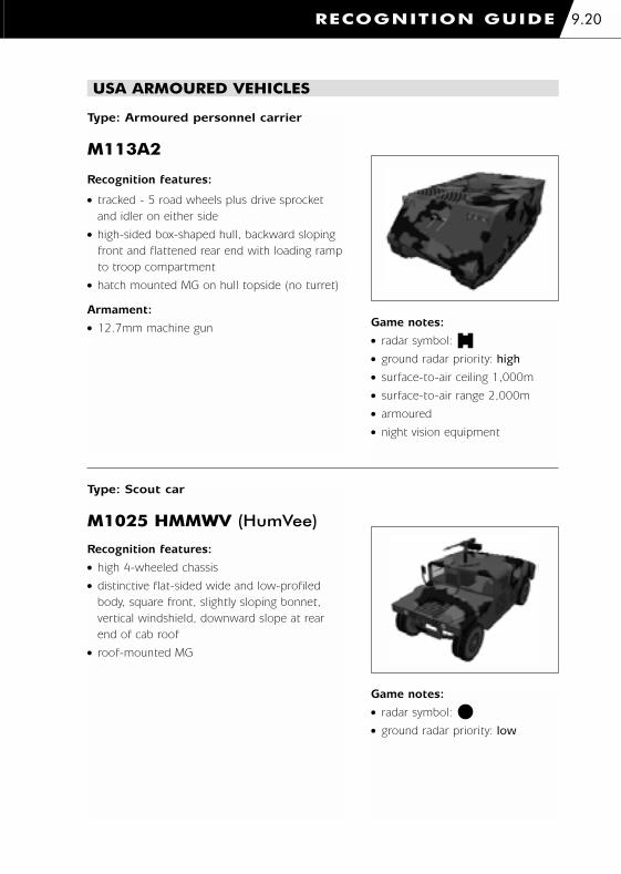
RECOGNITION GUIDE 9.20
USA ARMOURED VEHICLES
Type: Armoured personnel carrier
M113A2
Recognition features:
� tracked - 5 road wheels plus drive sprocket
and idler on either side
� high-sided box-shaped hull, backward sloping
front and flattened rear end with loading ramp
to troop compartment
� hatch mounted MG on hull topside (no turret)
Armament:
� 12.7mm machine gunGame notes:
� radar symbol:
� ground radar priority: high
� surface-to-air ceiling 1,000m
� surface-to-air range 2,000m
� armoured
� night vision equipment
Type: Scout car
M1025 HMMWV (HumVee)
Recognition features:
� high 4-wheeled chassis
� distinctive flat-sided wide and low-profiled
body, square front, slightly sloping bonnet,
vertical windshield, downward slope at rear
end of cab roof
� roof-mounted MG
Game notes:
� radar symbol:
� ground radar priority: low
1036 EE-CH Manual - Chap 9 23/3/00 12:52 pm Page 9.20

RECOGNITION GUIDE9.21
USA SELF-PROPELLED ARTILLERY
Type: Artillery (howitzer)
M109A2 (155mm)Recognition features:
� tracked - 7 road wheels plus drive sprocket and
idler on either side, no side-skirts over tracks
� wide angular hull with bevelled nose section
and downward sloping top at front, flattened
rear with hull access door and stowed
entrenching ‘spades’
� large flat-topped turret centred aft with sloping
curved front and flat sides, thermal sighting
turret and hatch-mounted MG atop, flattened
rear end with projecting stowage
box and racks
� very long high calibre main gun extending
well forward of hull front with large
open-sided muzzle
Armament:
� 155mm howitzer � 12.7mm machine gun
Game notes:
� radar symbol:
� ground radar priority: medium
� surface-to-air ceiling 1,000m
� surface-to-air range 2,000m
� armoured
� night vision equipment
Type: Multiple rocket systems
M270 MLRS (227mm)Recognition features:
� tracked - 6 road wheels plus drive sprocket
and idler on either side, no side-skirts
over tracks
� box-shaped cab section at front with backward
sloping front-face and protective louvres over
windows, rear flatbed platform for launcher
� large box-shaped turret-mounted multiple
rocket launcher stowed horizontally at rear,
turned and pitched to firing position
Armament:
� 227mm rockets
Game notes:
� radar symbol:
� ground radar priority: low
1036 EE-CH Manual - Chap 9 23/3/00 12:52 pm Page 9.21

RECOGNITION GUIDE 9.22
USA AIR DEFENCE VEHICLES
Type: AAA
M163 VulcanRecognition features:
� tracked - 5 road wheels plus drive sprocket
and idler on either side
� high-sided box-shaped hull, backward sloping
front with bulged section, box-shaped bulges
along upper sides, flattened rear end
� small circular turret with sloping sides and flat
open top, small side-mounted radar dish,
distinctive multi-barrelled cannon on pivoting
‘skeleton’ mount
Armament:
� 20mm cannon
Game notes:
� radar symbol:
� ground radar priority: high
� surface-to-air ceiling 1,000m
� surface-to-air range 2,000m
� armoured
� night vision equipment
� range-only radar
Type: SAM
M1037 AvengerRecognition features:
� high 4-wheeled chassis
� distinctive flat-sided wide and low-profiled
body, square front, slightly sloping bonnet,
vertical windshield to cut-short cab, flatbed
launcher platform to rear
� platform-mounted box-shaped sloping-top
turret with pivoting side-mounted rectangular
rocket launchers
Armament:
� FIM-92A Stinger IR guided
surface-to-air missiles
Game notes:
� radar symbol:
� ground radar priority: high
� surface-to-air ceiling 3,000m
� surface-to-air range 5,000m
� night vision equipment
1036 EE-CH Manual - Chap 9 23/3/00 12:53 pm Page 9.22
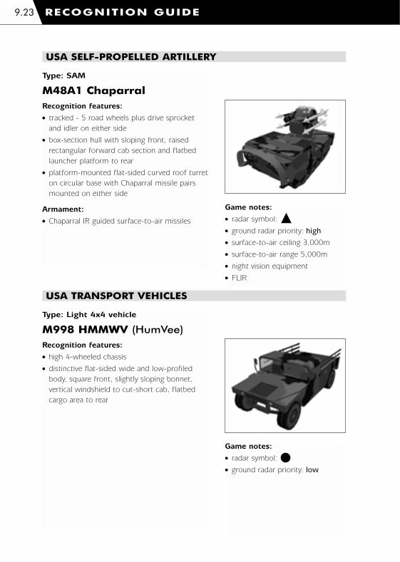
RECOGNITION GUIDE9.23
USA SELF-PROPELLED ARTILLERY
Type: SAM
M48A1 ChaparralRecognition features:
� tracked - 5 road wheels plus drive sprocket
and idler on either side
� box-section hull with sloping front, raised
rectangular forward cab section and flatbed
launcher platform to rear
� platform-mounted flat-sided curved roof turret
on circular base with Chaparral missile pairs
mounted on either side
Armament:
� Chaparral IR guided surface-to-air missiles
Game notes:
� radar symbol:
� ground radar priority: high
� surface-to-air ceiling 3,000m
� surface-to-air range 5,000m
� night vision equipment
� FLIR
Type: Light 4x4 vehicle
M998 HMMWV (HumVee)Recognition features:
� high 4-wheeled chassis
� distinctive flat-sided wide and low-profiled
body, square front, slightly sloping bonnet,
vertical windshield to cut-short cab, flatbed
cargo area to rear
Game notes:
� radar symbol:
� ground radar priority: low
USA TRANSPORT VEHICLES
1036 EE-CH Manual - Chap 9 23/3/00 12:53 pm Page 9.23

RECOGNITION GUIDE 9.24
USA TRANSPORT VEHICLES
Type: Utility vehicle (truck)
M923A1 “Big Foot” Recognition features:
� high 6-wheeled truck chassis - 2 wheels in
front, 4 at rear
� large flat radiator grille with integral headlights,
flat tapering bonnet, box-shaped cab with
vertical windshield, angled mud guards over
front wheels
� high sided canvas covered cargo area to rear
Game notes:
� radar symbol:
� ground radar priority: low
Type: Fuel tanker
M978 (HEMTT)Recognition features:
� high 8-wheeled chassis - 2 pairs of 4 wheels
� distinctive forward-projecting cab with steeply
angled large flat windshield and underside,
narrow rectangular section behind cab with
side-mounted spare wheel
� large curved-sided flat-topped fuel tank to rear
and adjoining downward angled curved rear
end section
Game notes:
� radar symbol:
� ground radar priority: low
1036 EE-CH Manual - Chap 9 23/3/00 12:53 pm Page 9.24

RECOGNITION GUIDE9.25
USA WARSHIPS
Type: Amphibious assault ship
Tarawa ClassRecognition features:
� wide and high-sided box-section hull, long
bow, square stern section
� continuous flight deck
� port side outboard aircraft lift, stern inboard
aircraft lift, large stern water-line loading door
� long narrow rectangular starboard side
superstructure, large forward-mounted lattice
mast and aft-mounted structures atop
� two storey bridge
� large deck-side crane
Armament:
� 25mm cannons
� Sea Sparrow radar guided
surface-to-air missiles
Game notes:
� radar symbol:
� ground radar priority: high
� surface-to-air ceiling 5,000m
� surface-to-air range 1,0000m
� air search radar
Type: Frigate
Oliver Hazard Perry ClassRecognition features:
� slender low-profile hull with sharp high-sided
bow, square inward sloping shallow stern
� long high-sided box-section superstructure
forward raised bridge section, small spherical
radome atop
� tall central lattice mast with large outboard
aerials, shorter forward mast with large
rectangular radar dish atop
� small forward deck gun position on
circular base
� aft deck-level helicopter landing pad
Armament:
� 76mm guns
� SM-1MR Standard radar guided
surface-to-air missiles
Game notes:
� radar symbol:
� ground radar priority: high
� surface-to-air ceiling 5,000m
� surface-to-air range 10,000m
� air search radar
1036 EE-CH Manual - Chap 9 23/3/00 12:53 pm Page 9.25

RECOGNITION GUIDE 9.26
USA WARSHIPS
Type: Landing craft
Tarawa Landing CraftRecognition features:
� flat rectangular hull with squarely angled-in
bow and stern, raised gusseted sides to
cargo deck
� hinged bow loading ramp, twin crane
booms astern
� narrow box-shaped superstructure
on starboard side cargo deck, single
pole-mounted radar antenna
Game notes:
� radar symbol:
� ground radar priority: low
Type: Hovercraft
LCACRecognition features:
� rectangular flat-bed hull, widely projecting
all-round inflatable skirt with square corners
� long and narrow deck-side superstructures
with top-mounted engine intakes/exhausts
� hinging bow and stern loading ramps
� prop-shafts to aft-mounted twin 5-bladed
propellers in circular enclosures with rudder
planes attached
Game notes:
� radar symbol:
� ground radar priority: low
1036 EE-CH Manual - Chap 9 23/3/00 12:53 pm Page 9.26

Type: Attack
Mi-28N Havoc-BRecognition features:
� 5-bladed main rotor with
spherical radome, 4-bladed ‘X’
shaped tail rotor
� tandem ‘stepped’ separate
cockpit arrangement
� nose-mounted radome with FLIR
turret underneath
� rounded engine nacelles with
downward pointing rearward
exhaust outlets
� stub-wings (downward sloping)
with pylons and wing-tip
ECM pods
� chin-mounted cannon turret with
ammo panniers
� asymmetrical tail plane
arrangement
� fixed undercarriage and tail wheel
Armament:
� 30mm cannon (both armour
piercing and high explosive
rounds)
� Igla-V IR guided air-to-air missiles
� Ataka radio command guided
anti-tank missiles
� 80mm unguided rockets
� 130mm unguided rockets
� GSh-23L 23mm cannon pods
Decoys:
� Chaff
� Flares
RECOGNITION GUIDE9.27
RUSSIAN COMBAT HELICOPTERS
Game notes:
� radar symbol:
� ground radar priority: medium
1036 EE-CH Manual - Chap 9 23/3/00 12:53 pm Page 9.27

Ka-50 HokumRecognition features:
� twin 3-bladed co-axial main
rotors (no tail rotor), mast-
mounted 'mini' radome
� single seat cockpit with angular
flat armour glass canopy
� narrow angular cockpit section
blending to smoothly sharpened
nose section with chin-mounted
fixed sight on flattened
underside, rounded square-
section tail boom with even taper
to point at rear
� rounded engine nacelles each
side of upper fuselage
immediately aft of cockpit,
domed dust filters to air intakes
� distinctive tail configuration -
angular tail fin and tail plane with
endplate fins
� enlarged stub wings with
weapons pylons and wing tip
ECM pods
� side-mounted 30mm cannon
� retractable tricycle undercarriage
Armament:
� 30mm cannon (both armour
piercing and high explosive
rounds)
� Igla-V IR guided air-to-air missiles
� Vikhr laser guided anti-tank
missiles
� 80mm unguided rockets
� 130mm unguided rockets
� GSh-23L 23mm cannon pods
Decoys:
� chaff
� flares
RECOGNITION GUIDE 9.28
RUSSIAN COMBAT HELICOPTERS
Game notes:
� radar symbol:
� ground radar priority: medium
Type: Attack
1036 EE-CH Manual - Chap 9 23/3/00 12:53 pm Page 9.28

RECOGNITION GUIDE9.29
Ka-52 Hokum-BRecognition features:
� twin 3-bladed co-axial main
rotors (no tail rotor), mast-
mounted 'mini' radome
� twin seat side-by side cockpit
with flat armour windshield and
curved 'gull-wing' style upward
opening canopy doors
� smoothly sculpted forward
fuselage section with rounded
nose, rounded square-section tail
boom with even taper to point
at rear
� rounded engine nacelles each side
of upper fuselage immediately aft
of cockpit, domed dust filters to
air intakes
� distinctive tail configuration -
angular tail fin and tail plane with
endplate fins
� nose-mounted cylindrical FLIR
turret, spherical SAMSHIT turret
above cockpit rear
� enlarged stub wings with
weapons pylons and wing tip
ECM pods
� side-mounted 30mm cannon
� retractable tricycle undercarriage
Armament:
� 30mm cannon (both armour
piercing and high explosive
rounds)
� Igla-V IR guided air-to-air missiles
� Vikhr laser guided anti-tank
missiles
� 80mm unguided rockets
� 130mm unguided rockets
� GSh-23L 23mm cannon pods
RUSSIAN COMBAT HELICOPTERS
Decoys:
� chaff
� flares
Game notes:
� radar symbol:
� ground radar priority: medium
Type: Reconnaissance/attack
1036 EE-CH Manual - Chap 9 23/3/00 12:53 pm Page 9.29

RECOGNITION GUIDE 9.30
Type: Attack/assault
Mi-24D HindRecognition features:
� 5-bladed main rotor, 3-bladed
tail rotor
� tandem stepped cockpits with
domed canopies
� tall and narrow appearance to
main fuselage
� hinged loading doors on either
side of main cabin
� IR suppressors fitted to engine
exhaust outlets
� sharply downward angled stub
wings with weapons pylons and
down turned wing-tips
� chin-mounted gun-turret and
sight/radar mounts
� retractable tricycle undercarriage
Armament:
� 12.7mm Gatling gun
� AT-6 Spiral radio command
guided anti-tank missiles
� 57mm unguided rockets
� 80mm unguided rockets
Decoys:
� chaff
� flares
RUSSIAN COMBAT HELICOPTERS
Game notes:
� radar symbol:
� ground radar priority: medium
1036 EE-CH Manual - Chap 9 23/3/00 12:53 pm Page 9.30
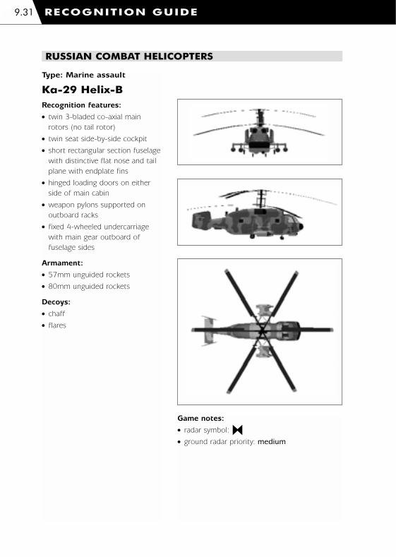
Type: Marine assault
Ka-29 Helix-BRecognition features:
� twin 3-bladed co-axial main
rotors (no tail rotor)
� twin seat side-by-side cockpit
� short rectangular section fuselage
with distinctive flat nose and tail
plane with endplate fins
� hinged loading doors on either
side of main cabin
� weapon pylons supported on
outboard racks
� fixed 4-wheeled undercarriage
with main gear outboard of
fuselage sides
Armament:
� 57mm unguided rockets
� 80mm unguided rockets
Decoys:
� chaff
� flares
RUSSIAN COMBAT HELICOPTERS
Game notes:
� radar symbol:
� ground radar priority: medium
RECOGNITION GUIDE9.31
1036 EE-CH Manual - Chap 9 23/3/00 12:53 pm Page 9.31

RECOGNITION GUIDE 9.32
Type: Medium-lift
Mi-17 HipRecognition features:
� 5-bladed main rotor and
3-bladed tail rotor
� twin seat side-by-side cockpit
inside glazed nose
� long rounded main fuselage and
slender tail boom
� rear fuselage has ‘clam shell’
cargo hold doors
� IR suppressor fitted to engine
exhaust outlets
� weapon pylons supported on
outboard racks
� fixed tricycle undercarriage
with outboard struts supporting
main wheels
Armament:
� 57mm unguided rockets
� 80mm unguided rockets
Decoys:
� chaff
� flares
RUSSIAN TRANSPORT HELICOPTERS
Game notes:
� radar symbol:
� ground radar priority: medium
1036 EE-CH Manual - Chap 9 23/3/00 12:53 pm Page 9.32
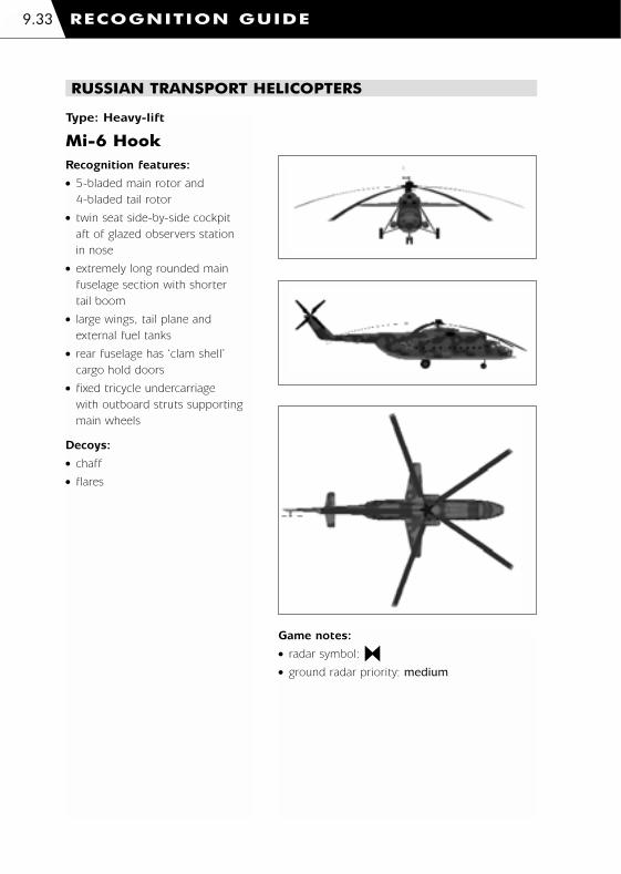
Type: Heavy-lift
Mi-6 HookRecognition features:
� 5-bladed main rotor and
4-bladed tail rotor
� twin seat side-by-side cockpit
aft of glazed observers station
in nose
� extremely long rounded main
fuselage section with shorter
tail boom
� large wings, tail plane and
external fuel tanks
� rear fuselage has ‘clam shell’
cargo hold doors
� fixed tricycle undercarriage
with outboard struts supporting
main wheels
Decoys:
� chaff
� flares
RUSSIAN TRANSPORT HELICOPTERS
Game notes:
� radar symbol:
� ground radar priority: medium
RECOGNITION GUIDE9.33
1036 EE-CH Manual - Chap 9 23/3/00 12:53 pm Page 9.33

RECOGNITION GUIDE 9.34
Type: Close air support
Su-25 FrogfootRecognition features:
� high-wing, swept leading
edge, square trailing edge,
wing-tip pods
� single tall tail fin with smaller aft
upward canted tail plane on aft
projecting boom
� short sloping nose and canopy,
flattened fuselage sides and
bottom, rounded engine nacelles
with aft projecting circular outlets
� many under-wing weapon
hard points and large nose
mounted cannon
� fully retractable tricycle
undercarriage
Armament:
� 30mm cannon
� AA-8A Aphid IR guided
air-to-air missiles
� 80mm unguided rockets
Decoys:
� chaff
� flares
RUSSIAN COMBAT AIRCRAFT
Game notes:
� radar symbol:
� ground radar priority: medium
1036 EE-CH Manual - Chap 9 23/3/00 12:53 pm Page 9.34
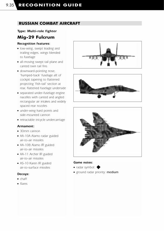
RECOGNITION GUIDE9.35
Type: Multi-role fighter
Mig-29 FulcrumRecognition features:
� low-wing, swept leading and
trailing edges, wings blended
to fuselage
� all-moving swept tail plane and
canted twin tail fins
� downward-pointing nose,
‘humped-back’ fuselage aft of
cockpit tapering to flattened
projecting ‘fish-tail’ section at
rear, flattened fuselage underside
� separated under-fuselage engine
nacelles with canted and angled
rectangular air intakes and widely
spaced rear nozzles
� under-wing hard points and
side-mounted cannon
� retractable tricycle undercarriage
Armament:
� 30mm cannon
� AA-10A Alamo radar guided
air-to-air missiles
� AA-10B Alamo IR guided
air-to-air missiles
� AA-11 Archer IR guided
air-to-air missiles
� AS-10 Karen IR guided
air-to-surface missiles
Decoys:
� chaff
� flares
RUSSIAN COMBAT AIRCRAFT
Game notes:
� radar symbol:
� ground radar priority: medium
1036 EE-CH Manual - Chap 9 23/3/00 12:54 pm Page 9.35

RECOGNITION GUIDE 9.36
Yak-41 FreestyleRecognition features:
� high-wing, swept leading edge,
square trailing edge with slight
sweep along outer section,
wing-tip pods
� compact square-sided fuselage
with angled side air intakes and
short nose with ‘up-front’ cockpit
� distinctive twin tail booms and
canted fins, cutaway for
extendable thrust vectoring
engine nozzle
� under-wing hard-points
� retractable tricycle undercarriage
Armament:
� 30mm cannon
� AA-8A Aphid IR guided
air-to-air missiles
� 80mm unguided rockets
Decoys:
� chaff
� flares
RUSSIAN COMBAT AIRCRAFT
Game notes:
� radar symbol:
� ground radar priority: medium
Type: Carrier-borne attack
1036 EE-CH Manual - Chap 9 23/3/00 12:54 pm Page 9.36

Su-33 FlankerRecognition features:
� low-wing, swept leading
and trailing edge, blended
to fuselage, swept canard
foreplanes
� downward angled forward
fuselage with enlarged bulbous
nose section, ‘humped-back’
central fuselage tapering to
flattened projecting ‘tail-sting’
at rear
� swept tail plane and twin
vertical tail fins
� separated under-fuselage engine
nacelles with canted and angled
rectangular air intakes and large
widely spaced rear nozzles
� under-wing and fuselage
hard-points with wing-tip
missile mounts
� retractable tricycle undercarriage
Armament:
� 30mm cannon
� AA-8A Aphid IR guided
air-to-air missiles
� AA-8B Aphid radar guided
air-to-air missiles
� AA-10A Alamo radar guided
air-to-air missiles
� AA-10B Alamo IR guided
air-to-air missiles
� AS-14 Kedge laser guided
air-to-surface missiles
Decoys:
� chaff
� flares
RUSSIAN COMBAT AIRCRAFT
Game notes:
� radar symbol:
� ground radar priority: medium
RECOGNITION GUIDE9.37
Type: Carrier-borne interceptor
1036 EE-CH Manual - Chap 9 23/3/00 12:54 pm Page 9.37

RECOGNITION GUIDE 9.38
An-12B CubRecognition features:
� 4 turboprop engines with 4-
bladed propellers on under-wing
nacelles
� high-wing configuration with
swept leading edge and
downward canted wing tip
sections
� large angled tail fin incorporating
tail gun turret, tail plane set well
aft
� large circular-sectioned fuselage
tapering to broadly flattened tail
boom at rear, rounded sponsons
to lower fuselage centre section
� smoothly rounded nose section
tapering to glazed observation
turret below wrap-around cockpit
glazing, chin-mounted radome
feature
� large inward hinging cargo doors
to rear under sloping tail
underside
� retractable undercarriage with 4
fixed main wheels arranged 2
pairs at rear and twin steerable
nose wheels
Decoys:
� chaff
� flares
RUSSIAN TRANSPORT AIRCRAFT
Game notes:
� radar symbol:
� ground radar priority: medium
Type: Medium-lift
1036 EE-CH Manual - Chap 9 23/3/00 12:54 pm Page 9.38
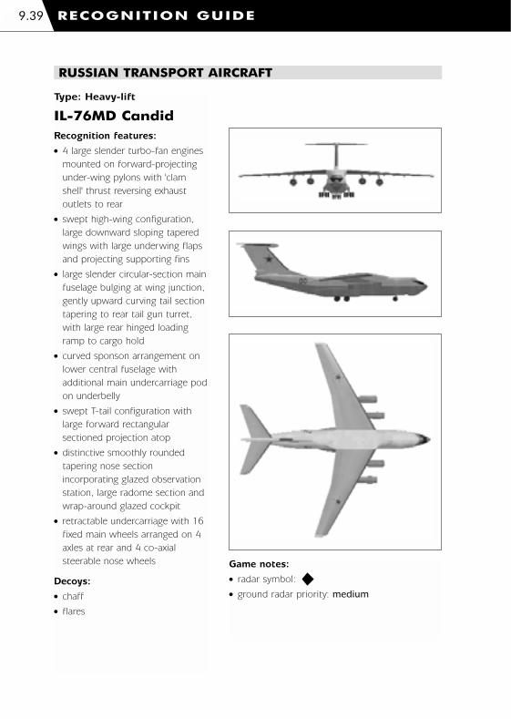
RECOGNITION GUIDE9.39
IL-76MD CandidRecognition features:
� 4 large slender turbo-fan engines
mounted on forward-projecting
under-wing pylons with 'clam
shell' thrust reversing exhaust
outlets to rear
� swept high-wing configuration,
large downward sloping tapered
wings with large underwing flaps
and projecting supporting fins
� large slender circular-section main
fuselage bulging at wing junction,
gently upward curving tail section
tapering to rear tail gun turret,
with large rear hinged loading
ramp to cargo hold
� curved sponson arrangement on
lower central fuselage with
additional main undercarriage pod
on underbelly
� swept T-tail configuration with
large forward rectangular
sectioned projection atop
� distinctive smoothly rounded
tapering nose section
incorporating glazed observation
station, large radome section and
wrap-around glazed cockpit
� retractable undercarriage with 16
fixed main wheels arranged on 4
axles at rear and 4 co-axial
steerable nose wheels
Decoys:
� chaff
� flares
RUSSIAN TRANSPORT AIRCRAFT
Game notes:
� radar symbol:
� ground radar priority: medium
Type: Heavy-lift
1036 EE-CH Manual - Chap 9 23/3/00 12:54 pm Page 9.39

RECOGNITION GUIDE 9.40
RUSSIAN ARMOURED VEHICLES
Type: Main battle tank
T-80URecognition features:
� tracked - 6 road wheels plus drive sprocket and
idler on either side
� long and low flat-sided hull with front and rear
splashers curving down over track ends, front
top-side of hull slopes down between side-skirts,
distinctive pair of fuel barrels mounted on rear
� distinctive low circular domed turret with hatch
mounted MG and stowed snorkel on brackets
at rear
� long high calibre main gun barrel overhangs
hull front
Armament:
� 125mm gun � 12.7mm machine gun
� AT-11 Sniper laser beam riding anti-tank missiles
Decoys:
� smoke grenades
Game notes:
� radar symbol:
� ground radar priority: medium
� surface-to-air ceiling 1,000m
� surface-to-air range 2,000m
� armoured
� night vision equipment
Type:Infantry fighting vehicle
BMP-2Recognition features:
� tracked - 6 road wheels plus drive sprocket
and idler on either side
� angular low-profile hull with sloping underside
and sharply pointed leading edge, flattened
rear with bulged access doors, curved-ended
splashers to tracks projecting along sides
� small circular turret with sloping sides and
flat top offset to aft, long slender low calibre
main gun barrel and turret mounted tubular
missile launcher
Armament:
� 30mm cannon
� AT-5 Spandrel radar guided anti-tank missiles
Decoys:
� smoke grenades
Game notes:
� radar symbol:
� ground radar priority: high
� surface-to-air ceiling 2,000m
� surface-to-air range 4,000m
� armoured
� night vision equipment
1036 EE-CH Manual - Chap 9 23/3/00 12:54 pm Page 9.40

RUSSIAN ARMOURED VEHICLES
RECOGNITION GUIDE9.41
Type: Infantry fighting vehicle
BMP-3Recognition features:
� tracked - 6 road wheels plus drive sprocket and
idler on either side
� high-sided box shaped hull, sloping underside to
front with pointed leading edge and flattened
rear end, troop compartment main access doors
on rear topside and rear end of hull
� small circular flat-topped turret, high calibre main
gun barrel with box-shaped laser sight mounted
over base and side-mounted co-axial cannon
Armament:
� 100mm gun � 30mm cannon
� AT-10 Stabber laser beam riding
anti-tank missiles
Decoys:
� smoke grenades
Game notes:
� radar symbol:
� ground radar priority: high
� surface-to-air ceiling 1,000m
� surface-to-air range 2,000m
� armoured
� night vision equipment
Type: Armoured personnel carrier
BTR-80Recognition features:
� high 8-wheeled chassis, 2 pairs of 4 wheels
� angular long narrow hull with sloping
underside to front, flattened rear end and
sloped upper sides with angular wheel
arches below
� very small circular flat-topped MG
mounted turret
Armament:
� 14.5mm machine gun
Decoys:
� smoke grenades
Game notes:
� radar symbol:
� ground radar priority: medium
� surface-to-air ceiling 1,000m
� surface-to-air range 2,000m
� armoured
� night vision equipment
1036 EE-CH Manual - Chap 9 23/3/00 12:54 pm Page 9.41
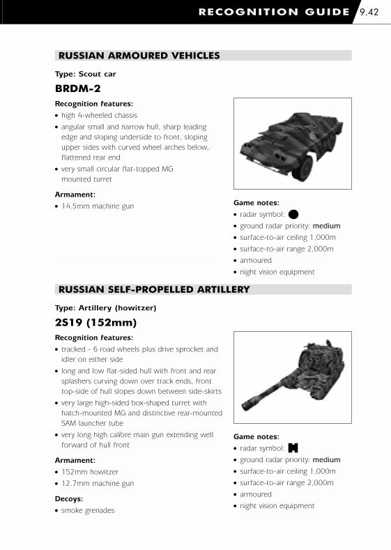
RECOGNITION GUIDE 9.42
RUSSIAN ARMOURED VEHICLES
Type: Scout car
BRDM-2Recognition features:
� high 4-wheeled chassis
� angular small and narrow hull, sharp leading
edge and sloping underside to front, sloping
upper sides with curved wheel arches below,
flattened rear end
� very small circular flat-topped MG
mounted turret
Armament:
� 14.5mm machine gun Game notes:
� radar symbol:
� ground radar priority: medium
� surface-to-air ceiling 1,000m
� surface-to-air range 2,000m
� armoured
� night vision equipment
Type: Artillery (howitzer)
2S19 (152mm)Recognition features:
� tracked - 6 road wheels plus drive sprocket and
idler on either side
� long and low flat-sided hull with front and rear
splashers curving down over track ends, front
top-side of hull slopes down between side-skirts
� very large high-sided box-shaped turret with
hatch-mounted MG and distinctive rear-mounted
SAM launcher tube
� very long high calibre main gun extending well
forward of hull front
Armament:
� 152mm howitzer
� 12.7mm machine gun
Decoys:
� smoke grenades
Game notes:
� radar symbol:
� ground radar priority: medium
� surface-to-air ceiling 1,000m
� surface-to-air range 2,000m
� armoured
� night vision equipment
RUSSIAN SELF-PROPELLED ARTILLERY
1036 EE-CH Manual - Chap 9 23/3/00 12:54 pm Page 9.42

RUSSIAN SELF-PROPELLED ARTILLERY
RECOGNITION GUIDE9.43
Type: Multiple rocket systems
BM-21 Grad MRS (122mm)Recognition features:
� high 6-wheeled truck chassis - 2 wheels at
front, 4 at rear
� low wide radiator grille, smooth curved
tapering bonnet and short upright cab with
backward sloping windshield, vertical faced
mud guards over front wheels with integral
headlights, flatbed platform behind with
launcher turret over rear axle
� box-shaped grouped rocket tubes stowed
on turret at rear, turned and pitched to
firing position
Armament:
� 122mm rockets
Game notes:
� radar symbol:
� ground radar priority: low
Type: SAM
SA-13 GopherRecognition features:
� tracked - 6 road wheels plus drive sprocket
and idler on either side, no side-skirts
� long low-profile flat-topped hull with tapering
cab sides and sloping top/underside to front,
box-shaped side-mounted stowage lockers
along upper sides, flattened rear end
� centred circular turret mount for launcher arm
with side-mounted box-section rocket
launchers, stowed laid flat on hull top and
pivoted on arm to firing position
Armament:
� SA-13 Gopher IR guided surface-to-air missiles
Game notes:
� radar symbol:
� ground radar priority: high
� surface-to-air ceiling 3,000m
� surface-to-air range 5,000m
� armoured
� night vision equipment
� Flat Box passive radar
RUSSIAN AIR DEFENCE VEHICLES
1036 EE-CH Manual - Chap 9 23/3/00 12:55 pm Page 9.43

RECOGNITION GUIDE 9.44
RUSSIAN AIR DEFENCE VEHICLES
Type: SAM/AAA
SA-19 GrisonRecognition features:
� tracked - 6 road wheels plus drive sprocket and
idler on each side, no side-skirts
� box-section hull, downward sloping front,
flattened and slightly inward sloping rear end
� long and narrow rectangular main turret section
over-hanging circular turret base at rear, frontal
radome mounting, curved rectangular radar dish
mounted on elevated section at turret rear top
� twin-barreled cannon and quad SAM tubes
mounted on either turret side
Armament:
� 4x30mm cannons
� SA-19 Grison radio command guided
surface-to-air missiles
Game notes:
� radar symbol:
� ground radar priority: high
� surface-to-air ceiling 4,000m
� surface-to-air range 8,000m
� armoured
� night vision equipment
� surveillance and tracking radar
Type: Light 4x4 vehicle
UAZ-469BRecognition features:
� high 4-wheeled chassis,
� small compact appearance, distinctive rounded
bonnet, headlights and radiator grille,
backward sloping windshield, canvas roof
Game notes:
� radar symbol:
� ground radar priority: low
RUSSIAN TRANSPORT VEHICLES
1036 EE-CH Manual - Chap 9 23/3/00 12:55 pm Page 9.44

RUSSIAN TRANSPORT VEHICLES
RECOGNITION GUIDE9.45
Type: Utility vehicle (truck)
Ural-4320Recognition features:
� high 6-wheeled truck chassis - 2 wheels in
front, 4 at rear
� low wide radiator grille, smooth curved tapering
bonnet and short upright cab with backward
sloping windshield, vertical faced mud guards
over front wheels with integral headlights
� high sided canvass covered cargo area to rear
Game notes:
� radar symbol:
� ground radar priority: low
Type: Fuel tanker
Ural-4320 Fuel TankerRecognition features:
� high 6-wheeled truck chassis - 2 wheels in
front, 4 at rear
� low wide radiator grille, smooth curved
tapering bonnet and short upright cab
with backward sloping windshield, vertical
faced mud guards over front wheels with
integral headlights
� squat flat-sided curved-topped fuel tank
at rear Game notes:
� radar symbol:
� ground radar priority: low
1036 EE-CH Manual - Chap 9 23/3/00 12:55 pm Page 9.45
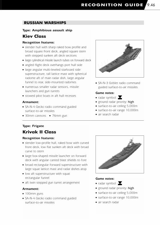
RECOGNITION GUIDE 9.46
RUSSIAN WARSHIPS
Type: Amphibious assault ship
Kiev ClassRecognition features:
� slender hull with sharp raked bow profile and
broad square front deck, angled square stern
with stepped sunken aft deck sections
� large cylindrical missile launch tubes on forward deck
� angled flight deck overhangs port hull side
� large angular multi-leveled starboard side
superstructure, tall lattice mast with spherical
radome aft of main radar dish, large angular
funnel to rear, side-mounted radomes
� numerous smaller radar sensors, missile
launchers and gun turrets
� stowed pilot boats in aft hull recesses
Armament:
� SA-N-4 Gecko radio command guided
surface-to-air missiles
� 30mm cannons � 76mm gun
� SA-N-3 Goblet radio command
guided surface-to-air missiles
Game notes:
� radar symbol:
� ground radar priority: high
� surface-to-air ceiling 5,000m
� surface-to-air range 10,000m
� air search radar
Type: Frigate
Krivak II ClassRecognition features:
� slender low-profile hull, raked bow with curved
front deck, low flat sunken aft deck with broad
curve to stern
� large box-shaped missile launcher on forward
deck with angular canted blast shields to fore
� broad rectangular forward superstructure with
large squat lattice mast and radar dishes atop
� low aft superstructure with squat
rectangular funnel
� aft twin stepped gun turret arrangement
Armament:
� 100mm guns
� SA-N-4 Gecko radio command guided
surface-to-air missiles
Game notes:
� radar symbol:
� ground radar priority: high
� surface-to-air ceiling 5,000m
� surface-to-air range 10,000m
� air search radar
1036 EE-CH Manual - Chap 9 23/3/00 12:55 pm Page 9.46

RUSSIAN WARSHIPS
RECOGNITION GUIDE9.47
Type: Hovercraft
AISTRecognition features:
� long and wide high-sided hull with curved
upper edge and rounded overhanging bow
section over loading ramp below, high-sided
all-round inflatable skirt with enlarged curved
bulge under bow door
� twin forward-mounted gun turrets either
side of bow
� low and wide forward bridge section with
squat lattice mast to rear, large low square
structure amidships
� aft mast-mounted twin pairs of face-to-face
4-blade propeller sets forward of tall twin
tail fins/rudders
Armament:
� 30mm cannons
Game notes:
� radar symbol:
� ground radar priority: high
� surface-to-air ceiling 1,000m
� surface-to-air range 2,000m
1036 EE-CH Manual - Chap 9 23/3/00 12:55 pm Page 9.47

10. APPENDICES
1036 EE-CH Manual - Chapt 10 23/3/00 12:56 pm Page 1

Trouble shooting
Updates
For latest news and information visit www.razorworks.com
Graphics Drivers
If you are experiencing problems with Comanche Hokum graphics, we have included some
graphics cards drivers for you to install. These are located on your CD in the directory called
'Graphics Drivers\Drivers'.
Please note that these drivers should only be used if you have problems with your graphics
card. Whilst we have taken care to ensure that the drivers are the latest versions available,
they are being constantly updated by the graphics card manufacturers.
These drivers are not necessarily from the card manufacturers, but from the chipset
manufacturers, so it is possible you may lose features added by your originally installed drivers.
To get the latest chipset drivers you will need to visit the following websites:-
For 3Dfx drivers: www.3dfx.com
For 3Dlabs drivers: www.3dlabs.com
For ATI drivers: www.atitech.ca
For Chromatic Research drivers: www.chromatic.com
For Matrox drivers: www.matrox.com
For NVIDIA drivers: www.nvidia.com
For Real3D drivers: www.real3d.com
For Rendition drivers: www.rendition.com
For S3 drivers: www.s3.com
Re-Installing
If you re-install Comanche Hokum on to your PC then please ensure that the previous
installation was completely removed. That is, in addition to un-installing Comanche Hokum
delete the Razorworks\cohokum folder as well.
Cannot Find Comanche Hokum CD
If Comanche Hokum reports that it cannot find the CD then please ensure that you have
closed any CD Player applications that may have captured the CD.
Loading ... "Comms System" Crash
On the rare occurrence that the program hangs while initialising the ‘Comms System’ then
you will need to reboot your PC.
APPENDICES10.1
1036 EE-CH Manual - Chapt 10 23/3/00 12:56 pm Page 10.1

‘Sticky’ Keys
Occasionally you may experience problems with 'sticky' keys.
For example, the torque value may continue to rise or fall even though you have released the
collective keys. Pressing and releasing the appropriate key will solve the problem (press Q if
the torque value is continuously rising, or press A if the torque value is continuously falling).
Multiplayer Connection Problems in Windows 98
If your network card uses a Realtek 8029 chipset then you may experience an unstable
connection in Windows 98 (not Windows 95). You can get updated drivers from the Realtek
website (www.realtek.com.tw).
Graphics
If you are experiencing problems with Comanche Hokum graphics then please ensure that
you have the latest drivers for your 3D graphics card.
Comanche Hokum terminates with "Unable to find a 3D graphics card ..."
Comanche Hokum requires that your PC has a 3D graphics card. If the program terminates
with the message "Unable to find a 3D graphics card. Please ensure you have the latest
drivers for your 3D card and have installed DirectX 7" then please ensure that you have a
3D graphics card with the appropriate drivers.
PowerVR
Comanche Hokum does not support some older PowerVR cards. A PowerVR card may be
present if the program terminates with the message "Unable to create Zbuffer surface:
DDERR_NOZBUFFERHW".
RivaTNT
3D graphics cards which use the RivaTNT chipset must have 'VSYNC' enabled otherwise
flickering will occur. This may occur on other chipsets which have a switchable 'VSYNC'.
Riva128
The Riva128 chipset exhibits a graphical artefact in that the right hand and bottom edges
of the 3D display have a 'dirty' edge. This can be rectified by running the program with the
‘/3dce’ command line option.
Hardware Geometry Acceleration (TnL)
If your graphics card supports geometry acceleration (transformation and lighting – ‘TnL’)
then Comanche Hokum will use this by default. However, more data is required and this
may cause excessive memory paging on some machines. If this occurs then disable the
geometry acceleration using the ‘/notnl’ command line option.
APPENDICES 10.2
1036 EE-CH Manual - Chapt 10 23/3/00 12:56 pm Page 10.2

TADS and EOS 3D display is missing from MFD page
The TADS and EOS MFD pages require your 3D card to be able to render a 3D scene to a
texture. Some cards do not support this feature. In which case the 3D display will be absent
from the MFD page. The 3D display will be displayed on the full screen MFD views (use q
and r to see these).
Command Line Options
Comanche Hokum is customisable to some degree by the user. Some flight model, visual
and most communication elements can be altered by passing command line parameters
when launching the game.
Command line parameters can be entered into a DOS box or program shortcut (‘Target’ field).
As an alternative to using command line or shortcuts options, you can specify the
commands you want with the COMANCHE_HOKUM environment variable and SET
command.
For example:-
SET COMANCHE_HOKUM=/cgs:1 /cig:1 /cbar:1000
This can be included in your AUTOEXEC.BAT file.
Visual
Switch Meaning Description
/mfr:n max_frame_rate n = max visual frame rate
(defaults = 30)
Flight Dynamics
Switch Meaning Description
/drbs:n dynamics_retreating_blade_stall n = floating point scaling factor for
RBS effect (default = 1.0)
/drv:n dynamics_rudder_value n = scaling factor for drag on
tail rotation (default = 1.0)
/dra:n dynamics_rudder_acceleration n = scaling factor for tail rotation
acceleration (default = 0.8)
/drd:n dynamics_main_rotor_drag n = scaling factor for drag caused
by main rotor (default = 1.0)
/dtrd:n dynamics_tail_rotor_drag n = scaling factor for drag caused by
tail in forward flight (default = 1.0)
/dczd:n dynamics_cyclic_dead_zone n = percentage dead zone for the
cyclic (default = 0.0)
/vfm:1 vector_flight_model activates viewer or ‘UFO’ flight mode
APPENDICES10.3
1036 EE-CH Manual - Chapt 10 23/3/00 12:56 pm Page 10.3

Graphic Cards
Switch Meaning Description
/3dreset 3d_reset reset screen resolution to 640x480
/3dce 3d_clean_edge cleans up the graphical artefact
exhibited by Riva128 chipsets
/cbt cpu_blit_textures try specifying this option if you
experience slowdowns during rain
/notnl no_transformation_and_lighting disable hardware geometry
acceleration
Sound Cards
Switch Meaning Description
/ns no_sound bypass sound card, useful for
tracking hardware conflicts
Communications
Switch Meaning Description
/ccrs:n comms_connection_receive_size n = Initial guess of campaign data
size. If campaign data is larger then
this can slow things down
(default = 200k)
/cdrs:n comms_data_record_size similar to above…
/cpbs:n comms_pack_buffer_size similar to above…
/cgs:1 comms_guaranteed_send force the comms to use DirectPlay
guaranteed send instead of its own
n = 1 (turn on) n = 0
(turn off – default)
/crls:n comms_resend_list_size n = packet history list size, increase
if client keeps getting kicked out by
server (default = 1000)
/crl:n comms_rerequest_limit n = number of times a client can
re-request the same packet. Increase
this for poor connections
(default = 10)
/cpt:n comms_packet_timer n = time delay in seconds the
comms will wait for a packet before
re-requesting it (default = 5s)
APPENDICES 10.4
1036 EE-CH Manual - Chapt 10 23/3/00 12:56 pm Page 10.4

Communications
Switch Meaning Description
/crt:n comms_resend_timeout n = time comms will wait before
assuming re-requested packets was
lost (default = 2s)
/mur:n max_update_rate n = network frame rate for a server,
n/a for a client (default = 5fps for
TCP/IP, 15fps for IPX)
/cig:1 comms_interpolate_gunships program will interpolate a players
helicopter position for smoother
visuals n = 0 (off / default) n = 1 (on)
/cvc:1 comms_validate_connection removes dead player husks when
client crashes
n = 0 (off / default) n = 1 (on)
/cto:n comms_time_out the amount of time to wait before
removing dead player husks
n = 0 (off / default) n = 1 (on)
/cist:n comms_initial_sleep_time sets the length of time
(in milliseconds) the program will
wait before sending packets
(default = 500)
/cpt:n comms packet timer sets the length of time (in seconds)
the program will wait for a packet
before re-requesting it (default = 5)
/crto:n comms_resend_timeout sets the length of time (in seconds)
the program will wait for a
re-requested packet before asking
for it again (default = 1)
Miscellaneous
Switch Meaning Description
/goto:1 planner_goto_button activates ‘GOTO’ teleport button on
the campaign map
/psr:n player_start_rank n = start rank for new pilots
/uit:n user_invulnerable_time invulnerable time allowed after
entering the cockpit
(default = 5 seconds)
APPENDICES10.5
1036 EE-CH Manual - Chapt 10 23/3/00 12:56 pm Page 10.5

Notes
APPENDICES 10.6
1036 EE-CH Manual - Chapt 10 23/3/00 12:56 pm Page 10.6

Acronyms
AAA Anti-Aircraft Artillery (‘Triple A’)
AFAPD Air-Force Applications
Program Development
AFTDS Advanced Field Artillery
Tactical Data System
AGM Air to Ground Missile
AP Armour Piercing
APC Armoured Personnel Carrier
APU Auxiliary Power Unit
ASE Air Survivability Equipment
ATGM Anti-Tank Guided Missile
BAI Battlefield Air Interdiction
BARCAP Barrier Combat Air Patrol
BDA Battle Damage Assessment
CAP Combat Air Patrol
CAS Close Air Support
CMW Centimetric Wave
CP/G Co-Pilot/Gunner
DTV Daylight TV
DVO Direct View Optics
ECM Electronic Countermeasures
EO Electro Optics
EOS Electro-Optical System
EWS Electronic Warfare Suite
FAC Forward Air Controller
FARP Forward Arming And
Refueling Point
FFAR Folding Fin Aerial Rocket
FLIR Forward Looking Infra-Red
HE High Explosive
HEAT High Explosive Anti-Tank
HEDP High Explosive Dual Purpose
HF High Frequency
HIDSS Helmet Integrated Display
and Sight System
HMS Helmet Mounted Sight
HOCAS Hands On Collective And Stick
HSI Horizontal Situation Indicator
HUD Head Up Display
IDM Improved Data Modem
IFV Infantry Fighting Vehicle
IOC Initial Operating Capability
IR Infra-Red
I-RAMS Integrated Retractable
Munitions System
LLLTV Low Light Level TV
LO Low Observable
LOAL Lock On After Launch
LOBL Lock On Before Launch
LOS Line Of Sight
LZ Landing Zone
MBT Main Battle Tank
MFD Multi-Function Display
MMW Millimeter Wave
MPSM Multi-Purpose Sub-Munitions
MRLS Multiple Rocket Launch System
MTS Marine Tactical Systems
NBC Nuclear Biological Chemical
NOE Nap Of the Earth
NVG Night Vision Goggles
OCA Offensive Counter Air
PNVS Pilot Night Vision Sensor
POV Point Of View
RCS Radar Cross Section
RWR Radar Warning Receiver
SAM Surface to Air Missile
SEAD Suppression of Enemy
Air Defences
TACFIRE TACtical FIRE direction system
TADS Target Acquisition and
Designation System
TOW Tube-Launched,
Optically-tracked, Wire-guided
TSD Tactical Situation Display
TWD Threat Warning Display
VMF Variable Message Format
VSI Vertical Speed Indicator
APPENDICES10.7
1036 EE-CH Manual - Chapt 10 23/3/00 12:56 pm Page 10.7

CreditsRAZORWORKS
Design Team
Kevin Bezant
Carl Edwards
Todd Gibbs
Dave Lomas
James Morris
Dave Proctor
Neil Roberts
Jeff Sheard
Matt Smith
Manual Writing
Nikolai Arturovich
Richard Hawley
Ben Wilkins
Strategy Guide
Richard Hawley
Music
Alex Cable
Voice Scripting
Steve Grimaldi, CW3 US Army (active)
Richard Hawley
Jan Löbzien
Beta Testers
Nigel ‘Hawk’ Doyle
Kurt ‘Froglips’ Giesselman
Christian ‘Enforcer’ Giroux
Richard ‘Flexman’ Hawley
Steve ‘Shodan’ Harper
Jan ‘Blaze’ Löbzien
Bryan ‘Zero G’ den Otter
Matthew ‘LIONPRIDE’ Starace
Artur ‘CEP}I{AHT’ Valitov
Jerome ‘Zulu One’ Zimmermann
EMPIRE INTERACTIVE
Executive Producer
Roger Cheung
Producer
Nick Halstead
Assistant Producer
Danny Rawles
Head of QA
Mike Holton
QA Manager
Darren Thompson
Lead Tester
Iain Riches
Play Testers
John Murray
Carlo Bush
Ben Etheridge
Production
A J Bond
Artwork & Design
Phil Goldfinch
Nicolas Croc
Paul Flewitt
Jamie Young
Mariza Parnell
APPENDICES 10.8
1036 EE-CH Manual - Chapt 10 23/3/00 12:56 pm Page 10.8


