U.S. EPR FINAL SAFETY ANALYSIS REPORT Tier 2 Revision 1 Page 10.4-33 10.4.7 Condensate and Feedwater System This section describes the condensate and feedwater system (CFS) for the U.S. EPR. The CFS provides feedwater to the steam generators (SG) at the required temperature, pressure and flow rate. Condensate is pumped from the main condenser hotwell by the condensate pumps, passes through the low pressure (LP) feedwater heaters and the deaerator-feedwater storage tank to the main feedwater (MFW) pumps, and is then pumped through the high pressure (HP) feedwater heaters to the SGs. The CFS includes a number of stages of regenerative feedwater heating and provisions for maintaining feedwater quality. It also includes extraction piping from the steam turbines and feedwater heater vents and drains, and drains from the moisture separator reheaters (MSR). 10.4.7.1 Design Bases The CFS provides the following safety-related isolation functions: ● Provide containment isolation in the supply and return lines for the first stage SG blowdown cooler. ● Isolate main feedwater isolation valve (MFIV) and the full-load and low-load isolation valve in order to: − Shut off the feedwater supply in case of a feedwater control malfunction to prevent an overcooling event due to SG over feed. − Reduce overcooling in case of a main steam line break (MSLB). − Isolate the SG in the event of a feedwater line break (FWLB) − Prevent depressurization of the unaffected SGs in case of a non-isolatable FWLB inside containment. − Prevent depressurization of the SGs in case of an isolatable FWLB. ● Provide isolation of the water side of the affected SG by isolation of the MFIV and the full-load and low-load isolation valve in order to: − Retain activity in the affected SG in the event of a steam generator tube rupture (SGTR). − Shut off the feedwater supply in case of a MSLB or FWLB to prevent containment overpressurization. The CFS has the following design basis requirements and criteria:
Transcript
U.S. EPR FINAL SAFETY ANALYSIS REPORT
10.4.7 Condensate and Feedwater System
This section describes the condensate and feedwater system (CFS) for the U.S. EPR.
The CFS provides feedwater to the steam generators (SG) at the required temperature, pressure and flow rate. Condensate is pumped from the main condenser hotwell by the condensate pumps, passes through the low pressure (LP) feedwater heaters and the deaerator-feedwater storage tank to the main feedwater (MFW) pumps, and is then pumped through the high pressure (HP) feedwater heaters to the SGs. The CFS includes a number of stages of regenerative feedwater heating and provisions for maintaining feedwater quality. It also includes extraction piping from the steam turbines and feedwater heater vents and drains, and drains from the moisture separator reheaters (MSR).
10.4.7.1 Design Bases
The CFS provides the following safety-related isolation functions:
● Provide containment isolation in the supply and return lines for the first stage SG blowdown cooler.
● Isolate main feedwater isolation valve (MFIV) and the full-load and low-load isolation valve in order to:
− Shut off the feedwater supply in case of a feedwater control malfunction to prevent an overcooling event due to SG over feed.
− Reduce overcooling in case of a main steam line break (MSLB).
− Isolate the SG in the event of a feedwater line break (FWLB)
− Prevent depressurization of the unaffected SGs in case of a non-isolatable FWLB inside containment.
− Prevent depressurization of the SGs in case of an isolatable FWLB.
● Provide isolation of the water side of the affected SG by isolation of the MFIV and the full-load and low-load isolation valve in order to:
− Retain activity in the affected SG in the event of a steam generator tube rupture (SGTR).
− Shut off the feedwater supply in case of a MSLB or FWLB to prevent containment overpressurization.
The CFS has the following design basis requirements and criteria:
Tier 2 Revision 1 Page 10.4-33
U.S. EPR FINAL SAFETY ANALYSIS REPORT
● Safety-related portions of the CFS are designed to withstand the effects of natural phenomena such as earthquakes, tornadoes, hurricanes, floods, tsunami and seiches without loss of capability to perform their safety functions (GDC 2).
● Safety-related portions of the CFS are designed to accommodate the effects of and to be compatible with the environmental conditions associated with normal operation, maintenance, testing and postulated accidents, including loss of coolant accidents. These portions of the CFS are appropriately protected against the dynamic effects associated with possible fluid flow instabilities (e.g., water hammers) during normal plant operation as well as during upset or accident conditions (GDC 4).
● Safety-related portions of the CFS are not shared among nuclear power units (GDC 5).
● Safety-related portions of the CFS are designed to provide (GDC 44):
− Capability to transfer heat loads from the reactor system to the normal heat sink under normal operating conditions.
− Redundancy of components so that under accident conditions the safety function can be performed assuming a single active component failure. (This may be coincident with the loss of offsite power for certain events.)
− Capability to isolate components, subsystems or piping if required so that the system safety function is maintained.
Safety-related portions of the CFS are designed to permit periodic inservice inspection of system components and equipment (GDC 45).
Safety-related portions of the CFS are designed to permit appropriate functional testing of the system and components to demonstrate structural integrity and leak-tightness, operability and performance of active components, and capability of the integrated system to function as intended during normal, shutdown and accident conditions (GDC 46).
10.4.7.2 System Description
10.4.7.2.1 General Description
A flow diagram of the CFS is provided in Figure 10.4.7-1—Condensate and Feedwater System.
The CFS performs the following plant operational functions:
● Transfer condensate from the condenser hotwell to the deaerator via the LP feedwater heaters (FWH).
● Condense turbine gland leakoff steam via the gland steam condenser.
Tier 2 Revision 1 Page 10.4-34
U.S. EPR FINAL SAFETY ANALYSIS REPORT
● Supply cooling water to the SG blowdown cooler.
● Supply spray water to the turbine bypass valves.
● Maintain secondary side water quality via the condensate polishing equipment.
● Deliver feedwater from the deaerator/feedwater storage tank to the SGs via the HP FWHs.
● Control SG water level by means of control valves.
● Terminate feedwater flow in the event of a malfunction to prevent over cooling.
● Recirculate feedwater for heating during startup.
A multi-pressure condenser is provided with each of the three condenser sections operating at a different pressure. Refer to Section 10.4.1 for a description of the main condenser. Condensed steam from the two lower pressure sections is cascaded through loop seals to the highest pressure section for reheating and improved turbine performance. The condenser hotwell collects condensed turbine exhaust and various drains, including those from the FWHs. Hotwell inventory is maintained by a demineralized water supply from the demineralized water distribution system (DWDS).
The condenser hotwell outlet supplies three 50% condensate pumps. Normally, two condensate pumps are in operation with the third pump on automatic standby. Downstream of the condensate pumps, the piping combines into a common header, which supplies a side-stream condensate polisher followed by a chemical injection and sampling point. Refer to Section 10.4.6 for a description of the condensate cleanup system (condensate polisher).
The condensate flows to the gland steam condenser in a bypass arrangement. A flow path to the condenser with a modulating control valve provides a minimum flow path for the gland steam condenser and condensate pumps.
Following the gland steam condenser, a condensate header supplies the turbine bypass valves and SG blowdown cooler. The blowdown cooler supply line is routed from the condensate header, outdoors to the valve room located within the Safeguard Building (SB), and then into the Reactor Building (RB). The blowdown cooler return line is routed from the RB, through the valve room, outdoors to the Turbine Building (TB) and connects with the condensate header just upstream of the deaerator. The blowdown cooler supply and return lines both have containment isolation valves (CIV).
The deaerator makeup valve station is located downstream of the blowdown cooler supply. To improve controllability over the expected operating range, the deaerator
Tier 2 Revision 1 Page 10.4-35
U.S. EPR FINAL SAFETY ANALYSIS REPORT
makeup valves are split-range. The valve station controls deaerator–feedwater storage tank level by controlling condensate flow.
Following the deaerator makeup valve station, condensate flows to the four stages of LP FWHs, three strings for stage 1 and 2 and two strings for stages 3 and 4. Each string of LP FWHs can be isolated and bypassed. Condensate combines with the return line from the blowdown coolers and flows to the deaerator–feedwater storage tank. Deaerator–feedwater storage tank inventory is maintained by demineralized water supply from the DWDS.
The main feedwater and startup and shutdown motor-driven feedwater pumps are located in the TB below the deaerator–feedwater storage tank. Feedwater is pumped by three 33 percent capacity MFW pumps and a single five percent capacity startup and shutdown feedwater pump. Normally three MFW pumps are in operation with the startup and shutdown pump on automatic standby. A separate line from the deaerator–feedwater storage tank supplies each feedwater pump.
Downstream of the feedwater pumps the piping combines into a common header, which supplies the two strings of HP FWHs and reheater stage 2 drain coolers. Each string can be isolated and bypassed.
Downstream of the HP FWH trains, the MFW line splits into individual feed lines to each of the four SGs. The feed lines are routed outdoors along a pipe bridge, through the SB and into the RB via the four containment penetrations. The feedwater valve stations are located inside compartments within valve rooms inside the SBs, and are split-range to improve controllability over the entire operating range. Each valve station contains a full load control valve with an upstream hydraulic-pneumatic feedwater full load isolation valve and a low load and very low load control valve with a common upstream motor-operated low load feedwater isolation valve (MFWLLIV).
A motor-operated main feedwater isolation valve (MFWIV) is provided just outside the RB. Additionally, a damped check valve inside the RB provides additional containment isolation. Piping from the valve stations to the SG is routed upward without loops to preclude steam plugging during transients. Refer to Section 5.4.2 for a description of the feedwater connection to each SG.
10.4.7.2.2 Component Description
Table 3.2.2-1 provides the quality group and seismic design classification of components and equipment in the CFS. Components are designed to the applicable codes depending on their equipment classification. Portions of the CFS piping not serving safety-related functions are designated non-nuclear safety and designed to the requirements of ASME Power Piping Code B31.1 (Reference 1). CFS materials are compatible with the condensate and feedwater at the expected conditions. Material
Tier 2 Revision 1 Page 10.4-36
U.S. EPR FINAL SAFETY ANALYSIS REPORT
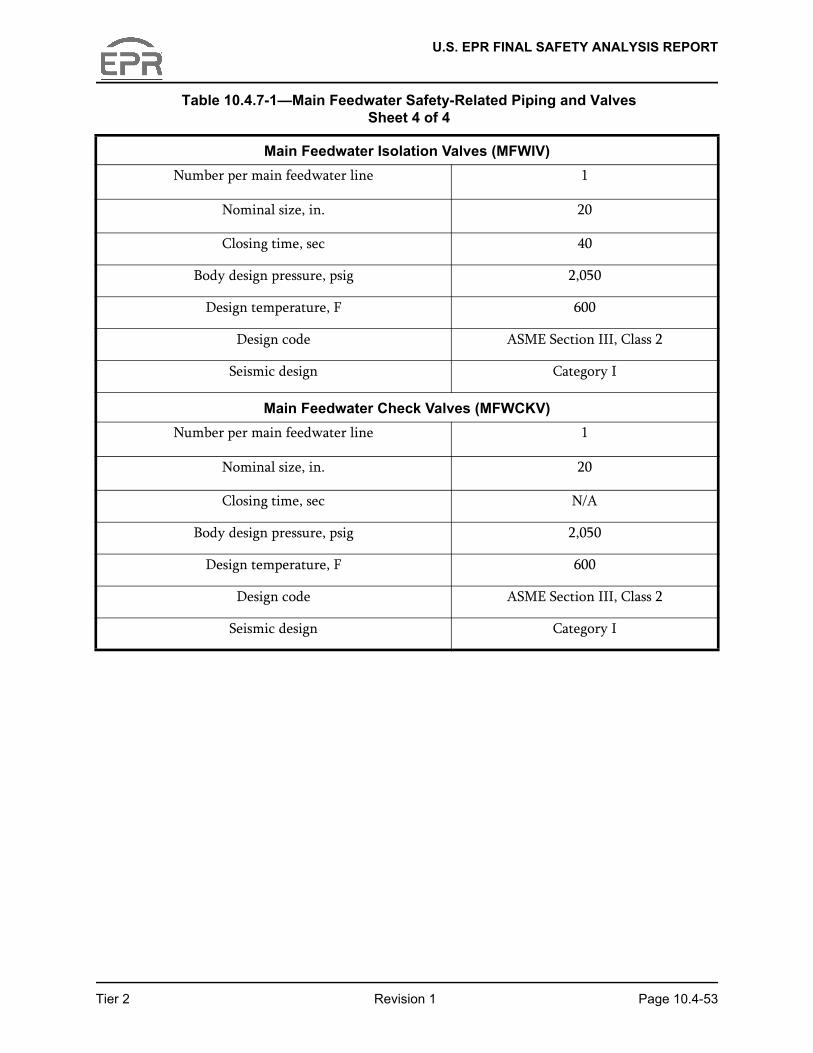
data for feedwater piping and valves is given in Table 10.4.7-1—Main Feedwater Safety-Related Piping and Valves.
Condensate and Feedwater Piping
Refer to Section 3.6 for a description of piping and support design.
Main Feedwater Full Load Isolation Valves
Each full load feedwater control valve features an upstream isolation valve that quickly and automatically closes when feedwater isolation is necessary. The main feedwater full load isolation valves (MFWFLIV) are gate valves with hydraulic-pneumatic actuators. The actuator hydraulic diagram is provided in Figure 10.4.7-2—Feedwater Full Load Isolation Valve Hydraulic Actuators.
The hydraulic-pneumatic actuator is a piston actuator with its upper chamber charged with high pressure nitrogen and its lower chamber connected to a hydraulic oil system. The nitrogen stored in the upper chamber serves as a spring to close the valve without failure. The hydraulic oil supplied to the lower chamber opens the valve.
The actuator upper chamber is closed and continuously maintained at high pressure. The upper chamber is manually connected to a nitrogen gas cylinder to restore nominal pressure as needed.
Each actuator has its own hydraulic oil system which pumps hydraulic oil from a tank into the actuator lower chamber.
Fast closure is performed by dumping the hydraulic oil back to the oil tank via two redundant lines. On each dump line there is a dump valve pilot operated by a solenoid valve which operates on the energize-to-trip principle. This arrangement prevents a failure of any pilot valve from causing failure to close (two redundant control lines) of the MFWFLIVs.
Main Feedwater Low Load Isolation Valves
A common valve quickly and automatically isolates both the low load and very low load feedwater control valves when feedwater isolation is necessary. The main feedwater low load isolation valve (MFWLLIV) is a motor-operated gate valve.
Feedwater Control Valves
● Very Low Load Valves—The main feedwater very low load control valves (MFWVLLCVs) are motor-operated globe type control valves that are designed to regulate flow from 0 to 5 percent load.
Tier 2 Revision 1 Page 10.4-37
U.S. EPR FINAL SAFETY ANALYSIS REPORT
● Low Load Valves—The main feedwater low load control valves (MFWLLCVs) are motor-operated globe type control valves that are designed to regulate flow from 5 to 20 percent load.
● Full Load Valves—The main feedwater full load control valves (MFWFLCVs) are motor-operated globe type control valves that are designed to regulate flow from 20 to 100 percent load.
Containment Isolation Valves
The CIVs in the CFS include a MFWIV, which is a motor-operated CIV just outside the RB. Additionally, a damped check valve inside the RB provides containment isolation. The check valve is dampened to reduce the potential for water hammer in a FWLB event.
The CIVs in the condensate system first stage blowdown cooler supply and return lines include a motor-operated isolation valve in the supply line located just outside the RB. Additionally, a check valve in the supply line inside the RB provides containment isolation. A motor-operated isolation valve in the return line located just outside the RB provides containment isolation. Additionally, a second motor-operated isolation valve in the return line located inside the RB provides containment isolation. A relief valve is provided downstream of the inside containment return line isolation valve to prevent overpressurization of the containment penetration due to thermal expansion of trapped fluid.
Main Feedwater Pumps
There are three 33 percent capacity horizontal MFW pumps driven by constant speed electric motors. Each pump consists of an integral, low speed, single stage booster pump and a high speed, multi-stage main pump. Both the booster pump and main pump are driven by the same motor, with gearing providing the speed differences.
Startup and Shutdown Feedwater Pump
There is one five percent capacity startup and shutdown feedwater pump. It is a horizontal multi-stage pump driven by a constant speed electric motor.
Condensate Pumps
There are three 50 percent capacity condensate pumps. Each pump is a vertical, canned type pump designed for low net positive suction head (NPSH) conditions and driven by a constant speed electric motor.
Feedwater Heater Drain and MSR Drain Pumps
The drain pumps are horizontal pumps driven by a constant speed electric motor.
Tier 2 Revision 1 Page 10.4-38
U.S. EPR FINAL SAFETY ANALYSIS REPORT
Low Pressure Feedwater Heaters
The LP FWHs are horizontal shell and tube design constructed of carbon steel with stainless steel tubes.
High Pressure Feedwater Heaters
The HP FWHs are horizontal shell and tube design constructed of carbon steel with stainless steel tubes.
Deaerator–Feedwater Storage Tank
The deaerator–feedwater storage tank is a direct contact heat exchanger with an integral spray-type deaerator. The feedwater storage tank acts as a buffer for feedwater supply to the SGs.
10.4.7.2.3 System Operation
Prestartup
The EFW pumps are normally used for SG filling coincident with their surveillance testing. However, if so desired the startup and shutdown feedwater pump can be used to fill the SGs. The recirculation valve automatically modulates to maintain pump minimum flow and the main feedwater very low load control valves (MFWVLLCV) are used to fill the SGs.
The feedwater lines are warmed by aligning valves so that flow is from the deaerator–feedwater storage tank, through the startup and shutdown feedwater pump, to the feedwater valve stations and back through the HP feedwater heaters to the deaerator–feedwater storage tank. During the warming process, the recirculation valve maintains minimum flow through the startup and shutdown feedwater pump.
Plant Startup
The condensate system is started before the SG blowdown, feedwater or startup and shutdown feedwater systems. The condenser need not be evacuated. However, the condenser circulating water pumps, part of the circulating water system (CWS), are operating to remove heat loads from the condenser.
Using one condensate pump during recirculation, the system is vented and pressurized in stages. Turbine sealing may begin once condensate flow is established through the gland steam condenser. Similarly, SG blowdown begins once condensate flow is established through the blowdown cooler. Once water is admitted to the deaerator–feedwater storage tank, the low range makeup valve automatically maintains deaerator–feedwater storage tank level.
Tier 2 Revision 1 Page 10.4-39
U.S. EPR FINAL SAFETY ANALYSIS REPORT
At approximately 50 percent load, a second condensate pump is started to maintain flow. The condensate pump recirculation valve gradually modulates closed as the unit load is increased.
Using the startup and shutdown feedwater pump, its recirculation valve automatically modulates to maintain pump minimum flow and the main feedwater very low load control valves (MFWVLLCV) automatically modulate to maintain SG water level. At approximately five percent load, one of the MFW pumps is started, as required to maintain SG water level. Subsequently, the second and third MFW pumps are started. The feedwater pumps are started in a staged manner to reduce the possibility of overfeed in the event of controls malfunctioning.
As load is increased, flow control is automatically transferred from the MFWVLLCVs, to the MFWLLCVs and eventually to the MFWFLCVs.
Normal Operation
During normal plant operation, two condensate pumps are in service with flow from the hotwell, through the gland steam condenser LP FWHs, and blowdown cooler into the deaerator–feedwater storage tank. Normally, there is no flow to the turbine bypass or exhaust hood sprays. The standby condensate pump is normally set to automatically start on failure of an operating pump.
During normal operation, three MFW pumps are in service with flow from the deaerator–feedwater storage tank, through the HP FWHs and second stage reheater drain coolers, and into the SG. The standby and shutdown feedwater pump is normally set to start on failure of all main pumps.
Shutdown
As unit load is decreased, the condensate pump recirculation valve gradually modulates open. At approximately 50 percent load, one condensate pump is shut down. A single condensate pump is kept in service so long as there is a demand for spray water, gland steam cooling or blowdown cooling.
As unit load is decreased, the MFW pump recirculation valves gradually modulate open. Flow control automatically transfers from the MFWFLCVs, to the MFWLLCVs and then to the MFWVLLCVs. At approximately 65 percent load, one MFW pump is shut down. Subsequently, the second and third MFW pumps are shut down. The startup and shutdown feedwater pump is started before stopping the last main pump and remains in service until cooling is provided by the residual heat removal system (RHRS). As in startup, the feedwater pumps are shut down in a staged manner to reduce the possibility of overfeed in the event of controls malfunctioning.
Tier 2 Revision 1 Page 10.4-40
U.S. EPR FINAL SAFETY ANALYSIS REPORT
Abnormal Operation
Single Main Feedwater Pump Failure
Upon failure of a single main feedwater pump, the resulting mismatch between reactor power and feedwater flow will automatically cause a partial reactor trip to 50 percent power level.
Multiple Feedwater Pump Failure / Loss of Normal Feedwater
Upon a failure of multiple feedwater pumps, the resulting mismatch between reactor power and feedwater flow will automatically cause a partial reactor trip to 50% power level. If the feedwater flow is below 50 percent, a full reactor trip is automatically initiated which results in the closure of all full load feedwater control and isolation valves. If steam generator water level drops below a predetermined setpoint, the Emergency Feedwater System will automatically start to maintain SG inventory.
Loss of Offsite Power (LOOP)
A loss of off site power results in the loss of all main feedwater pumps and the startup and shutdown feedwater pump. The response is the same as for a multiple feedwater pump failure or loss of normal feedwater.
Loss of Emergency Power
The MFWIV containment isolation, very low load control, low load control, and full load control valves are powered by their own divisions while the low load and full load isolation valves are powered by a neighboring division. Therefore, the loss of one division of electrical power does not result in a loss of the feedwater or containment isolation function.
Excessive Feedwater Flow
Excessive feedwater flow could be caused by a control malfunction. If SG level increases to a predetermined setpoint, a reactor trip will automatically occur on high steam generator level. The reactor trip initiates a turbine trip and closure of all full load feedwater control and isolation valves. The resulting shrink in SG level may cause the steam generator water level to fall below the SG high level reactor trip setpoint. However if steam generator level remains high, feedwater flow to the affected steam generator is terminated by automatic closure of the associated low load and very low load control valves, low load isolation valve, and main feedwater isolation valve.
Refer to Chapter 15 for a description of anticipated operational occurrences.
Tier 2 Revision 1 Page 10.4-41
U.S. EPR FINAL SAFETY ANALYSIS REPORT
Accident Conditions
Small Feedwater Line Breaks
Small feedwater line breaks are those within the feedwater pumping capability to compensate for the loss. The operator will be alerted to a small break by a high feedwater flow rate relative to reactor power and a decreasing deaerator / feedwater storage tank level. Dependent on break location, the unit may have to be shut down for repair. Safety-related feedwater system components are qualified for environmental conditions resulting from feed line breaks and their functions are not compromised.
Large Main Feedwater Line Break inside Containment between Check Valve and Steam Generator
A large main feedwater line break between the check valve and steam generator will result in loss of both pressure and inventory of the affected steam generator. The inventory of the unaffected steam generators will also decrease due to the loss of feedwater out the break but to a lesser extent. The reduced steam generator water inventory will reduce secondary side heat removal and cause an increase in reactor coolant temperature. A reactor trip will result from one or more of the following signals:
● High pressurizer pressure.
● Low steam generator level.
● High steam generator pressure drop.
● Low steam generator pressure.
The reactor trip will cause closure of all full load feedwater control and isolation valves which will reduce the feedwater loss. However, the affected steam generator will continue to depressurize and inventory in all steam generators will continue to drop. Feedwater flow to the affected steam generator will be automatically terminated on either of the following signals:
● High – High steam generator pressure drop.
● Low – Low steam generator pressure.
Feedwater flow to the affected steam generator is terminated by the automatic closure of the associated low load and very low load control valves, low load isolation valve, and main feedwater isolation valve. The low load flow paths for the unaffected steam generators remain open. If a steam generator’s water level should continue to drop, its emergency feedwater pump will automatically start to maintain inventory.
Tier 2 Revision 1 Page 10.4-42
U.S. EPR FINAL SAFETY ANALYSIS REPORT
Large Main Feedwater Line Break Upstream Of Check Valve
Safety-related feedwater system components are designed to withstand the effects of a main feedwater line break without loss of function. A feed line break upstream of the check valve will cause the check valve to close and prevent depressurization of the affected steam generator. The feedwater flow to all steam generators will be reduced due to feed flow losses out the break. The resulting reduced steam generator water inventory will reduce secondary side heat removal and cause an increase in reactor coolant temperature. A reactor trip will result from one or more of the following signals:
● High pressurizer pressure.
● Low steam generator level.
● High steam generator pressure drop.
● Low steam generator pressure.
The reactor trip will cause closure of all full load feedwater control and isolation valves. However, the inventory in all steam generators will continue to drop until the emergency feedwater pumps automatically start to maintain level.
Main Steam Line Break (MSLB)
A main steam line break will cause all steam generators to begin depressurizing. Dependent on break location, a reactor trip will result from high containment pressure or one or both of the following which also causes main steam isolation:
● High steam generator pressure drop.
● Low steam generator pressure.
The reactor trip will cause closure of all full load feedwater control and isolation valves. If the break is downstream of the main steam isolation valves (MSIV), the depressurization will be stopped. If the break is upstream of a MSIV, the affected steam generator will continue to depressurize.
In order to prevent over filling a steam generator, feedwater flow is terminated by automatic closure of the low load and very low load control valves, the low load isolation valve, and main feedwater isolation valve on any of the following conditions:
● High – High steam generator pressure drop.
● Low – Low steam generator pressure.
● High steam generator level with time delay after reactor trip.
Tier 2 Revision 1 Page 10.4-43
U.S. EPR FINAL SAFETY ANALYSIS REPORT
10.4.7.2.4 Steam Generator Tube Rupture (SGTR)
To prevent the release of contaminated fluid from the affected SG, the SG is isolated if a Partial Cooldown signal is present and:
● High Steam Generator Water Level
Or
● High Main Steam Activity
This will cause the main feedwater isolation valve, the full load isolation valve, the full load control valve, the low load isolation valve, the low load control valve and the very low load control valve for the affected SG to close. The SGTR mitigation functions will have manual initiation capability so they may be initiated by manual operator actions to mitigate the SGTR event.
ATWS – Loss of Offsite Power
Loss of offsite power will cause loss of the normal feedwater. The emergency feedwater pumps will start on low steam generator level to maintain inventory. Secondary heat removal will be by the main steam relief trains and the main steam safety valves.
ATWS – Loss of Normal Feedwater
The secondary side response is the same as for ATWS – Loss of Offsite Power.
Refer to Chapter 15 for a description of accident analyses.
10.4.7.3 Safety Evaluation
The design of the safety-related portions of the CFS satisfies GDC 2 regarding the effects of natural phenomena.
● Safety-related portions of the CFS are located inside containment and valve rooms, which are part of the SBs. Safeguard Buildings 1 and 4 each contain two valve rooms. These buildings are designed to withstand the effects of natural phenomena, such as earthquakes, tornadoes, hurricanes, floods, tsunami and seiches. Section 3.3, Section 3.4, Section 3.5, Section 3.7 and Section 3.8 provide the bases for the adequacy of the structural design of these buildings.
● Safety-related portions of the CFS are designed to remain functional during and after a safe shutdown earthquake (SSE). Section 3.7 provides the design loading conditions that are considered.
● Consistent with the guidance in RG 1.29, the condensate system piping penetrating the containment and the associated CIVs are designed to Seismic
Tier 2 Revision 1 Page 10.4-44
U.S. EPR FINAL SAFETY ANALYSIS REPORT
Category I requirements. The condensate system piping inside containment or valve rooms that is not Seismic Category I, is designed to Seismic Category II requirements. Also consistent with the guidance in RG 1.29, feedwater system piping that is part of the primary and secondary reactor containment, is designed to Seismic Category I requirements; these design requirements extend to the first seismic restraint beyond the defined boundary.
● Portions of the condensate system penetrating the containment and the associated CIVs are designated Quality Group B and designed as ASME Boiler and Pressure Vessel Code, Section III, Class 2 (Reference 2) components. The cooling water supply and return piping inside containment is designated Quality Group D and Seismic Category II.
● Feedwater system CIVs and adjacent piping up to the SGs are designated Quality Group B and designed as Reference 3, Class 2 components subject to the requirements of Subsection NC. Feedwater system piping upstream of the CIVs up to the fixed restraint, is designated Quality Group C and designed as ASME Boiler and Pressure Vessel Code, Section III, Class 3 (Reference 4) components subject to the requirements of Subsection ND.
● Inside the four valve rooms, the feedwater piping is routed in four individual and separate trains so that internal flooding does not prevent the main feedwater system (MFWS) from performing its safety-related functions. Refer to Section 3.4.3.4 for a discussion of flooding in the valve compartments. Critical components in the MFWS are located inside the feedwater valve rooms.
● The CIV in the condensate system are described in Section 10.4.7.2.2. The outside CIV are located in the valve room for the steam generator blowdown system (SGBS). Flooding protection for these valves is described in Section 3.4.3.4.
The design of the safety-related portions of the CFS satisfies GDC 4 regarding being able to accommodate the effects of and to be compatible with the environmental conditions associated with normal operation, maintenance, testing and postulated accidents, including loss-of-coolant accidents; also, these portions are protected from the dynamic effects associated with possible fluid flow instabilities (e.g., water hammer) during normal plant operation as well as during upset or accident conditions.
● The CFS design is consistent with the guidance contained in BTP 10-2 (Reference 5) for reducing the potential for water hammers in SGs and the guidance related to feedwater-control-induced water hammer provided in NUREG-0927 (Reference 6). The SGs have features that minimize the potential for water hammer. Refer to Section 5.4.2.2 for a description of these features. The design and operating features that reduce the potential for water hammer in the condensate and feedwater systems are:
− Tilting disc check valve on the discharge of each condensate pump prevents back flow in the upstream system. The tilting disc type has a lower pressure pulse upon closing than some other valve types.
Tier 2 Revision 1 Page 10.4-45
U.S. EPR FINAL SAFETY ANALYSIS REPORT
− The feedwater system has a smaller startup and shutdown feedwater pump that reduces the potential for water hammer.
− Piston assisted check valve on the discharge of each feedwater pump prevents reverse flow with a low pressure pulse upon closing.
− Damped check valve upstream of each steam generator feedwater nozzle prevents reverse flow with low pressure pulse upon closing.
− Main feedwater flow to each steam generator is controlled through three flow paths with different flow capacities. The three flow paths are staggered in startup and shutdown. The motor operated feedwater control valves do not open or close rapidly and they fail as is. Each control valve is individually modulated by a dedicated proportional integral derivative (PID) step controller. As described in Section 7.7.2.3, the very low load control valve has a minimum valve position to provide a minimum flow rate to produce the potential for thermal stratification and water hammer phenomena.
− In the condensate supply line to the steam generator blowdown cooler, valve opening and closing times are chosen to reduce water hammer effects.
● Safety-related portions of the CFS are protected from the effects of pipe breaks and leaks. Inside the SB, but outside the valve compartments, restraints are provided to prevent the failure of another system from affecting the CFS. Similarly, pipe restraints are provided to prevent failure of one feedwater line from affecting the other feedwater lines. Information on high-energy pipe break locations and evaluation of effects is provided in Section 3.6.1 and Section 3.6.2.
● In the event of a FWLB inside containment or a MSLB, the CFS is designed to limit high energy fluid to the broken loop. For a FWLB upstream of the MFIV (outside of containment), the CFS is designed to prevent the blowdown of any SG. The evaluation for these events is provided in Chapter 15.
● The safety-related portions of the CFS is protected from the effects of external missile hazards by building structures. The non-safety related portions of feedwater piping located outside the structures may be impacted from external missiles. In the event of a failure of these externally routed lines, the SG pressure boundary is maintained by the CFS containment check valves. If available, normal feedwater to the other two SGs are used for heat removal. Otherwise, EFW is used for heat removal.
● Portions of the CFS located inside the containment are maintained at acceptable ambient conditions by the containment ventilation system. The valves stations are maintained at acceptable ambient conditions by the main steam and feedwater valve compartment ventilation system. In the event of a loss of offsite power or station blackout event, heat loss from the feedwater piping maintains acceptable conditions in the valve compartments.
● The CFS design considers the loads associated with startup, shutdown, hot alkaline wash, pump shutoff head and hydrostatic testing. The safety-related portions of
Tier 2 Revision 1 Page 10.4-46
U.S. EPR FINAL SAFETY ANALYSIS REPORT
the CFS are qualified to function in normal, test and accident environmental conditions. The environmental qualification program is discussed in Section 3.11.
The design of the safety-related portions of the CFS satisfies GDC 5 regarding sharing of systems. Safety-related portions of the CFS are not shared among nuclear power units.
The design of the safety-related portions of the CFS satisfies GDC 44 regarding the capability to transfer heat from structures, systems and components important to safety to an ultimate heat sink.
● The emergency feedwater system (EFWS) is designed as a separate system from the CFS and has its own water supply. The CFS does not provide a flow path for emergency feedwater (EFW). The CFS does not perform safety-related functions with respect to transferring heat from structures, systems and components important to safety to the ultimate heat sink.
The design of the safety-related portions of the CFS satisfies GDC 45 regarding the performance of periodic inservice inspection of important components and equipment.
● The CFS is designed to permit periodic inspection of safety-related components. Inservice inspection of CFS components is performed in accordance with the ASME Boiler and Pressure Code, Section XI (Reference 7). Refer to Section 6.6 for a description of the inservice inspection program for the CFS valves.
● Refer to Section 10.3.6.3 for a description of flow accelerated corrosion.
The design of the safety-related portions of the CFS satisfies GDC 46 regarding the performance of functional testing of the system and components to demonstrate structural integrity and leak-tightness, operability and performance of active components.
● The CFS is designed to permit periodic testing during plant operation to confirm the structural and leak tight integrity of its components, as well as the operability and performance of the active components of the system. Refer to Section 3.9.6 for a description of the inservice testing program for CFS valves.
The design of the safety-related portions of the CFS satisfies single failure criterion. The means of feedwater and containment isolation are redundant and diverse. A single failure will not result in the loss of feedwater or containment isolation function.
● Inside the four valve rooms, the feedwater piping is routed in four individual and separated trains (called divisions) so that failure of another system cannot affect the CFS, nor can failure of one feedwater line affect the other feedwater lines. Inside the RB, the feedwater lines are routed separately in the SG bunkers with no others lines, so that failure of another system cannot affect the CFS nor can failure of one feedwater line affect the other feedwater lines. Inside the SB, but outside the valve rooms, there are no components capable of producing internal missiles
Tier 2 Revision 1 Page 10.4-47
U.S. EPR FINAL SAFETY ANALYSIS REPORT
which could affect the CFS. Inside the valve rooms, the feedwater piping is routed in four individual and separated trains so that there is no source of internal missiles. Inside the containment, the feedwater lines are protected from the effects of reactor coolant pump flywheel failure by being routed within the SG bunkers.
● Redundancy in feedwater isolation is provided by the full load isolation valve and the low load isolation valve in series with the main feedwater isolation valve (FWIV). Backup isolation is provided by the, full load feedwater control valve, low load control valve, and very low load control valve. Redundancy in feedwater containment isolation is provided by the main feed water isolation valve and its downstream check valve. The MFWIVs and their downstream check valves provide diverse means of containment isolation. Redundant valves are provided in the SG blowdown cooler supply and return lines so that containment isolation is provided even with a single valve failure to close.
● One pilot solenoid on full load feedwater isolation valve is powered from its associated division. The second pilot solenoid on the divisions 1–4 full load MFWIVs are powered from divisions 3, 4, 1, and 2, respectively. The division 1–4 low load MFWIVs are powered from divisions 3, 4, 1, and 2, respectively.
● Each feedwater control valve is powered from its associated division safety-related uninterruptible power supply (UPS). Each MFWIV is powered from its associated division safety-related power source.
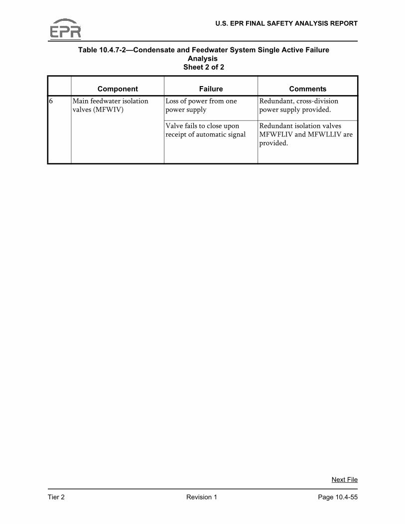
● Table 10.4.7-2 provides the results of a single active failure review of the CFS. These results demonstrate that a single active failure does not compromise the performance of system safety functions.
10.4.7.4 Inspection and Testing Requirements
Components in the CFS are inspected and tested during plant startup. Refer to Section 14.2 (test abstracts #059, #066, #149, #166, #185, #195, #196, #200, #201, #204, #214, #217 and #220) for initial plant startup and test program.
Inservice inspection and testing of CFS components is performed in accordance with Reference 7. A description of the inservice testing and the inservice inspection program for the feedwater isolation valves, feedwater control valves and CIVs is contained in Section 3.9.6 and Section 6.6, respectively.
Instrumentation and controls (I&C) are calibrated during startup, and recalibrated as necessary to maintain system operability.
10.4.7.5 Instrumentation Requirements
All MFWFLIVs automatically close on a reactor trip. The MFWLLIV and MFWIVs associated with a particular SG automatically close on an MFW isolation signal. Refer
Tier 2 Revision 1 Page 10.4-48
U.S. EPR FINAL SAFETY ANALYSIS REPORT
to Section 7.7 for a description of feedwater flow instrumentation and controls (I&C) and SG level I&C.
Flow control of the main condensate for cooling the first stage steam generator blowdown cooler is described in Section 10.4.8.
An ultrasonic flow meter in the feedwater lines measures feedwater flow and temperature, and provides input to the core power calorimetric calculation. Refer to Section 7.7 for a description of flow meters used for feedwater flow control.
10.4.7.6 References
1. ASME B31.1, “Power Piping,” The American Society of Mechanical Engineers, 2004.
2. ASME Boiler and Pressure Vessel Code, Section III, “Rules for Construction of Nuclear Facility Components,” Class 2 Components, The American Society of Mechanical Engineers, 2004.
3. ASME Boiler and Pressure Vessel Code, Section III, Division 1, Subsection NC including Article NC-7000: “Overpressure Protection,” The American Society of Mechanical Engineers, 2004.
4. ASME Boiler and Pressure Vessel Code, Section III: “Rules for Construction of Nuclear Facility Components,” Division 1, Subsection ND: Class 3 Components, The American Society of Mechanical Engineers, 2004.
5. NUREG-0800, BTP 10-2, “Design Guidelines for Avoiding Water Hammers in Steam Generators,” Revision 4, U.S. Nuclear Regulatory Commission, March 2007,
6. NUREG-0927, “Evaluation of Water Hammer Occurrence in Nuclear Power Plants," Revision 1, U.S. Nuclear Regulatory Commission, March 1984.
7. ASME Boiler and Pressure Vessel Code, Section XI: “Rules for Inservice Inspection of Nuclear Power Plant Components,” The American Society of Mechanical Engineers, 2004.
Tier 2 Revision 1 Page 10.4-49
U.S. EPR FINAL SAFETY ANALYSIS REPORT
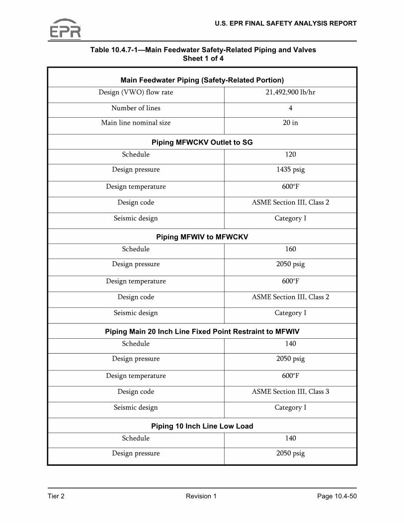
Table 10.4.7-1—Main Feedwater Safety-Related Piping and Valves Sheet 1 of 4
Main Feedwater Piping (Safety-Related Portion)Design (VWO) flow rate 21,492,900 lb/hr
Number of lines 4
Main line nominal size 20 in
Piping MFWCKV Outlet to SGSchedule 120
Design pressure 1435 psig
Design temperature 600°F
Design code ASME Section III, Class 2
Seismic design Category I
Piping MFWIV to MFWCKVSchedule 160
Design pressure 2050 psig
Design temperature 600°F
Design code ASME Section III, Class 2
Seismic design Category I
Piping Main 20 Inch Line Fixed Point Restraint to MFWIVSchedule 140
Design pressure 2050 psig
Design temperature 600°F
Design code ASME Section III, Class 3
Seismic design Category I
Piping 10 Inch Line Low LoadSchedule 140
Design pressure 2050 psig
Tier 2 Revision 1 Page 10.4-50
U.S. EPR FINAL SAFETY ANALYSIS REPORT
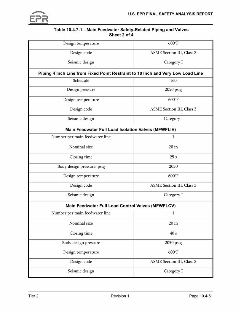
Design temperature 600°F
Design code ASME Section III, Class 3
Seismic design Category I
Piping 4 Inch Line from Fixed Point Restraint to 10 Inch and Very Low Load LineSchedule 160
Design pressure 2050 psig
Design temperature 600°F
Design code ASME Section III, Class 3
Seismic design Category I
Main Feedwater Full Load Isolation Valves (MFWFLIV)Number per main feedwater line 1
Nominal size 20 in
Closing time 25 s
Body design pressure, psig 2050
Design temperature 600°F
Design code ASME Section III, Class 3
Seismic design Category I
Main Feedwater Full Load Control Valves (MFWFLCV)Number per main feedwater line 1
Nominal size 20 in
Closing time 40 s
Body design pressure 2050 psig
Design temperature 600°F
Design code ASME Section III, Class 3
Seismic design Category I
Table 10.4.7-1—Main Feedwater Safety-Related Piping and Valves Sheet 2 of 4
Tier 2 Revision 1 Page 10.4-51
U.S. EPR FINAL SAFETY ANALYSIS REPORT
Main Feedwater Low Load Isolation Valves (MFWLLIV)Number per main feedwater line 1
Nominal size, in. 10
Closing time, sec 20
Body design pressure, psig 2,050
Design temperature, F 600
Design code ASME Section III, Class 3
Seismic design Category I
Main Feedwater Low Load Control Valves (MFWLLCV)Number per main feedwater line 1
Nominal size, in. 10
Closing time, sec 20
Body design pressure, psig 2,050
Design temperature, F 600
Design code ASME Section III, Class 3
Seismic design Category I
Main Feedwater Very Low Load Control Valves (MFWVLLCV)Number per main feedwater line 1
Nominal size, in. 4
Closing time, sec 20
Body design pressure, psig 2,050
Design temperature, F 600
Design code ASME Section III, Class 3
Seismic design Category I
Table 10.4.7-1—Main Feedwater Safety-Related Piping and Valves Sheet 3 of 4
Tier 2 Revision 1 Page 10.4-52
U.S. EPR FINAL SAFETY ANALYSIS REPORT
Main Feedwater Isolation Valves (MFWIV)Number per main feedwater line 1
Nominal size, in. 20
Closing time, sec 40
Body design pressure, psig 2,050
Design temperature, F 600
Design code ASME Section III, Class 2
Seismic design Category I
Main Feedwater Check Valves (MFWCKV)Number per main feedwater line 1
Nominal size, in. 20
Closing time, sec N/A
Body design pressure, psig 2,050
Design temperature, F 600
Design code ASME Section III, Class 2
Seismic design Category I
Table 10.4.7-1—Main Feedwater Safety-Related Piping and Valves Sheet 4 of 4
Tier 2 Revision 1 Page 10.4-53
U.S. EPR FINAL SAFETY ANALYSIS REPORT
Table 10.4.7-2—Condensate and Feedwater System Single Active Failure Analysis
Sheet 1 of 2
Component Failure Comments 1 Main feedwater full load
isolation valves (MFWFLIV)Loss of power from one power supply
Loss of one power supply has no effect on ability of valve to close. Valve actuator has 2 redundant closure systems. Valve closure is controlled by 2 cross-division power supplies provided to the actuator closing systems.
Valve fails to close upon receipt of automatic signal
Redundant isolation valves MFWFLCV and MFWIV provided in each main feedwater line.
2 Main feedwater low load isolation valves (MFWLLIV)
Loss of power from one power supply
Redundant, cross-division power supply provided.
Valve fails to close upon receipt of automatic signal
Redundant isolation valve MFWLLCV and MFWIV provided.
3 Main feedwater full load control valves (MFWFLCV)
Loss of power from one power supply
Redundant, cross-division power supply provided.
Valve fails to close upon receipt of automatic signal
Redundant isolation valves MFWFLIV and MFWIV provided in each main feedwater line.
4 Main feedwater low load control valves (MFWLLCV)
Loss of power from one power supply
Redundant, cross-division power supply provided.
Valve fails to close upon receipt of automatic signal
Redundant isolation valves MFWLLIV and MFWIV are provided.
5 Main feedwater very low load control valves (MFWVLLCV)
Loss of power from one power supply
Redundant, cross-division power supply provided.
Valve fails to close upon receipt of automatic signal
Redundant isolation valves MFWFLIV and MFWLLIV are provided.
Tier 2 Revision 1 Page 10.4-54
U.S. EPR FINAL SAFETY ANALYSIS REPORT
6 Main feedwater isolation valves (MFWIV)
Loss of power from one power supply
Redundant, cross-division power supply provided.
Valve fails to close upon receipt of automatic signal
Redundant isolation valves MFWFLIV and MFWLLIV are provided.
Table 10.4.7-2—Condensate and Feedwater System Single Active Failure Analysis