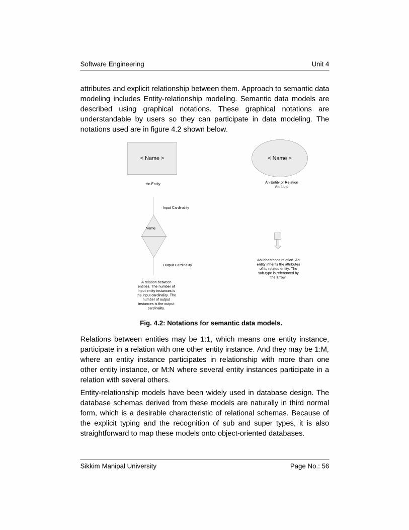
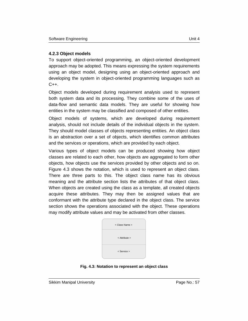
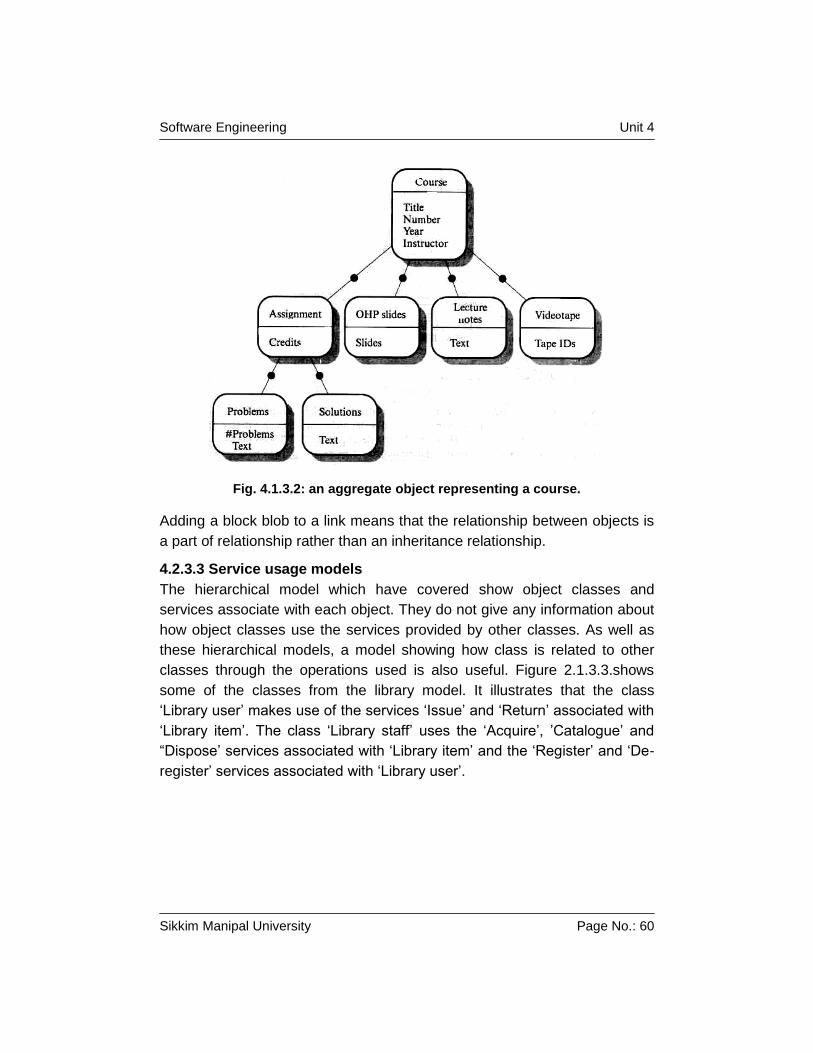
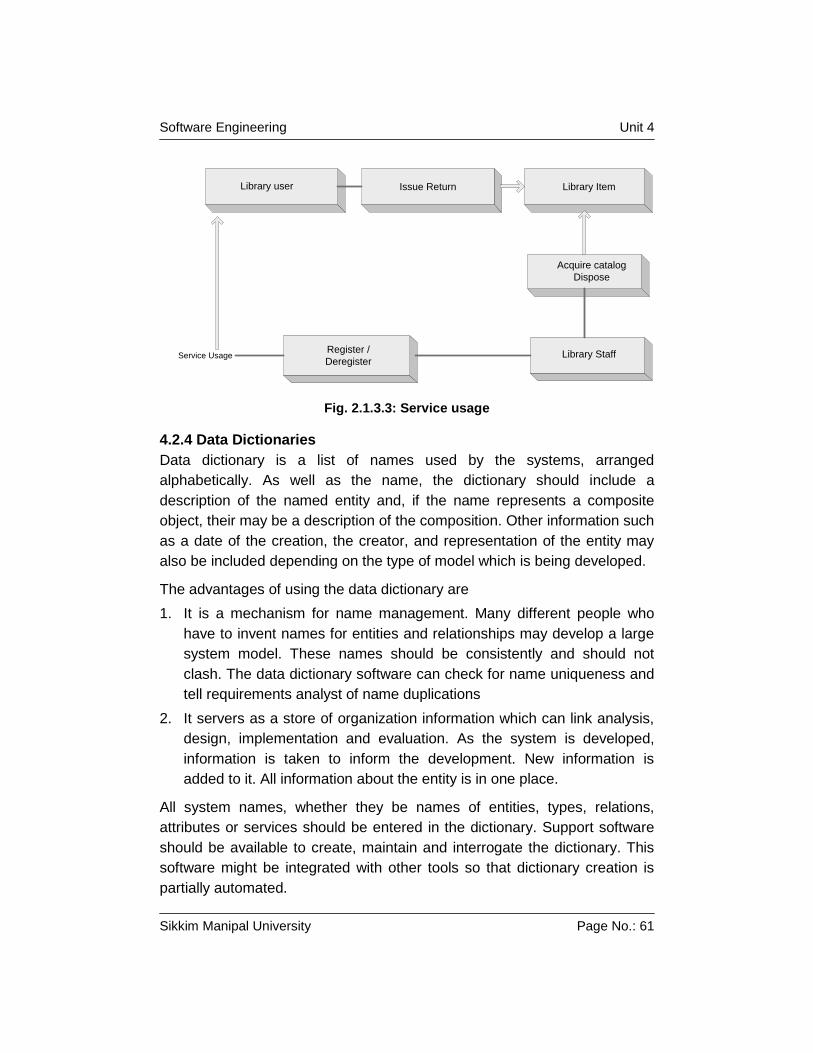
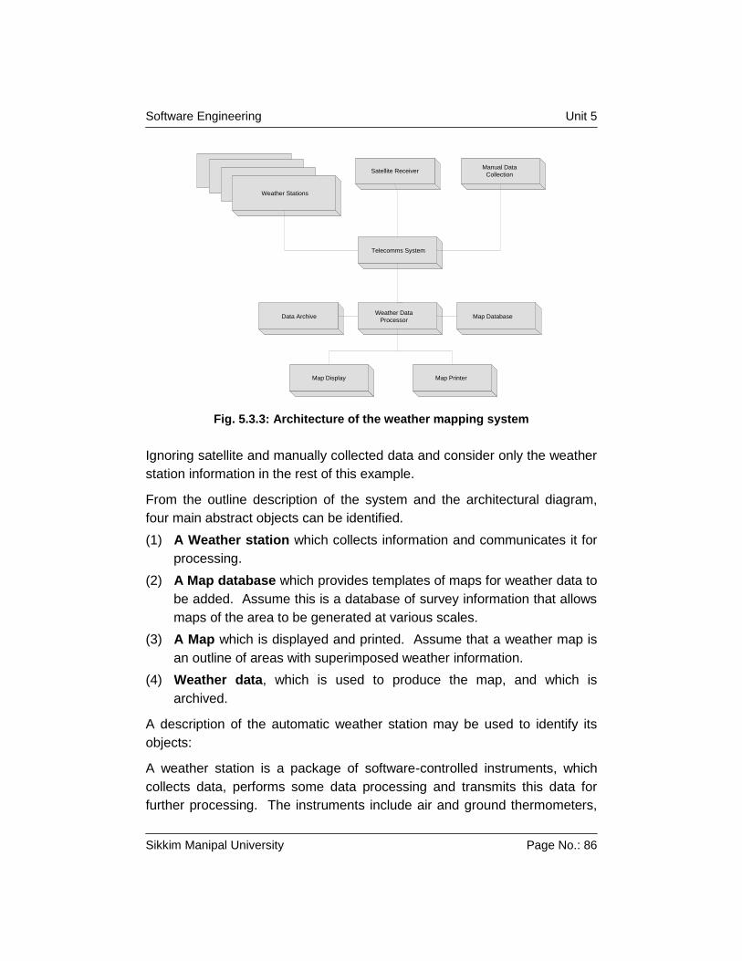
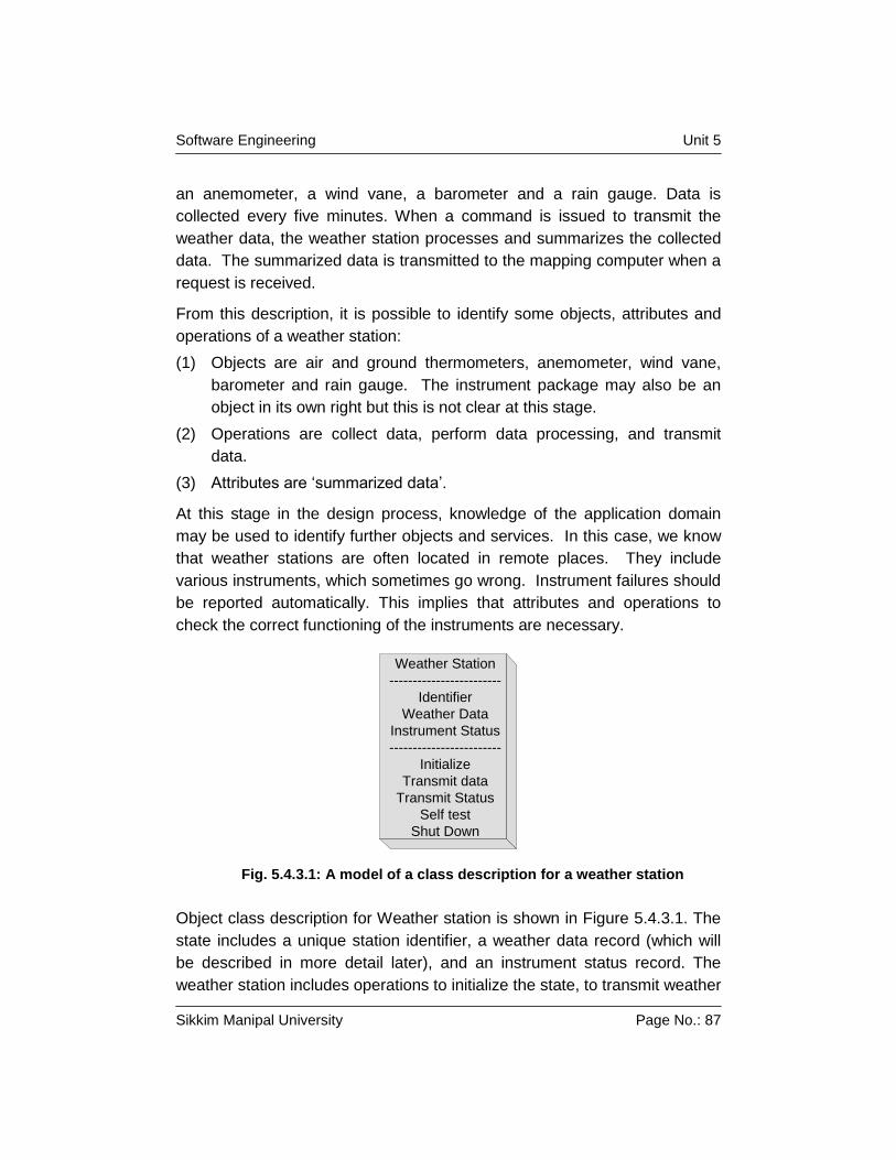
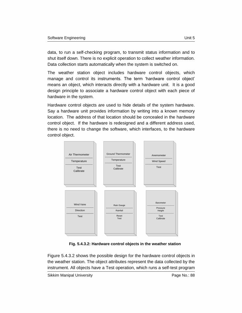
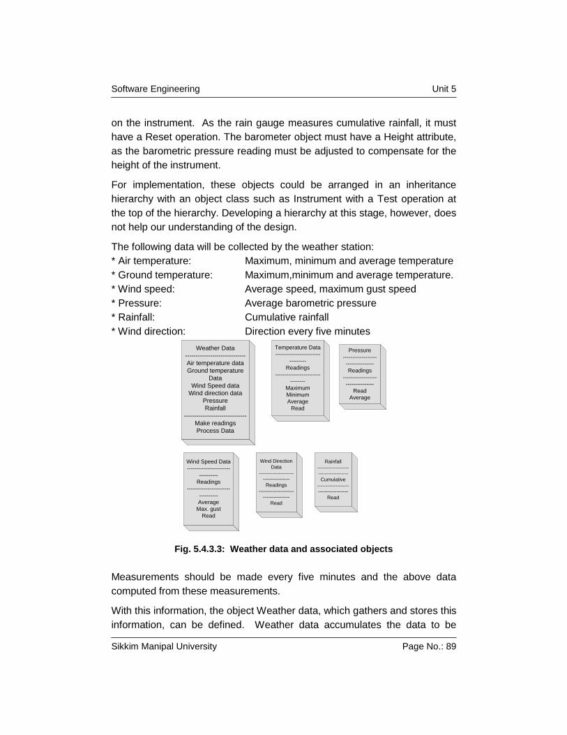
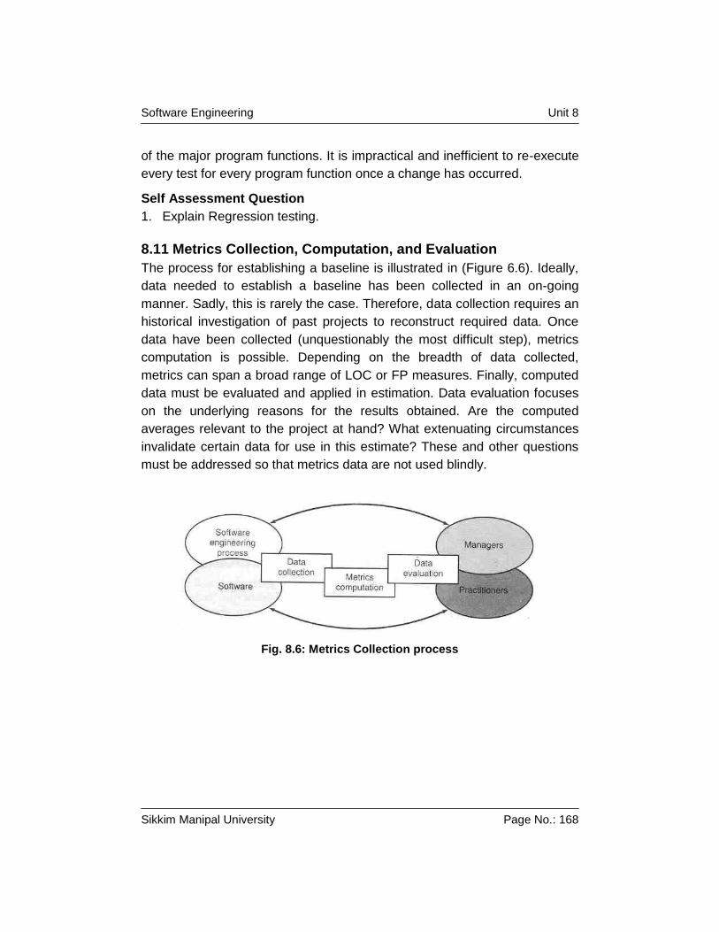
Software Engineering Unit 1 Sikkim Manipal University Page No.: 1 Unit 1 Software Development Approaches Structure 1.1 Introduction Objective 1.2 Evolving Role of Software 1.3 Software Characteristics 1.4 Software Applications 1.5 Summary 1.6 Terminal Questions 1.7 Answers to Terminal Questions 1.1 Introduction Computer software has become a driving force. It is the engine that drives business decision making. It serves as the basis for modern scientific investigation and engineering problem solving. It is a key factor that differentiates modern products and services. It is embedded in systems of all kinds: transportation, medical, telecommunications, military, industrial processes, entertainment, office products etc. Software is virtually inescapable in the modern world. And as we move into the twenty-first century, it will become the driver for new advances in everything from elementary education to genetic engineering. Computer software is the product that software engineers design and build. It encompasses programs that execute within a computer of any size and architecture, documents that encompass hard-copy and virtual forms and data that combine numbers and text but also includes representations of pictorial, video and audio information. Software is a set of application programs that are built by software engineers and are used by virtually everyone in the industrialized world either directly or indirectly. Software is important because it affects nearly every aspect of our lives and has become pervasive in our commerce, our culture and our everyday activities. Software is generally built like you build any other successful product, by applying a process that leads to a high quality result that meets the needs of
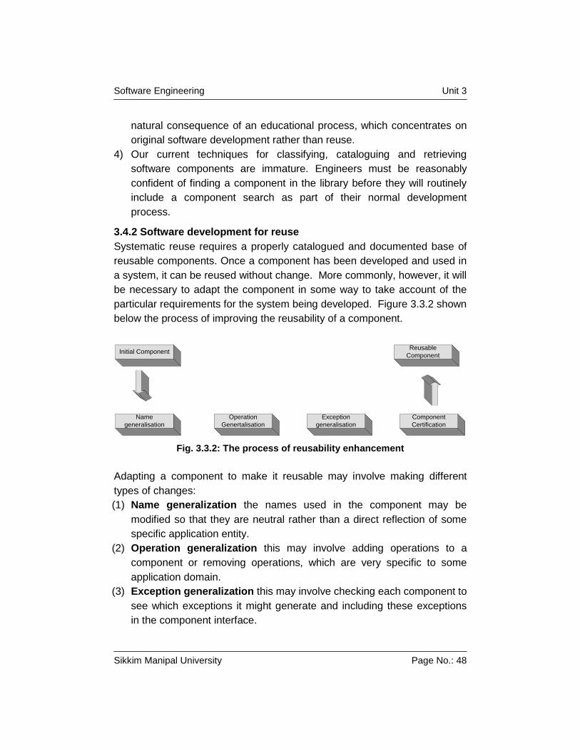
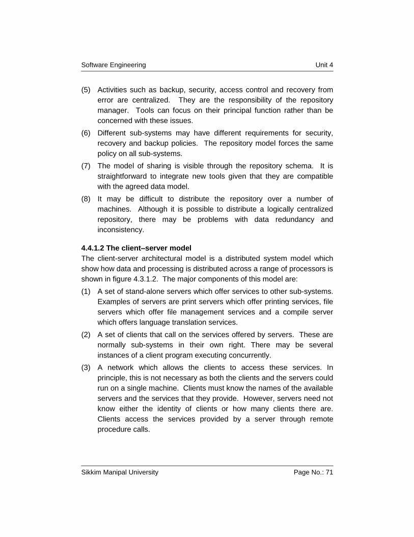
Transcript
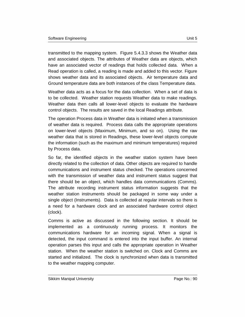
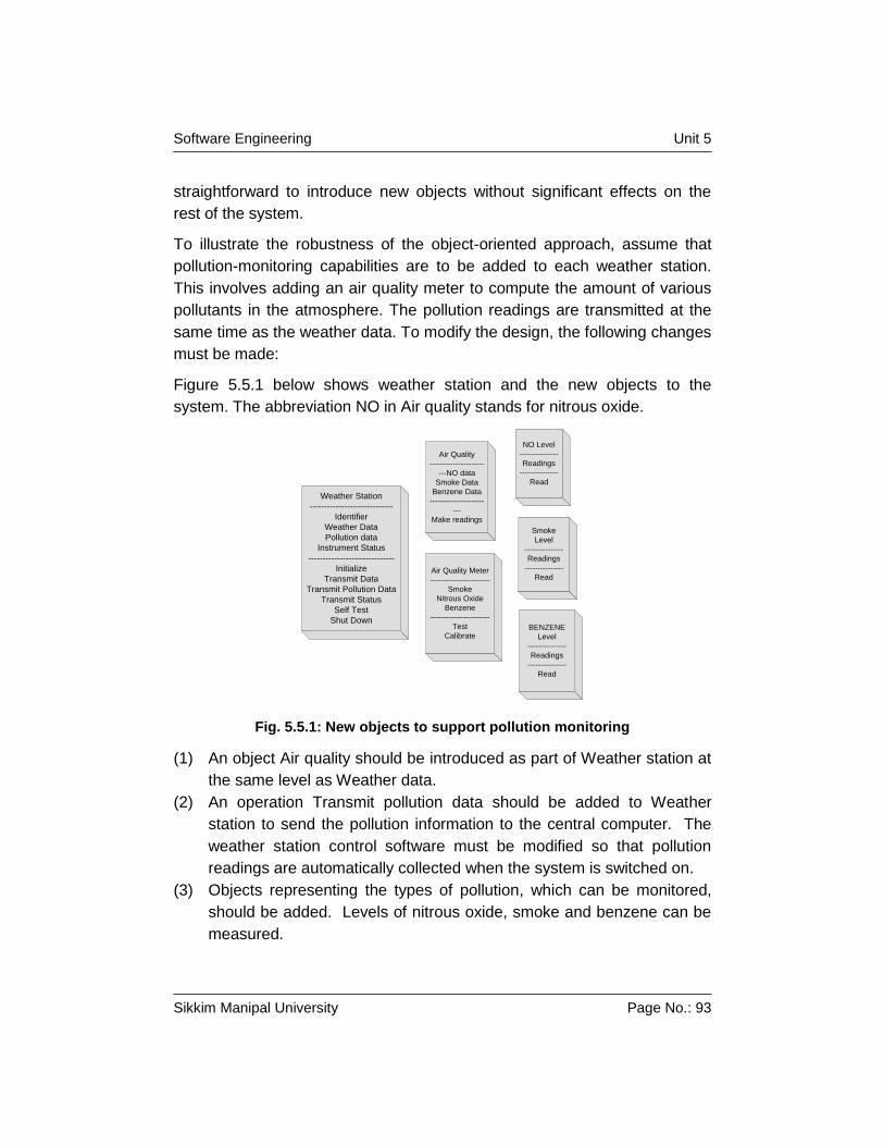
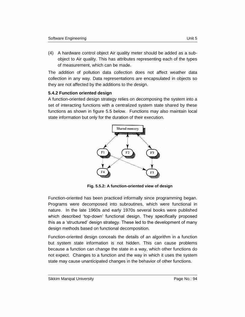
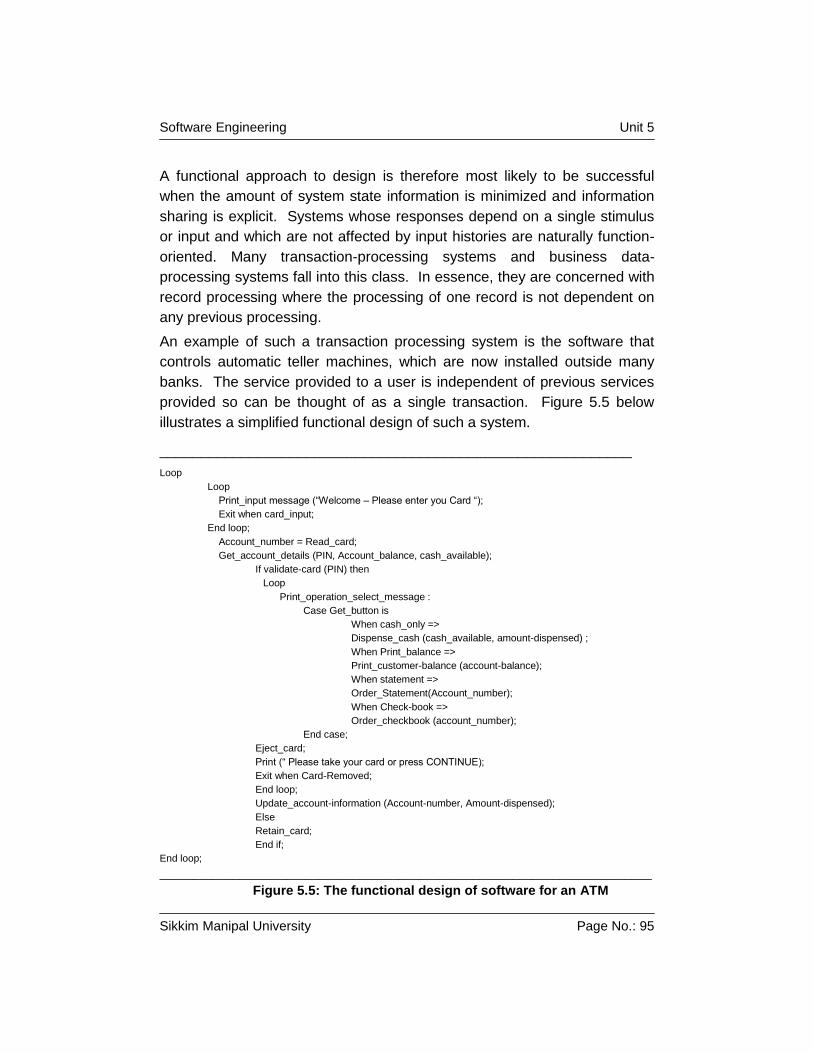
Software Engineering Unit 1
Sikkim Manipal University Page No.: 1
Unit 1 Software Development Approaches
Structure
1.1 Introduction
Objective
1.2 Evolving Role of Software
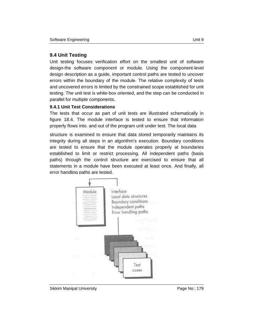
1.3 Software Characteristics
1.4 Software Applications
1.5 Summary
1.6 Terminal Questions
1.7 Answers to Terminal Questions
1.1 Introduction
Computer software has become a driving force. It is the engine that drives
business decision making. It serves as the basis for modern scientific
investigation and engineering problem solving. It is a key factor that
differentiates modern products and services. It is embedded in systems of
all kinds: transportation, medical, telecommunications, military, industrial
processes, entertainment, office products etc. Software is virtually
inescapable in the modern world. And as we move into the twenty-first
century, it will become the driver for new advances in everything from
elementary education to genetic engineering.
Computer software is the product that software engineers design and build.
It encompasses programs that execute within a computer of any size and
architecture, documents that encompass hard-copy and virtual forms and
data that combine numbers and text but also includes representations of
pictorial, video and audio information.
Software is a set of application programs that are built by software
engineers and are used by virtually everyone in the industrialized world
either directly or indirectly.
Software is important because it affects nearly every aspect of our lives and
has become pervasive in our commerce, our culture and our everyday
activities.
Software is generally built like you build any other successful product, by
applying a process that leads to a high quality result that meets the needs of
Software Engineering Unit 1
Sikkim Manipal University Page No.: 2
the people who will use the product. We apply a software engineering
approach to develop this product.
From the point of view of a software engineer, the work product is the
programs, documents and data that are computer software. But from the
user’s point of view, the work product is the resultant information that
somehow makes the user’s world better.
Objective
Upon completion of this Unit, you should be able to :
Understand the evolving role of software
The evolving role of software,
Software characteristics and
Software applications
1.2 Evolving role of software
Software impact on our society and culture continues to be profound. As its
importance grows, the software community continually attempts to develop
technologies that will make it easier, faster, and less expensive to build
high-quality computer programs. Some of these technologies are targeted at
specific application domain and others focus on a technology domain and
still others are more broad based and focus on operating systems.
Today software takes on a dual role. It is a product and at the same time,
the vehicle for delivering a product. As a product, it delivers the computing
potential and as a vehicle used to deliver the product, software acts as the
basis for the control of the computer, the networks and the creation and
control of other programs.
Software delivers the most important product of our time – information.
Software transforms personal data so that the data can be made more
useful in a local context. It manages business information to enhance
competitiveness. It provides a gateway to worldwide information networks
and provides the means for acquiring information in all of its forms.
The role of computer software has undergone significant change over a time
span of little more than 50 years. Dramatic improvements in hardware
performance, profound changes in computing architecture, vast increase in
memory and storage capacity, and a wide variety of input and output options
Software Engineering Unit 1
Sikkim Manipal University Page No.: 3
have all made it possible for a significant contribution of software on our day
to day life.
Why does it take so long to get software developed?
Why are development costs so high?
Why can’t we find all the errors before we give the software to customer?
Why do we continue to have difficulty in measuring progress as software is
being developed?
These are some of the common questions that we have been asking
programmers in all the past history of the software development era and we
continue to ask them even now. This concern infact has led us to the
adoption of software engineering practice.
1.3 Software characteristics
Software is a logical rather than a physical system element. Therefore
software has characteristics that are considerably different than those of
hardware:
a) Software is developed or engineered, it is not manufactured in the
classical sense.
b) Software does’nt “wear out”.
c) Although the industry is moving toward component-based assembly,
most software continues to be custom built.
1.4 Software Applications
Software may be applied in any situation for which a prespecified set of
procedural steps has been defined. Information content and determinacy
are important factors in determining the nature of a software application.
Content refers to the meaning and form of incoming and outgoing
information. Software that controls an automated machine accepts discrete
data items with limited structure and produces individual machine
commands in rapid succession.
Information determinacy refers to the predictability of the order and timing of
information. An engineering analysis program accepts data that have a
predefined order, executes the analysis algorithm without interruption and
produces resultant data in report or graphical format. Such applications are
determinate.
Software Engineering Unit 1
Sikkim Manipal University Page No.: 4
A multi-user operating system, on the other hand, accepts inputs that have
varied content and arbitrary timing, executes algorithms that can be
interrupted by external conditions, and produces output that varies as a
function of environment and time. Applications with these characteristics are
indeterminate.
Software applications can be neatly compartmentalized into different
categories.
System software: System software is a collection of programs written to
service other programs. Some system software process complex
information structures. Other systems applications process largely
indeterminate data. It is characterized by heavy interaction with hardware,
heavy usage by multiple users, concurrent operation that requires
scheduling, resource sharing, and sophisticated process management,
complex data structures and multiple external interfaces.
Real time software: Software that monitors/analyzes/controls real-world
events as they occur is called real time.
Business Software: Business information processing is the largest single
software application area. Discrete systems like payroll, accounts
receivable/payable have evolved into management information
systems(MIS) software that accesses one or more large databases
containing business information. Applications in this area restructure
existing data in a way that facilitates business operations or management
decision making.
Engineering and scientific software: Engineering and scientific software
has been characterized by “number crunching” algorithms. Applications
range from astronomy to volcano logy, from automotive stress analysis to
space shuttle orbital dynamics and from molecular biology to automated
manufacturing.
Embedded software: Embedded software resides only in read-only
memory and is used to control products and systems for the consumer and
industrial markets. Embedded software can provide very limited and esoteric
functions or provide significant function and control capability.
Personal computer software: Day to day useful applications like word
processing, spreadsheets, multimedia, database management, personal
Software Engineering Unit 1
Sikkim Manipal University Page No.: 5
and business financial applications are some of the common examples for
personal computer software.
Web-based software: The web pages retrieved by a browser are software
that incorporates executable instructions and data. In essence, the network
becomes a massive computer providing an almost unlimited software
resource that can be accessed by anyone with a modem.
Artificial Intelligence software: Artificial Intelligence software makes use
of non numerical algorithms to solve complex problems that are not
amenable to computation or straightforward analysis. Expert systems, also
called knowledge based systems, pattern recognition, game playing are
representative examples of applications within this category.
Software crisis: The set of problems that are encountered in the
development of computer software is not limited to software that does not
function properly rather the affliction encompasses problems associated
with how we develop software, how we support a growing volume of existing
software, and how we can expect to keep pace with a growing demand for
more software.
1.5 Summary
Software has become the key element in the evolution of computer based
systems and products. Over the past 50 years, software has evolved from a
specialized problem solving and information analysis tool to an industry in
itself. But early programming culture and history have created a set of
problems that persist even today. Software has become the limiting factor in
the continuing evolution of computer based systems. Software is composed
of programs, data, and documents. Each of these items comprises a
configuration that is created as part of the software engineering process.
The intent of software engineering is to provide a framework for building
software with higher quality.
1.6 Terminal Questions
1. How have the early days affected software development practices
today?
2. What do you understand by information determinacy?
Software Engineering Unit 1
Sikkim Manipal University Page No.: 6
3. Discuss the impact of “information era”
4. Choose a specific application and indicate a) the software application
category into which it fits b) the data content associated with the
application and c) the information determinacy of the application.
1.7 Answers to Terminal Questions
1. Refer to section 1.2
2. Refer to section 1. 4
3. Refer to section 1.4 & 1.5
4. Refer to section 1.4
Software Engineering Unit 2
Sikkim Manipal University Page No.: 7
Unit 2 Software Design Processes
Structure
2.1 Introduction
Objectives
2.2 What is meant by Software Engineering?
Self Assessment Questions
2.3 Definitions of Software Engineering
Self Assessment Questions
2.4 The Serial or Linear Sequential Development Model
Self Assessment Questions
2.5 Iterative Development Model
2.6 The incremental Development Model
Self Assessment Questions
2.7 The Parallel or Concurrent Development Model
2.8 Hacking
2.9 Summary
2.10 Terminal Questions
2.11 Answers to Terminal Questions
2.1 Introduction
Software systems are now omnipresent. Software is used to help run
manufacturing industry, schools, universities, health care, finance and
government. The computational power and sophistication of computers
have increased ever since, while their costs have been reduced
dramatically. The specification, development, management and evolution of
these software systems make up the discipline of software engineering.
The more powerful a computer is the more sophisticated programs it can
run. Even simple software systems have a high inherent complexity so that
engineering principles have to be used in their development. The discipline
of software engineering discusses systematic and cost-effective software
development approaches, which have come out from past innovations and
lessons learnt from mistakes. Software Engineering principles have evolved
over the past fifty years of contributions from numerous researches and
software professionals.
Software Engineering Unit 2
Sikkim Manipal University Page No.: 8
To solve actual problems in an industry setting, a software engineer or a
team of engineers must incorporate a development strategy that
encompasses the process, methods, and tools layers and the generic
phases. This strategy is often referred to as a process model or a software-
engineering paradigm. A process model for software engineering is chosen
based on the nature of the project and application, the methods and tools to
be used, and the controls and deliverables that are required.
In the software development process the focus is on the activities directly
related to production of the software, for example, design coding, and
testing. A development process model specifies some activities that,
according to the model, should be performed, and the order in which they
should be performed.
As the development process specifies the major development and quality
assurance activities that need to be performed in the project, the
development process really forms the core of the software process. The
management process is decided based on the development process. Due to
the importance of development process, various models have been
proposed.
Objectives
Upon Completion of this Unit, you should be able to:
Explain what basically is meant by software engineering.
Know more about Program maintenance.
Know about software product and software process Models.
2.2 What is meant by Software Engineering?
Software Engineering is an engineering discipline whose focus is the cost-
effective development of high-quality software systems. It is a sub discipline
of Computer Science that attempts to apply engineering principles to the
creation, operation, modification and maintenance of the software
components of various systems.
Software engineering is an engineering discipline which is concerned with
all aspects of software production. Software engineering is concerned with
the practicalities of developing and delivering useful software. The cost of
software engineering includes roughly 60% of development costs and 40%
of testing costs. Structured approaches to software development include
Software Engineering Unit 2
Sikkim Manipal University Page No.: 9
system models, notations, rules, design advice and process guidelines.
Coping with increasing diversity, demands for reduced delivery times and
developing trustworthy software are the key challenges facing Software
Engineering.
What is engineering?
Engineering is the application of well-understood scientific methods to the
construction, operation, modification and maintenance of useful devices and
systems.
What is software?
Software comprises the aspects of a system not reduced to tangible
devices. Eg., computer programs and documentation. It is distinguished
from hardware, which consists of tangible devices, and often exists as
collections of states of hardware devices. The boundary between hardware
and software can be blurry, as with firmware and micro code.
Systems
A system is an assemblage of components that interact in some manner
among themselves and, possibly, with the world outside the system
boundary.
We understand systems by decomposing them into
Subsystems
System components.
It is very difficult to separate the software components of a system from the
other components of a system.
Self Assessment Questions
1) What is Engineering ?
2) Define Software.
2.3 Definitions of Software Engineering
Software Engineering is the systematic approach to the development,
operation, maintenance and retirement of software. This is the definition as
per IEEE.
Software Engineering Unit 2
Sikkim Manipal University Page No.: 10
According to Bauer, Software Engineering is nothing but the establishment
and use of sound engineering principles in order to obtain economical
software that is reliable and works efficiently on real machines.
There is yet another definition for software engineering. It is the application
of science and mathematics by which the capabilities of computer
equipment are made useful to humans via computer programs, procedures,
and associated documentation. This is by Boehm.
An engineering approach to software engineering is characterized by a
practical, orderly, and measured development of software. The principal aim
of this approach is to produce satisfactory systems on time and within
budget. There is a good reason for tackling the problem of planning,
developing, evaluating and maintaining software using the engineering
approach. Quite simply this approach is needed to avoid chaos in
developing software. The engineering approach is practical because it is
based on proven methods and practices in software development. The
approach is orderly and development can be mapped to fit customer
requirements. Finally, this approach is measured, during each phase,
software metrics are applied to products to gauge quality, cost and reliability
of what has been produced.
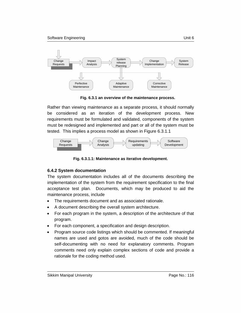
Software Maintenance
Maintenance refers to the support phase of software development.
Maintenance focuses on CHANGE associated with error correction,
adaptations required as the software environment evolves, and changes
due to enhancements brought about by changing customer requirements or
improved capability on the part of developers. Four types of maintenance
are typically encountered.
Correction
Even with the best quality assurance activities, it is likely that the customer
will uncover defects in the software. Corrective maintenance changes the
software to correct defects.
Adaption
Overtime, the original environment (e.g., CPU, operating system, business
rules, external product characteristics) for which the software was
Software Engineering Unit 2
Sikkim Manipal University Page No.: 11
developed is likely to change. Adaptive Maintenance results in modification
to the software to accommodate changes to its external environment.
Enhancement
As software is used, the customer/user will recognize additional functions
that will provide benefit. Perfective Maintenance extends the software
beyond its original functional requirements. Developers can also initiate
enhancements by utilizing their experience on similer project and replicating
the same on earlier developed systems.
Self Assessment Questions
1. Define Software Engineering ?
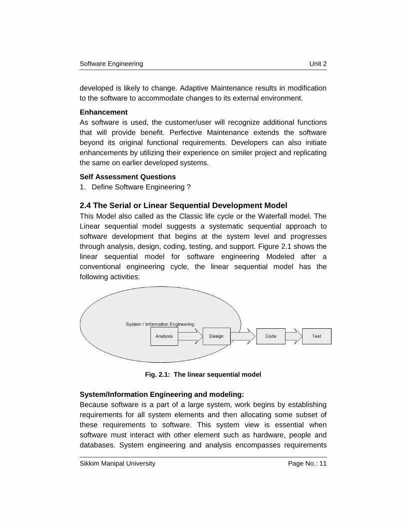
2.4 The Serial or Linear Sequential Development Model
This Model also called as the Classic life cycle or the Waterfall model. The
Linear sequential model suggests a systematic sequential approach to
software development that begins at the system level and progresses
through analysis, design, coding, testing, and support. Figure 2.1 shows the
linear sequential model for software engineering Modeled after a
conventional engineering cycle, the linear sequential model has the
following activities:
Fig. 2.1: The linear sequential model
System/Information Engineering and modeling:
Because software is a part of a large system, work begins by establishing
requirements for all system elements and then allocating some subset of
these requirements to software. This system view is essential when
software must interact with other element such as hardware, people and
databases. System engineering and analysis encompasses requirements
Software Engineering Unit 2
Sikkim Manipal University Page No.: 12
gathering at the system level with a small amount of top level design and
analysis. Information engineering encompasses requirements gathering at
the strategic business level and at the business area level.
Software requirement analysis
The requirement gathering process is intensified and focused specifically on
software. To understand the nature of the program to be built, the software
engineer (analyst) must understand the information domain for the software,
as well as required function, behavior, performance and interface.
Requirements for the both system and the software are documented and
reviewed with the customer.
Design
Software design is actually a multistep process that focuses on four distinct
attributes of a program, data structure, software architecture, interface
representations, and procedural (algorithmic) detail. The design process
translates requirements into a representation of the software that can be
assessed for quality before coding begins. Like requirements, the design is
documented and becomes part of the software configuration.
Code Generation
The design must be translated into a machine–readable form. The code
generation step performs this task. If design is performed in a detailed
manner, code generation can be accomplished mechanistically.
Testing
Once code has been generated, program testing begins. The testing
process focuses on the logical internals of the software, ensuring that all
statements have been tested, and on the functional externals; that is,
conducting tests to uncover errors and ensure that defined input will
produce actual results that agree with required results.
Support
Software will undergo change after it is delivered to the customer. Change
will occur because errors have been encountered, because the software
must be adopted to accommodate changes in its external environments or
because the customer requires functional or performance enhancements.
Software maintenance re-applies each of the preceding phases to an
existing program rather than a new one.
Software Engineering Unit 2
Sikkim Manipal University Page No.: 13
A successful software product is one that satisfies all the objectives of the
development project. These objectives include satisfying the requirements
and performing the development within time and cost constraints.
Generally, for any reasonable size projects, all the phases listed in the
model must be performed explicitly and formally.
The second reason is the one that is now under debate. For many projects
the linear ordering of these phases is clearly the optimum way to organize
these activities. However some argue that for many projects this ordering of
activity is unfeasible or suboptimal. Still waterfall model is conceptually the
simplest process model for software development that has been used most
often.
Limitation of the linear sequential model
1. The linear sequential model or waterfall model assumes the requirement
of a system which can be frozen (baseline) before the design begins.
This is possible for systems designed to automate an existing manual
system. But for a new system, determining the requirements is difficult
as the user does not even know the requirements. Hence, having
unchanging requirements is unrealistic for such projects.
2. Freezing the requirements usually requires choosing the hardware
(because it forms a part of the requirement specifications) A large
project might take a few years to complete. If the hardware is selected
early, then due to the speed at which hardware technology is changing ,
it is likely the final software will use a hardware technology on the verge
of becoming obsolete. This is clearly not desirable for such expensive
software systems.
3. The waterfall model stipulates that the requirements be completely
specified before the rest of the development can proceed. In some
situations it might be desirable to first develop a part of the system
completely and then later enhance the system in phases. This is often
done for software products that are developed not necessarily for a
client, but for general marketing, in which case the requirements are
likely to be determined largely by the developers themselves.
4. It is a document driven process that requires formal documents at the
end of each phase. This approach tends to make the process
documentation-heavy and is not suitable for many applications,
particularly interactive application, where developing elaborate
Software Engineering Unit 2
Sikkim Manipal University Page No.: 14
documentation of the user interfaces is not feasible. Also, if the
development is done using fourth generation language or modern
development tools, developing elaborate specifications before
implementation is sometimes unnecessary.
Despite these limitations, the serial model is the most widely used process
model. It is well suited for routine types of projects where the requirements
are well understood. That is if the developing organization is quite familiar
with the problem domain and requirements for the software are quite clear,
the waterfall model or serial model works well.
RAD Model
Rapid Application Development (RAD) is an incremental software
development process model that emphasizes an extremely short
development cycle. The RAD model is a high speed adaptation of the linear
sequential model in which the rapid development is achieved by using
component-based construction. If requirements are clear and well
understood and the project scope is constrained, the RAD process enables
a development team to create a fully functional system within a very short
period of time.
The RAD approach encompasses the following phases:
Business modeling
Here we try to find answers to questions like what information drives the
business process? What information is generated? Who generates it?
Where does the information go? Who processes it? Etc.,
Data modeling: Here the information flow which would have been defined
as part of the business modelling phase is refined into a set of data objects
that are needed to support the business.
Process modeling
The data objects defined in the data modelling phase are transformed to
achieve the information flow necessary to implement a business function.
Processing descriptions are created for adding, modifying, deleting, or
retrieving a data object.
Application generation:
RAD assumes the use of fourth generation techniques. Rather than creating
software using conventional third generation programming languages the
Software Engineering Unit 2
Sikkim Manipal University Page No.: 15
RAD process works to reuse existing program components(when possible)
or create reusable components(when necessary). In all cases, automated
tools are used to facilitate construction of the software.
Testing and turnover
Since the RAD process emphasizes reuse, many of the program
components have already been tested. This reduces overall testing time.
However, new components must be tested and all interfaces must be fully
exercised.
Drawbacks of the RAD model:
For large but scalable projects, RAD requires sufficient human resources
to create the right number of RAD teams.
RAD requires developers and customers who are committed to the
rapid-fire acitivites necessary to get a system complete in a much
abbreviated time frame. If commitment is lacking from either, RAD
projects will fail.
Not all types of applications are appropriate for RAD. If a system cannot
be properly modularized, building the components necessary for RAD
will be problematic. If high performance is an issue and performance is
to be achieved through tuning the interfaces to system components, the
RAD approach may not work.
RAD is not appropriate when technical risks are high. This occurs when
a new application makes a heavy use of new technology or when the
new software requires a high degree of interoperability with existing
computer programs.
Self Assessment Questions
1. Explain the drawbacks of the RAD model ?
2.5 Iterative Development Model
The iterative enhance model counters the third limitation of the waterfall
model and tries to combine a benefit of both prototyping and the waterfall
model. The basic idea is that the software should be developed in
increments, each increment adding some functional capability to the system
until the full system is implemented. At each step, extensions and design
modifications can be made. An advantage of this approach is that it can
result in better testing because testing each increment is likely to be easier
Software Engineering Unit 2
Sikkim Manipal University Page No.: 16
than testing the entire system as in the waterfall model. The increment
models provide feedback to the client i.e., useful for determining the final
requirements of the system.
In the first step of this model, a simple initial implementation is done for a
subset of the overall problem. This subset is one that contains some of the
key aspects of the problem that are easy to understand and implement and
which form a useful and usable system. A project control list is created that
contains, in order, all the tasks that must be performed to obtain the final
implementation. This project control list gives an idea of how far the project
is at any given step from the final system.
Each step consists of removing the next task from the list, designing the
implementation for the selected task, coding and testing the implementation,
performing an analysis of the partial system obtained after this step, and
updating the list as a result of the analysis. These three phases are called
the design phase, implementation phase and analysis phase. The process
is integrated until the project control list is empty, at which time the final
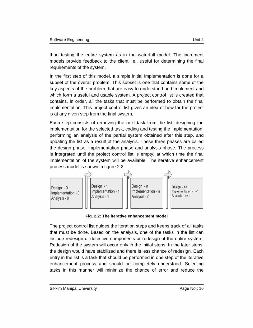
implementation of the system will be available. The iterative enhancement
process model is shown in figure 2.2.
Fig. 2.2: The iterative enhancement model
The project control list guides the iteration steps and keeps track of all tasks
that must be done. Based on the analysis, one of the tasks in the list can
include redesign of defective components or redesign of the entire system.
Redesign of the system will occur only in the initial steps. In the later steps,
the design would have stabilized and there is less chance of redesign. Each
entry in the list is a task that should be performed in one step of the iterative
enhancement process and should be completely understood. Selecting
tasks in this manner will minimize the chance of error and reduce the
Software Engineering Unit 2
Sikkim Manipal University Page No.: 17
redesign work. The design and implementation phases of each step can be
performed in a top-down manner or by using some other technique.
One effective use of this type of model is for product development, in which
the developers themselves provide the specifications and therefore have a
lot of control on what specifications go in the system and what stay out.
In a customized software development, where the client has to essentially
provide and approve the specifications, it is not always clear how this
process can be applied. Another practical problem with this type of
development project comes in generating the business contract-how will the
cost of additional features be determined and negotiated, particularly
because the client organization is likely to be tied to the original vendor who
developed the first version. Overall, in these types of projects, this process
model can be useful if the “core” of the applications to be developed is well
understood and the “increments” can be easily defined and negotiated. In
client-oriented projects, this process has the major advantage that the
client’s organization does not have to pay for the entire software together, it
can get the main part of the software developed and perform cost-benefit
analysis for it before enhancing the software with more capabilities.
2.6 The incremental Development Model
The incremental model combines elements of the linear sequential model
with the iterative of prototyping. Figure 2.3 shows the incremental model
applies linear sequences in a staggered fashion as calendar time
progresses. Each linear sequence produces a deliverable “increment” of the
software. For e.g., word processing software developed using the
incremental paradigm might deliver basic file management, editing, and
document production functions in the first increment; more sophisticated
editing and document production capabilities in the second increment;
spelling and grammar checking in the third increment; and advanced page
layout capability in the fourth increment. It should be noted that the process
flow for any increment could incorporate the prototyping paradigm.
Software Engineering Unit 2
Sikkim Manipal University Page No.: 18
Fig. 2.3: The incremental model
When an incremental model is used, the first increment is a core product.
That is, basic requirements are addressed, but many supplementary
features remain undelivered. The customer uses the core product. As a
result of use and/or evaluation, a plan is developed for the next increment.
The plan addresses the modification of the core product to better meet the
needs of the customer and the delivery of additional features and
functionality. This process is repeated following the delivery of each
increment, until the complete product is produced. The incremental process
model is iterative in nature. The incremental model focuses on the delivery
of an operational product with each increment.
Incremental development is particularly useful when staffing is unavailable
for a complete implementation by the business deadline that has been
established for the project. Early increments can be implemented with fewer
people. If the core product is well received, then additional staff can be
added to implement the next increment. In addition increments can be
planned to manage technical risks. For e.g.: a major system might require
the availability of new hardware i.e., under development and whose delivery
date is uncertain. It might be possible to plan early increments in a way that
avoids the use of this hardware, thereby enabling partial functionality to be
delivered to end users - without inordinate delay.
Software Engineering Unit 2
Sikkim Manipal University Page No.: 19
Spiral model
This model couples the iterative nature of the prototyping with the controlled
and systematic aspects of the linear sequential model. It provides the
potential for rapid development of incremental versions of the software.
Using the spiral model, software is developed in a series of incremental
releases. During early iterations, the incremental release might be a paper
model or prototype. During later iterations, increasingly more complete
versions of the engineered system are produced.
Usually the spiral model consists of around six task regions or phases.
Customer communication: tasks required to establish effective
communication between developer and customer.
Planning: tasks required to define resources, timelines, and other project-
related information.
Risk analysis: tasks required to assess both technical and management
risks.
Engineering: tasks required to build one or more representations of the
application.
Construction and release: tasks required to construct, test, install and
provide user support. (e.g. documentation and training).
Customer evaluation: tasks required to obtain customer feedback based
on evaluation of the software representations created during the engineering
stage and implemented during the installation stage.
As the evolutionary process begins, the software engineering team moves
around the spiral in a clockwise direction, beginning at the center. The first
circuit around the spiral might result in the development of a product
specification; subsequent circuit passes around the spiral might be used to
develop a prototype and then progressively more spohesticated versions of
the software. Each passes through the planning region resulting in
adjustments to the project plan. Cost and schedule are adjusted based on
feedback derived from customer evaluation. In addition, the project manager
adjusts the planned number of iterations required to complete the software.
Software Engineering Unit 2
Sikkim Manipal University Page No.: 20
Self Assessment Questions
1. Explain the Spiral Model.
2.7 The Parallel or Concurrent Development Model
The concurrent process model can be represented schematically as a series
of major technical activities, tasks, and their associated states. For e.g.:, the
engineering activity defined for the spiral model is accomplished by invoking
the following tasks. Prototyping and / or analysis modeling, requirements
specification, and design.
Figure 2.4 shows that it provides a schematic representation of one activity
with the concurrent process model. The activity-analysis-may be in any one
of the states noted at any given time. Similarly, other activities (e.g. Design
or customer communication) can be represented in an analogous manner.
All activities exist concurrently but reside in different states. For e.g., early in
a project the customer communication activity has completed its first
iteration and exists in the awaiting Changes State. The analysis activity
(which existed in the none state while initial customer communication was
completed) now makes a transition into the under development state. If the
customer indicates that changes in requirements must be made, the
analysis activity moves from the under development state into the
awaiting changes state.
The concurrent process model defines a series of events that will trigger
transition from state to state for each of the software engineering activities.
For e.g., during early stages of design, an inconsistency in the analysis
model is uncovered. This generates the event analysis model correction,
which will trigger the analysis activity from the done state into the awaiting
Changes State.
Software Engineering Unit 2
Sikkim Manipal University Page No.: 21
Fig. 2.4: One element of concurrent process model
The concurrent process model is often used as the paradigm for the
development of client/server applications. A client/server system is
composed of a set of functional components. When applied to client/server,
the concurrent process model defines activities in two dimensions a system
dimension and component dimension. System level issues are addressed
using three activities, design assembly, and use. The component dimension
addressed with two-activity design and realization. Concurrency is achieved
in two ways; (1) System and component activities occur simultaneously and
can be modeled using the state – oriented approach (2) a typical client
server application is implemented with many components, each of which
can be designed and realized concurrently.
The concurrent process model is applicable to all types of software
development and provides an accurate picture of the current state of a
project. Rather than confining software-engineering activities to a sequence
Software Engineering Unit 2
Sikkim Manipal University Page No.: 22
of events, it defines a net work of activities. Each activity on the network
exists simultaneously with other activities. Events generated within a given
activity or at some other place in the activity network trigger transitions
among the sates of an activity.
Component based development model:
This model incorporates the characteristics of the spiral model. It is
evolutionary in nature, demanding an iterative approach to the creation of
software. However, the component-based development model composes
applications from prepackaged software components called classes.
Classes created in past software engineering projects are stored in a class
library or repository. Once candidate classes are identified, the class library
is searched to determine if these classes already exist. If they do, they are
extracted from the library and reused. If a candidate class does not reside in
the library, it is engineered using object-oriented methods. The first iteration
of the application to be built is then composed using classes extracted from
the library and any new classes built to meet the unique needs of the
application. Process flow then returns to the spiral and will ultimately
re-enter the component assembly iteration during subsequent passes
through the engineering activity.
The component based development model leads to software reuse, and
reusability provides software engineers with a number of measurable
benefits although it is very much dependent on the robustness of the
component library.
2.8 Hacking
The growing dependence of society on software also places tremendous
social responsibilities on the shoulders of software engineers and their
managers. When the software is being used to monitor the health of
patients, control nuclear power plants, apply the breaks in an automobile,
transfer billions of dollars in an instant, launch missiles, or navigate an
airplane, it is not simply good engineering to build reliable software; it is also
the engineer’s ethical responsibilities to do so.
Program defects are not merely inconvenient “bugs” or interesting technical
puzzles to be captured, but potentially serious business-or life-threatening
errors. Building reliable software is technical objective of the software
Software Engineering Unit 2
Sikkim Manipal University Page No.: 23
engineer, but it also has ethical and social implications that must guide the
actions of a serious professional. In this light, “ Hacking”, i.e., inserting “play
full” bugs into programs, creating viruses, writing quick and dirty code just to
meet a schedule or a market window, shipping defective software, and even
shipping software that works but does not meet the agreed upon
specifications is unethical.
2.9 Summary
Software engineering is a discipline that integrates process, methods
and tools for the development of computer software.
The software process models consist of activities, which are involved, in
developing software products. Basic activities are software specification,
development, validation and evolution.
The linear sequential model of the software process considers each
process activity as a separate and discrete phase.
The evolutionary development model such as iterative, increment model
of the software process treats specification, development and validation
as concurrent activities.
2.10 Terminal Questions
1. Explain whether the linear sequential model of the software process is
an accurate reflection of software development activities or not.
2. Giving reason for your answer based on the system being developed
suggest the most appropriate generic software process model which
might be used as a basic for managing the development of the following
systems;
a) a system to control anti-lock barking in a car;
b) a virtual reality system to support software maintenance;
c) a university accounting system which is intended to replace an
existing system;
d) an interactive system which allows railway passenger to find train
times from terminals installed in stations.
Software Engineering Unit 2
Sikkim Manipal University Page No.: 24
3. Which of the software engineering paradigms presented in this chapter
do you think would be most effective? Why?
4. Describe the concurrent development model in your own words.
2.11 Answers to Terminal Questions
1. Refer to section 2.4
2. Refer to sections 2.4 to 2.6
3. Refer to section 2.7
Software Engineering Unit 3
Sikkim Manipal University Page No.: 25
Unit 3 Software Reliability
Structure
3.1 Introduction
Objectives
Self Assessment Questions
3.2 Software reliability metrics
Self Assessment Questions
3.3 Programming for Reliability
3.3.1 Fault avoidance
3.3.2 Fault tolerance
Self Assessment Questions
3.4 Software Reuse
3.5 Summary
3.6 Terminal Questions
3.6 Answers to Self Assessment Questions
3.1 Introduction
Reliability is the most important dynamic characteristic of almost all software
systems. Unreliable software results in high costs for end-users.
Developers of unreliable systems may acquire a bad reputation for quality
and lose future business opportunities.
The Reliability of a software system is a measure of how well users think it
provides the services that they require. Reliability is usually defined as the
probability of failure-free operation for a specified time in a specified
environment for a specific purpose. Say it is claimed that software installed
on an aircraft will be 99.99% reliable during an average flight of five hours.
This means that a software failure of some kind will probably occur in one
flight out of 10000.
A formal definition of reliability may not equate to user’s experience of the
software. The difficulty in relating such a figure to user’s experience arises
because it does not take the nature of the failure into account. A user does
not consider all services to be of equal importance. A system might be
thought of as unreliable if it ever failed to provide some critical service. For
example, say a system was used to control braking on an aircraft but failed
Software Engineering Unit 3
Sikkim Manipal University Page No.: 26
to work under a single set of very rare conditions. If an aircraft crashed
because of these failure conditions, pilots of similar aircraft would regard the
software as unreliable.
There is a general requirement for more reliable systems in all application
domains. Customers expect their software to operate without failure to be
available when it is required. Improved programming techniques, better
programming languages and better quality management have led to very
significant improvements in reliability for most software. However, for some
systems, such as those which control unattended machinery, these ‘normal’
techniques may not be enough to achieve the level of reliability required, In
these cases special programming techniques may be necessary to
achieve the required reliability. Some of these techniques are discussed
in this chapter.
The concept on Software reuse has been included in the following section.
Because improved reliability is one of the benefits of reuse. Software
components are not just used in one system but are tried and tested in a
variety of different environments. Design and implementation forms are
discovered and eliminated so the reusable components contain few errors.
Although absolute reliability specification is impossible, reusable
components may have an associative quality certification. This allows
reusers to incorporate them with confidence in their systems.
Objectives
Upon Completion of this Unit, you should be able to:
Explain what basically meant software Reliability
Know more about reliability metrics
Know about Statistical analysis and programming for reliability
Software reliability
Software reliability is a function of the number of failures experienced by a
particular user of that software. A software failure occurs when the software
is executing. It is a situation in which the software does not deliver the
service expected by the user. Software failures are not the same as
software faults although these terms are often used interchangeably.
Software Engineering Unit 3
Sikkim Manipal University Page No.: 27
Formal specifications and proof do not guarantee that the software will be
reliable in practical use. The reasons for this are:
(1) The specifications may not reflect the real requirements of system
users many failures experienced by users were a consequence of
specification errors and omissions, which could not be detected by
formal system specification. It may even be the case that the
opaqueness of formal notations makes it more difficult for users to
establish whether or not a system meets their real requirements.
(2) The proof may contain errors Program proofs are large and complex
so, like large and complex programs, they usually contain errors.
(3) The Proof may assume a usage pattern, which is incorrect. If the
system is not used as anticipated, the proof may be invalid.
Fig. 3.0: Shows cost Vs Reliability
Because of additional design, implementation and validation overheads,
increasing reliability can dramatically increase development costs. Figure
3.0 shown above is the relationship between costs and incremental
improvements in reliability.
If it is possible to measure if a system is 100% reliable as this would require
an amount of time equal to the lifetime of the system. However, as reliability
requirements increase, system costs usually rise exponentially. This is
mostly due to the need of redundant hardware and a vast increase in testing
costs to check that the required reliability has been achieved. As discussed
Software Engineering Unit 3
Sikkim Manipal University Page No.: 28
some specifications, which call for, ultra-reliable systems are unrealistic.
The number of tests required to validate these specifications cannot be
carried out in a reasonable time.
There is, of course, an efficiency penalty, which must be paid for increasing
reliability. Reliable software must include extra, often redundant, code to
perform the necessary checking for exceptional conditions. This reduces
program execution speed and increases the amount of store required by the
program. Reliability should always take precedence over efficiency for the
following reasons:
1) Computers are now cheap and fast: There is little need to maximize
equipment usage. Paradoxically, however, faster equipment leads to
increasing expectations on the part of the user so efficiency
considerations cannot be completely ignored.
2) Unreliable software is liable to be discarded by users: If a company
attains a reputation for unreliability because of single unreliable product,
it is likely to affect future sales of all of that company’s products.
3) System failure costs may be enormous: For some applications, such
a reactor control system or an aircraft navigation system, the cost of
system failure is orders of magnitude greater than the cost of the control
system.
4) Unreliable systems are difficult to improve: It is usually possible to
tune an inefficient system because most execution time is spent in small
program sections. An unreliable system is more difficult to improve as
unreliability tends to be distributed throughout the system.
5) Inefficiency is predictable: Programs take a long time to execute and
users can adjust their work to take this into account. Unreliability, by
contrast, usually surprises the user. Software that is unreliable can have
hidden errors which can violate system and user data without warning
and whose consequences are not immediately obvious. For example, a
fault in a CAD program used to design aircraft might not be discovered
until several plane crashers occurs.
6) Unreliable systems may cause information loss: Information is very
expensive to collect and maintains; it may sometimes be worth more
than the computer system on which it is processed. A great deal of effort
Software Engineering Unit 3
Sikkim Manipal University Page No.: 29
and money is spent duplicating valuable data to guard against data
corruption caused by unreliable software.
The software process used to develop that product influences the reliability
of the software product. A repeatable process, which is oriented towards
defect avoidance, is likely to develop a reliable system. However, there is
not a simple relationship between product and process reliability.
Users often complain that systems are unreliable. This may be due to poor
software engineering. However, a common cause of perceived unreliability
is incomplete specifications. The system performs as specified but the
specifications do not set out how the software should behave in exceptional
situations. As professionals, software engineers must do their best to
produce reliable systems, which take meaningful and useful actions in such
situations.
Self Assessment Questions
1. What is Software reliability ?
2. Why reliability is more important than efficiency ?
3.2 Software reliability Metrics
Metrics which have been used for software reliability specification are shown
in Figure 3.1 shown below .The choice of which metric should be used
depends on the type of system to which it applies and the requirements of
the application domain. For some systems, it may be appropriate to use
different reliability metrics for different sub-systems.
Software Engineering Unit 3
Sikkim Manipal University Page No.: 30
Fig. 3.1: Reliability matrix
In some cases, system users are most concerned about how often the
system will fail, perhaps because there is a significant cost in restarting the
system. In those cases, a metric based on a rate of failure occurrence
(ROCOF) or the mean time to failure should be used.
In other cases, it is essential that a system should always meet a request for
service because there is some cost in failing to deliver the service. The
number of failures in some time period is less important. In those cases, a
metric based on the probability of failure on demand (POFOD) should be
used. Finally, users or system operators may be mostly concerned that the
system is available when a request for service is made. They will incur some
loss if the system is unavailable. Availability (AVAIL). Which takes into
account repair or restart time, is then the most appropriate metric.
Software Engineering Unit 3
Sikkim Manipal University Page No.: 31
There are three kinds of measurement, which can be made when assessing
the reliability of a system:
1) The number of system failures given a number of systems inputs. This
is used to measure the POFOD.
2) The time (or number of transaction) between system failures. This is
used to measure ROCOF and MTTF.
3) The elapsed repair or restart time when a system failure occurs. Given
that the system must be continuously available, this is used to measure
AVAIL.
Time is a factor in all of this reliability metrics. It is essential that the
appropriate time units should be chosen if measurements are to be
meaningful. Time units, which may be used, are calendar time, processor
time or may be some discrete unit such as number of transactions.
Software reliability specification
System requirements documents, reliability requirements are expressed in
an informal, qualitative, untestable way. Ideally, the required level of
reliability should be expressed quantitatively in the software requirement
specification. Depending on the type of system, one or more of the metrics
discussed in the previous section may be used for reliability specifications.
Statistical testing techniques (discussed later) should be used to measure
the system reliability. The software test plan should include an operational
profile of the software to assess its reliability.
The steps involved in establishing a reliability specification are as follows:
1) For each identified sub-system, identify the different types of system
failure, which may occur and analyze the consequences of these
failures.
2) From the system failure analysis, partition failures into appropriate
classes. A reasonable starting point is to use the failure types shown in
Figure 3.1.1 shown below. For each failure class identified, define the
reliability requirement using the appropriate reliability metric. It is not
necessary to use the same metric for different classes of failure. For
example, where a failure requires some intervention to recover from it,
the probability of that failure occurring on demand might be the most
appropriate metric. When automatic recover is possible and the effect of
Software Engineering Unit 3
Sikkim Manipal University Page No.: 32
the failure is some user inconvenience, ROCOF might be more
appropriate.
Failure Class Description
Transient Occurs only with certain inputs
Permanent Occurs with all inputs
Recoverable System can recover without operator intervention
Unrecoverable Operator intervention needed to recover from failure
Non-corrupting Failure does not corrupt system state or data
Corrupting Failure corrupts system state or data.
Fig. 3.1.1: Failure classification
The cost of developing and validating a reliability specification for software
system is very high.
Statistical testing
Statistical testing is a software testing process in which the objective is to
measure the reliability of the software rather than to discover software faults.
It users different test data from defect testing, which is intended to find faults
in the software.
The steps involved in statistical testing are:
1) Determine the operational profile of the software. The operational profile
is the probable pattern of usage of the software. This can be determined
by analyzing historical data to discover the different classes of input to
the program and the probability of their occurrence.
2) Select or generate a set of test data corresponding to the operational
profile.
3) Apply these test cases to the program, recording the amount of
execution time between each observed system failure. It may not be
appropriate to use raw execution time. As discussed in the previous
section, the time units chosen should be appropriate for the reliability
metric used.
4) After a statistically significant number of failures have been observed,
the software reliability can then be computed. This involves using the
Software Engineering Unit 3
Sikkim Manipal University Page No.: 33
number of failures detected and the time between these failures to
computer the required reliability metric.
This approach to reliability estimation is not easy to apply in practice. The
difficulties, which arise, are due to:
Operational profile uncertainty;
High cost of operational profile generation;
Statistical uncertainty when high reliability is specified.
Self Assessment Questions
1. How to establish a software reliability specification ?
2. What is statistical testing ?
3.3 Programming for Reliability
There is a general requirement for more reliable systems in all application
domains. Customers expect their software to operate without failures and to
be available when it is required. Improved programming techniques, better
programming languages and better quality management have led to very
significant improvements in reliability for most software. However, for some
systems, such as those, which control unattended machinery, these ‘normal’
techniques may not be enough to achieve the level of reliability required. In
these cases, special programming techniques may be necessary to achieve
the required reliability. Some of these techniques are discussed in this
chapter.
Reliability in a software system can be achieved using three strategies:
Fault avoidance: This is the most important strategy, which is
applicable to all types of system. The design and implementation
process should be organized with the objective of producing fault-free
systems.
Fault tolerance: This strategy assumes that residual faults remain in the
system. Facilities are provided in the software to allow operation to
continue when these faults cause system failures.
Fault detection: Faults are detected before the software is put into
operation. The software validation process uses static and dynamic
methods to discover any faults, which remain in a system after
implementation.
Software Engineering Unit 3
Sikkim Manipal University Page No.: 34
3.3.1 Fault avoidance
A good software process should be oriented towards fault avoidance rather
than fault detection and removal. It should have the objective of developing
fault-free software. Fault-free software means software, which conforms to
its specification. Of course, there may be errors in the specification or it
may not reflect the real needs of the user so fault-free software does not
necessarily mean that the software will always behave as the user wants.
Fault avoidance and the development of fault-free software relies on :
1. The availability of a precise system specification, which is an
unambiguous description of what, must be implemented.
2. The adoption of an organizational quality philosophy in which quality is
the driver of the software process. Programmers should expect to write
bug-free program.
3. The adoption of an approach to software design and implementation
which is based on information hiding and encapsulation and which
encourages the production of readable programs.
4. The use of a strongly typed programming language so that possible
errors are detected by the language compiler.
5. Restriction on the use of programming construct, such as pointers,
which are inherently error-prone.
Achieving fault-free software is virtually impossible if low-level programming
Languages with limited type checking are used for program development.
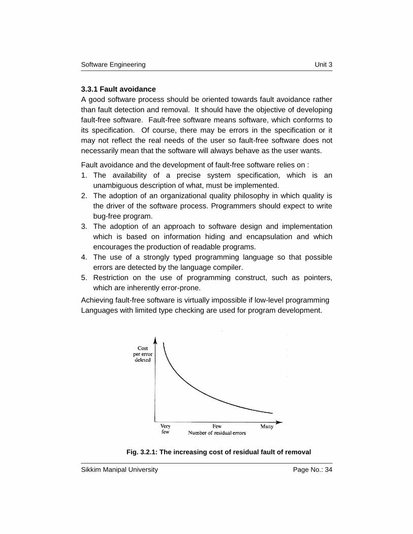
Fig. 3.2.1: The increasing cost of residual fault of removal
Software Engineering Unit 3
Sikkim Manipal University Page No.: 35
We must be realistic and accept that human errors will always occur. Faults
may remain in the software after development. Therefore, the development
process must include a validation phase, which checks the developed
software for the presence of faults. This validation phase is usually very
expensive. As faults are removed from a program, the cost of finding and
removing remaining faults tends to rise exponentially. As the software
becomes more reliable, more and more testing is required to find fewer and
fewer faults.
Structured programming and error avoidance
Structured programming is term which is to mean programming without
using go to statements, programming using only while loops and if
statements as control constructs and designing using a top-down approach.
The adoption of structured programming was an important milestone in the
development of software engineering because it was the first step away
from an undisciplined approach to software development.
Go to statement was an inherently errorprone programming construct. The
disciplined use of control structures force programmers to think carefully
about their program. Hence they are less likely to make mistakes during
development. Structured programming means programs can be read
sequentially and are therefore easier to understand and inspect. However,
avoiding unsafe control statements is only the first step in programming for
reliability.
Faults are less likely to be introduced into programs if the use of these
constructs is minimized. These constructs include:
1) Floating-point numbers: Floating-point numbers are inherently
imprecise. They present a particular problem when they are compared
because representation imprecision may lead to invalid comparisons.
Fixed-point numbers, where a number is represented to a given number
of decimal places, are safer as exact comparisons are possible.
2) Pointer: Pointers are low-level constructs, which refer directly to areas
of the machine memory. They are dangerous because errors in their
use can be devastating and because they allow ‘aliasing’. This means
the same entity may be referenced using different names. Aliasing
makes programs harder to may be referenced using different names.
Software Engineering Unit 3
Sikkim Manipal University Page No.: 36
Alilasing makes programs harder to understand so that errors are more
difficult to find. However, efficiency requirements mean that it is often
impractical to avoid the use of pointers.
3) Dynamic memory allocation: Program memory is allocated at run-time
rather than compile-time. The danger with this is that the memory may
not be de-allocated so that the system eventually runs out of available
memory. This can be a very subtle type of errors to detect as the
system may run successfully for a long time before the problem occurs.
4) Parallelism: Parallelism is dangerous because of the difficulties of
predicting the subtle effects of timing interactions between parallel
process. Timing problems cannot usually e detected by program
inspection and the peculiar combination of circumstances, which cause
a timing problem, may not result during system testing. Parallelism may
be unavoidable but its use should be carefully controlled to minimize
inter-process dependencies. Programming language facilities, such as
Ada tasks, help avoid some of the problems of parallelism as the
compiler can detect some kinds of programming errors.
5) Recursion: Recursion is the situation in which a subroutine calls itself or
calls another subroutine, which then calls the calling subroutine. Its use
can result in very concise programs but it can be difficult to follow the
logic of recursive programs. Errors in using recursion may result in the
allocation of all they system’s memory as temporary stack variables are
created.
6) Interrupts: Interrupts are a means of forcing control to transfer to a
section of code irrespective of the code currently executing. The
dangers of this are obvious as the interrupt may cause a critical
operation to be terminated.
3.3.2 Fault tolerance
A fault-tolerant system can continue in operation after some system failures
have occurred. Fault tolerance is needed in situations where system failure
would cause some accident or where a loss of system operation would
cause large economic losses. For example, the computers in an aircraft
must continue in operation until the aircraft has landed; the computers in an
traffic control system must be continuously available.
Software Engineering Unit 3
Sikkim Manipal University Page No.: 37
Fault-tolerance facilities are required if the system is to failure. There are
four aspects to fault tolerance.
1. Failure detection: The system must detect a particular state
combination has resulted or will result in a system failure.
2. Damage assessment: The parts of the system state, which have been
affected by the failure, must be detected.
3. Fault recovery: The system must restore its state to a known ‘safe’
state. This may be achieved by correcting the damaged state or by
restoring the system the system to a known ‘safe’ state. Forward error
recovery is more complex as it involves diagnosing system faults and
knowing what the system state should have been had the faults not
caused a system failure.
4. Fault repair: This involves modifying the system so that the fault does
not recur. In many cases, software failures are transient and due to a
peculiar combination of system inputs. No repair is necessary as normal
processing can resume immediately after fault recovery. This is an
important distinction between hardware and software faults.
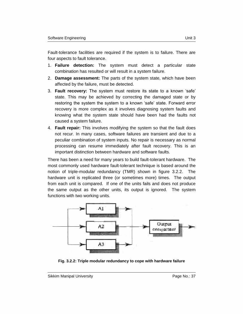
There has been a need for many years to build fault-tolerant hardware. The
most commonly used hardware fault-tolerant technique is based around the
notion of triple-modular redundancy (TMR) shown in figure 3.2.2. The
hardware unit is replicated three (or sometimes more) times. The output
from each unit is compared. If one of the units fails and does not produce
the same output as the other units, its output is ignored. The system
functions with two working units.
Fig. 3.2.2: Triple modular redundancy to cope with hardware failure
Software Engineering Unit 3
Sikkim Manipal University Page No.: 38
The weakness of both these approaches to fault tolerance is that they are
based on the assumption that the specification is correct. They do not
tolerate specification errors.
There have been two comparable approaches to the provision of software
fault tolerance. Both have been derived from the hardware model where a
component is replicated.
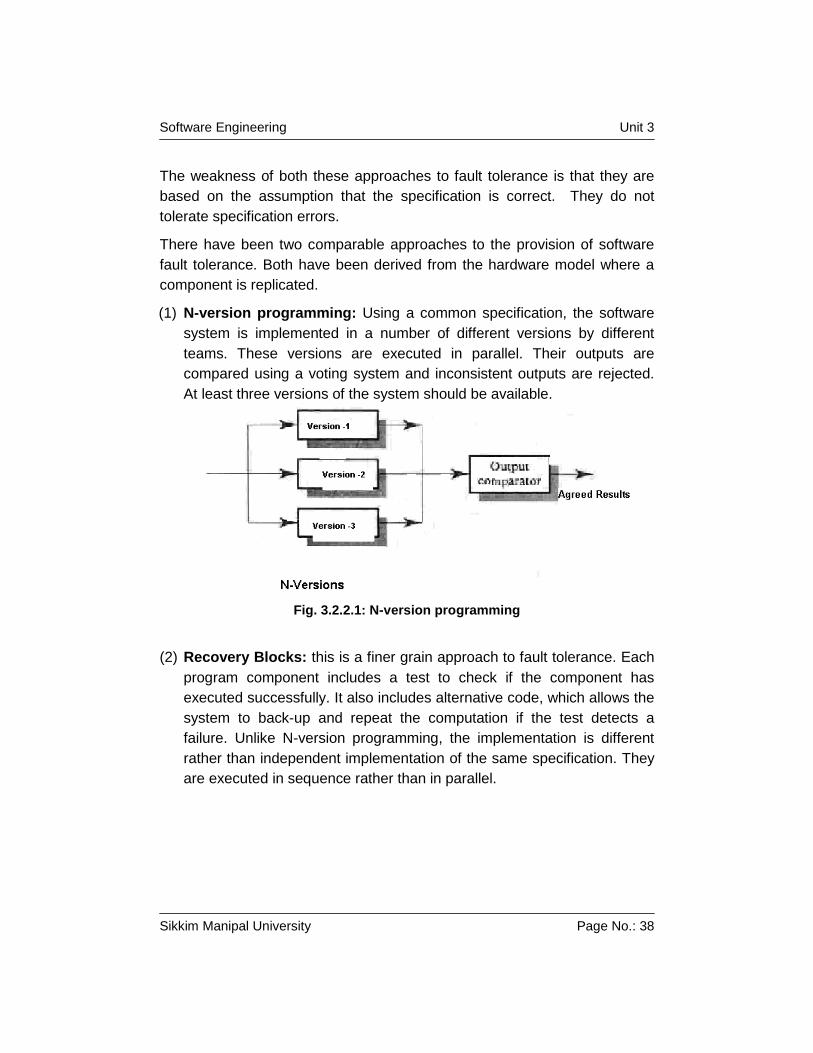
(1) N-version programming: Using a common specification, the software
system is implemented in a number of different versions by different
teams. These versions are executed in parallel. Their outputs are
compared using a voting system and inconsistent outputs are rejected.
At least three versions of the system should be available.
Fig. 3.2.2.1: N-version programming
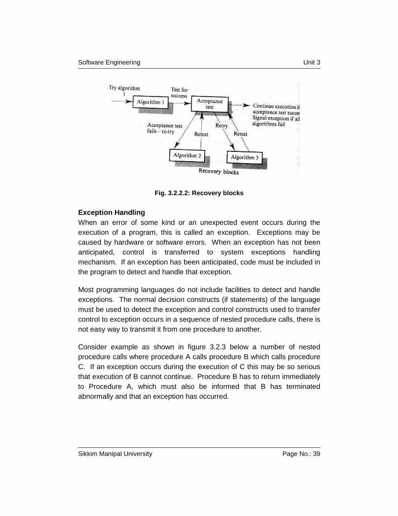
(2) Recovery Blocks: this is a finer grain approach to fault tolerance. Each
program component includes a test to check if the component has
executed successfully. It also includes alternative code, which allows the
system to back-up and repeat the computation if the test detects a
failure. Unlike N-version programming, the implementation is different
rather than independent implementation of the same specification. They
are executed in sequence rather than in parallel.
Software Engineering Unit 3
Sikkim Manipal University Page No.: 39
Fig. 3.2.2.2: Recovery blocks
Exception Handling
When an error of some kind or an unexpected event occurs during the
execution of a program, this is called an exception. Exceptions may be
caused by hardware or software errors. When an exception has not been
anticipated, control is transferred to system exceptions handling
mechanism. If an exception has been anticipated, code must be included in
the program to detect and handle that exception.
Most programming languages do not include facilities to detect and handle
exceptions. The normal decision constructs (if statements) of the language
must be used to detect the exception and control constructs used to transfer
control to exception occurs in a sequence of nested procedure calls, there is
not easy way to transmit it from one procedure to another.
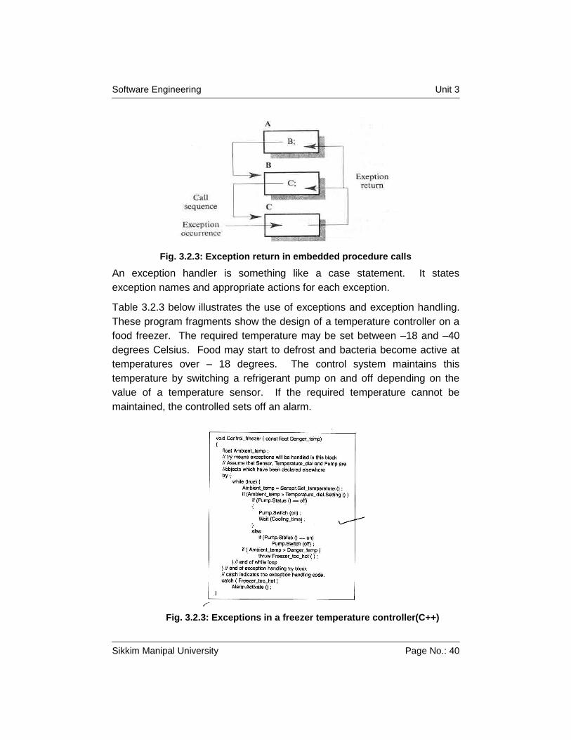
Consider example as shown in figure 3.2.3 below a number of nested
procedure calls where procedure A calls procedure B which calls procedure
C. If an exception occurs during the execution of C this may be so serious
that execution of B cannot continue. Procedure B has to return immediately
to Procedure A, which must also be informed that B has terminated
abnormally and that an exception has occurred.
Software Engineering Unit 3
Sikkim Manipal University Page No.: 40
Fig. 3.2.3: Exception return in embedded procedure calls
An exception handler is something like a case statement. It states
exception names and appropriate actions for each exception.
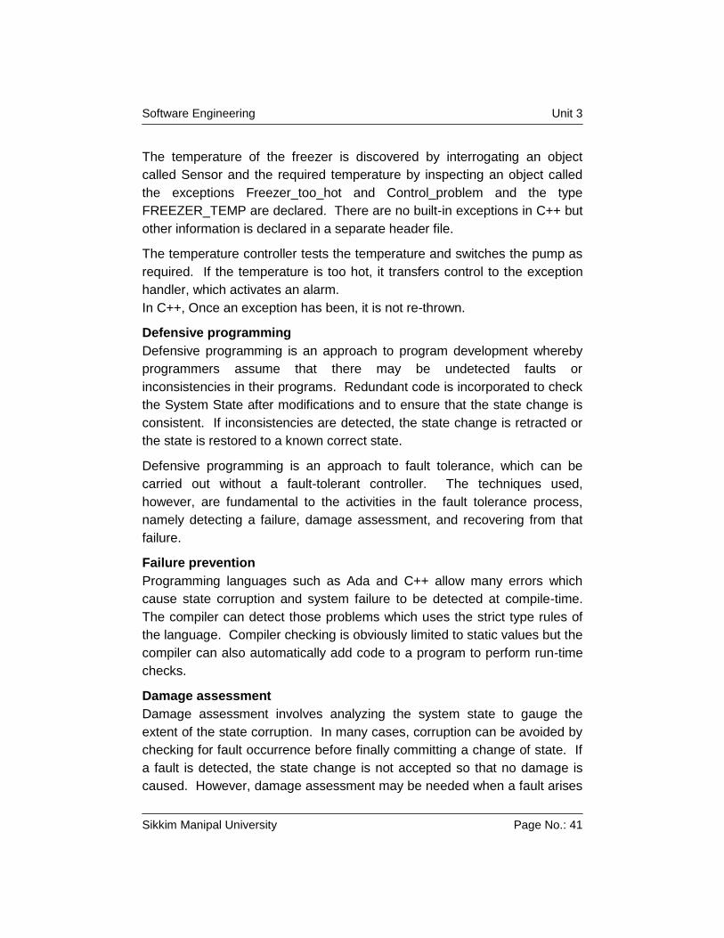
Table 3.2.3 below illustrates the use of exceptions and exception handling.
These program fragments show the design of a temperature controller on a
food freezer. The required temperature may be set between –18 and –40
degrees Celsius. Food may start to defrost and bacteria become active at
temperatures over – 18 degrees. The control system maintains this
temperature by switching a refrigerant pump on and off depending on the
value of a temperature sensor. If the required temperature cannot be
maintained, the controlled sets off an alarm.
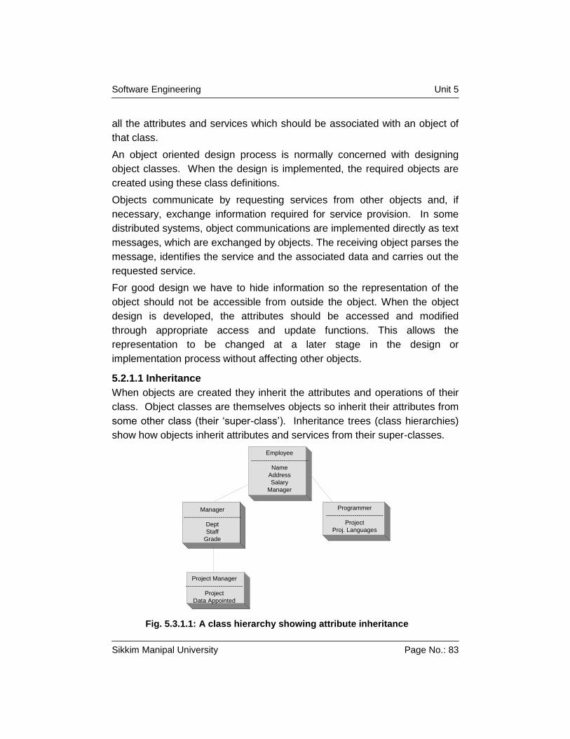
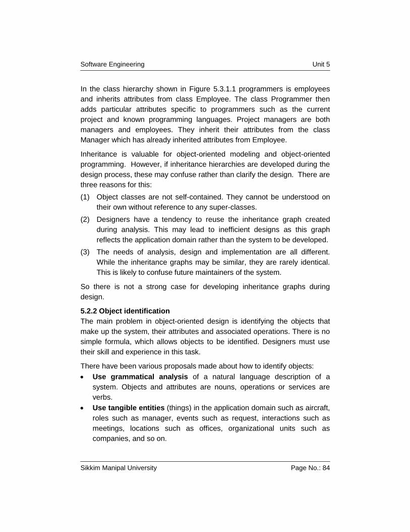
Fig. 3.2.3: Exceptions in a freezer temperature controller(C++)
Software Engineering Unit 3
Sikkim Manipal University Page No.: 41
The temperature of the freezer is discovered by interrogating an object
called Sensor and the required temperature by inspecting an object called
the exceptions Freezer_too_hot and Control_problem and the type
FREEZER_TEMP are declared. There are no built-in exceptions in C++ but
other information is declared in a separate header file.
The temperature controller tests the temperature and switches the pump as
required. If the temperature is too hot, it transfers control to the exception
handler, which activates an alarm.
In C++, Once an exception has been, it is not re-thrown.
Defensive programming
Defensive programming is an approach to program development whereby
programmers assume that there may be undetected faults or
inconsistencies in their programs. Redundant code is incorporated to check
the System State after modifications and to ensure that the state change is
consistent. If inconsistencies are detected, the state change is retracted or
the state is restored to a known correct state.
Defensive programming is an approach to fault tolerance, which can be
carried out without a fault-tolerant controller. The techniques used,
however, are fundamental to the activities in the fault tolerance process,
namely detecting a failure, damage assessment, and recovering from that
failure.
Failure prevention
Programming languages such as Ada and C++ allow many errors which
cause state corruption and system failure to be detected at compile-time.
The compiler can detect those problems which uses the strict type rules of
the language. Compiler checking is obviously limited to static values but the
compiler can also automatically add code to a program to perform run-time
checks.
Damage assessment
Damage assessment involves analyzing the system state to gauge the
extent of the state corruption. In many cases, corruption can be avoided by
checking for fault occurrence before finally committing a change of state. If
a fault is detected, the state change is not accepted so that no damage is
caused. However, damage assessment may be needed when a fault arises
Software Engineering Unit 3
Sikkim Manipal University Page No.: 42
because a sequence of state changes (all of which are individually correct)
causes the system to enter an incorrect state.
The role of the damage assessment procedures is not to recover from the
fault but to assess what parts of the state space have been affected by the
fault. Damage can only be assessed if it is possible to apply some ‘validity
function’, which checks if the state is consistent. If inconsistencies are
found, these are highlighted or signaled in some way.
Other techniques which can be used for fault detection and damage
assessment are dependent on the system state representation and on the
application . Possible methods are:
The use of checksums in data exchange and check digits in numeric
data;
The use of redundant links in data structures which contain pointers;
The use of watchdog timers in concurrent systems.
A checksum is a value that is computed by applying some mathematical
function to the data. The function used should give a unique value for the
packet of data, which is exchanged. The sender who applies the checksum
function to the data and appends that function value to the data computes
this checksum. The receiver applies the same function to the data and
compares the checksum values. If these differ, some data corruption has
occurred.
When linked data structures are used, the representation can be made
redundant by including backward pointers. That is, for every reference from
A to B, there exists a comparable reference from B to A. It is also possible
to keep count of the number of elements in the structure. Checking can
determine whether or not all pointers have an inverse value and whether or
not the stored size and the computed structure size are the same.
When processes must react within a specific time period, a watch-dog timer
may be installed. A watch-dog timer is a timer which must be reset by the
executing process after its action is complete. It is started at the same time
as a process and times the process execution. If, for some reason the
process fails to terminate, the watch-dog timer is not reset. The controller
can therefore detect that a problem has arisen and take action to force
process termination.
Software Engineering Unit 3
Sikkim Manipal University Page No.: 43
Fault recovery
Fault recovery is the process of modifying the state space of the system so
that the effects of the fault are minimized. The system can continue in
operation, perhaps in same degraded form. Forward recovery involves
trying to correct the damaged System State. Backward recovery restores
the System State to a known ‘correct’ state.
There are two general situations where forward error recovery can be
applied:
(1) When coded is corrupted The use of coding techniques which add
redundancy to the data allows errors to be corrected as well as
detected.
(2) When linked structures are corrupted if forward and backward
pointers are included in the data structure, the structure can be
recreated if enough pointers remain uncorrupted. This technique is
frequently used for file system and database repair.
Backward error recovery is a simpler technique, which restores the state to
a known safe state after an error has been detected. Most database
systems include backward error recovery. When a user initiates a database
computation a transaction is initiated. Changes made during that transaction
are not immediately incorporated in the database. The database is only
updated after the transaction is finished and no problems are detected. If
the transaction fails, the database is not updated.
Design by Contract
Meyer suggests an approach to design, called design by contract, to help
ensure that a design meets its specifications. He begins by viewing software
system as a set of communicating components whose interaction is based
on a precisely defined specification of what each component is supposed to
do. These specifications, called contracts, govern how the component is to
interact with other components and systems. Such specification cannot
guarantee correctness, but it forms a good basis for testing and validation.
Contract is written between two parties when one commissions the other for
a particular service or product. Each party expects some benefit for some
obligation; the supplier produces a service or product in a given period of
time in exchange for money, and the client accepts the service or product
for the money. The contract makes the obligation and benefits explicit.
Software Engineering Unit 3
Sikkim Manipal University Page No.: 44
Mayer applies the notion of a contract to software. A software component,
called a client, adopts a strategy to perform a set of tasks, t1, t2,……tn. In
turn, each nontrivial subtask, it is executed when the client calls another
component, the supplier, to perform it. That is a contract between the two
components to perform the sub-task. Each contract covers mutual obligation
(called preconditions), benefits (called postconditions), and consistency
constraints (called invariant). Together, these contract properties are called
assertions.
For example, suppose the client component has a table where each
element is identified by a character string used as a key. Our supplier’s
component’s task is to insert an element from the table into a dictionary of
limited size. We can describe the contract between the two components in
the following way.
1. The client component ensures that the dictionary is not full and that the
key is nonempty.
2. The supplier component records the element in table.
3. The client component accesses the updated table where the element
appears.
4. If the table is full or the key is empty, no action is taken.
Self Assessment Questions
1. What do you mean by fault avoidance.
2. Explain why fault tolerance facilities are required if the system is failure.
3. Generally in which situation fault recovery process is applied.
3.4 Software Reuse
The design process in most engineering disciplines is based on component
reuse. Mechanical or electrical engineers do not specify a design in which
every component has to be manufactured specially. They base their design
on components that have been tried and tested in other systems. These
components obviously include small components such as nuts and bolts.
However, they may also be major sub-systems such as engines,
condensers or turbines. By contrast, software system design usually
assumes that all components are to be implemented specially for the
system being developed. Apart from libraries such as window system
libraries, there is no common base of reusable software components, which
is known by all software engineers. However, this situation is slowly
Software Engineering Unit 3
Sikkim Manipal University Page No.: 45
changing. We need to reuse our software assets rather than redevelop the
same software again and again. Demands for lower software production
and maintenance costs along with increased quality can only be met by
widespread and systematic software reuse. Component reuse, of course,
does not just mean the reuse of code. It is possible to reuse specifications
and designs. The potential gains from reusing abstract products of the
development process, such as specifications, may be greater than those
from reusing code components. Code contains low-level detail, which may
specialize it to such an extent that it cannot be reused. Designs or
specifications are more abstract and hence more widely applicable.
The reuse of software can consider at a number of different levels:.
1) Application system reuse: The whole of an application system may be
reused. The key problem here is ensuring that the software is portable;
it should execute on several different platforms.
2) Sub-system reuse: Major sub-systems of an application may be
reused. For example, a pattern-matching system developed as part of a
text processing system may be reused in a database management
system.
3) Module or object reuse: Components of a system representing a
collection of functions may be reused. For example, an Ada package or
a C++ object implementing a binary tree may be reused in different
applications.
4) Function reuse: Software components, which implement a single
function, such as a mathematical function, may be reused.
Four aspects of software reuse:
5) Software development with reuses: What are the advantages and
problems of developing software with reusable components? How must
software process evolve to incorporate reuse?
6) Software development for reuse: How cans software components be
generalized so that they are usable across a range of systems?
7) Generator based reuse: How do application generators support the
reuse of domain concepts?
8) Application system reuses: How making them available on a range of
machines reuse can entire application systems? What implementation
strategies should be used to develop portable software?
Software Engineering Unit 3
Sikkim Manipal University Page No.: 46
3.4.1 Software development with reuse
Software development with reuse is an approach to development, which
tries to maximize the reuse of existing components. An obvious advantage
of this approach is that overall development costs should be reduced.
Fewer software components need be specified, designed, implemented and
validated. However, cost reduction is only one potential advantage of reuse.
Systematic reuse in the development process offers further advantages:
1) System reliability increased: Reused components, which have been
exercised in working systems, should be more reliable than new
components. These components have been tested in operational
systems and have therefore been exposed to realistic operating
conditions.
2) Overall process risk is reduced: If a component exists, there is less
uncertainty in the costs of reusing that component than in the costs of
development. This is an important factor for project management as it
reduces the uncertainties in project cost estimation. This is particularly
true when relatively large components such as sub-systems are reused.
3) Effective use can be made of specialists: Instead of application
specialists doing the same work on different projects, these specialists
can develop reusable components which encapsulate their knowledge.
4) Organizational standards can be embodied in reusable
components: Some standard, such as user interface standards, can be
implemented as a set of standard components. For example, reusable
components may be developed to implement menus in a user interface.
All applications present the same menu formats to users. The use of
standard user interfaces improves reliability, as users are less likely to
make mistakes when presented with a familiar interface.
5) Software development time can be reduced: Bringing a system to
market as early as possible is often more important than overall
development costs. Reusing component speeds up system production
because both development and validation time should be reduced.
Incorporating a specific reuse activity as shown in figure 3.3.1 below can
incorporate reuse into the systems development process. The system
designer completes a high-level design and specifications of the
components of that design. These specifications are used to find
Software Engineering Unit 3
Sikkim Manipal University Page No.: 47
components to reuse. These may be incorporated at the architectural level
or at more detailed design levels.
Design System Architecture Specify components Search for Reusable components Incorporate discovered components
Fig. 3.3.1: Reuse in a standard development process
Although this model can result in significant reuse, it contrasts with the
approach adopted in other engineering disciplines where reusability drives
the design process. Rather than design then search for reusable
components, engineers first search for reusable components. They base
their design on these components.
There are three conditions for software development with reuse:
1. It must be possible to find appropriate reusable components.
Organizations need a base properly catalogued and documented
reusable component. The cost of findings an appropriate component in
this catalogue must be relatively low.
2. The reuser of the components must have confidence that the
components will behave as specified and will be reliable. Ideally, all
components in an organization’s catalogue should be certified to confirm
that they have reached some quality standards.
3. The components must have associated documentation to help the
reuser understand them and adapt them to a new application. The
documentation should include information about where components
have been reused and any reuse problems, which have been found.
Other difficulties in introducing development with reuse are:
1) It is difficult to quantify what the cost reductions might be as there are
usually costs associated with reuse. Software components have to be
discovered in a library, understood and sometimes adapted to work in a
new environment. These reuse costs may sometimes be greater than
the cost of re-implementing the component.
2) CASE toolsets do not support development with reuse. It may be
difficult or impossible to integrate these tools with a component library
system.
3) Some software engineers sometimes prefer to rewrite components, as
they believe that they can improve on the reusable component. This is a
Software Engineering Unit 3
Sikkim Manipal University Page No.: 48
natural consequence of an educational process, which concentrates on
original software development rather than reuse.
4) Our current techniques for classifying, cataloguing and retrieving
software components are immature. Engineers must be reasonably
confident of finding a component in the library before they will routinely
include a component search as part of their normal development
process.
3.4.2 Software development for reuse
Systematic reuse requires a properly catalogued and documented base of
reusable components. Once a component has been developed and used in
a system, it can be reused without change. More commonly, however, it will
be necessary to adapt the component in some way to take account of the
particular requirements for the system being developed. Figure 3.3.2 shown
below the process of improving the reusability of a component.
Initial Component
Name
generalisation
Operation
Genertalisation
Exception
generalisation
Component
Certification
Reusable
Component
Fig. 3.3.2: The process of reusability enhancement
Adapting a component to make it reusable may involve making different
types of changes:
(1) Name generalization the names used in the component may be
modified so that they are neutral rather than a direct reflection of some
specific application entity.
(2) Operation generalization this may involve adding operations to a
component or removing operations, which are very specific to some
application domain.
(3) Exception generalization this may involve checking each component to
see which exceptions it might generate and including these exceptions
in the component interface.
Software Engineering Unit 3
Sikkim Manipal University Page No.: 49
After generalization, the quality of the generalized component should be
checked. This may require program inspections or testing. Ideally, the test
data for a component should be made a available to reusers so that it also
may be reused. The component may be certified as having reached the
required quality standards.
3.4.3 Generator – based reuse
An alternative to the component-oriented view of reuse is the generator
view. In this approach to reuse, reusable knowledge is captured in a
program generator system, which can be programmed in a domain-oriented
language. The application description specifies, in an abstract way, which
reusable components are to be used, how they are to be combined and their
parameterization. Using this information, an operational software system
can be generated. Figure 3.3.3 illustrates this approach to reuse.
Fig. 3.3.3: Reuse of domain knowledge through application generation
Generator-based reuse is cost-effective but depends on identifying
stereotypical domain abstractions.
3.4.4 Application system portability
A special case of software reuse is application system reuse where a whole
application system is reused by implementing it across a range of different
computers and operating systems. The problem here is not to discover
components for reuse but to develop the system so that it is portable across
different platforms.
3.5 Summary
The most important dynamic characteristic of most software systems is
their reliability. The reason for this is that the costs of system failure
often exceed the costs of developing the software system.
Software Engineering Unit 3
Sikkim Manipal University Page No.: 50
Reliability specifications are often imperfect but software engineers are
still responsible for producing reliable systems.
Programs should not produce incorrect output, should not corrupt
themselves or other programs and should take meaningful actions in
unexpected situations.
Reliability requirements should be defined quantitatively in the system
requirement specification.
Reliability in a program can be achieved by avoiding the introduction of
faults and by including fault-tolerance facilities, which allow the system
to remain operational after a fault, has caused a system failure.
Software that is fault-tolerant can continue execution in spite of faults,
which cause system failures.
There are four aspects of program fault tolerance, namely failure
detection, damage assessment, fault recovery and fault repair.
Software reuse involves reusing existing components rather than
developing them especially for an application. Systematic reuse can
improve reliability, reduce management risk and reduce development
costs.
Abstract data types and objects are effective encapsulation of reusable
components.
Application system portability is a specialized form of reuse in which an
entire application system is adapted for reuse on a different computer
3.6 Terminal Questions
1. Suggest six reasons why software reliability is important. Using an
example, explain the difficulties of describing what software reliability
means.
2. Why is it inappropriate to use reliability metrics, which were developed
for hardware systems in estimating software system reliability? Illustrate
answer with example.
3. Suggest appropriate reliability metrics for the following classes of
software system. Give reasons for your choice of metric. Make some
Software Engineering Unit 3
Sikkim Manipal University Page No.: 51
predictions about the use of this system and suggest appropriate values
for the reliability metric.
1. A system which monitor’s patients in a hospital intensive care unit
2. A word processor.
3. An automated vending machine control system
4. What are the major technical and non-technical factors, which militate
against widespread software reuse?
5. Suggest a set of software tools, which might be provided to support
software development with and for reuse.
6. Explain why the use of a standard high-level language does not
guarantee that software will be portable across a range of machines.
Software Engineering Unit 4
Sikkim Manipal University Page No.: 52
Unit 4 Software Design Principles
Structure
4.1 Introduction
Objectives
4.2 System Models
4.2.1 Data-flow models
4.2.2 Semantic data models
4.2.3 Object models
4.2.3.1 Inheritance models
4.2.3.2 Object aggregation
4.2.3.3 Service usage models
4.2.4 Data Dictionaries
Self Assessment Questions
4.3 Software Design
4.3.1 The design process
4.3.2 Design Methods
4.3.3 Design description
4.3.4 Design strategies
4.3.5 Design quality
Self Assessment Questions
4.4 Architectural Design
4.4.1 System structuring
4.4.1.1 The repository model
4.4.1.2 The client–server model
4.4.1.3 The abstract machine model
4.4.2 Control models
4.4.3 Modular decomposition
4.4.4 Domain-specific architectures
Self Assessment Questions
4.5 Summary
4.6 Terminal Questions
4.7 Answers to Terminal Questions
Software Engineering Unit 4
Sikkim Manipal University Page No.: 53
4.1 Introduction
The output of the requirement analysis process is a set of System models
that present abstract description of the system to be developed. Methods
based approaches to analysis are systematic ways of producing these
systems model. These system models are based on computational
concepts such as objects or functions rather than application domain
concepts. Therefore they are an important bridge between the analysis and
design processes.
Good Software design is the key to effective engineering. The importance
of software design can be stated with a single word – quality. Design is the
place where quality is fostered in software development. Design provides us
with representations of software that can be assessed for quality. Design is
the only way that we can accurately translate a customer‟s requirements
into a finished software product or system. Software design serves as the
foundation for all software engineering and software maintenance steps that
follow.
The primary objective of Architectural design is to develop a modular
program structure and represent the control relationships between modules.
In addition, architectural design melds program structure and data structure,
defining interfaces that enable data to flow throughout the program.
Object-oriented design (OOD) transforms the analysis model created
using object-oriented analysis into a design model that serves as a blueprint
for software construction. Unlike conventional software design methods,
OOD results in a design that achieves a number of different levels of
modularity. Major system components are organized into system-level
“modules” called subsystems. Data and the operations that manipulate the
data are encapsulated into objects – a modular form that is the building
block of an OO system. In addition, OOD must describe the specific data
organization of attributes and the procedural detail of individual operations.
A Function-oriented design strategy relies on decomposing the system
into a set of interacting functions with a centralized system state shared by
these functions. Functions may also maintain local state information but only
for the duration of their execution.
Software Engineering Unit 4
Sikkim Manipal University Page No.: 54
Objectives
Upon Completion of this Unit, you should be able to:
Clearly understand the software design principles
Follow the structured approach for the software design and also
Understand what is meant by design specifications and verification
4.2 System Models
Different types of system models are based on different approaches to
abstraction. A data-flow model concentrates on the flow of data and the
functional transformations on that data. It gives out details of the data
structures. By contrast, an entity-relation model is intended to document the
system data and its relationships without concern of the functions in the
system.
Examples of the different types of system model, which might be produced
as part of the analysis process and the notations used to represent these
models, are:
A data-processing model: Data flow diagrams may be used to show
how data is processed at different stages in the system.
A composition model : entity-relation diagram may be used to show
how some entities in the system are composed of other entities.
A classification model: Objects class/inheritance diagrams may be
used to show how entities have common characteristics.
A stimulus-response model: State transition diagrams may be used to
show how the system reacts to internal and external events.
A process model: Process models may be used to show the principal
activities and deliverables involved in carrying out some process.
Among these three, widely used types of system models are Data-flow
models, Semantic data models, object models, and the Data dictionaries,
which can be used to support all kinds of system model.
4.2.1 Data-flow models
Data-flow model is a way of showing how data is processed by a system. At
the analysis level, they should be used to model the way in which data is
processed in the existing system. The notations used in these models
represents functional processing, data stores and data movements between
functions.
Software Engineering Unit 4
Sikkim Manipal University Page No.: 55
Data-flow models are used to show how data flows through a sequence of
processing steps. The data is transformed at each step before moving on to
the next stage. These processing steps or transformations are program
functions when data-flow diagrams are used to document a software design.
Figure 4.1 shows the steps involved in processing an order for goods (such
as computer equipment) in an organization.
Complete Order Form Validate Order Record Order
Send Supplier
Adjust available Budget
Budget FileOrder File
Order Details + Bank
Order Form
Order Amount + Account
Detail
Signed Order Form
Checked & Signed Order +
Order Notification
Completed Order Form Signed Order Form
Order Details
Signed Order Form
Fig. 4.1: Data flow diagrams of Order processing
The model shows how the order for the goods moves from process to
process. It also shows the data stores that are involved in this process.
There are various notations used for data-flow diagrams. In figure rounded
rectangles represent processing steps, arrow annotated with the data name
represent flows and rectangles represent data stores (data sources). Data-
flow diagrams have the advantage that, unlike some other modelling
notations, they are simple and intuitive. These diagrams are not a good way
to describe sub-system with complex interfaces.
4.2.2 Semantic data models
The large software system makes use of a large database of information. In
some cases, this database exists independently of the software system. In
others, it is created for the system being developed. An important part of
system modeling is to define the logical form of the data processed by the
system. An approach to data modeling, which includes information about
the semantics of the data, allows a better abstract model to be produced.
Semantic data models always identify the entities in a database, their
Software Engineering Unit 4
Sikkim Manipal University Page No.: 56
attributes and explicit relationship between them. Approach to semantic data
modeling includes Entity-relationship modeling. Semantic data models are
described using graphical notations. These graphical notations are
understandable by users so they can participate in data modeling. The
notations used are in figure 4.2 shown below.
< Name > < Name >
An Entity An Entity or Relation
Attribute
Input Cardinality
Output Cardinality
A relation between
entities. The number of
Input entity instances is
the input cardinality. The
number of output
instances is the output
cardinality.
An inheritance relation. An
entity inherits the attributes
of its related entity. The
sub-type is referenced by
the arrow.
Name
Fig. 4.2: Notations for semantic data models.
Relations between entities may be 1:1, which means one entity instance,
participate in a relation with one other entity instance. And they may be 1:M,
where an entity instance participates in relationship with more than one
other entity instance, or M:N where several entity instances participate in a
relation with several others.
Entity-relationship models have been widely used in database design. The
database schemas derived from these models are naturally in third normal
form, which is a desirable characteristic of relational schemas. Because of
the explicit typing and the recognition of sub and super types, it is also
straightforward to map these models onto object-oriented databases.
Software Engineering Unit 4
Sikkim Manipal University Page No.: 57
4.2.3 Object models
To support object-oriented programming, an object-oriented development
approach may be adopted. This means expressing the system requirements
using an object model, designing using an object-oriented approach and
developing the system in object-oriented programming languages such as
C++.
Object models developed during requirement analysis used to represent
both system data and its processing. They combine some of the uses of
data-flow and semantic data models. They are useful for showing how
entities in the system may be classified and composed of other entities.
Object models of systems, which are developed during requirement
analysis, should not include details of the individual objects in the system.
They should model classes of objects representing entities. An object class
is an abstraction over a set of objects, which identifies common attributes
and the services or operations, which are provided by each object.
Various types of object models can be produced showing how object
classes are related to each other, how objects are aggregated to form other
objects, how objects use the services provided by other objects and so on.
Figure 4.3 shows the notation, which is used to represent an object class.
There are three parts to this. The object class name has its obvious
meaning and the attribute section lists the attributes of that object class.
When objects are created using the class as a template, all created objects
acquire these attributes. They may then be assigned values that are
conformant with the attribute type declared in the object class. The service
section shows the operations associated with the object. These operations
may modify attribute values and may be activated from other classes.
< Class Name >
< Attribute >
< Service >
Fig. 4.3: Notation to represent an object class
Software Engineering Unit 4
Sikkim Manipal University Page No.: 58
4.2.3.1 Inheritance models
Object-oriented modeling involves identifying the classes of object, which
are important in the domain being studied. These are then organized into
taxonomy. Taxonomy is a classification scheme, which shows how an object
class is related to other classes through common attributes and services. To
display this taxonomy, we organize the classes into an inheritance or class
hierarchy where the most general object classes are presented at the top of
the hierarchy. More specialized objects inherit their attributes and services.
These specialized objects may have their own attributes and services.
The figure below illustrates part of a simplified class hierarchy that might be
developed when modeling a library system. This hierarchy gives information
about the items held in the library. It is assumed that the library does not
simply hold books but also other types of items such as music, recordings of
films, magazines, newspapers and so on.
The figure 4.4 shows, the most general item is at the top of the tree and has
a set of attributes and services, which are common to all library items.
These are inherited by the classes (Published item, Recorded item) which
add their own attributes and pass these on to lower-level items.
The design of class hierarchies is not a simple process. One advantage of
developing such models is that the analyst needs to understand, in detail,
the domain in which the system is to be installed.
Software Engineering Unit 4
Sikkim Manipal University Page No.: 59
Fig. 4.4: Part of a class hierarchy for a library system
4.2.3.2 Object aggregation
Acquiring attributes and services through an inheritance relationship with
other objects, some objects are aggregation of other objects. The classes
representing these objects may be modeled using an aggregation model as
shown in figure 4.1.3.2. In this example it has modeled potential library item
which is the materials for particular class given in a university. This does not
consist of a single item but includes lecture notes, assignments, sample
solutions, copies of transparencies used in lectures, videotapes and so on.
Software Engineering Unit 4
Sikkim Manipal University Page No.: 60
Fig. 4.1.3.2: an aggregate object representing a course.
Adding a block blob to a link means that the relationship between objects is
a part of relationship rather than an inheritance relationship.
4.2.3.3 Service usage models
The hierarchical model which have covered show object classes and
services associate with each object. They do not give any information about
how object classes use the services provided by other classes. As well as
these hierarchical models, a model showing how class is related to other
classes through the operations used is also useful. Figure 2.1.3.3.shows
some of the classes from the library model. It illustrates that the class
„Library user‟ makes use of the services „Issue‟ and „Return‟ associated with
„Library item‟. The class „Library staff‟ uses the „Acquire‟, ‟Catalogue‟ and
“Dispose‟ services associated with „Library item‟ and the „Register‟ and „De-
register‟ services associated with „Library user‟.
Software Engineering Unit 4
Sikkim Manipal University Page No.: 61
Library user Issue Return Library Item
Acquire catalog
Dispose
Library StaffRegister /
DeregisterService Usage
Fig. 2.1.3.3: Service usage
4.2.4 Data Dictionaries
Data dictionary is a list of names used by the systems, arranged
alphabetically. As well as the name, the dictionary should include a
description of the named entity and, if the name represents a composite
object, their may be a description of the composition. Other information such
as a date of the creation, the creator, and representation of the entity may
also be included depending on the type of model which is being developed.
The advantages of using the data dictionary are
1. It is a mechanism for name management. Many different people who
have to invent names for entities and relationships may develop a large
system model. These names should be consistently and should not
clash. The data dictionary software can check for name uniqueness and
tell requirements analyst of name duplications
2. It servers as a store of organization information which can link analysis,
design, implementation and evaluation. As the system is developed,
information is taken to inform the development. New information is
added to it. All information about the entity is in one place.
All system names, whether they be names of entities, types, relations,
attributes or services should be entered in the dictionary. Support software
should be available to create, maintain and interrogate the dictionary. This
software might be integrated with other tools so that dictionary creation is
partially automated.
Software Engineering Unit 4
Sikkim Manipal University Page No.: 62
Self Assessment Questions
1. Explain object models.
2. What is data dictionary ?
4.3 Software Design
Any design problem must be tackled in three stages:
(1) Study and understand the problem without understanding effective
software design is impossible. The problem should be examined from
a number of different angles or viewpoints as these provide different
insights into the design requirements.
(2) Identify gross features of at least one possible solution. It is often
useful to identify a number of solutions and to evaluate them all. The
choice of solution depends on the designer‟s experience, the
availability of reusable components, and the simplicity of the derived
solutions. Designers usually prefer familiar solutions even if these are
not optimal, as they understand their advantages and disadvantages.
(3) Describe each abstraction used in the solution. Before creating
formal documentation, the designer may write an informal design
description. This may be analyzed by developing it in detail. Errors and
omissions in the high-level design will probably be discovered during
this analysis. These are corrected before the design is documented.
4.3.1 The design process
A general model of a software design is a directed graph. The target of the
design process is the creation of such a graph without inconsistencies.
Nodes in this graph represent entities in the design entities such as process
function or types. The link represents relation between these design entities
such as calls, uses and so on. Software designers do not arrive at a finished
design graph immediately but develop the design iteratively through a
number of different versions. The design process involves adding formality
and detail as the design is developed with constant backtracking to correct
earlier, less formal, designs. The starting point is an informal design, which
is refined by adding information to make it consistent and complete as
shown in figure 4.2.1 below.
Software Engineering Unit 4
Sikkim Manipal University Page No.: 63
Fig. 4.2.1: The progression from an informal to a detailed design
Figure 4.2.1.2 shows a general model of the design process suggests that
the stages of the design process are sequential. In fact, design process
activities proceed in parallel. However, the activities shown are all part of
the design process for large software systems. These design activities are:
(1) Architectural designs the sub-systems making up the system and
their relationships are identified and documented.
(2) Abstract specification for each sub-system, an abstract specification
of the services it provides and the constraints under which it must
operate is produced.
(3) Interface design for each sub-system, its interface with other sub-
systems is designed and documented. This interface specification must
be unambiguous as it allows the sub-system to be used without
knowledge of the sub-system operation.
(4) Component design Services are allocated to different components
and the interfaces of these components are designed.
(5) Data structure design the data structures used in the system
implementation is designed in detail and specified.
(6) Algorithm design the algorithms used to provide services are
designed in detail and specified.
Software Engineering Unit 4
Sikkim Manipal University Page No.: 64
Requirement
Specification
System
Architecture
Software
Specification
Interface
SpecificationComponent
Specification
Structure
Specification
Algorithm
Specification
Design Products
Architectural
DesignAbstract
Specification
Interface
Design
Component
DesignData Structure
Design
Algorithm
Design
Design Activities
Fig. 4.2.1.2: A general model of the design process
This process is repeated for each sub-system until the components
identified can be mapped directly into programming language components
such as packages, procedures or functions.
4.3.2 Design Methods
A more methodical approach to software design is purposed by structured
methods, which are sets of notations and guidelines for software design.
Budgen (1993) describes some of the most commonly used methods such
as structured design, structured systems analysis, Jackson System
Development and various approaches to object-oriented design.
The use of structured methods involves producing large amounts of
diagrammatic design documentation. CASE tools have been developed to
support particular methods. Structured methods have been applied
successfully in many large projects. They can deliver significant cost
reductions because they use standard notations and ensure that standard
design documentation is produced.
A mathematical method (such as the method for long division) is a strategy
that will always lead to the same result irrespective of who applies the
method. The term „structured methods‟ suggests, therefore, that designers
should normally generate similar designs from the same specification. A
structured method includes a set of activities, notations, report formats, rules
Software Engineering Unit 4
Sikkim Manipal University Page No.: 65
and design guidelines. So structured methods often support some of the
following models of a system:
(1) A data-flow model where the system is modelled using the data
transformations, which take place as it, is processed.
(2) An entity-relation model, which is used to describe the logical data,
structures being used.
(3) A structural model where the system components and their
interactions are documented.
(4) If the method is object-oriented it will include an inheritance model of
the system, a model of how objects are composed of other objects and,
usually, an object-use model which shows how objects are used by
other objects.
Particular method supplement these with other system models such as
state transition diagrams, entity life histories that show how each entity is
transformed as it is processed and so on. Most methods suggest a
centralized repository for system information or a data dictionary should be
used. No one method is better or worse than other methods: the success or
otherwise of methods often depends on their suitability for an application
domain.
4.3.3 Design description
A software design is a model system that has many participating entities
and relationships. This design is used in a number of different ways. It acts
as a basis for detailed implementation; it serves as a communication
medium between the designers of sub-systems; it provides information to
system maintainers about the original intentions of the system designers,
and so on.
Designs are documented in a set of design documents that describes the
design for programmers and other designers. There are three main types of
notation used in design documents:
(1) Graphical notations: These are used to display the relationships
between the components making up the design and to relate the
design to the real-world system is modeling. A graphical view of a
design is an abstract view. It is most useful for giving an overall picture
of the system.
Software Engineering Unit 4
Sikkim Manipal University Page No.: 66
(2) Program description languages these languages (PDLs) use control
and structuring constructs based on programming language constructs
but also allow explanatory text and (sometimes) additional types of
statement to be used. These allow the intention of the designer to be
expressed rather than the details of how the design is to be
implemented.
(3) Informal text much of the information that is associated with a design
cannot be expressed formally. Information about design rationale or
non-functional considerations may be expressed using natural
language text.
All of these different notations may be used in describing a system design.
4.3.4 Design strategies
The most commonly used software design strategy involved decomposing
the design into functional components with system state information held in
a shared data area. Since from late 1980s that this alternative, object
oriented design has been widely adopted.
Two design strategies are summarized as follows:
(1) Functional design: The system is designed from a functional
viewpoint, starting with a high-level view and progressively refining this
into a more detailed design. The System State is centralized and
shared between the functions operating on that state. Methods such
as Jackson Structured Programming and the Warnier-Orr method are
techniques of functional decomposition where the structure of the data
is used to determine the functional structure used to process that data.
(2) Object-oriented design: The system is viewed as a collection of
objects rather than as functions. Object-oriented design is based on
the idea of information hiding and has been described by Meyer,
Booch, and Jacobsen. and many others. JSD is a design method that
falls somewhere between function-oriented and object-oriented design.
In an object-oriented design, the System State is decentralized and each
object manages its own state information. Objects have a set of attributes
defining their state and operations, which act on these attributes. Objects
are usually members of an object class whose definition defines attributes
and operations of class members. These may be inherited from one or
Software Engineering Unit 4
Sikkim Manipal University Page No.: 67
more super-classes so that a class definition need only set out the
differences between that class and its super-classes. Objects
communicated by exchanging messages; an object calling a procedure
associated with another object achieves most object communication.
There is no „best‟ design strategy, which is suitable for all projects and all
types of application. Functional and object-oriented approaches are
complementary rather than opposing techniques. Software engineers select
the most appropriate approach for each stage in the design process. In fact,
large software systems are complex entities that different approaches might
be used in the design of different parts of the system.
An object-oriented approach to software design seems to be natural at the
highest and lowest levels of system design. Using different approaches to
design may require the designer to convert his or her design from one
model to another. Many designers are not trained in multiple approaches so
prefer to use either object-oriented or functional design.
4.3.5 Design quality
A good design might be a design that allows efficient code to be produced; it
might be a minimal design where the implementation is as compact as
possible; or it might be the most maintainable design.
A maintainable design can be adapted to modify existing functions and add
new functionally. The design must therefore be understandable and
changes should be local in effect. The design components should be
cohesive which means that all parts of the component should have a close
logical relationship. They should be loosely coupled which means that they
should not be tightly integrated. Coupling is a measure of the independence
of components. The looser the coupling, the easier it is to adapt the design
as the effects of change are localized.
Quality characteristics are equally applicable to object-oriented and function-
oriented design. Because of the nature of object-oriented design, which
encourages the development of independent components, it is usually
easier to achieve maintainable designs as information is concealed within
objects.
Self Assessment Questions
1. What is Software design ?
Software Engineering Unit 4
Sikkim Manipal University Page No.: 68
4.4 Architectural Design
Large systems can be decomposed into sub-system that provide some
related set of services. The initial design process of identifying this sub-
system and establishing a framework for sub-system control and
communication is called Architectural design.
Architectural design comes before detailed system specification, it should
not include any design information. Architectural design is necessary to
structure and organize the specification. This model is the starting point for
the specification of the various parts of the system.
There is no generally accepted process model for architectural design. The
process depends on application knowledge and on the skill and intuition of
the system architect. For the process, the following activities are usually
necessary:
(1) System structuring: The system is structured into a number of
principal sub-systems where a sub-system is an independent software
unit. Communications between sub-systems are identified.
(2) Control modeling: A general model of the control relationships
between the parts of the system is established.
(3) Modular decomposition: Each identified sub-system is decomposed
into modules. The architect must decide on the types of module and
their interconnections.
During any of these process stages, it may be necessary to develop the
design in more detail to find out if architectural design decision allow the
system to meet its requirements. The output of the architectural design
process is an architectural design documents. This consists of a number of
graphical representations of the system models along with associated
descriptive text. It should describe how the system is structured into sub-
systems and how each sub-system is structured into modules.
4.4.1 System structuring
The first phase of the architectural design activity is usually concerned with
decomposing a system into a set of interacting sub-systems. At its most
abstract level, an architectural design may be depicted as a block diagram
in which each box represents a sub-system. Boxes within boxes indicate
that the sub-system has itself been decomposed to sub-systems. Arrows
Software Engineering Unit 4
Sikkim Manipal University Page No.: 69
mean that data and/or control is passed from sub-system in the direction of
the arrows. This is illustrated in figure 4.3.1.
Fig. 4.3.1: Block diagram packing robot control system
Figure shows an architectural design for a packing robot system. This
robotic system can pack different kinds of object. It uses a vision sub-
system to pick out objects on a conveyor, identifies the type of object, and
selects the right kind of packaging from a range of possibilities. It then
moves objects from the delivery conveyor to be packaged. Packaged
objects are placed on another conveyor.
More specific models of the structure may be developed which show how
sub-systems share data, how they are distributed and how they interface
with each other. In this section three of these standard models, namely a
repository model, a client-server model and an abstract machine model are
discussed.
4.4.1.1 The repository model
Sub-systems making up a system must exchange information so that they
can work together effectively. There are two ways in which this can be done:
(1) All shared data is held in a central database that can be accessed by
all sub systems. A system model based on a shared database is
sometimes called a repository model.
Software Engineering Unit 4
Sikkim Manipal University Page No.: 70
(2) Each sub-system maintains its own database. Data is interchanged
with other sub-systems by passing messages to them.
The majority of systems, which use large amounts of data, are organized
around a shared database or repository. This model is therefore suited to
applications where data is generated by one sub-system and used by
another.
Fig. 4.3.1.1: The architecture of an integrated CASE tool set
Figure 4.3.1.1 shown above is an example of a CASE tool set architecture
based on a shared repository.
The advantages and disadvantage of a shared repository are as follows:
(1) It is an efficient way to share large amounts of data. There is no need
to transmit data explicitly from one sub-system to another.
(2) Sub-systems must agree on the repository data model. Inevitably, this
is a compromise between the specific needs of each tool. Performance
may be adversely affected by this compromise. It may be difficult or
impossible to integrate new sub-systems if their data models do not fit
the agreed schema.
(3) Sub-systems, which produce data, need not be concerned with how
that data is used by other sub-systems.
(4) Evolution may be difficult as a large volume of information is generated
according to an agreed data model. Translating this to a new model
will certainly be expensive and may be difficult or even impossible.
Software Engineering Unit 4
Sikkim Manipal University Page No.: 71
(5) Activities such as backup, security, access control and recovery from
error are centralized. They are the responsibility of the repository
manager. Tools can focus on their principal function rather than be
concerned with these issues.
(6) Different sub-systems may have different requirements for security,
recovery and backup policies. The repository model forces the same
policy on all sub-systems.
(7) The model of sharing is visible through the repository schema. It is
straightforward to integrate new tools given that they are compatible
with the agreed data model.
(8) It may be difficult to distribute the repository over a number of
machines. Although it is possible to distribute a logically centralized
repository, there may be problems with data redundancy and
inconsistency.
4.4.1.2 The client–server model
The client-server architectural model is a distributed system model which
show how data and processing is distributed across a range of processors is
shown in figure 4.3.1.2. The major components of this model are:
(1) A set of stand-alone servers which offer services to other sub-systems.
Examples of servers are print servers which offer printing services, file
servers which offer file management services and a compile server
which offers language translation services.
(2) A set of clients that call on the services offered by servers. These are
normally sub-systems in their own right. There may be several
instances of a client program executing concurrently.
(3) A network which allows the clients to access these services. In
principle, this is not necessary as both the clients and the servers could
run on a single machine. Clients must know the names of the available
servers and the services that they provide. However, servers need not
know either the identity of clients or how many clients there are.
Clients access the services provided by a server through remote
procedure calls.
Software Engineering Unit 4
Sikkim Manipal University Page No.: 72
Client 1 Client 2 Client 3 Client 4
Catalog Server
----------------------------
Catalog
Video Server
--------------------------
Film clip files
Picture Server
------------------
Digitized Photographs
Hypertext Server
-----------------------
Hypertext web
Fig. 4.3.1.2: the architecture of a film and picture library system
The client–server approach can be used to implement a repository-based
system where the repository is provided as a system server. Sub-systems
accessing the repository are clients. Normally, however, each sub-system
manages its own data. Servers and clients exchange data for processing.
This can result in performance problems when large amounts of data are
exchanged. However, as faster networks are developed, this problem is
becoming less significant.
The most important advantage of the client-server model is that distribution
is straightforward. Effective use can be made of networked systems with
many distributed processors. It is easy to add a new server and integrate it
gradually with the rest of the system or to upgrade servers transparently
without affecting other parts of the system.
4.4.1.3 The abstract machine model
The abstract machine model of architecture (sometimes called a layered
model) models the interfacing of sub-systems. It organizes a system into a
series of layers each of which provides a set of services. Each layer defines
an abstract machine whose machine language (the services provided by the
layer) is used to implement a next level of abstract machine. For example, a
common way to implement a language is to define an ideal „language
machine‟ and compile the language into code for this machine. A further
translation step then converts this abstract machine code to real machine
code.
Software Engineering Unit 4
Sikkim Manipal University Page No.: 73
textOperating system
Object Management
Version Management
Database System
Fig. 4.3.1.3: abstract machine model of a version management system
A well-known example of this approach is the OSI reference model of
network Protocols. Another influential example of this approach was
proposed by suggested a three-layer model for an Ada programming
support environment (APSE).
The figure 4.3.1.3 shows that the version management system relies on
managing versions of objects and provides general configuration
management facilities. To support these configuration management
facilities, it uses an object management system which provides information
storage and management services for objects. This system uses a database
system to provide basic data storage and services such as transaction
management, rollback and recovery, and access control. The database
management uses the underlying operating system facilities and file store in
its management uses the underlying operating system facilities and file store
in its implementation.
The layered approach supports the incremental development of system. As
a layer is developed, some of the services provided by that layer may be
made available to users. This architecture is also changeable and portable.
A disadvantage of the layered approach is that structuring system in this
way can be difficult. Inner layers may provide basic facilities, such as file
management, which are required by all abstract machines. Services
required by the user may therefore require access to an abstract machine
that is several levels beneath the outermost layer. This subverts the model,
Software Engineering Unit 4
Sikkim Manipal University Page No.: 74
as an outer layer is not longer simply dependent on its immediate
predecessor.
Performance can also be a problem because of the multiple levels of
command interpretation, which are required. If there are many layers, some
overhead is always associated with layer management. To avoid these
problems, applications may have to communicate directly with inner layers
rather than use facilities provided in the abstract machine.
4.4.2 Control models
The models for structuring a system are concerned with how a system is
decomposed into sub-systems. To work as a system, sub-systems must be
controlled so that their services are delivered to the right place at the right
time. Structural models do not (and should not) include control information.
Rather, the architect should organize the sub-systems according to some
control model, which supplements the structure model is used. Control
models at the architectural level are concerned with the control flow
between sub-systems.
Two general approaches to control can be identified:
(1) Centralized control: One sub-system has overall responsibility for
control and starts and stops other sub-systems. It may also devolve
control to another sub-system but will expect to have this control
responsibility returned to it.
(2) Event-based control: Rather than control information being embedded
in a sub-system, each sub-system can respond to externally generated
events. These events might come from other sub-systems or from the
environment of the system.
Control models supplement structural models. All the above structural
models may be implemented using either centralized or event-based
control.
Centralized control
In a centralized control model, one sub-system is designated as the system
controller and has responsibility for managing the execution of other sub-
systems.
Software Engineering Unit 4
Sikkim Manipal University Page No.: 75
Fig. 4.3.2.1: a centralized model of real time system
Figure 4.3.2.1 shows an illustration of a centralized management model of
control for a concurrent system. This model is often used in „soft‟ real-time
systems, which do not have very tight time constraints. The central
controller manages the execution of a set of processes associated with
sensors and actuators.
Event-driven systems
In centralized control models, control decisions are usually determined by
the values of some system state variables. By contrast, event-driven control
models are driven by externally generated events.
The distinction between an event and a simple input is that the timing of the
event is outside the control of the process which handless that event.
A sub-system may need to access state information to handle these events
but this state information does not usually determine the flow of control.
There are two event-driven control models:
(1) Broadcast models: In these models, an event is, in principle, broadcast
to all sub-systems. Any sub-system, which is designed to handle that
event, responds to it.
(2) Interrupt-driven models: These are exclusively used in real-time
systems where an interrupt handler detects external interrupts. They
are then passed to some other component for processing.
Software Engineering Unit 4
Sikkim Manipal University Page No.: 76
Broadcast models are effective in integrating sub-systems distributed across
different computers on a network. Interrupt-driven models are used in real-
time systems with stringent timing requirements.
The advantage of this approach to control is that it allows very fast
responses to events to be implemented. Its disadvantages are that it is
complex to program and difficult to validate.
4.4.3 Modular decomposition
After a structural architecture has been designed, another level of
decomposition may be part of the architectural design process. This is the
decomposition of sub-systems into modules.
Here considered two models which may be used when decomposing a sub-
system into modules:
(1) An object-oriented model the system is decomposed into a set of
communicating objects.
(2) Data-flow models the system is decomposed into functional modules,
which accept, input data and transform it, in some way, to output data.
This is also called a pipeline approach.
In the object-oriented model, modules are objects with private state and
defined operations on that state. In the data-flow model, modules are
functional transformations. In both cases, modules may be implemented as
sequential components or as processes.
The advantages of the object-oriented approach are objects are loosely
coupled, the implementation of objects can be modified without affecting
other objects. Objects are often representations of real-world entities so the
structure of the system is readily understandable. Because these real-world
entities are used in different systems, objects can be reused. Object-
oriented programming languages have been developed which provide direct
implementations of architectural components.
However, the object-oriented approach does have disadvantages. To use
services, objects must explicitly reference the name and the interface of
other objects. If an interface change is required to satisfy proposed system
changes, the effect of that change on all users of the changed object must
be evaluated. More complex entities are sometimes difficult to represent
using an object model.
Software Engineering Unit 4
Sikkim Manipal University Page No.: 77
In a data-flow model, functional transformations process their inputs and
produce outputs. Data flows from one to another and is transformed as it
moves through the sequence. Each processing step is implemented as a
transform. Input data flows through these transforms until converted to
output. The transformations may execute sequentially or in parallel. The
data can be processed by each transform item by item or in a single batch.
The advantages of this architecture are:
(1) It supports the reuse of transformations.
(2) It is intuitive in that many people think of their work in terms of input
and output processing.
(3) Evolving system by adding new transformations is usually
straightforward.
(4) It is simple to implement either as a concurrent or a sequential system.
4.4.4 Domain-specific architectures
The previous architectural models are general models. They can be applied
to many different classes of application. As well as these general models,
architectural models, which are specific to a particular application domain,
may also be used. Instances of these systems differ in detail. The common
architectural structure can be reused when developing new systems. These
architectural models are called domain-specific architectures.
There are two types of domain-specific architectural model:
(1) Generic models which are abstractions from a number of real systems.
They encapsulate the principal characteristics of these systems. The
class of systems modeled using a generic model is usually quite
restricted. For example, in real-time systems, there might be generic
architectural models of different system types such as data collection
systems, monitoring systems, and so on.
(2) Reference models, which are more, abstract and describe a larger
class of systems. They provide a means of informing system architects
about that class of system.
Generic models are usually derived “bottom-up” from existing systems
where as reference models are derived “top-down”.
Software Engineering Unit 4
Sikkim Manipal University Page No.: 78
Self Assessment Questions
1. Explain different structuring models.
2. What are control models ?
4.5 Summary The main design activities in the software process are architectural
design, system specification, interface design, component design, data
structure design and algorithm design.
Functional decomposition involves modeling a system as a set of
interacting functional units,. Objects oriented decomposition models the
system as a set of objects where an object is an entity with state and
functions to inspect and modify that state.
Functional oriented and object-oriented design are complimentary rather
than opposing design strategies. Different perspectives may be applied
at different levels of design abstraction.
The software architecture is responsible for deriving an overall structural
model of the system, which identifies sub-systems and their
relationships. Architect may also design a control model for the system
and decompose sub-systems into modules.
Large systems rarely confirm to a single architectural model. They are
heterogeneous and incorporate different models at different levels of
abstraction.
System decomposition models include repository models, cline-server
models and abstract machine models. Repository models share data
through common store. Client –server models distribute data. Abstract
machine models are layered with each layer implemented using facilities
provided its foundation layer.
Examples of control models include centralized control and event
models, In centralized model, control decisions are made depending on
the system state, in event models external events control the system.
Examples of modular decomposition models include data-flow and
object models. Data-flow are functional, where as object models are
based on loosely coupled entities which maintain their own state and
operations.
Domain specific architecture models are abstraction over an application
domain. Domain-specific models may be generic models which are
Software Engineering Unit 4
Sikkim Manipal University Page No.: 79
constructed bottom-up from existing systems, or reference models which
are idealized, abstract models of the domain.
4.6 Terminal Questions
1. Using graphical notation introduced here, design the following objects:
a) A telephone
b) A printer for a personal computer
c) A personal stereo system
d) A bank account
e) A library catalogue
2. Explain why it is necessary to design the system architecture before the
specifications are written.
3. Giving reasons for your answer, suggest an appropriate structural model
for the following systems:
a) An automatic ticket issuing system used by passengers at the
railway station.
b) A computer controlled video conferencing system, which allows
video, audio, and computer data to be visible to several participants
at the same time.
c) A robot floor cleaner, which is intended to clean relatively clear
spaces such as corridors. The cleaner must be able to sense walls
and other obstructions.
4. Describe the main activities in the software design process and the
outputs of these activities. Using an entity relation diagram, show
possible relationship between the outputs of these activities.
4.7 Answers to Terminal Questions
2. Refer to Section 4.2
4. Refer to section 4.2 again.
Software Engineering Unit 5
Sikkim Manipal University Page No.: 80
Unit 5 Object Oriented Design
Structure
5.1 Introduction
Objectives
5.2 Object Oriented Design
5.2.1 Objects, Object Classes & Inheritance
5.2.1.1 Inheritance
5.2.2 Object identification
5.2.3 An object-oriented design example
5.2.4 Object aggregation
Self Assessment Questions
5.3 Service Usage
5.4 Object Interface Design
5.4.1 Design evolution
5.4.2 Function oriented design
5.4.3 Data –flow design
5.5 Structural Decomposition
5.5.1 Detailed design
5.6 Summary
5.7 Exercise
5.1 Introduction
Object-oriented design transforms the analysis model created using object-
oriented analysis into a design model that serves as a blueprint for software
construction.
Designing onject-oriented software is hard, and designing reusable object-
oriented software is even harder. It must be possible to find pertinent
objects, factor them into classes at the right granularity, define class
interfaces hierarchies, and establish key relationships among them. The
design should be specific to the problem and also general enough to
address future problems and requirements.
Unlike conventional software design methods. OOD results in a design that
achieves a number of different levels of modularity. Major system
components are organized into subsysytems, a system-level “module”. Data
Software Engineering Unit 5
Sikkim Manipal University Page No.: 81
and the operations that manipulate the data are encapsulated into objects-a
modular form.
Objectives
Upon Completion of this Unit, you should be able to:
Clearly understand the software design principles using Object oriented
approach.
Understand what is meant by classes, object classes and inheritance
and also
Difference between Object-oriented and Function oriented approaches.
5.2 Object Oriented Design
Object –oriented design is a design strategy based on information hiding. It
differs from the function approach to design in that it views a software
system as a set of interacting objects, with their own private state, rather
than as a set of functions that share a global state.
The characteristics of an object-oriented design (OOD) are:
(1) Objects are abstraction of system entities, which are responsible for
managing their own private state and offering services to other objects.
(2) Objects are independent entities that may readily be changed because
state and representation information is held within the objects.
Changes to the representation may be made without reference to other
system objects.
(3) System functionality is expressed in terms of operations or services
associated with each object.
(4) Shared data areas are eliminated. Objects communicate by calling on
services offered by other objects rather than sharing variables. This
reduces overall system coupling. There is no possibility of unexpected
modifications to shared information.
(5) Objects may be distributed and may execute either sequentially or in
parallel. Decisions on parallelism need not be taken at an early stage of
the design process.
Object-oriented systems are easier to maintain as the objects are
independent. They may be understood and modified as stand-alone entities.
Changing the implementation of an object or adding services should not
Software Engineering Unit 5
Sikkim Manipal University Page No.: 82
affect other system objects. There is a clear mapping between real-world
entities and their controlling objects in the system. This improves the
understandability and hence maintainability of the design.
Object-oriented analysis, design and programming are all part of Object-
oriented development whereby an object-oriented strategy is used
throughout the development process.
Object-oriented analysis: is concerned with developing an object-
oriented model of the application domain. The identified objects may or
may not map directly into system objects.
Object-oriented design: is concerned with developing an object-oriented
model of a software system to implement the identified requirements.
These requirements may or may not be structured around objects in the
problem domain.
Object-oriented programming: is concerned with realizing a software
design using an object-oriented programming language. An object-
oriented programming language supports the direct implementation of
objects and provides object classes and inheritance.
Object-oriented concepts and design activities that are common to the
object-oriented design process which is proposed by all method. These
include:
The identification of the objects in the system along with their attributes
and operations.
The organization of objects into an aggregation hierarchy which show
how objects are „ part-of‟ other objects.
The construction of dynamic „object-use‟ diagrams that show which
object services are used by other objects.
The specification of object interfaces.
5.2.1 Objects, Object Classes & Inheritance
An object is an entity that has a state and a defined set of operations, which
operate, on that state. The state is represented as a set of object attributes.
The operations associated with the object provide services to other objects
(clients) which request these services when some computation is required.
Objects are created according to some object class definition. An object
class definition serves as a template for objects. It includes declarations of
Software Engineering Unit 5
Sikkim Manipal University Page No.: 83
all the attributes and services which should be associated with an object of
that class.
An object oriented design process is normally concerned with designing
object classes. When the design is implemented, the required objects are
created using these class definitions.
Objects communicate by requesting services from other objects and, if
necessary, exchange information required for service provision. In some
distributed systems, object communications are implemented directly as text
messages, which are exchanged by objects. The receiving object parses the
message, identifies the service and the associated data and carries out the
requested service.
For good design we have to hide information so the representation of the
object should not be accessible from outside the object. When the object
design is developed, the attributes should be accessed and modified
through appropriate access and update functions. This allows the
representation to be changed at a later stage in the design or
implementation process without affecting other objects.
5.2.1.1 Inheritance
When objects are created they inherit the attributes and operations of their
class. Object classes are themselves objects so inherit their attributes from
some other class (their „super-class‟). Inheritance trees (class hierarchies)
show how objects inherit attributes and services from their super-classes.
Employee
----------------------------
Name
Address
Salary
Manager
Manager
----------------------------
Dept
Staff
Grade
Programmer
----------------------------
Project
Proj. Languages
Project Manager
----------------------------
Project
Data Appointed
Fig. 5.3.1.1: A class hierarchy showing attribute inheritance
Software Engineering Unit 5
Sikkim Manipal University Page No.: 84
In the class hierarchy shown in Figure 5.3.1.1 programmers is employees
and inherits attributes from class Employee. The class Programmer then
adds particular attributes specific to programmers such as the current
project and known programming languages. Project managers are both
managers and employees. They inherit their attributes from the class
Manager which has already inherited attributes from Employee.
Inheritance is valuable for object-oriented modeling and object-oriented
programming. However, if inheritance hierarchies are developed during the
design process, these may confuse rather than clarify the design. There are
three reasons for this:
(1) Object classes are not self-contained. They cannot be understood on
their own without reference to any super-classes.
(2) Designers have a tendency to reuse the inheritance graph created
during analysis. This may lead to inefficient designs as this graph
reflects the application domain rather than the system to be developed.
(3) The needs of analysis, design and implementation are all different.
While the inheritance graphs may be similar, they are rarely identical.
This is likely to confuse future maintainers of the system.
So there is not a strong case for developing inheritance graphs during
design.
5.2.2 Object identification
The main problem in object-oriented design is identifying the objects that
make up the system, their attributes and associated operations. There is no
simple formula, which allows objects to be identified. Designers must use
their skill and experience in this task.
There have been various proposals made about how to identify objects:
Use grammatical analysis of a natural language description of a
system. Objects and attributes are nouns, operations or services are
verbs.
Use tangible entities (things) in the application domain such as aircraft,
roles such as manager, events such as request, interactions such as
meetings, locations such as offices, organizational units such as
companies, and so on.
Software Engineering Unit 5
Sikkim Manipal University Page No.: 85
Use a behavioral approach in which the designer first understands the
overall behavior of the system. The various behaviors are assigned to
different parts of the system and an understanding derived of who
initiates and participates in these behaviors. Participants who play
significant roles are recognized as objects.
Use a scenario-based analysis where various scenarios of system use
are identified and analyzed in turn. As each scenario is analyzed, the
team responsible for the analysis must identify the required objects,
attributes and operations. A method of analysis called CRC cards
whereby analysts and designers take on the role of objects is effective in
supporting this scenario-based approach.
These approaches are not exclusive. Good designers may use all of them
when trying to identify objects.
5.2.3 An object-oriented design example
The example illustrates object-oriented design is a system for creating
weather maps using automatically collected meteorological data.
A weather data collection system is required to generate weather maps on a
regular basis using data collected from remote, unattended weather
stations. Each weather station collects meteorological data over a period
and produces summaries of that data. On request, it sends the collected,
processed information to an area computer for further processing. Data on
the air temperature, the ground temperature, the wind speed and direction,
the barometric pressure and the amount of rainfall is collected by each
weather station.
Figure 5.3.3 shows the architecture of Weather mapping system. Weather
stations transmit their data to the area computer in response to a request
from that machine. The area computer collates the collected data over
period and produces summaries of that data. On request, it sends the
collected, data and integrates it with reports from other sources such as
satellites and ships. Using a digitized map database it then generates a set
of local weather maps.
Software Engineering Unit 5
Sikkim Manipal University Page No.: 86
text
text
text
Weather Stations
Satellite ReceiverManual Data
Collection
Telecomms System
Data ArchiveWeather Data
ProcessorMap Database
Map Display Map Printer
Fig. 5.3.3: Architecture of the weather mapping system
Ignoring satellite and manually collected data and consider only the weather
station information in the rest of this example.
From the outline description of the system and the architectural diagram,
four main abstract objects can be identified.
(1) A Weather station which collects information and communicates it for
processing.
(2) A Map database which provides templates of maps for weather data to
be added. Assume this is a database of survey information that allows
maps of the area to be generated at various scales.
(3) A Map which is displayed and printed. Assume that a weather map is
an outline of areas with superimposed weather information.
(4) Weather data, which is used to produce the map, and which is
archived.
A description of the automatic weather station may be used to identify its
objects:
A weather station is a package of software-controlled instruments, which
collects data, performs some data processing and transmits this data for
further processing. The instruments include air and ground thermometers,
Software Engineering Unit 5
Sikkim Manipal University Page No.: 87
an anemometer, a wind vane, a barometer and a rain gauge. Data is
collected every five minutes. When a command is issued to transmit the
weather data, the weather station processes and summarizes the collected
data. The summarized data is transmitted to the mapping computer when a
request is received.
From this description, it is possible to identify some objects, attributes and
operations of a weather station:
(1) Objects are air and ground thermometers, anemometer, wind vane,
barometer and rain gauge. The instrument package may also be an
object in its own right but this is not clear at this stage.
(2) Operations are collect data, perform data processing, and transmit
data.
(3) Attributes are „summarized data‟.
At this stage in the design process, knowledge of the application domain
may be used to identify further objects and services. In this case, we know
that weather stations are often located in remote places. They include
various instruments, which sometimes go wrong. Instrument failures should
be reported automatically. This implies that attributes and operations to
check the correct functioning of the instruments are necessary.
Weather Station
------------------------
Identifier
Weather Data
Instrument Status
------------------------
Initialize
Transmit data
Transmit Status
Self test
Shut Down
Fig. 5.4.3.1: A model of a class description for a weather station
Object class description for Weather station is shown in Figure 5.4.3.1. The
state includes a unique station identifier, a weather data record (which will
be described in more detail later), and an instrument status record. The
weather station includes operations to initialize the state, to transmit weather
Software Engineering Unit 5
Sikkim Manipal University Page No.: 88
data, to run a self-checking program, to transmit status information and to
shut itself down. There is no explicit operation to collect weather information.
Data collection starts automatically when the system is switched on.
The weather station object includes hardware control objects, which
manage and control its instruments. The term „hardware control object‟
means an object, which interacts directly with a hardware unit. It is a good
design principle to associate a hardware control object with each piece of
hardware in the system.
Hardware control objects are used to hide details of the system hardware.
Say a hardware unit provides information by writing into a known memory
location. The address of that location should be concealed in the hardware
control object. If the hardware is redesigned and a different address used,
there is no need to change the software, which interfaces, to the hardware
control object.
Ground Thermometer
---------------------------------
Temperature
---------------------------------
Test
Calibrate
Air Thermometer
------------------------------
Temperature
------------------------------
Test
Calibrate
Anemometer
---------------------------------
Wind Speed
---------------------------------
Test
Wind Vane
---------------------------------
Direction
---------------------------------
Test
Rain Gauge
-------------------------------------
Rainfall
-------------------------------------
Reset
Test
Barometer
-------------------------------------
Pressure
Height
------------------------------------
Test
Calibrate
Fig. 5.4.3.2: Hardware control objects in the weather station
Figure 5.4.3.2 shows the possible design for the hardware control objects in
the weather station. The object attributes represent the data collected by the
instrument. All objects have a Test operation, which runs a self-test program
Software Engineering Unit 5
Sikkim Manipal University Page No.: 89
on the instrument. As the rain gauge measures cumulative rainfall, it must
have a Reset operation. The barometer object must have a Height attribute,
as the barometric pressure reading must be adjusted to compensate for the
height of the instrument.
For implementation, these objects could be arranged in an inheritance
hierarchy with an object class such as Instrument with a Test operation at
the top of the hierarchy. Developing a hierarchy at this stage, however, does
not help our understanding of the design.
The following data will be collected by the weather station:
* Air temperature: Maximum, minimum and average temperature
* Ground temperature: Maximum,minimum and average temperature.
* Wind speed: Average speed, maximum gust speed
* Pressure: Average barometric pressure
* Rainfall: Cumulative rainfall
* Wind direction: Direction every five minutes
Temperature Data
------------------------
---------
Readings
------------------------
--------
Maximum
Minimum
Average
Read
Weather Data
-----------------------------
Air temperature data
Ground temperature
Data
Wind Speed data
Wind direction data
Pressure
Rainfall
------------------------------
Make readings
Process Data
Pressure
------------------
---------------
Readings
------------------
---------------
Read
Average
Wind Speed Data
-----------------------
----------
Readings
-----------------------
----------
Average
Max. gust
Read
Wind Direction
Data
---------------------
----------------
Readings
---------------------
----------------
Read
Rainfall
-------------------
------------------
Cumulative
-------------------
------------------
Read
Fig. 5.4.3.3: Weather data and associated objects
Measurements should be made every five minutes and the above data
computed from these measurements.
With this information, the object Weather data, which gathers and stores this
information, can be defined. Weather data accumulates the data to be
Software Engineering Unit 5
Sikkim Manipal University Page No.: 90
transmitted to the mapping system. Figure 5.4.3.3 shows the Weather data
and associated objects. The attributes of Weather data are objects, which
have an associated vector of readings that holds collected data. When a
Read operation is called, a reading is made and added to this vector. Figure
shows weather data and its associated objects. Air temperature data and
Ground temperature data are both instances of the class Temperature data.
Weather data acts as a focus for the data collection. When a set of data is
to be collected. Weather station requests Weather data to make readings.
Weather data then calls all lower-level objects to evaluate the hardware
control objects. The results are saved in the local Readings attribute.
The operation Process data in Weather data is initiated when a transmission
of weather data is required. Process data calls the appropriate operations
on lower-level objects (Maximum, Minimum, and so on). Using the raw
weather data that is stored in Readings, these lower-level objects compute
the information (such as the maximum and minimum temperatures) required
by Process data.
So far, the identified objects in the weather station system have been
directly related to the collection of data. Other objects are required to handle
communications and instrument status checked. The operations concerned
with the transmission of weather data and instrument status suggest that
there should be an object, which handles data communications (Comms).
The attribute recording instrument status information suggests that the
weather station instruments should be packaged in some way under a
single object (Instruments). Data is collected at regular intervals so there is
a need for a hardware clock and an associated hardware control object
(clock).
Comms is active as discussed in the following section. It should be
implemented as a continuously running process. It monitors the
communications hardware for an incoming signal. When a signal is
detected, the input command is entered into the input buffer. An internal
operation parses this input and calls the appropriate operation in Weather
station. When the weather station is switched on. Clock and Comms are
started and initialized. The clock is synchronized when data is transmitted
to the weather mapping computer.
Software Engineering Unit 5
Sikkim Manipal University Page No.: 91
5.2.4 Object aggregation
Various objects have been identified without considering the static structure
of the system. Objects are organized into an aggregation structure that
shows how one object is composed of a number of other objects. The
aggregation relationship between objects is a static relationship. When
implemented, objects, which are part of another object, may be
implemented as sub-objects. Their definition may be included in the
definition of the object of which they are a part.
Self Assessment Questions
1. Define objects, object classes.
2. What is object aggregation ?
5.3 Service Usage
For each operation in the weather station, an interaction diagram can be
produced showing how a call to that operation triggers requests for service
from other objects in the system. Figure 5.4.3.2 shows how the Transmit
data operation in Weather station results in calls to other objects to compute
the required information. The arrowed lines indicate that an object calls on a
service provided by another object (at the head of the arrow) with the
service names indicated in a box on the line. The service name may be
either an operation name or an attribute name. If it is an operation, the
objects receiving the request should execute that operation. If it is an
attribute name, the value of that attribute should be delivered.
Fig. 5.4: Object interactions for the transmit data operation
Software Engineering Unit 5
Sikkim Manipal University Page No.: 92
The Commas object calls Weather station with a Transmit data command.
These causes Weather station to request processed weather data, which is
collected from other objects. Weather station then calls Comms to transmit
the collected data.
When object interaction charts have been prepared for all operations, which
are part of Weather station, a composite object interaction chart may be
drawn. This summarizes all object-object communications. Obviously, in
some systems, there are so many interactions that it is impractical to
produce a composite chart. In such cases, designers must make their own
judgement about which object interaction need be documented.
After identifying the object hierarchy and the object interactions, the next
step is to develop the design of the object interface. Once the interface
design has been established and agreed, it is then possible to implement
each object, without reference to other object designs.
5.4 Object Interface Design
Object Interface design is concerned with specifying the detail of the object
interfaces. This means defining the types of the object attributes and the
signatures and the semantics of the object operations. If an object-oriented
programming language is being used for implementation, it is natural to use
it to express the interface design.
Designers should avoid interfaces representation information in their
interface design. Rather, the representation should be hidden and object
operations provided to access and update the data. If the representation is
hidden, it can be changed without affecting the objects that use these
attributes. This leads to a design which is inherently more maintainable. For
example, an array representation of a stack may be changed to a list
representation without affecting other objects, which use the stack.
5.4.1 Design evolution
An important advantage of an object-oriented approach to design is that it
simplifies the problem of making changes to the design. The reason for this
is that object state representation does not influence the design. Changing
the internal details of an object is unlikely to affect any other system objects.
Furthermore, because objects are loosely coupled, it is usually
Software Engineering Unit 5
Sikkim Manipal University Page No.: 93
straightforward to introduce new objects without significant effects on the
rest of the system.
To illustrate the robustness of the object-oriented approach, assume that
pollution-monitoring capabilities are to be added to each weather station.
This involves adding an air quality meter to compute the amount of various
pollutants in the atmosphere. The pollution readings are transmitted at the
same time as the weather data. To modify the design, the following changes
must be made:
Figure 5.5.1 below shows weather station and the new objects to the
system. The abbreviation NO in Air quality stands for nitrous oxide.
Air Quality
---------------------
---NO data
Smoke Data
Benzene Data
---------------------
---
Make readings
Weather Station
-----------------------------
Identifier
Weather Data
Pollution data
Instrument Status
------------------------------
Initialize
Transmit Data
Transmit Pollution Data
Transmit Status
Self Test
Shut Down
NO Level
---------------
Readings
---------------
Read
Air Quality Meter
-----------------------
Smoke
Nitrous Oxide
Benzene
-----------------------
Test
CalibrateBENZENE
Level
---------------
Readings
---------------
Read
Smoke
Level
---------------
Readings
---------------
Read
Fig. 5.5.1: New objects to support pollution monitoring
(1) An object Air quality should be introduced as part of Weather station at
the same level as Weather data.
(2) An operation Transmit pollution data should be added to Weather
station to send the pollution information to the central computer. The
weather station control software must be modified so that pollution
readings are automatically collected when the system is switched on.
(3) Objects representing the types of pollution, which can be monitored,
should be added. Levels of nitrous oxide, smoke and benzene can be
measured.
Software Engineering Unit 5
Sikkim Manipal University Page No.: 94
(4) A hardware control object Air quality meter should be added as a sub-
object to Air quality. This has attributes representing each of the types
of measurement, which can be made.
The addition of pollution data collection does not affect weather data
collection in any way. Data representations are encapsulated in objects so
they are not affected by the additions to the design.
5.4.2 Function oriented design
A function-oriented design strategy relies on decomposing the system into a
set of interacting functions with a centralized system state shared by these
functions as shown in figure 5.5 below. Functions may also maintain local
state information but only for the duration of their execution.
Fig. 5.5.2: A function-oriented view of design
Function-oriented has been practiced informally since programming began.
Programs were decomposed into subroutines, which were functional in
nature. In the late 1960s and early 1970s several books were published
which described „top-down‟ functional design. They specifically proposed
this as a „structured‟ design strategy. These led to the development of many
design methods based on functional decomposition.
Function-oriented design conceals the details of an algorithm in a function
but system state information is not hidden. This can cause problems
because a function can change the state in a way, which other functions do
not expect. Changes to a function and the way in which it uses the system
state may cause unanticipated changes in the behavior of other functions.
Software Engineering Unit 5
Sikkim Manipal University Page No.: 95
A functional approach to design is therefore most likely to be successful
when the amount of system state information is minimized and information
sharing is explicit. Systems whose responses depend on a single stimulus
or input and which are not affected by input histories are naturally function-
oriented. Many transaction-processing systems and business data-
processing systems fall into this class. In essence, they are concerned with
record processing where the processing of one record is not dependent on
any previous processing.
An example of such a transaction processing system is the software that
controls automatic teller machines, which are now installed outside many
banks. The service provided to a user is independent of previous services
provided so can be thought of as a single transaction. Figure 5.5 below
illustrates a simplified functional design of such a system.
benefit analysis and change tracking. The pseudo-code, shown in table
below defines a process, which may be used to manage software system
changes:
The first stage in the change management process is to complete a change
request form (CRF). This is a formal document where the requester sets
out the change required to the system. As well as recording the change
required, the CRF records the recommendations regarding the change, the
Software Engineering Unit 6
Sikkim Manipal University Page No.: 108
estimated costs of the change and the dates when the change was
requested, approved, implemented and validated. It may also include a
section where the maintenance engineer outlines how the change is to be
implemented.
The information provided in the change request form is recorded in the CM
database.
Once a change request form has been submitted, it is analyzed to check
that the change is valid. Some change requests may be due to user
misunderstandings rather than system faults; others may refer to already
known faults. If the analysis process discovers that a change request is
invalid duplicated or has already been considered the change should be
rejected. The reason for the rejection should be returned to the person who
submitted the change request.
For valid changes, the next stage of the process is change assessment and
costing. The impact of the change on the rest of the system must be
checked. A technical analysis must be made of how to implement the
change. The cost of making the change and possibly changing other system
components to accommodate the change is then estimated. This should be
recorded on the change request form. This assessment process may use
the configuration database where component interrelation is recorded. The
impact of the change on other components may then be assessed.
Request change by completing a change request form Analyze change request If change is valid then Assess how change might be implemented Asses change cost Record change to change control board Submit request to change control board If change is accepted then Repeat Make changes to software Record changes and link to associated change request Submit changed software for quality approval Until software quality is adequate Create new system version Else Reject change request Else Reject change request
Software Engineering Unit 6
Sikkim Manipal University Page No.: 109
Unless the change involves simple correction of minor errors on screen
displays or in documents, it should then be submitted to a change control
board (CCB) who decide whether or not the change should be accepted.
The change control board considers the impact of the change from a
strategic and organizational rather than a technical point of view. It decides
if the change is economically justified and if there are good organizational
reasons to accept the change.
The term „change control board‟ sounds very formal. It implies a rather
grand group which makes change decisions. Formally structured change
control boards which include senior client and contractor staff are a
requirement of military projects. For small or medium-sized projects,
however, the change control board may simply consist of a project manager
plus one or two engineers who are not directly involved in the software
development. In some cases, there may only be a single change reviewer
who gives advice on whether or not changes are justifiable.
When a set of changes has been approved, the software is handed over to
the development of maintenance team for implementation. Once these have
been completed, the revised software must be revalidated to check that
these changes have been correctly implemented. The CM team, rather than
the system developers, is responsible for building a new version or release
of the software.
Change requests are themselves configuration items. They should be
registered in the configuration database. It should be possible to use this
database to discover the status of change requests and the change
requests, which are associated with specific software components.
As software components are changed, a record of the changes made to
each component should be maintained. This is sometimes called the
derivation history of a component. One way to maintain such a record is in
a standardized comment prologue kept at the beginning of the component.
This should reference the change request associated with the software
change.
The change management process is very procedural. Each person involved
in the process is responsible for some activity. They complete this activity
then pass on the forms and associated configuration items to someone else.
Software Engineering Unit 6
Sikkim Manipal University Page No.: 110
The procedural nature of this process means that a change process model
can be designed and integrated with a version management system. This
model may then be interpreted so that the right documents are passed to
the right people at the right time.
Self Assessment Questions
1. What is chain management ?
6.3 Version and Release Management
Version and release management are the processes of identifying and
keeping track of different versions and releases of a system. Version
managers must devise procedures to ensure that different versions of a
system may be retrieved when required and are not accidentally changed.
They may also work with customer liaison staff to plan when new releases
of a system should be distributed.
A system version is an instance of a system that differs, in some way, from
other instances. New versions of the system may have different
functionality, performance or may repair system faults. Some versions may
be functionally equivalent but designed for different hardware or software
configurations. If there are only small differences between versions, one of
these is sometimes called a variant of the other.
A system release is a version that is distributed to customers. Each system
release should either include new functionality or should be intended for a
different hardware platform. Normally, there are more versions of a system
than releases. Some versions may never be released to customers.
For example, versions may be created within an organization for internal
development or for testing.
A release is not just an executable program or set of programs. It usually
includes:
(1) Configuration files defining how the release should be configured for
particular installations.
(2) Data files which are needed for successful system operation.
(3) An installation program which is used to help install the system on
target hardware.
(4) Electronic and paper documentation describing the system.
Software Engineering Unit 6
Sikkim Manipal University Page No.: 111
All this information must be made available on some medium, which can be
read by customers for that software. For large systems, this may be
magnetic tape. For smaller systems, floppy disks may be used.
Increasingly, however, releases are distributed on CD-ROM disks because
of their large storage capacity.
When a system release is produced, it is important to record the versions of
the operating system, libraries, compilers and other tools used to build the
software. If it has to be rebuilt at some later date, it may be necessary to
reproduce the exact platform configuration. In some cases, copies of the
platform software and tools may also be placed under version management.
Some automated tool almost always supports version management. This
tool is responsible for managing the storage of each system version.
6.3.1 Version identification
Identifying versions of a system appears to be straightforward. The first
version and release of a system is simply called 1.0, subsequent versions
are 1.1, 1.2 and so on. At some stage, it is decided to create release 2.0
and the process starts again at version 2.1, 2.2 and so on. System releases
normally correspond to the base versions, that is, 1.0, 2.0, 3.0 and so on.
The scheme is a linear one based on the assumption that system versions
are created in sequence. Version management tools such as SCCS support
this approach to version identification.
In Figure 6.2.1 Version 1.0 has spawned two versions, 1.1 and 1.1a.
Version 1.1 has also spawned two versions namely 1.2 and 1.1b. Version
2.0 is not derived from 1.2 but from 1.1a. Version 2.2 is not a direct
descendant of version 2 as it is derived from version 1.2.
Fig. 6.4.1: Version Derivation Structure
Software Engineering Unit 6
Sikkim Manipal University Page No.: 112
An alternative to a numeric naming structure is to use a symbolic naming
scheme. For example, rather than refer to Version 1.1.2, a particular
instance of a system might be referred to as V1/VMS/DB server. This
implies that this is a version of a database server for a Digital computer
running the VMS operating system. This has some advantages over the
linear scheme but, again, it does not truly represent the derivation structure.
6.3.2 Release management
New versions of a system may be created to fix reported faults or as part of
the development process. In general, creating a new system version
involves creating new source code and building the system. Creating a
release, however, is more complex and expensive. As well as creating new
source code and system building, data and configuration files may have to
be prepared and new documentation written. The release must be packaged
and distributed to customers.
Over the lifetime of a system, changes are likely to be proposed on a fairly
regular basis. Corrective changes are intended to fix faults. Perfective
changes are intended to implement new requirements or to improve system
maintainability. Adaptive changes are intended to change the system to
make it operate in a new environment. The configuration manager must
decide how often the components affected by these changes should be
rebuilt into a new version or release of the system.
When a new release of a system is created, the changes, which have been
made, may introduce new faults or bring other existing faults to light. The
more changes to a system, the more new faults will be introduced.
Therefore, if a release incorporates a large number of changes, it is likely
that there will be a correspondingly large number of new faults. These have
to fix in the next system release.
Lehman‟s fifth law, the Law of Conservation of Familiarity, suggests that
over the lifetime of a system, the incremental system change in each
release is approximately constant. This „law‟ was derived by analyzing
systems over many years and measuring the number of system modules,
which were modified in each release.
Lehman suggested that if a lot of new functionality was introduced in one
release of a system, it would be necessary to issue another release fairly
Software Engineering Unit 6
Sikkim Manipal University Page No.: 113
quickly. This would be required to correct errors that have resulted from the
system changes and to improve the performance of the delivered release.
Over the lifetime of a system, this was seen to be a self-regulating process.
There was a limit to the rate at which new functionality could be introduced.
This suggests that it is unwise to change too much of a system‟s
functionality at once. Otherwise an excessive number of faults may be
introduced. A good change strategy is to interleave fault repair releases and
release which change the system‟s functionality as in figure 4.2.2 below.