PRODUCTS CORPORATION 33 ANDERSON ROAD, MIDDLETOWN, CONNECTICUT 06457-4926 UNITED STATES OF AMERICA E--MAIL. [email protected]TEL. 860-347-7271 FAX. 860-347-6978 WWW. jarvisproducts.com TABLE OF CONTENTS Page ......................... 25CL--4 4025007 ..................... 25CL--5 4025008 ..................... 25CL--6 4025009 ..................... 27--HTC Hydraulic Power Unit 4027120 . Balancer (25CL--4, --5) 4042003 ........ Balancer (25CL--6) 4042004 ........... • Notice to Employer and Safety Director 2 ......................... • Notice to Operators, Maintenance and Cleanup Personnel 3 ............ • Parts Diagram and List 4 ............ • Installation Instructions 10 ........... • Operation Instructions 12 ............ • Maintenance Instructions 12 ......... Model 25CL--4, 5, 6 Hock Cutter and Loin Dropper 25CL--4 Hind Legs and Horns 25CL--5 Front Legs and Horns 25CL--6 Loins EQUIPMENT SELECTION Ordering No. ............. ® JARVIS 6225005:.
Transcript
PRODUCTS CORPORATION33 ANDERSON ROAD, MIDDLETOWN, CONNECTICUT 06457-4926
NOTICE TO EMPLOYER AND SAFETY DIRECTORAVOID INJURY
1. Remove and repair any tool that malfunctions. All personnel must be instructed to remove any mal-functioning equipment.
2. Ensure that all employees who use this tool are trained in the proper use of this tool and are aware ofthe dangers that may arise if they do not follow procedures outlined in this brochure.
3. Enclosed are four (4) copies of “NOTICETOOPERATORS,MAINTENANCEANDCLEANUPPER-SONNEL.” Post one copy on the employees’ bulletin board; give one copy to the operator(s); give onecopy to themaintenance foreman; andgive one copy to the sub--contract cleanup / internal cleanup fore-man. Additional copies will be provided upon request.
4. The tool is designed and intended to be powerful. This fact should be obvious to your employees, butyou must emphasize it to them.
5. Never make modifications or alterations to the tool. Replace any missing or illegible labels.
6. Ensure that proper procedures are established in accordance with OSHA’s lockout/tagout procedures(29 CFR 1910.147) to prevent accidental startup or release of stored energy.
7. Follow our installation and maintenance instructions for proper installation and care of the tool.
8. Avoid injury. Do not permit the tool to be misused.
9. If you resell or distribute a Jarvis product, youmust provide the purchaser with the appropriate safetysheets and tool brochure. Additional copies of safety sheets and tool brochures will be provided uponrequest.
Keep hands clear.
notice to operators, maintenanceand cleanup personnel
Model 25CL -- 4, 5, 6page 3 of 16
PRODUCTS CORPORATION33 ANDERSON ROAD, MIDDLETOWN, CONNECTICUT 06457-4926
NOTICE TO OPERATORS, MAINTENANCE AND CLEANUP PERSONNELREMOVE ANY MALFUNCTIONING TOOL FROM SERVICE
REPORT ANY PROBLEMS TO YOUR SUPERVISOR
1. Disconnect all hydraulic and air hoses and shut the power off in accordance with OSHA’s lockout/tag-out procedures (29 CFR 1910.147) before sharpening blades.
2. Disconnect all hydraulic and air hoses and shut the power off in accordance with OSHA’s lockout/tag-out procedures (29 CFR 1910.147) before performing any repair or maintenance.
3. Disconnect all hydraulic and air hoses and shut the power off -- or have all hydraulic and air hoses dis-connected and the power shut off -- in accordance with OSHA’s lockout/tagout procedures (29 CFR1910.147) before performing any cleanup.
4. Disconnect all hydraulic and air hoses and shut the power off when the tool is not being used.
5. Clean up any spilled or leaked hydraulic fluid.
6. Never put fingers, hands or other parts of the body on the cutting edge, within the cutting path orwithinthe path of the moving links.
7. Test the tool prior to use or daily. Depress one trigger, then pause one second and depress the othertrigger and the blades should not close. Repeat this procedure reversing the triggers. Depress bothtriggers simultaneously and the blades should close. With the blades closed, release one trigger andthe blades should open. Continue holding the depressed trigger and then depress the other trigger. Theblades should not close. Repeat this procedure holding the other trigger. If the tool malfunctions, re-move it from service and report or repair it immediately.
8. Never depress the triggers unless you want to use the tool.
9. Never make modifications or alterations to the tool. Replace any missing or illegible labels.
Keep hands clear.
parts diagram and listModel 25CL -- 4, 5, 6 page 4 of 16
PRODUCTS CORPORATION33 ANDERSON ROAD, MIDDLETOWN, CONNECTICUT 06457-4926
Refer to the installation diagrams (pages 10 and 11) for steps 1 --6.1.3. Refer to Figure C, page 6 and Figure F, page 9 as noted.
1 Install the 25CL--4,5,6 above the work station froma balancer (4042004 or 4042003).
1.1 The 25CL--4,5,6 should have sufficient travel toallow the operator to reach the entire work area.
2 Install the hydraulic power unit above the operator’sstation.
3 Fill the oil reservoir with a USDA approved pre-mium grade hydraulic fluid ( viscosity: 200 S.U.S.at 100° F / 46 ISO at 40° C ).
4 Make all the necessary air connections.
4.1 The air supply inlet pipe should be 3/8 inch diam-eter minimum.
4.2 The required compressed air supply is 40 psiminimum to 50 psi maximum.
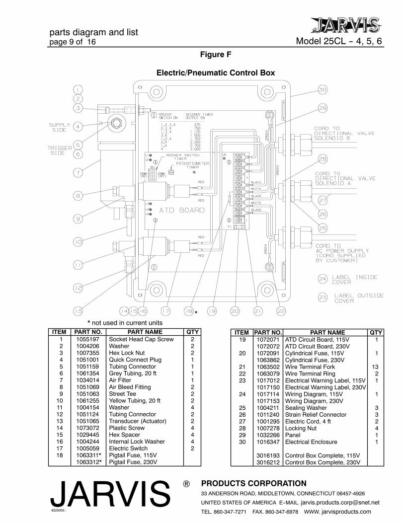
4.3 An air regulator must be installed to the air sup-ply inlet at the quick connect plug (item 4, Fig-ure F).
5 Make all necessary hose connections. Refer to ap-plicable manifold, item 3 or 20, Figure C.
5.1 Attach one end of both yellow hoses (part num-ber 1061255) to the tube fittings (item 1, FigureC) on the 25CL--4,5,6.
5.2 Attach the free ends of the yellow hoses to thefittings (item 12, Figure F) on the anti--tie downelectric/pneumatic control box.
5.3 Attach one end of the grey hose (part number1061354) to the tube fitting (item2, FigureC) onthe 25CL--4,5,6.
5.4 Attach the free end of the grey hose to the fitting(item 5, Figure F) on the anti--tie down electric/pneumatic control box.
6 Make all the necessary wiring connections. All wir-ing must be done in accordance with the national,state and local electrical codes.
Directional Control Valve
Anti--Tie DownElectric / PneumaticControl Box
Figure 1
6.1 Adjust the cutter opening.
6.1.1 Close the cutter.
6.1.2 Release the triggers.
6.1.3 Set the timer [the group of four rocker switcheson the ATD board (item 19 , Figure F)] so thatthe valve on the hydraulic power unit is de--en-ergized after the blades have just fully opened.The older ATD boards have a timer that is asquare potentiometer with a screw driver slot.See Figure 1 above.
operation andmaintenance instructions
Model 25CL -- 4, 5, 6 page 12 of 16
PRODUCTS CORPORATION33 ANDERSON ROAD, MIDDLETOWN, CONNECTICUT 06457-4926
4 Each day, before you begin operation, go throughthe following checklist:
4.1 Make sure that the compressed air supply is atthe proper pressure.
4.2 Make sure that the 25CL--4,5,6 moves freely onthe balancer.
4.3 Make sure that the dual anti-tie down controlhandles (the front and the rear handles) areworking correctly. Depress each trigger sepa-rately and the blades should not close. Depressone trigger, then pause one second and depressthe other trigger and the blades should not close.Repeat this procedure reversing the triggers.
Depress both triggers simultaneously (withinone half second of each other) and the bladesshould close. With the blades closed, releaseone trigger and the blades should open. Contin-ue holding the depressed trigger and then de-press the other trigger. The blades should notclose. Repeat this procedure holding the othertrigger. If the tool malfunctions, remove it fromservice and report the problem to your supervi-sor immediately.
5 Making the cut:
5.1 Place 25CL--4,5,6 cutter around the hock, hornor loin of the carcass.
5.2 Depress both triggers simultaneously to closethe blades.
5.3 Release either or both triggers to open theblades.
MAINTENANCE INSTRUCTIONS
IMPORTANT:ALWAYSDISCONNECTALLHYDRAULICAND
AIR HOSES AND SHUT THE POWEROFF IN ACCORDANCE
WITH OSHA’S LOCKOUT/TAGOUT PROCEDURES (29 CFR
1910.147)WHENINSTALLINGORREMOVINGABLADE. AL-
WAYS DISCONNECT ALL HYDRAULIC AND AIR HOSES
AND SHUT THE POWER OFF IN ACCORDANCE WITH
OSHA’S LOCKOUT/TAGOUT PROCEDURES (29 CFR
1910.147) BEFORE PERFORMING ANY MAINTENANCE OR
REPAIRS.
1 DAILY: Refer to Figure D, page 7 and Figure E,page 8 as applicable.
1.1 The 25CL-4,5,6 is equipped with dual anti-tiedown control handles (the front and the rear han-dles). Check for the correct operation of the dualanti-tie down control handles before each shiftevery day. Depress each trigger separately andthe blades should not close. Depress one trig-ger, then pause one second and depress the othertrigger and the blades should not close. Repeat
this procedure reversing the triggers. Depressboth triggers simultaneously (within one half se-cond of each other) and the blades should close.With the blades closed, release one trigger andthe blades should open. Continue holding thedepressed trigger and then depress the other trig-ger. The blades should not close. Repeat thisprocedure holding the other trigger. If the toolmalfunctions, repair or remove it from serviceimmediately.
1.2 At the end of the shift every day, check the levelof oil in reservoir gage (item 10, Figure D, page7 or item 29, Figure E, page 8) and fill if neces-sary.
6 25CL -- 4, 5, 6 CYLINDERDISASSEMBLY: Referto applicable figures; Figure A, page 4 and FigureB, page 5 as noted.
6.1 Place rod coupling (item 13, Figure A or item17, Figure B) in vise.
6.2 Tighten hex jam nut (item 12, Figure A or item28, figure B) up to rod coupling.
6.3 Unscrew piston rod (item 37, Figure A or item43, Figure B) from rod coupling.
6.3.1 It may be necessary to heat up (300° F maxi-mum) the end of the piston rod and the rod cou-pling because the two items are bonded togeth-er with Loctite. Use heat protective gloves.
6.4 Remove hex jam nut (item 12, Figure A or item28, Figure B).
6.10 Remove piston rod (item 37, Figure A or item43, Figure B).
6.11 Remove seal retaining bushing (item 7, FigureA, or item 33, Figure B).
6.12 Inspect the parts for wear and replace them ifnecessary. (See 25CL -- 4, 5, 6 cylinder assem-bly, step 7, for seal replacement instructions).
7 25CL -- 4, 5, 6 CYLINDER ASSEMBLY: Refer toapplicable figures; Figure A, page 4 and Figure B,page 5 as noted.
7.1 Place new o--ring (item 6, Figure A or item 34,Figure B) on seal retaining bushing (item 7, Fig-
ure A or item 33, Figure B). Use Jarvis 1315White Grease.
7.2 Place new o--rings (item 3, Figure A or item 40,Figure B) on bushing retaining plate (item 4,Figure A, or item 39, Figure B) and on cylinderrear plate (item 40, Figure A or item 46, FigureB).
7.3 Install bushing retaining plate (item 4, Figure Aor item 39, Figure B) onto cylinder housing(item 39, Figure A or item 44, Figure B).
7.4 Push piston rod (item 37, Figure A or item 43,Figure B) through cylinder housing (item 39,Figure A or item 44, Figure B).
7.4.1 Be sure that flats onU--cup seals (item 35, Fig-ure A or item 41, Figure B) face together.
7.4.2 Use Jarvis 1315 White Grease or hydraulicfluid in the inside of cylinder housing (item39,Figure A or item 44, Figure B).
7.4.3 The threaded end of piston rod (item 37, Fig-ure A or item 43, Figure B) should be pushedthrough the seal retaining bushing (item7, Fig-ure A or item 33, Figure B).
7.4.4 Use a blunt screwdriver to help guide in thesealed end of piston rod (item 37, Figure A oritem 43, Figure B).
7.5 Install u--cup seals, back up ring and glandwasher (items 8--10, Figure A or items 30--32,Figure B) over piston rod (item 37, Figure A oritem 43, Figure B).
7.5.1 Cover the threads of the piston rodwith a pieceof paper. Spray the paper with silicon.
7.5.2 Roll one u--cup seal (item 8, Figure A or item30, Figure B) over the piston rod.
7.5.3 Place backup ring (item9, FigureAor item32,Figure B) over the piston rod.
7.5.4 Place gland washer (item 10, Figure A or item31, Figure B) over the piston rod.
7.5.5 Roll remaining u--cup seal (item 8, Figure A oritem 30, Figure B) over the piston rod. The u--cup seals must be placed back--to--back.
maintenance instructionsModel 25CL -- 4, 5, 6page 15 of 16
PRODUCTS CORPORATION33 ANDERSON ROAD, MIDDLETOWN, CONNECTICUT 06457-4926
7.6 In one continuous motion, slide seal retainingplate (item 11, Figure A or item 29, Figure B)onto bushing retaining plate (item 4, FigureA oritem 39, Figure B).
7.7 Place assembly into vise. Do not over--tighten!
7.7.1 Clamp piston rod (item 37, Figure A or item43, Figure B) with soft jaws and rest seal re-taining plate (item 11, Figure A or item 29,Figure B) on top of the vise.
7.8 Lubricate the inside of cylinder housing (item39, Figure A or item 44, Figure B) with Jarvis1315 White Grease.
7.9 Push rear plate (item 40, Figure A or item 46,Figure B) into cylinder housing (item 39, FigureA or item 44, Figure B).
7.10 Place handle bracket (item 41, Figure A or item47, Figure B) onto cylinder housing (item 39,Figure A or item 44, Figure B) and fasten withsocket head cap screws (item 43, Figure A oritem 48, Figure B).
7.11 Remove assembly from the vise and temporarilyfasten seal retaining plate (item 11, Figure A oritem 29, Figure B) to cylinder housing (item 39,Figure A or item 44, Figure B).
7.12 Push piston rod (item 37, Figure A or item 43,Figure B) all the way into the cylinder housing(item 39, Figure A or item 44, Figure B).
7.13 Screwhex jamnut (item12, FigureAor item28,Figure B) as far as possible onto the threadedend of piston rod (item 37, Figure A or item 43,Figure B).
7.14 Screw rod coupling (item 13, Figure A or item17, FigureB) onto the threaded end of piston rod(item 37, Figure A or item 43, Figure B). Sealwith Loctite 271.
7.14.1 25CL--4: Adjust rod coupling so that the cen-ter hole on the rod coupling is 41/4 inches fromthe seal retaining plate (item 11, Figure A).
7.14.2 25CL--5: Adjust rod coupling so that the cen-ter hole on the rod coupling is 41/8 inches fromthe seal retaining plate (item 11, Figure A).
7.14.3 25CL--6: Screw rod coupling onto the pistonas far as it will go.
7.15 Back off hex jam nut (item 12, Figure A or item28, Figure B) until it is tightened to rod coupling(item 13, Figure A or item 17, Figure B).
7.16 Remove temporary fasteners.
8 25CL -- 4, 5 BLADEANDLINKASSEMBLY: Re-fer to Figure A, page 4.
8.1 Lubricate the mating pivot area of the blades(item 24) using Jarvis 1315 White Grease.
8.2 Place blades (item 24) into clevis housing (item14).
8.2.1 Place the flat sides of the blades together.
8.2.2 Line up the large holes in clevis housing withthe large holes in the blades.
8.3 Push clevis bolt (item 32) through the alignedholes.
8.4 Tighten set screw (item 31).
8.5 Tighten hex castle nut (item 30).
8.5.1 Back off the hex castle nut so that the bladescanmove, but also so that there is no play in be-tween the blades.
8.6 Install the cotter pin (item 29).
8.7 Place cylinder housing assembly into vise (sealretaining plate, item 11, should be facing up).Do not over--tighten!
8.8 Place the clevis housing assembly onto the sealretaining plate (item 11).
8.9 Fasten clevis housing assembly to the cylinderhousing assembly with washers (item 34), splitlock washers (item 16) and socket head capscrews (item 33).
8.10 Remove complete assembly from the vise.
8.11 Align the hole in the rod coupling (item 13)withthe hole in the clevis housing (item 14).
8.11.1 If all hose couplings are still attached to the25CL -- 4, 5, it will be necessary to relieve thepressure in the cylinder housing (item 39)through quick connect plug (item 44).
8.12 Place toggle links (item 20) into the clevis hous-ing (item 14).
8.12.1 Place the flat side of each toggle link together.
8.12.2 Align the small holes in clevis housing withthe hole of each toggle link.
8.13 Push dowel pin (item 18) into the aligned holes.
8.14 Install link bolts (item 21) and fasten with hexlock nuts (item 19).
8.14.1 Align the small hole in each blade (item 24)with the holes of each toggle link.
8.14.2 Push clevis bolt through and fasten with hexlock nut.
8.14.3 Back off the hex lock nuts so that the bladescan move, but also so that there is no play be-tween the blades.
9 25CL -- 6 BLADE AND LINK ASSEMBLY: Referto Figure B, page 5.
9.1 Lubricate the pivot area of the blades (item 24)using Jarvis 1315 White Grease.
9.2 Place blades (item 24) into clevis housing (item18).
9.2.1 Place the flat sides of the blades together.
9.2.2 Align the large holes in clevis housingwith thelarge holes in the blades.
9.3 Place disc spring (item 26) into wear plate (item25).
9.4 Slide wear plate (item 25) into clevis housing(item 18).
9.4.1 Place the wear plate on top of the blades andalign the holes. The flat side of the wear platecontacts the blade.
9.5 Push blade pivot shaft (item 1) through thealigned holes.
9.5.1 Be sure that the roll pin in the blade pivot shaftis seated in wear plate (item 25).
9.6 Fasten blade pivot shaft (item 1) with washer(item 22) and hex lock nut (item 21).
9.6.1 Back off the hex lock nut so that the blades canmove, but also so that there is no play betweenthe blades.
9.7 Place cylinder housing assembly into vise (sealretaining plate, item 29, should be facing up).Do not over--tighten!
9.8 Place the clevis housing assembly onto the sealretaining plate (item 29).
9.9 Fasten clevis housing assembly to the cylinderhousing assembly with socket head cap screws(item 20).
9.10 Remove complete assembly from the vise.
9.11 Line up the hole in the rod coupling (item 17)with the hole in the clevis housing (item 18).
9.11.1 If all hose couplings are still attached to the25CL -- 6, it will be necessary to relieve thepressure in the cylinder housing (item 44)withquick connect plug (item 50).
9.12 Place toggle links (item 11) into the clevis hous-ing (item 18).
9.12.1 Align the small holes in clevis housing withthe small holes in the toggle links.
9.13 Push dowel pin (item 19) into the aligned holes.
9.14 Install link bolts (item 12) and fasten with hexlock nuts (item 3).
9.14.1 Align the small hole in each blade (item 24)with the hole of each toggle link.
9.14.2 Push link bolt through and fastenwith hex locknut.
9.14.3 Back off the hex lock nuts so that the bladescan move, but also so that there is no play be-tween the blades.
9.15 Install bracket assembly (items 4, 6--8 and 10)and fasten with two (2) button head cap screws(items 2 and 9) and split lock washers (item 5).