Prodigyr ColorMaxr Powder Coating System Customer Product Manual Part 1073883A03 Issued 6/09 NORDSON CORPORATION • AMHERST, OHIO • USA Check http://emanuals.nordson.com/finishing for the latest version. This document is subject to change without notice. For parts and technical support, call the Industrial Coating Systems Customer Support Center at (800) 433-9319 or contact your local Nordson representative.
Transcript
Prodigy� ColorMax�Powder Coating System
Customer Product ManualPart 1073883A03
Issued 6/09
NORDSON CORPORATION • AMHERST, OHIO • USA
Check http://emanuals.nordson.com/finishing for the latest version.This document is subject to change without notice.
For parts and technical support, call the Industrial CoatingSystems Customer Support Center at (800) 433-9319 or
Contact UsNordson Corporation welcomes requests for information, comments, andinquiries about its products. General information about Nordson can befound on the Internet using the following address:http://www.nordson.com.Address all correspondence to:
Nordson CorporationAttn: Customer Service555 Jackson StreetAmherst, OH 44001
NoticeThis is a Nordson Corporation publication which is protected by copyright.Original copyright date 2006. No part of this document may bephotocopied, reproduced, or translated to another language without theprior written consent of Nordson Corporation. The information containedin this publication is subject to change without notice.
Trademarks
Apogee, ColorMax, HDLV, iControl, Prodigy, Nordson, and the Nordsonlogo are registered trademarks of Nordson Corporation.
AeroDeck, AeroWash, and Powder Port are trademarks of NordsonCorporation.
Change Record i
Part 1073883A03� 2009 Nordson Corporation
Change RecordRevision Date Change
A03 6/09 Noted that air dryer interlock not used after April 2009 in Troubleshootingproblems 4 and 5. Added cyclone cleaning procedure using cyclonecleaning media in Maintenance. Added Apogee conditioning procedure inMaintenance. Added notes in Operation about conditioning and usinggloves.
Change Recordii
Part 1073883A03 � 2009 Nordson Corporation
Safety 1-1
Part 1073883A03� 2009 Nordson Corporation
Section 1Safety
Introduction Read and follow these safety instructions. Task- and equipment-specificwarnings, cautions, and instructions are included in equipmentdocumentation where appropriate.
Make sure all equipment documentation, including these instructions, isaccessible to all persons operating or servicing equipment.
Qualified Personnel Equipment owners are responsible for making sure that Nordson equipmentis installed, operated, and serviced by qualified personnel. Qualifiedpersonnel are those employees or contractors who are trained to safelyperform their assigned tasks. They are familiar with all relevant safety rulesand regulations and are physically capable of performing their assignedtasks.
Intended Use Use of Nordson equipment in ways other than those described in thedocumentation supplied with the equipment may result in injury to personsor damage to property.
Some examples of unintended use of equipment include
� using incompatible materials
� making unauthorized modifications
� removing or bypassing safety guards or interlocks
� using incompatible or damaged parts
� using unapproved auxiliary equipment
� operating equipment in excess of maximum ratings
Regulations and Approvals Make sure all equipment is rated and approved for the environment in whichit is used. Any approvals obtained for Nordson equipment will be voided ifinstructions for installation, operation, and service are not followed.
All phases of equipment installation must comply with all federal, state, andlocal codes.
Safety1-2
Part 1073883A03 � 2009 Nordson Corporation
Personal Safety To prevent injury follow these instructions.
� Do not operate or service equipment unless you are qualified.
� Do not operate equipment unless safety guards, doors, or covers areintact and automatic interlocks are operating properly. Do not bypass ordisarm any safety devices.
� Keep clear of moving equipment. Before adjusting or servicing anymoving equipment, shut off the power supply and wait until theequipment comes to a complete stop. Lock out power and secure theequipment to prevent unexpected movement.
� Relieve (bleed off) hydraulic and pneumatic pressure before adjusting orservicing pressurized systems or components. Disconnect, lock out,and tag switches before servicing electrical equipment.
� Obtain and read Material Safety Data Sheets (MSDS) for all materialsused. Follow the manufacturer’s instructions for safe handling and useof materials, and use recommended personal protection devices.
� To prevent injury, be aware of less-obvious dangers in the workplacethat often cannot be completely eliminated, such as hot surfaces, sharpedges, energized electrical circuits, and moving parts that cannot beenclosed or otherwise guarded for practical reasons.
Fire Safety To avoid a fire or explosion, follow these instructions.
� Do not smoke, weld, grind, or use open flames where flammablematerials are being used or stored.
� Provide adequate ventilation to prevent dangerous concentrations ofvolatile materials or vapors. Refer to local codes or your material MSDSfor guidance.
� Do not disconnect live electrical circuits while working with flammablematerials. Shut off power at a disconnect switch first to preventsparking.
� Know where emergency stop buttons, shutoff valves, and fireextinguishers are located. If a fire starts in a spray booth, immediatelyshut off the spray system and exhaust fans.
� Clean, maintain, test, and repair equipment according to the instructionsin your equipment documentation.
� Use only replacement parts that are designed for use with originalequipment. Contact your Nordson representative for parts informationand advice.
Safety 1-3
Part 1073883A03� 2009 Nordson Corporation
Grounding WARNING: Operating faulty electrostatic equipment is hazardous and cancause electrocution, fire, or explosion. Make resistance checks part of yourperiodic maintenance program. If you receive even a slight electrical shockor notice static sparking or arcing, shut down all electrical or electrostaticequipment immediately. Do not restart the equipment until the problem hasbeen identified and corrected.
Grounding inside and around the booth openings must comply with NFPArequirements for Class II, Division 1 or 2 Hazardous Locations. Refer toNFPA 33, NFPA 70 (NEC articles 500, 502, and 516), and NFPA 77, latestconditions.
� All electrically conductive objects in the spray areas shall be electricallyconnected to ground with a resistance of not more than 1 megohm asmeasured with an instrument that applies at least 500 volts to the circuitbeing evaluated.
� Equipment to be grounded includes, but is not limited to, the floor of thespray area, operator platforms, hoppers, photoeye supports, andblow-off nozzles. Personnel working in the spray area must begrounded.
� There is a possible ignition potential from the charged human body.Personnel standing on a painted surface, such as an operator platform,or wearing non-conductive shoes, are not grounded. Personnel mustwear shoes with conductive soles or use a ground strap to maintain aconnection to ground when working with or around electrostaticequipment.
� Operators must maintain skin-to-handle contact between their hand andthe gun handle to prevent shocks while operating manual electrostaticspray guns. If gloves must be worn, cut away the palm or fingers, wearelectrically conductive gloves, or wear a grounding strap connected tothe gun handle or other true earth ground.
� Shut off electrostatic power supplies and ground gun electrodes beforemaking adjustments or cleaning powder spray guns.
� Connect all disconnected equipment, ground cables, and wires afterservicing equipment.
Action in the Event of a Malfunction If a system or any equipment in a system malfunctions, shut off the systemimmediately and perform the following steps:
� Disconnect and lock out electrical power. Close pneumatic shutoffvalves and relieve pressures.
� Identify the reason for the malfunction and correct it before restarting theequipment.
Disposal Dispose of equipment and materials used in operation and servicingaccording to local codes.
Safety1-4
Part 1073883A03 � 2009 Nordson Corporation
Description 2-1
Part 1073883A03� 2009 Nordson Corporation
Section 2Description
IntroductionThis manual covers Colormax powder coating booths used with ProdigyAutomatic Systems. A complete system includes Prodigy Powder Port�feed centers, Prodigy automatic powder spray guns, and Prodigy iControl�integrated control systems. Options include Prodigy manual spray gunsand controllers, and automatic gun positioners, oscillators, or reciprocators.
This manual includes a description of the major system components andtheir operation; daily system operation procedures; and booth maintenance,troubleshooting, and repair procedures and normal wear parts.
Because powder coating systems are customized to meet customerrequirements, your system may have controls and equipment not describedin this manual or located in different positions. Your Nordson representativecan provide you with additional information and training to supplement thismanual.
For information on other system components, refer to the followingmanuals:
Prodigy Powder Port Feed Center: 1056625Lance Assembly: 1084294Prodigy II High-Capacity Pump (Transfer) 1092270Prodigy II Automatic System Pump Panel: 1102110Prodigy III HDLV Pump 1081195Prodigy iControl Console: 1105820iControl Operator Interface: 1056418iControl Operator Card: 1024758Prodigy Automatic Spray Gun: 1054075Prodigy Automatic Gun Clamp: 1054549Prodigy II Manual Spray Gun: 1077434Prodigy III Manual System: 1102106Prodigy II System Troubleshooting: 1081071Color Change Procedures Flip Chart 1066156
NOTE: This manual covers the standard 11250-cfm Colormax powdercoating system. Other cfm sizes can be custom configured, but are notcovered in this manual.
Description2-2
Part 1073883A03 � 2009 Nordson Corporation
System Components
Table 2-1 Systems Components (See Figure 2-1)
Item Component Function
1 After Filter Filters unusable powder from the air before returning the air tothe spray area.
2 Cyclones Reclaim usable powder and return it to the powder feedcenter.
3 Cyclone Inlet Duct Routes oversprayed powder entrained in air flow to thecyclones.
4 Booth Enclosure Contains oversprayed powder while parts are being coated.
5 Manual OperatorOpenings withPlatforms
Allow operators to manually touch up parts either entering orexiting the booth enclosure.
6 Powder Port FeedCenter
Supplies powder to the Prodigy spray guns and recyclesreclaimed powder.
7 Gun Positioners/GunBlow-Off System(Optional)
Blows powder off the spray guns while moving the spray gunsout of the booth enclosure.
NS Roll-On/Roll-Off System(Optional)
Moves the system offline for cleaning, color change, or repair.
Description 2-3
Part 1073883A03� 2009 Nordson Corporation
System Components (contd)
1
24
67
5
3
Figure 2-1 Colormax System Components
Note: Typical Colormax system shown. Equipment and locations may vary.
Description2-4
Part 1073883A03 � 2009 Nordson Corporation
Booth Enclosure
Table 2-2 Booth Enclosure Components
Item Component Description
1 Canopy Contains the oversprayed powder. Air flow through thecanopy openings carries overspray (powder not deposited onthe parts being coated) suspended in the air through theAeroDeck and into the horizontal duct leading to the cyclones.
2 Floor Collects oversprayed powder until it is drawn under theAeroDeck and into the cyclones. The floor’s stainless steelconstruction ensures that the operator is grounded while he orshe is cleaning the booth enclosure.
3 AeroDeck� Evenly distributes the air draw from the cyclones through theenclosure.
4 AeroWash� System Periodically sends pulses of air down the sloped areas of thecanopy walls to reduce powder buildup on the floor.
1
2
3
4
Figure 2-2 Booth Enclosure Components
Note: Half of canopy removed for clarity.
Description 2-5
Part 1073883A03� 2009 Nordson Corporation
Gun Positioners/Gun Blow-Off System (Optional)
Table 2-3 Gun Movers/Gun Blow-Off System Components
Item Component Description
1 Air Manifolds Supply air to the blow-off nozzles.
2 Blow-Off Nozzles Blow off oversprayed powder from the spray guns as the sprayguns are being pulled out of the booth enclosure.
3 In/Out Gun Positioners Move the spray guns into or out of the booth enclosure.
4 Oscillators orReciprocators(Optional)
Move the spray guns in repetitive or programmed patterns forthorough part coverage; position spray guns in betweenblow-off nozzles during color change.
1
2
4
3
Figure 2-3 Gun Movers/Gun Blow-Off Assist System
Description2-6
Part 1073883A03 � 2009 Nordson Corporation
Cyclones and Reclaim System
Table 2-4 Cyclones and Reclaim System
Item Component Description
1 Cyclones Separate the usable powder from the air flow through therecovery system. Twin tapered cylinders, connected to theinlet air ducts, transfer pan, and banjo housing at the topwhich connects to the afterfilter through ductwork.
2 Transfer Pan Collects reclaimed powder and fluidizes it for the HDLVtransfer pump.
3 HDLV Transfer System Transports the fluidized reclaimed powder from the transferpan to the feed center.
1
3
2
Powder Tubing − Deliveryto Feed Center
Fludizing Air
Powder Tubing − Suction
Figure 2-4 Cyclones and HDLV Transfer System
Description 2-7
Part 1073883A03� 2009 Nordson Corporation
Afterfilter
Table 2-5 After Filter Components
Item Component Description
1 Final Filters Remove any remaining fine powder particles from the air beforereturning the air to the spray room.
2 Fan/Motor Assembly Draws powder-laden air out of the booth enclosure; through thecyclones and ductwork; into the afterfilter; and back into the sprayroom.
3 Waste Hoppers Collect powder particles that are blown off the cartridge filters.
4 Fluidizing Plates Fluidize the powder in the waste hoppers, allowing the powder to bepumped out of the waste hoppers.
5 Intake Duct Brings powder-laden air from the cyclones to the after filter.
6 Afterfilter Panel Contains pulse timer panel, PULSE ON DEMAND switch, anddifferential pressure switches and gauges.
Refer to After Filter Panel for more information.
7 Cartridge Filters Filter powder particles out of the air before the air is drawn into thefan section.
8 Pulse Valves Periodically send pulses of air through the cartridge filters to blowoff powder collected on the cartridges.
9 Pulse Air Manifolds Distribute compressed air to the pulse valves.
10 Pulse Valve Solenoids Signal the pulse valves to open based on pulse valve timer settings.
NOTE: The afterfilter may have either deflagration vents or an explosion suppression system. Contactyour Nordson representative for information about the explosion venting or suppression equipment.
2
3
5
6
7
10
9
8
9
1
8
4
Figure 2-5 AfterFilter—Front and Side Views
Description2-8
Part 1073883A03 � 2009 Nordson Corporation
Afterfilter OperationSee Figure 2-5.
Powder is conveyed through the intake duct (5) into the collector section,where powder collects on the external surfaces of the cartridge filters (7).The air passes through the cartridge filters and flows up into the final filtersection, through the fan (2) and final filters (1) back into the spray room.
The pulse valves (8) periodically release large volumes of compressed airinto the centers of the cartridge filters, blowing the accumulated powder offthe filters. Pulsing is controlled by the pulse valve timer in the after filterpanel (6), which allows you to set both the time between pulses (delay) andthe length (duration) of the pulse. The PULSE ON DEMAND switch on theafterfilter panel allows the operator to set cartridge pulsing to be eithercontinuous or on-demand:
� CONTINUOUS: Cartridges are pulsed at operator-specified intervals setat the pulse valve timer.
� ON-DEMAND: Cartridges are pulsed only when the cartridge filterdifferential pressure switch detects a pressure drop across the cartridgefilters of 6.5-in. water column (wc).
The powder falls into the waste hoppers (3) in the bottom of the collectorsection. The waste hoppers are equipped with fluidizing plates (4), whichdiffuse air into the powder so that it will flow easily when the waste hoppersare emptied.
The final filter differential pressure switch monitors the pressure drop acrossthe final filters. At 2.5-in. wc, a red warning light on the system controlpanel lights. At 3-in. wc, the entire system shuts down.
A safety gate in the duct between the booth and the afterfilter is retractedduring normal operation. When the system is shut down the gate is closed.If a fire is detected in the booth, the fire detection system will shut down theexhaust fan and the gate will close to isolate the afterfilter from the booth.
Description 2-9
Part 1073883A03� 2009 Nordson Corporation
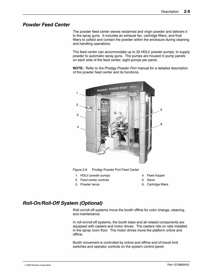
Powder Feed Center The powder feed center sieves reclaimed and virgin powder and delivers itto the spray guns. It includes an exhaust fan, cartridge filters, and finalfilters to collect and contain the powder within the enclosure during cleaningand handling operations.
The feed center can accommodate up to 32 HDLV powder pumps, to supplypowder to automatic spray guns. The pumps are housed in pump panelson each side of the feed center, eight pumps per panel.
NOTE: Refer to the Prodigy Powder Port manual for a detailed descriptionof the powder feed center and its functions.
1
2
3
4
5
6
Figure 2-6 Prodigy Powder Port Feed Center
1. HDLV powder pumps2. Feed center controls3. Powder lance
4. Feed hopper5. Sieve6. Cartridge filters
Roll-On/Roll-Off System (Optional)Roll-on/roll-off systems move the booth offline for color change, cleaning,and maintenance.
In roll-on/roll-off systems, the booth base and all related components areequipped with casters and motor drives. The casters ride on rails installedin the spray room floor. The motor drives move the platform online andoffline.
Booth movement is controlled by online and offline end-of-travel limitswitches and operator controls on the system control panel.
Description2-10
Part 1073883A03 � 2009 Nordson Corporation
Control PanelsRefer to the following tables for a description of typical system controls.The contents and locations of the control panels vary depending on thesystem configuration and options installed.
Powder Feed Center Control PanelFor more information on the feed center controls and operation, refer to thefeed center manual 1056625.
Control Description
Emergency Stop Shuts down the entire powder coating system. Rotate the button in thedirection of the arrow to reset.
Reclaim TransferOn/Off
Turns on and off the reclaim transfer pump. The pump runs continuouslywhen turned on. Lights amber when on.
Virgin Transfer On/Off Enables and disables the virgin transfer pump. When enabled, the pump iscontrolled by the level sensor and a delay timer. The delay timer prevents thepump from starting until the delay runs out, to prevent pump chattering (rapidon/off cycles). Lights amber when on.
Color Change Start Starts the color change process. The spray guns, pumps, and lances areautomatically purged. Lights green when on.
Color Change Stop Used by the feed center operator to notify the system that all feed center colorchange tasks are complete. Stops process if pressed before complete.
Reclaim/Virgin TransferPurge Start
Starts the reclaim and virgin transfer pump purge process. Lights green whenon, flashes during purge cycle.
Reclaim/Virgin TransferPurge Stop
Stops the reclaim and virgin transfer pump purge process.
Sieve On/Off Starts and stops the vibratory sieve.
Description 2-11
Part 1073883A03� 2009 Nordson Corporation
System Control PanelStandard Controls Description
Disconnect Switch Turns on and off system power and power to the powder feed center controlpanel.
System Start Pushbutton/Green Indicator. Turns on power to the system control panel, if allinterlocks (fire detection system, explosion suppression system) and limitswitches are closed.
System Stop Turns off power to the system control panel.
System Ready Green Indicator. Lights when the SYSTEM START button is pressed and theduct safety gate is fully open.
Afterfilter Fan Start Pushbutton/Amber Indicator. Turns on afterfilter exhaust fan.
Afterfilter Fan Stop Turns off afterfilter fan. Spray guns are interlocked with the fan, if the fan isshut off the spray guns shut off.
Final Filter Warning Red Indicator. Lights if the final filter differential pressure exceeds 2.5 in. wc.If the pressure exceeds 3 in. wc the system will be shut down.
AeroWash SelectorSwitch
3-Position Switch, Off/On/Timed − Use to control AeroWash functions. Selectcontinuous on, timed on, or off.
Feed Center Fan Start Pushbutton/Amber Indicator. Turns on feed center exhaust fan.
Feed Center Fan Stop Turns off feed center exhaust fan.
Optional Controls Description
Booth Lights Switch Turns on and off booth lights (customer installed).
Oscillator #1, 2 Start Pushbutton/Amber Indicator. Turns on oscillators.
Cyclone Disconnect 2-Position Switch, Open/Close. Open to move booth, close after move. Opendisconnects duct work from cyclone.
Duct Dampers 2-Position Switch, Online/Offline. Routes airflow through ductwork. Selectonline when booth in production position; offline when booth moved offline.
Afterfilter Panel Control Description
Pulse On DemandSwitch
CONTINUOUS: Cartridges are pulsed at operator-specified intervals set at the pulse valve timer.
ON-DEMAND: Cartridges are pulsed continuously, but only when the cartridge filter differential pressure switch detects a pressure drop across the cartridge filters of 6.5-in. wc.
Differential PressureGauges and Switches
Detect the pressure drop across the cartridge and final filters to indicatedegree of clogging of the filter media. The final filter differential pressureswitch is set to light a red warning light at 2.5-in. wc and shut down the entiresystem at 3-in. wc.
Pulse Valve Timer (Inside Panel) Use to set the duration (on time) and delay (off time) ofcontinuous cartridge pulsing.
Description2-12
Part 1073883A03 � 2009 Nordson Corporation
Typical System OptionsRefer to the manuals shipped with optional equipment for more information,or contact your Nordson Corporation representative.
Equipment Description
Air Dryer Removes moisture from the system air supply. Most systems useregenerative-desiccant or refrigerated air dryers.
Gun Positioners Move the spray guns horizontally or vertically toward or away from theworkpieces.
Oscillators Move the spray guns in simple repetitive strokes.
Reciprocators Move the spray guns in programmed patterns.
Powder DrumUnloaders
Transfer powder from shipping drums to the powder feed center.
Fluidizing Hoppers Plastic boxes with a compartment and porous fluidizing plate in the bottom.Low pressure compressed air passing through the plate fluidizes the powder.
Prodigy iControl PartIdentification and SprayGun Triggering System
Identifies and tracks parts on the conveyor and controls gun triggering, powderflow, and electrostatic voltage. Controls movement of gun positioners andreciprocators.
Prodigy Manual SprayGuns and Controllers
Used along with automatic spray guns for final touch-up and coating ofhard-to-reach locations.
Operation 3-1
Part 1073883A03� 2009 Nordson Corporation
Section 3Operation
WARNING: Allow only qualified personnel to perform the following tasks.Follow the safety instructions in this document and all other relateddocumentation.
IntroductionThe programmable relays in the powder feed center and system controlpanels control the automatic processes for the booth and feed center. Therelays are typically programmed by your Nordson application engineer tosuit your application requirements.
NEW SYSTEMS: Before starting up your powder coating system for the firsttime, perform the Initial Canopy Conditioning procedure in Maintenance.The inside surfaces of the canopy must be clean, free of oils, and dry. Aclean canopy prevents powder from sticking, and allows for fast colorchanges.
Typical Operating SettingsThe settings listed here are approximate. You may need to adjust thesesettings to obtain the desired results.
Operating Air PressuresAir Pressure Setting
Input (System) 6 bar (90 psi)
Cartridge Filter Pulse (Afterfilter) 4 bar (60 psi)
Waste Hopper Fluidizing (Afterfilter) 1 bar (15 psi)
AeroWash 5.5 bar (80 psi)
Operation3-2
Part 1073883A03 � 2009 Nordson Corporation
Afterfilter Cartridge Filter Pulsing The cartridge filters in the afterfilter housing are pulsed with compressed airto knock off accumulated powder and maintain air flow through the booth.The pulse delay and duration are controlled by the timer board inside theafterfilter control panel. Pulsing starts when the exhaust fan is turned onand stops when it is turned off.
Timer Setting
On Time (Duration) 0.07 seconds
Off Time (Delay) 90 seconds
System Controls Setup The following describes the booth and feed center functions and settingscontrolled by the programmable relay in the system control panel, and thesteps required to set the values in the relay.
AeroWash Operation The AeroWash system consists of compressed air jets that clean powderfrom the sloping surfaces of the spray booth interior and the AeroDeckpanels. Typically, three pilot-activated air valves control the flow of air to theleft and right sides of the booth and the AeroDeck panels.
The AeroWash system operation is controlled by the selector switch on thespray system control panel. The switch positions are OFF, ON, and TIMED.
Timed Operation When TIMED is selected, the air valves are opened sequentially to movepowder off the surfaces and into the collection system.
The timed sequence is controlled by a delay and duration cycle. The delayvalue (B01:T) is the amount of time between a duration cycle. When thedelay timer runs out, the duration cycle starts, during which each valve isopened for the duration value (B02:T), one after the other. When theduration cycle is completed the delay timer is restarted.
On Operation When ON is selected, all three air valves are opened at the same time andstay open until another mode of operation is selected or the switch selectionis overridden.
Operation 3-3
Part 1073883A03� 2009 Nordson Corporation
Selection Switch Overrides The color change cycle overrides the AeroWash switch selection. When theColor Change Start button is pressed the valves are closed. Once the gunsare fully retracted from the booth, the valves are opened continuously toassist in the cleaning of the booth. When the Color Change Stop button ispressed the valves resume normal timed operation.
The AeroWash system is interlocked with the spray booth exhaust fan (inthe afterfilter) so if the fan is turned off the AeroWash system is also turnedoff.
Feed Center Cartridge Filter Pulse Operation The feed center cartridge filters collect the waste powder contained insidethe feed center. The filters must be cleaned periodically to remove theaccumulated powder and maintain the air flow through the feed center.
The filters are cleaned by directing pulses of compressed air into the interiorof the filters, which knocks the powder off the external surfaces of the filters.The powder falls into the waste hopper under the filters, where it is held untilthe operator pumps it into a waste container.
Filter pulsing is controlled by a selector switch on the feed center solenoidpanel. The switch allows pulsing to be set to OFF, CONT (continuous), orTIMED operation.
Continuous Pulsing If CONT is selected, each filter pulse valve is turned on for a short duration(B08:T) followed by a delay (B06:T), then the next filter is pulsed. Thissequence is repeated continuously.
Timed Pulsing If TIMED is selected, a pulse cycle delay (B05:T) separates each pulsecycle. When the cycle delay timer runs out, the pulse cycle starts. Duringthe pulse cycle, each filter is pulsed in turn, using the B08:T and B06:Tdelay and duration timers. When the pulse cycle is completed the cycledelay timer is restarted. This sequence is repeated continuously.
Selection Switch Overrides Filter pulsing is disabled during a color change cycle. Filter pulsing isinterlocked with the feed center exhaust fan so if the fan is turned off thenpulsing is also turned off.
Operation3-4
Part 1073883A03 � 2009 Nordson Corporation
Feed Center Waste Powder Transfer Operation The powder collected in the feed center waste hopper is transferred by aventuri-type transfer pump to a waste container. The transfer pump iscontrolled by START and STOP buttons on the feed center. When theSTART button is pressed, an off delay timer timer (B10:T) starts. The pumpstops when the STOP button is pressed, or is automatically turned off whenthe off delay timer runs out.
Switch Selection Overrides The transfer pump control is interlocked with the feed center exhaust fan.The transfer pump will not start if the feed center fan is not running.
Oscillator/Reciprocator Operation If reciprocators are used, then starting a color change causes thereciprocators to move to the Park position for external blowoff.
If oscillators are used, starting a color change causes the oscillators tomove to the bottom-of-stroke position so that the spray guns are in thecorrect vertical location for the external gun blowoff cycle. The sequence ofevents is as follows:
1. Color change signal is received.
2. Bottom-of-stroke sensor detects oscillator crank arm and starts delay(B11:T, B12:T). While delay timer is running the sensor signal isignored.
3. Oscillator slows to 20% speed.
4. Bottom-of-stroke sensor detects oscillator crank arm on next revolutionand stops oscillator.
5. External blowoff starts.
Bottom-of-stroke sensor must detect crank arm at all times during colorchange cycle.
When the color change STOP button is pressed, the reciprocators oroscillators are released from Park or bottom-of-stroke and resume normaloperation.
Programmable Relay Setup
Changing Function Values Open the system control panel door to access the programmable relay.
NOTE: These instructions are also reproduced on a label on the inside ofthe control panel door.
Operation 3-5
Part 1073883A03� 2009 Nordson Corporation
Figure 3-7 System Control Panel Programmable Relay
1. Press the ESC and OK keys simultaneously.
2. Press the DOWN (�) key until the display pointer is on SET PARAM.
3. Press the OK key. The display shows B0x:T and register preset value.
4. Press the UP (�) key or DOWN (�) key to select the register presetvalue to change.
5. Press the OK key. The display highlights the first digit of the presetvalue.
6. Press the LEFT (�) or RIGHT () key to highlight the digit to change.
7. Press the UP (�) key or DOWN (�) key to change the digit value.
8. After each digit is changed to the desired value, press the OK key.
9. To change another value, go back to step 4. To exit, press the ESC keytwice to return to the RUN display.
Function Settings
Parameter Description Setting
B01:T AeroWash Output Cycle Delay (minutes) 5.00
B02:T AeroWash Output #1 Duration (seconds) 5.00
B03:T AeroWash Output #2 Duration (seconds) 5.00
B04:T AeroWash Output #3 Duration (seconds) 5.00
B05:T Feed Center Filter Pulse Cycle Delay(minutes)
10.00
B06:T Feed Center Filter Pulse Off Duration(seconds)
15.00
B08:T Feed Center Filter Pulse On Duration(seconds)
00.10
B010:T Feed Center Waste Powder Off Delay(minutes)
StartupUse the following procedure to start up the system on a daily basis.
NOTE: These procedures assume that the system was cleaned before itwas shut down.
1. Make sure the disconnect switches on the system and afterfilter panelare turned on.
2. If applicable, move the system to the online position. Refer to BoothMoving in this section for more information.
3. Press the SYSTEM START button on the system control panel. TheSYSTEM START indicator will light.
The slide gate in the ductwork between the cyclones and the afterfilteropens. When the gate is fully open, the SYSTEM READY indicatorlights and the system is ready to start.
4. Press the AFTERFILTER FAN START button to start the afterfilterexhaust fan.
5. Press the FEED CENTER FAN START button to start the feed centerexhaust fan.
6. Prepare the bulk feed system (if used) for operation.
7. Prepare the feed center for operation. Refer to the Prodigy Powder Portfeed center manual 1056625.
8. If used, press the OSCILLATOR #1 and #2 START buttons. Adjust theoscillator speed with the OSCILLATOR #1 and #2 SPEED dials ifnecessary.
9. Turn the AEROWASH switch to the TIMED position.
The booth is now ready for production. For spray gun operation, refer to thefollowing manuals:
NOTE: It is important that the inside surface of the canopy is not touchedby bare hands. Skin oils and other contaminants will affect the ability of thecanopy to shed powder during blowoff. Operators should wear cottongloves when working with the canopy.
Operation 3-7
Part 1073883A03� 2009 Nordson Corporation
Booth Moving (Optional)This procedure only applies to Roll On/Roll Off booths.
1. Move the CYCLONE DISCONNECT switch to the OPEN position. Thecyclones disconnect from the afterfilter inlet duct. A limit switch preventsmovement until the cyclones are fully disconnected.
2. Press the BOOTH MOVER ENABLE button. The booth mover buzzersounds and the booth mover pendant button is enabled for threeminutes.
3. Visually check the area around the booth for obstructions. Clear thearea of all obstructions and personnel.
4. Press and hold the pendant button to move the booth to the desiredposition. The booth stops moving when either you release the button orthe booth reaches either the online or offline position.
5. When the booth is in the online or offline position, move the CYCLONEDISCONNECT switch to the CLOSED position. The cyclones connectto the after filter inlet duct.
6. Move the DUCT DAMPERS switch to the ONLINE or OFFLINE position.
Color Changing A color change sequence is started by pressing the Color Change STARTbutton on the Prodigy feed center control panel. The sequence is finishedor aborted by pressing the Color Change STOP button.
Refer to the Prodigy Powder Port feed center manual for detailed colorchange procedures. The following procedure describes the color changeprocedure and lists the booth cleaning steps.
Pressing the Start button starts the spray gun purge and blowoff cycles.AeroWash air is turned off, and feed center cartridge filter pulsing is shut off.
The gun movers move the guns to the blowoff position, then move all theway in. The guns are purged and blown off while they are moved out of thebooth.
When the spray gun purge and blowoff cycles are complete the AeroWashair is turned on continuously to assist in the manual cleaning of the booth.
Operation3-8
Part 1073883A03 � 2009 Nordson Corporation
Color Changing (contd)
Once the guns are retracted, you can start cleaning the booth:
NOTE: It is important that the inside surface of the canopy is not touchedby bare hands. Skin oils and other contaminants will affect the ability of thecanopy to shed powder during blowoff. Operators should wear cottongloves when working with the canopy.
1. At the entrance end of the booth, blow off the door sills, then close theentrance doors.
2. Blow off the exit door sills, then enter the booth and blow off the ceiling,walls, and floor, working towards the entrance end.
3. One at a time, blow off the tops of the AeroDeck panels, then flip themup and blow off the undersides.
4. Blow off the extraction duct door, then open it and blow out theextraction duct.
5. Set the AeroDeck panels back into operating position and exit the booth.
Follow the rest of the color change steps in the Prodigy Powder Port feedcenter manual 1056625.
NOTE: Whenever it becomes difficult to blow powder off the canopysurface, perform the Booth Canopy Conditioning procedure on page 4-4.Conditioning keeps the canopy easy to clean and reduces the potential forcontamination of reclaimed powder.
Shutdown Use the following procedure to shut down the system.
1. Move the booth offline, if desired.
2. Clean the system by performing the color change process, but do notinstall a new powder source.
3. Press the SYSTEM STOP button on the system control panel. This willshut down all system motors and close all solenoid valves.
4. If you will be shutting down the system for maintenance, repair, or anextended period of time, turn the disconnect switches on the system andexhauster (if applicable) control panels to the off position.
Maintenance 4-1
Part 1073883A03� 2009 Nordson Corporation
Section 4Maintenance
WARNING: Allow only qualified personnel to perform the following tasks.Follow the safety instructions in this document and all other relateddocumentation.
Initial Canopy Conditioning Perform this procedure on new canopies before initial startup. Thisprocedure removes oils or other contaminants from the canopy, making thecanopy easy to clean and reducing the potential for contamination ofreclaimed powder.
NOTE: Rags used for cleaning must be washed before use to removesizing and starches which would be transferred to the canopy surfaces,degrading the ability of the canopy to shed powder.
1. Wipe down entire canopy with acetone or isopropyl alcohol andpre-washed, 100% cotton rags.
2. Fill two clean buckets with water.
3. Put 2−3 drops of mild dish washing detergent into one of the buckets.This will be the soap bucket.
4. Soak and wring out a hand sponge or a sponge mop in the soap bucket.Wipe down the entire inside of the canopy, frequently wringing out thesponge in the rinse bucket and then re-soaping the sponge in the soapbucket. A continuous wet surface is not necessary, so do not beconcerned if some surfaces air-dry prior to next step. You must makesure that the soap solution contacts all surfaces.
5. Empty the buckets, rinse them, and repeat steps 1−3, for a total of twowash cycles.
6. Empty the buckets and rinse them thoroughly. Fill the buckets withclean water and rinse the entire inside of the canopy, frequently wringingout the sponge in the rinse buckets.
7. Repeat step 5 two more times, for a total of three rinse cycles, thenallow canopy to completely dry before resuming spray operations.
NOTE: It is important that the inside surface of the canopy is not touchedby bare hands. Skin oils and other contaminants will affect the ability of thecanopy to shed powder during blowoff. Operators should wear cottongloves when working with the canopy.
Maintenance4-2
Part 1073883A03 � 2009 Nordson Corporation
Daily MaintenancePerform these procedures daily to keep your system clean and functioningproperly.
System Cleaning
WARNING: Wear an approved respirator and safety glasses or goggleswhen performing maintenance or cleaning operations. Obtain and readMaterial Safety Data Sheets for each powder used.
1. Perform a color change, but do not load a new color powder into thefeed center.
2. Clean the spray guns according to the instructions in their manuals.
WARNING: Use only non-conductive tools to clean the booth interior. Donot use any tools that could create friction sparks. A hot spark could bepulled into the recovery system and ignite an explosion or fire.
3. Remove any powder residue from the booth interior with an air-poweredvacuum and a soft brush attachment. Wipe down all surfaces with adamp, lint-free cloth (do not use tack cloths).
4. Clean the floor around the booth.
5. Check all equipment grounds, hoses, and cables for loose connections,wear, or breakage. Repair or replace as necessary.
Maintenance 4-3
Part 1073883A03� 2009 Nordson Corporation
Daily Equipment Maintenance
Equipment Procedure
Flame DetectorSystem
Check the detector heads every four hours and clean the lenses, if necessary.Make sure air is being supplied to the heads. Make sure the detector systemis operating properly.
Air Dryers Perform any required maintenance as described in your air dryer manual.
Air Velocity Measure the air velocity at all booth openings with a velometer. Minimumvelocity is 36 m/min (120 fpm).
Compressed AirSupply
Hold a clean, white cloth under the supply line drop leg and open the drop-legdrain valve. Water, oil, or other contaminants will stain the cloth. Eliminateany source of contamination. Drain the filters and separators and check thefilter elements. Check all air pressure regulator settings.
NOTE: The air dryer should remain on at all times to prevent moisture fromaccumulating in the compressed air system.
Afterfilter CartridgeFilters and Housings
The cartridge filter differential pressure gauge should read 4−6 in. wc. with theexhaust fan operating. If it is high, check the pulse valve timing. The cartridgefilters should be pulsed often enough to prevent clogging.
Final Filter Housingand Fan
The final filter differential pressure gauge should read 1−2.5-in. wc. with theexhaust fan operating. At 3 in. w.c. the system will shut down.
Oscillators and In/OutGun Positioners
Each shift, make sure the oscillators and in/out gun positioners are movingsmoothly and at the proper speed. Make repairs and adjustments ifnecessary. Follow the lubrication instructions in the equipment manuals.
Powder Spray Guns Clean the spray guns according to the instructions in their manuals.
Prodigy PowderPumps
Visually inspect the pump pinch valves (visible through the transparent pumpbodies). If powder is visible inside the pinch valve cavities, the pinch valve isleaking. Disassemble and replace all pinch valves at the same time. Refer tothe pump manual for instructions and pinch valve kit part number.
Prodigy HDLVTransfer Pumps(Reclaim and VirginPowder)
Visually inspect the pump pinch valves (visible through the transparent pumpbody). If powder is visible inside the pinch valve cavities, the pinch valve isleaking. Disassemble and replace all pinch valves at the same time. Refer tothe pump manual for instructions and pinch valve kit part number.
Sieve Remove and clean the screen. Replace the screen if it is damaged.
Check the rubber seals. Replace any damaged or worn parts.
Workpiece andConveyor Grounds
WARNING: An ungrounded or poorly grounded workpiece,hanger, or conveyor can cause electrical arcing. If arcing isobserved, shut down the system immediately. Correct the causebefore resuming operations. Failure to observe this warningcould result in a fire or explosion, causing property damage andpossible personal injury or death.
Make sure all workpieces are grounded through the hangers and conveyor.The resistance between the workpieces and the hangers, and the hangers andground, must be less than 1 megohm. Use a megohm meter to checkresistances. You will get better transfer efficiency and workpiece coverage at500 ohms or less. Clean the hangers regularly.
Maintenance4-4
Part 1073883A03 � 2009 Nordson Corporation
Weekly Maintenance
Weekly Equipment Maintenance
Equipment Procedure
Booth Enclosure Perform the Booth Canopy Conditioning procedure in this section. Clean thebooth exterior, all attached equipment, and the spray room.
Check the enclosure for cracks, damage, and dirt. Seal any cracks.
Afterfilter DifferentialPressure Gauges
Observe and record the differential pressure gauge readings.
The cartridge filters are clogged if the pressure drop across the filters exceeds6.5-in. wc. The system is programmed so that at 2.5-in. wc, the final filterwarning light on the control panel lights. At 3-in. wc the system shuts down.
Powder Spray Gunsand Cables
Clean the spray guns. Perform electrostatic resistance checks as described inthe spray gun manuals.
HDLV Powder Pumpsand Tubing (Gun andTransfer)
Purge the pumps. If powder is visible inside the pinch valve cavities, the pinchvalve is leaking. Disassemble and replace all pinch valves at the same time.Refer to the pump manual for instructions and kit part numbers.
Check the suction and delivery tubing for blockages or wear. Clear or replacetubing as necessary.
Booth Canopy ConditioningPerform this procedure every six months or whenever it becomes difficult toblow powder off the canopy surface. Conditioning keeps the canopy easy toclean and reduces the potential for contamination of reclaimed powder.
NOTE: To remove impact-fused powder, perform the initial canopyconditioning procedure on page 4-1.
1. Fill two clean buckets with water.
2. Put 2−3 drops of mild dish washing detergent into one of the buckets.This will be the soap bucket.
3. Soak and wring out a hand sponge or sponge mop in the soap bucket.Clean the entire inside of the canopy, frequently wringing out the spongein the rinse bucket and then re-soaping the sponge in the soap bucket.
4. Empty the buckets, rinse them, and repeat steps 1−3, for a total of twowash cycles.
5. Empty the buckets and rinse them. Fill the buckets with clean water andrinse the entire inside of the canopy, frequently wringing out the spongein the rinse buckets.
6. Repeat step 5 two more times, for a total of three rinse cycles. Allow thecanopy to completely dry before resuming spray operations.
NOTE: It is important that the inside surface of the canopy is not touchedby bare hands. Skin oils and other contaminants will affect the ability of thecanopy to shed powder during blowoff. Operators should wear cottongloves when working with the canopy.
Maintenance 4-5
Part 1073883A03� 2009 Nordson Corporation
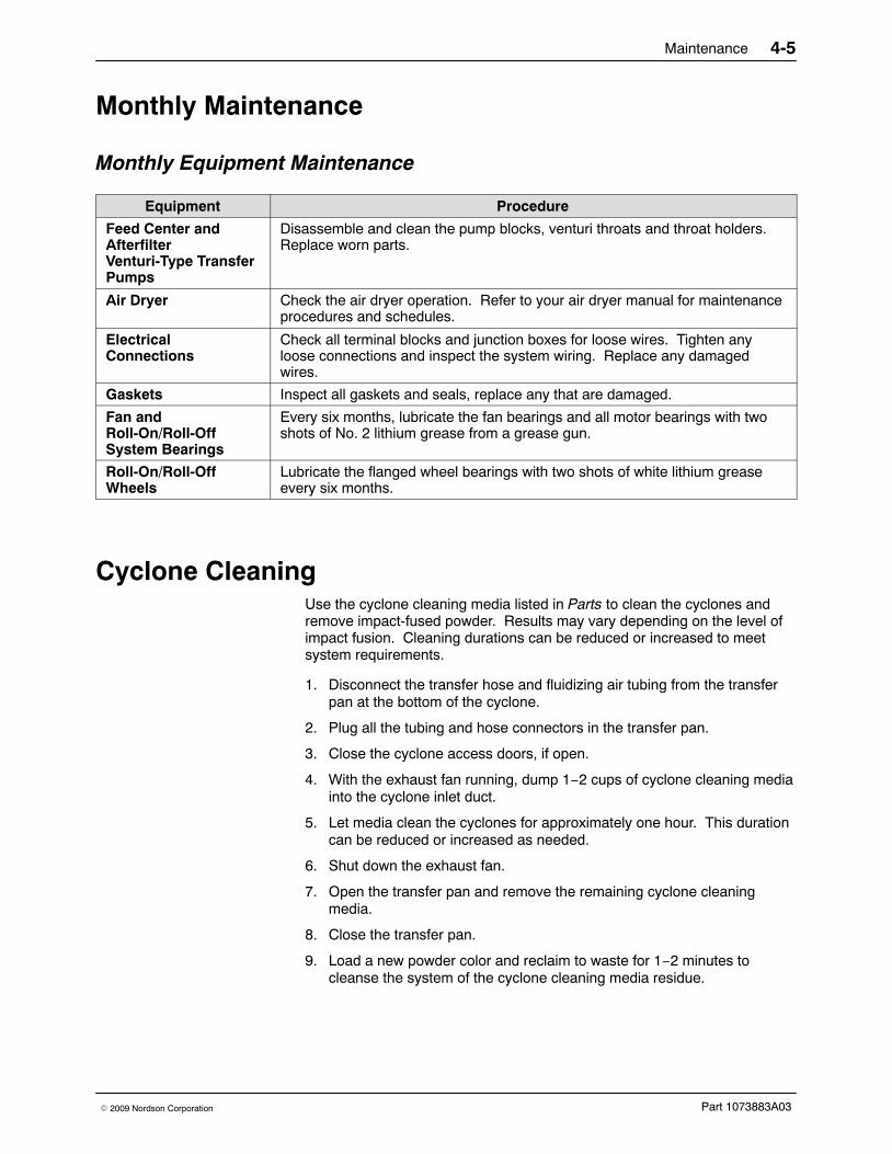
Monthly Maintenance
Monthly Equipment Maintenance
Equipment Procedure
Feed Center andAfterfilterVenturi-Type TransferPumps
Disassemble and clean the pump blocks, venturi throats and throat holders.Replace worn parts.
Air Dryer Check the air dryer operation. Refer to your air dryer manual for maintenanceprocedures and schedules.
ElectricalConnections
Check all terminal blocks and junction boxes for loose wires. Tighten anyloose connections and inspect the system wiring. Replace any damagedwires.
Gaskets Inspect all gaskets and seals, replace any that are damaged.
Fan andRoll-On/Roll-OffSystem Bearings
Every six months, lubricate the fan bearings and all motor bearings with twoshots of No. 2 lithium grease from a grease gun.
Roll-On/Roll-OffWheels
Lubricate the flanged wheel bearings with two shots of white lithium greaseevery six months.
Cyclone Cleaning Use the cyclone cleaning media listed in Parts to clean the cyclones andremove impact-fused powder. Results may vary depending on the level ofimpact fusion. Cleaning durations can be reduced or increased to meetsystem requirements.
1. Disconnect the transfer hose and fluidizing air tubing from the transferpan at the bottom of the cyclone.
2. Plug all the tubing and hose connectors in the transfer pan.
3. Close the cyclone access doors, if open.
4. With the exhaust fan running, dump 1−2 cups of cyclone cleaning mediainto the cyclone inlet duct.
5. Let media clean the cyclones for approximately one hour. This durationcan be reduced or increased as needed.
6. Shut down the exhaust fan.
7. Open the transfer pan and remove the remaining cyclone cleaningmedia.
8. Close the transfer pan.
9. Load a new powder color and reclaim to waste for 1−2 minutes tocleanse the system of the cyclone cleaning media residue.
Maintenance4-6
Part 1073883A03 � 2009 Nordson Corporation
Emptying the Afterfilter Waste HoppersWaste powder transfer is a continuous operation controlled by two solenoidvalves and a timer, located in the afterfilter panel.
When the afterfilter exhaust fan is on the timer (TDR220) is enabled and thewaste powder pump solenoid (SOL 219) is turned on for continuousoperation. The fluidizing and vibrator motor solenoid (SOL 220) is turned onand off by the timer.
Adjustment T1 on the timer sets the amount of time that the fluidizing andvibrator motor solenoid (SOL 220) is turned on. T1 is adjustable for 1−100seconds.
Adjustment T2 on the timer sets the delay between cycles of SOL 220. T2is adjustable for 1−100 minutes.
NOTE: The feed center also has a waste hopper that must be emptied asneeded. Refer to the feed center manual for the procedure.
Initial Setup and Operation See Figure 4-1.
1. Secure the waste lid (8) to an empty 55-gallon drum (5).
2. Connect the ground clamp (4) to a true earth ground.
3. Attach 3/4-in. transfer hoses (9) between the transfer pumps (3) and thehose connectors (6) on the waste lid. Use hose clamps on both ends ofthe transfer hoses.
NOTE: Make sure that all unused hose connectors on the waste lid areplugged.
4. Attach the vent hose (2) to the waste lid vent stub (7). Attach the otherend of the vent hose to the afterfilter vent stub (1).
5. Open the ball valves on the afterfilter air drop to supply compressed airto the transfer pumps and fluidizing/vibrator air pilot valves. The air pilotvalves are controlled by the solenoid valves SOL 219 and 220 in theafterfilter panel.
NOTE: The normal operating air pressure for the transfer pump is 2 bar(30 psi). Increase the transfer pump air pressure if desired. Regulatorsare located on the afterfilter air drop.
Changing Waste Containers 1. Close the air drop ball valves supplying compressed air to the transfer
pumps.
2. Remove the waste lid (8), with hoses attached, from the wastecontainer (5).
3. Install the waste lid on an empty waste container.
4. Open the air drop ball valves.
Maintenance 4-7
Part 1073883A03� 2009 Nordson Corporation
1
32
8
9
94
57
6
3
Figure 4-1 Emptying the Waste Hoppers
1. After filter vent stub2. Vent hose3. Transfer pumps
7. Lid vent stub8. Waste lid9. 3/4-in. Transfer hoses
Maintenance4-8
Part 1073883A03 � 2009 Nordson Corporation
Maintenance Check ListActivity Color
ChangeEachShift Daily Weekly Monthly Every Six
Months
Cleaning
Fire detector head lenses*
Booth enclosure
Final filter compartment
Powder tubing (spray gun and transfer)
Pumps (purge)
Spray guns (purge)
Sieve
Feed center transfer pumps
Canopy Conditioning**
Resistance Checks—SprayGuns
Visual Checks
HDLV pump (gun, transfer) pinch valves
Air supply drop leg
Air dryer drain
Cartridge filter differential pressure gauge
Electrical connections
Final filter differential pressure gauge
Fire detector sensors
Gaskets
Oscillators and in/out gun positioners
Workpiece clearance***
Workpiece grounding
Powder supply levels
Afterfilter waste hoppers****
* Clean fire detector head lenses every 4 hours.
** Or as required.
*** Continuously monitor workpiece clearance.
**** Frequency varies depending on application. Check more frequently if spraying to waste often.
Lubrication Every 6months
Roll-on/roll-off wheel bearings
Fan and motor bearings
Troubleshooting 5-1
Part 1073883A03� 2009 Nordson Corporation
Section 5Troubleshooting
WARNING: Allow only qualified personnel to perform the following tasks.Follow the safety instructions in this document and all other relateddocumentation.
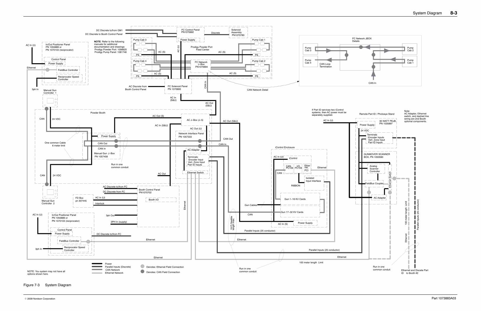
Introduction This section contains troubleshooting procedures for the ColorMax boothonly. Extensive troubleshooting procedures for the feed center, iControlsystem, gun positioners, reciprocators, spray guns, and other systemcomponents can be found in the following manuals and in others not listedhere:
Nordson equipment manuals can be viewed or downloaded from theinternet at http://emanuals.nordson.com/finishing.
If you cannot solve the problem with the information given in these manuals,call the Nordson Finishing Customer Support Center at (800) 433-9319 orcontact your local Nordson representative for help.
Poor workpiece grounding Resistance from the workpiece to theground must be less than 1 megohm.For best results, resistance shouldnot be more than 500 ohms. Cleanthe workpiece hangers, fixtures, andhooks if necessary. Check theconveyor ground.
Spray gun placement incorrect Position the spray guns 254−355 mm(10−14 in.) from the workpieces.Stagger the spray guns 304 mm(12 in.) apart vertically and 381 mm(15 in.) apart horizontally to avoid fanpattern and electrostatic field overlap.Contact your Nordson representativefor advice.
Powder pump air pressuresincorrect
Refer to the spray gun and controlunit manuals for the recommendedair pressures.
Electrostatic voltage (kV) or AFCsetting incorrect for workpiecesbeing coated
Adjust the voltage to 90−100 kV forlarge flat surfaces and 60−75 kV forrecesses. Never set the voltagebelow 60 kV. Refer to the spray gunand control unit manuals for therecommended voltage, AFC, and airpressure settings and ratios.
Wrong nozzles being used Use flat spray nozzles for large,regular-shaped workpieces. Useconical nozzles for deep recessesand most manual touch-ups.
2. Final filters clogged,powder in fan or finalfilter housing
Leaking cartridge filter gaskets, ordamaged filter media
Make sure the gaskets are sealingcorrectly. If you can slip a 0.4 mm(0.015-in.) feeler gauge between thegasket and the sealing surface,tighten the tension nuts to compressthe gaskets. Refer to Cartridge FilterReplacement in the Repair sectionfor instructions.
If the gaskets continue to leak,remove the cartridges. Clean andinspect the gaskets, sealing surfaces,and filter media. Replace thecartridges if the gaskets or filtermedia are damaged. Replaceclogged final filters.
Leaks in collector housing allowingpowder to bypass filters
Locate and seal any leaks with RTVsealant.
Continued...
Troubleshooting 5-3
Part 1073883A03� 2009 Nordson Corporation
Corrective ActionPossible CauseProblem
3. Cartridge filtersclogged
Pulse air pressure inadequate Increase the pulse air pressure orvolume. Decrease the pulse timerdelay (off time).
Powder contaminated Remove contaminated powder andfix the source of contamination.
Timer board settings incorrect Adjust the timer board settings.Refer to the Operation section fortypical settings.
Pulse valve or solenoid valvesclogged or malfunctioning
Open the pulse valve timer panel. Ifyou do not hear a pulse each time anLED lights, the solenoid valve or thepulse valve connected to that LEDmay be clogged or failed. Check thewiring to the solenoid valve beforeopening the solenoid box andreplacing the solenoid valve.
Powder level in afterfilter wastehopper too high
Start transfer pumps and empty thewaste hopper.
4. System shuts downor will not start
Flame detector system sees aflame or spark, or is malfunctioning
Check the inside of the spray boothand afterfilter; the detector head aim;and the workpiece and conveyorgrounds.
Follow the troubleshootingprocedures in the flame detectorsystem manual.
Final filters clogged Locate the source of powder leakageand correct the problem. Refer toproblem 6.
Final filter pressure switch failed Replace the pressure switch.
Air dryer not operating, or interlocknot activated
Start the air dryer. Follow thetroubleshooting procedures in thedryer manual. Check the interlockcircuit.
NOTE: Air dryer interlock not usedafter April 2009.
Fuse(s) blown Check the fuses in the system controlpanel. Replace the blown fuse(s). Ifthe fuses continue to blow, fix theelectrical problem.
Electrical failure Trace the circuits and correct theproblem.
Continued...
Troubleshooting5-4
Part 1073883A03 � 2009 Nordson Corporation
Corrective ActionPossible CauseProblem
5. No response toSystem Start button,no System Start light
System start/stop button, relay, orwiring defective
Check start and stop button.Replace if necessary.
Check system start relay. Replace ifnecessary.
Check wiring and repair or replace asneeded.
System Start interlocks notenabled
Refer to the spray booth controlpanel drawings for interlock wiringdetails.
� Make sure 120 Vac power is on inthe control panel.
� Check the fire detection systeminterlocks.
� Check the air dryer system.
NOTE: Air dryer interlock not usedafter April 2009.
� Check the system E-stop buttons.
� Make sure the interlock switchesare made.
Explosion suppression systeminterlock
Check the suppression system forproper operation. If repair isrequired, contact the manufacturerfor service. The explosionsuppression system should only beserviced by qualified personnel.
6. No System Readylight
Slide gate solenoid failure The slide gate is located on theductwork between the cyclone andthe afterfilter. The solenoid is locatedon the slide gate and is energizedwhen the system start light turns on.
Make sure voltage is supplied to thesolenoid.
If voltage is present at the solenoid,check the solenoid. If no voltage ispresent, check the wiring.
Slide gate opened, but proximitysensor not tripped
The sensor detects the piston withinthe slide gate door cylinder. Thesensor LED lights when the sensordetects the piston.
Make sure the slide gate door is fullyopened, then adjust the sensorposition until the LED lights.
If the sensor does not light, check thesensor and wiring.
Failed system ready light Check the indicating light and supplyvoltage.
Continued...
Troubleshooting 5-5
Part 1073883A03� 2009 Nordson Corporation
Corrective ActionPossible CauseProblem
7. Afterfilter fan will notstart
Feed center E-stop button pressed Reset E-stop button.
Fan start/stop button or wiringdefective
No signal from one or both buttons tothe programmable relay. The signalfrom the stop button must be onwhen the button is not pushed.
Check the wiring.
Replace the buttons.
Fan motor overload tripped Overload occurs when the motor isoperating at a greater amperage thanit is designed for. For a Wye-Delta(3-starter) configuration, overload canoccur if the start time is too long.
Make sure the overload is set to theproper limit.
Make sure there are no obstructionspreventing the motor or fan fromrotating.
Check the fuses. Failure of one ofthe three fuses in a 3-phase motorcircuit can cause an overload.
Check the motor and wiring.
Reset the overload switch.
Fan motor fuse or circuit breakerfailure
Check the motor rotation direction. Ina 3-starter system the fuses will failor the circuit breaker will trip if themotor rotation is reversed at the timethe run contactor is energized. Referto Fan Motor Rotation in this section.
Check the motor and wiring.
Replace the fuses.
Reset the circuit breaker.
Exhaust fan panel E-stop, voltagerelay, or disconnect switch is off
Check exhaust fan panel E-stop andreset if necessary.
Make sure voltage is supplied topanel. A voltage sensing relaydetects if voltage is applied.
Make sure the panel disconnectswitch is on and that the circuitbreaker is not tripped.
Fan motor failure Replace the fan motor.
Continued...
Troubleshooting5-6
Part 1073883A03 � 2009 Nordson Corporation
Corrective ActionPossible CauseProblem
8. Powder escapingfrom booth or feedcenter openings
Cartridge filters clogged, exhaustfan draw insufficient to retainpowder within the spray booth
If the differential pressure gaugeshows more than 6-in. wc, refer toproblem 3.
Cross drafts interfering withexhaust fan draw
Check for cross drafts at all spraybooth openings. Eliminate or divertdrafts.
Workpieces entering booth are toohot
Cool the workpieces before movingthem into the booth. The workpiecetemperature should not exceed49 �C (120 �F).
Reduce the powder flow and/or thenumber of the spray guns.
Booth openings too large Close or decrease the size of theopenings.
Workpieces too large for booth Contact your Nordson Corporationrepresentative.
Fan rotation backward Reverse the rotation of the fan motor.Refer to Exhaust Fan Rotation.
Air leaks in ducts, duct extensions,or duct seals
Inspect duct joints, extensions, andseals for air leaks. Repair and sealall leaks.
9. AeroWash air notturning on
AeroWash solenoid valve failure AeroWash air outputs are controlledby air-piloted pneumatic valves. Thepilot air comes from a solenoid valvein the system control panel.
Make sure air is being supplied toboth the system control panel and theAeroWash pneumatic panels.
Check the solenoid valves in thesystem control panel.
Make sure the programmable relay issignaling the solenoid valve to open.
AeroWash air-piloted pneumaticvalve failure
AeroWash pneumatic valves arelocated under the base side coverpanels. Make sure the valves aresupplied with air.
Make sure the valves are getting anair signal from the system controlpanel. Check the pilot air tubing.
Check the valve operation. Replaceif necessary.
Continued...
Troubleshooting 5-7
Part 1073883A03� 2009 Nordson Corporation
Corrective ActionPossible CauseProblem
10. Oscillator does notrun
Feed center E-stop button pressed Reset E-stop button.
Color change cycle in progress When color change is complete,press Color Change Stop button onfeed center panel.
One or more gun positioners havetripped their mid-position (purge)limit, or faulty gun positionerconfiguration
The mid-position limit switch in thegun positioner base is tripped whenthe gun tips are about to exit the gunslots. When tripped, the spray gunsare disabled and the oscillators orreciprocators are stopped until thegun tips are back inside the booth.
Check the gun positionerconfiguration in the iControl operatorinterface.
Check the mid-position limit switch.
Remote lockout applied Lockout is set from iControlkeyswitch, or from remote device.
Turn the keyswitch to Ready.
Check the lockout circuit devices andwiring from gun positioner #1 controlpanel to the system control panel.
Oscillator start/stop button orwiring defective
Check the button wiring, replace thebuttons if necessary.
Oscillator speed controller fault Speed is controlled by variable speedcontroller. Faults are displayed onthe controller display. Refer to thecontroller manual for faultinformation.
Check fuses. Failure of one fuses in3-phase circuit can cause controllerfault.
Check oscillator motor and wiring.
Oscillator motor fuse failure Check motor and wiring. Replacefuses.
Oscillator motor failure Replace motor.
Continued...
Troubleshooting5-8
Part 1073883A03 � 2009 Nordson Corporation
Corrective ActionPossible CauseProblem
11. Booth mover buzzerdoes not turn on
Cyclone disconnect not opened If the system is configured so that theafterfilter does not move with thebooth then the cyclone must bedisconnected from the ductwork toallow the booth to move.
Turn Cyclone Disconnect switch toOpen.
Check cyclone disconnect limitswitches. Limit switches must betripped to allow booth to move.
Booth mover enable circuit or timermalfunction
Timer is set when the Booth MoverEnable button is pressed. Thisbutton turns on the buzzer andenables the pendant buttons.
Check the Booth Mover Enablebutton, timer, and wiring. Replacefailed components.
Buzzer failed If the booth can be moved but thebuzzer does not sound, replace thebuzzer.
12. Booth mover buzzeris on but booth doesnot move
On-line or off-line limit switchtripped
If moving on-line, then on-line limitmust not be tripped. If movingoff-line, then off-line limit must not betripped.
Check limit switches.
Check limit circuits and wiring.
Movement obstructed Remove obstructions.
Booth mover motor overloadtripped
Overload occurs when motor isoperating at greater amperage thendesigned for.
Check the overload switch setting.
Check the fuses. Failure of one ofthe three fuses can cause anoverload.
Check the motor and wiring.
Reset the overload switch.
Booth mover motor fuse failure Check the motor and circuit. Replacethe fuses.
Booth mover motor failure Replace motor.
Forward or reverse directioncontrol circuit failure
Check booth mover pendant buttonsand wiring.
Check booth mover motor startersand wiring.
Continued...
Troubleshooting 5-9
Part 1073883A03� 2009 Nordson Corporation
Exhaust Fan RotationImproperly connecting power to the feed center or afterfilter exhaust fanmotor starters will cause the fans to rotate in the wrong direction, or on a3-starter system will cause the fuses to fail or circuit breaker to trip. If thefan is rotating in the wrong direction the air flow through the booth or feedcenter will not contain powder.
Use the following procedure to check and correct fan rotation.
1. Turn ON the disconnect switches at the system control panel and theexhaust fan panel.
2. Remove a final filter so that you can see the fan and motor.
3. Start, wait three seconds, then stop the fan with the Start and Stopbuttons.
4. The fan should rotate in the direction indicated by the yellow arrow onthe fan drive housing. If the rotation is backward, go to the next step.
WARNING: Even with the disconnect switch in the off position, theterminals at the top of the switch are still live. Do not touch them. Failure toobserve this warning could result in serious injury or death.
5. Shut OFF the disconnect switches on the system and exhaust fancontrol panels. Open the exhaust fan panel doors and reverse any twowires (L1, L2, or L3) connected to the bottom (load side) of thedisconnect switch.
NOTE: If reversing two wires on the load side of the disconnect switchis not possible or if multiple wires are connected to each terminal on theload side do the following:
a. DISCONNECT ELECTRICAL POWER TO THE PANEL.
b. Ensure that voltage is not present on the supply side (top) of thedisconnect switch.
c. Reverse two wires on the supply side of the disconnect switch.
6. Close the panel door and turn ON the disconnect switches. Start thefans and check the rotation.
Troubleshooting5-10
Part 1073883A03 � 2009 Nordson Corporation
Repair 6-1
Part 1073883A03� 2009 Nordson Corporation
Section 6Repair
WARNING: Allow only qualified personnel to perform the following tasks.Follow the safety instructions in this document and all other relateddocumentation.
IntroductionRepair procedures for the ColorMax booth are limited to standard sheetmetal, plumbing, and electrical work. If the Apogee panels making up thecanopy require repair, contact your Nordson representative.
This section covers basic repair procedures for the Colormax afterfilter.Repair procedures for other system components can be found in their ownmanuals.
Cartridge Filter ReplacementNOTE: Two people are required to replace the cartridge filters. One personremoves the cartridge filter mounting hardware. The other person removesthe old filters and holds the new filters up against the mounting plate.
Removing the Cartridge Filters See Figure 6-1.
1. Shut down the powder coating system. Refer to Shutdown in theOperation section for instructions. Shut off and lock out systemelectrical power.
2. Systems with Explosion Suppression Systems Only: Disable theexplosion suppression system. Refer to your explosion suppressionsystem manual for more information.
3. Open the access doors in the blow-down and cartridge filtersections (1, 2).
4. Pull up on the T-handle on the draw rod (8) to hold the cartridgefilter (10) against the mounting plate (7).
5. Remove the nut (3), lock washer (4), flat washer (5), and mountingbracket (6) from the draw rod. Save these parts for reuse.
Repair6-2
Part 1073883A03 � 2009 Nordson Corporation
Removing the Cartridge Filters (contd)
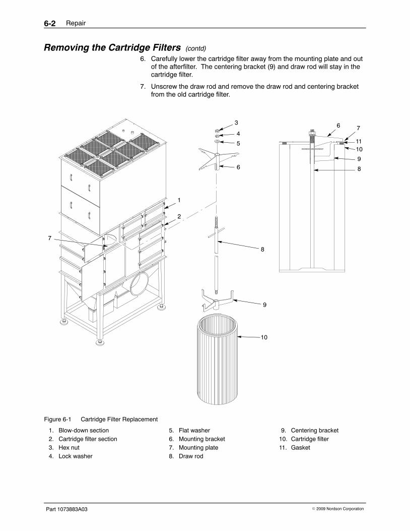
6. Carefully lower the cartridge filter away from the mounting plate and outof the afterfilter. The centering bracket (9) and draw rod will stay in thecartridge filter.
7. Unscrew the draw rod and remove the draw rod and centering bracketfrom the old cartridge filter.
1. Thoroughly clean the sealing surface on the underside of the mountingplate (7). A dirty surface will prevent the cartridge filter gasket fromsealing properly and allow powder to leak into the fan section.
2. Remove the new cartridge filter (10) from its carton and inspect it fordamage. Do not use damaged cartridge filters.
3. Set the centering bracket (9) into the open end of the new cartridge filter.Slide the draw rod (8) through the centering bracket and screw the drawrod into the bottom of the cartridge filter.
4. Center the cartridge filter under the opening in the mounting plate. Usethe draw rod’s T-handle to pull up the cartridge filter against themounting plate.
5. Install the mounting bracket (6) on the draw rod, making sure that theslots in the mounting bracket slip over the T-handle.
6. Install the flat washer (5), lock washer (4), and nut (3) onto the draw rod.Do not tighten the nut at this time.
7. Slip the ends of the mounting bracket into the locating slots around thefilter opening in the mounting plate.
8. Tighten the nut until the mounting and centering brackets are touching.This will compress the filter gasket (11) and seal the cartridge againstthe mounting plate.
Seasoning the Cartridge FiltersNew cartridge filters must be properly seasoned or their performance andlife may be dramatically reduced.
Cartridge filter seasoning is accomplished by introducing virgin powder tothe afterfilter through the cyclone inlet duct. Seasoning requires a minimumof 4.5 kg (10 lb) of virgin powder for each cartridge filter in the afterfilter.
For example, the standard 11250 cfm system uses 15 cartridge filters, andtherefore requires 67.5 kg (150 lb) of virgin powder for the seasoningprocedure.
WARNING: Wear protective clothing, safety goggles, and approvedrespiratory protection whenever handling powder or performingmaintenence or cleaning procedures. Follow the personal protectionrecommendations included on the Material Safety Data Sheets for eachpowder used.
1. Press the EXHAUSTER START button and turn the PULSE ONDEMAND switch to the ON-DEMAND position.
2. Measure the initial average air velocity across the booth part openingsusing a hand-held velometer.
Repair6-4
Part 1073883A03 � 2009 Nordson Corporation
Seasoning the Cartridge Filters(contd)3. Record the cartridge filter and final filter static pressures displayed on
the pressure gauges on the system control panel.
4. Open the transfer pan and the cyclone access doors. This will allow thepowder to be pulled directly into the afterfilter.
5. Lift the AeroDeck panels up and over until they are resting on the slopedsurface of the base. Gradually dump virgin powder onto the floor in frontof the inlet duct opening and allow the powder to be drawn into theextraction duct.
6. Note the cartridge filter static pressure displayed on the pressure gauge.If the pressure is less than 3-in. wc, add more powder until the staticpressure reaches 3-in. wc.
7. Close the cyclone access doors and transfer pan.
8. Record the average air velocity across the booth part openings using ahand-held velometer.
9. Record the cartridge filter and final filter static pressure displayed on thepressure gauge.
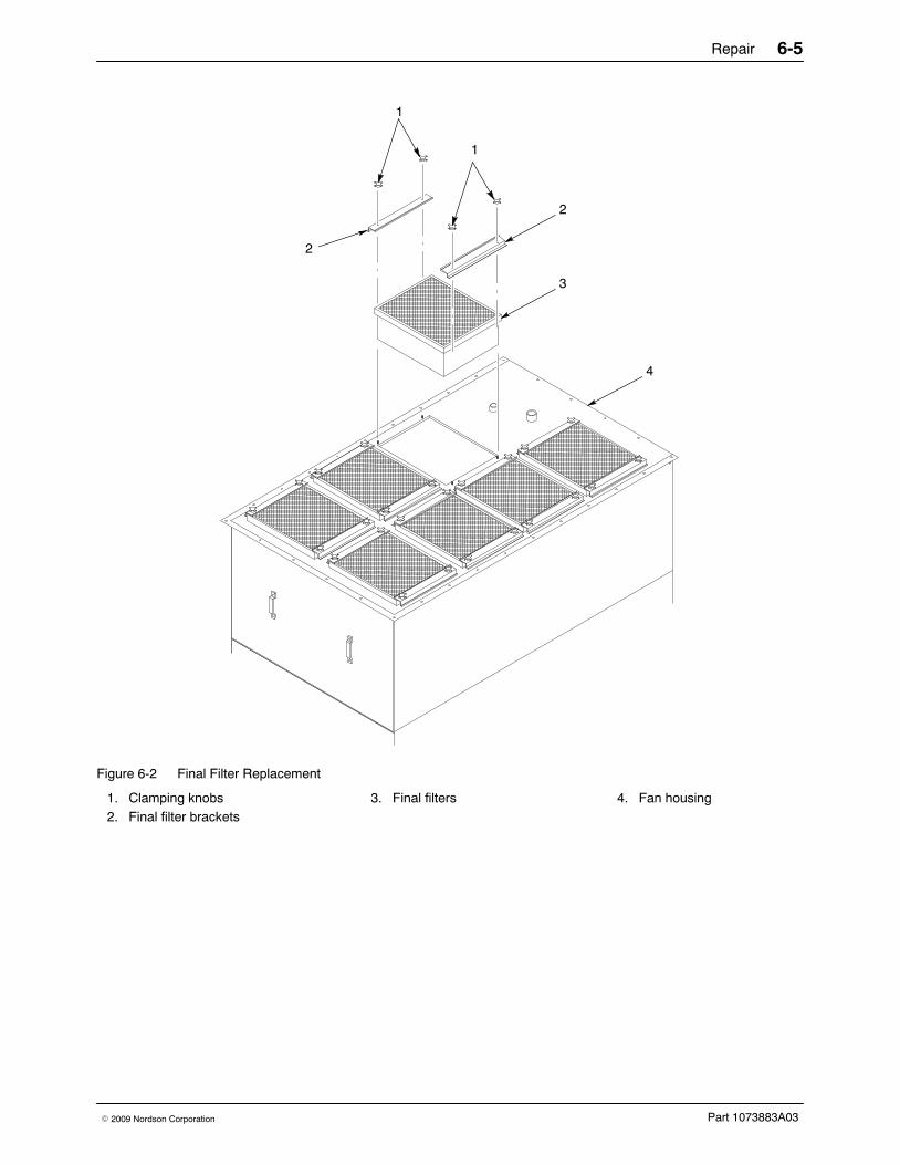
Final Filter Replacement See Figure 6-2.
1. Shut down the powder coating system. Refer to Shutdown in theOperation section for instructions. Shut off and lock out systemelectrical power.
2. Systems with Explosion Suppression Systems Only: Disable theexplosion suppression system. Refer to your explosion suppressionsystem manual for more information.
3. Remove the final filter brackets (2) by removing the clamping knobs (1).
4. Lift the old final filter (3) out of the afterfilter.
5. Inspect the interior of the fan housing (4). If you see large amounts ofpowder inside of the housing, powder is leaking through the cartridgefilters or mounting plate. Fix the leak before starting the system.
6. Remove the new final filter from its carton and inspect it for damage. Donot use damaged final filters.
7. Set the new final filter into the afterfilter.
8. Install the final filter brackets and clamping knobs.
9. Tighten the clamping knobs to compress the final filter evenly on all foursides.
Repair 6-5
Part 1073883A03� 2009 Nordson Corporation
2
2
3
1
1
4
Figure 6-2 Final Filter Replacement
1. Clamping knobs2. Final filter brackets
3. Final filters 4. Fan housing
Repair6-6
Part 1073883A03 � 2009 Nordson Corporation
Pulse Valve Replacement NOTE: Tag each air tube before replacing the pulse valves, or replace onevalve at a time, to avoid connecting the air tubes to the wrong valves.
1. Shut down the powder coating system. Refer to Shutdown in theOperation section for instructions.
2. Shut off and lock out system electrical power.
3. Systems with Explosion Suppression Systems Only: Disable theexplosion suppression system. Refer to your explosion suppressionsystem manual for more information.
4. See Figure 6-3. Open the pulse valve access door.
5. Disconnect the air tubing from the elbow (3).
6. Unscrew the pulse valve (4) from the nipple (2).
7. Unscrew the elbow and nozzle (5) from the pulse valve. Save the elbowand nozzle for reuse.
8. Clean the threads on the nipple, elbow, and nozzle. Wrap 2−3 layers ofnew PTFE tape around the threads.
9. Install the elbow and nozzle onto the new pulse valve.
10. Screw the new pulse valve assembly onto the nipple. Make sure thatwhen tightened the nozzle points straight down into the cartridge filter.
11. Connect the air tubing to the elbow.
1
2 3
4
5
Figure 6-3 Pulse Valve Replacement
1. Access door2. Nipple3. Elbow fitting
4. Pulse valve5. Nozzle
Parts 7-1
Part 1073883A03� 2009 Nordson Corporation
Section 7Parts
Introduction For parts and technical support, call the Nordson Industrial CoatingSystems Customer Service Support Center at (800) 433-9319 or contactyour local Nordson representative.
Parts7-2
Part 1073883A03 � 2009 Nordson Corporation
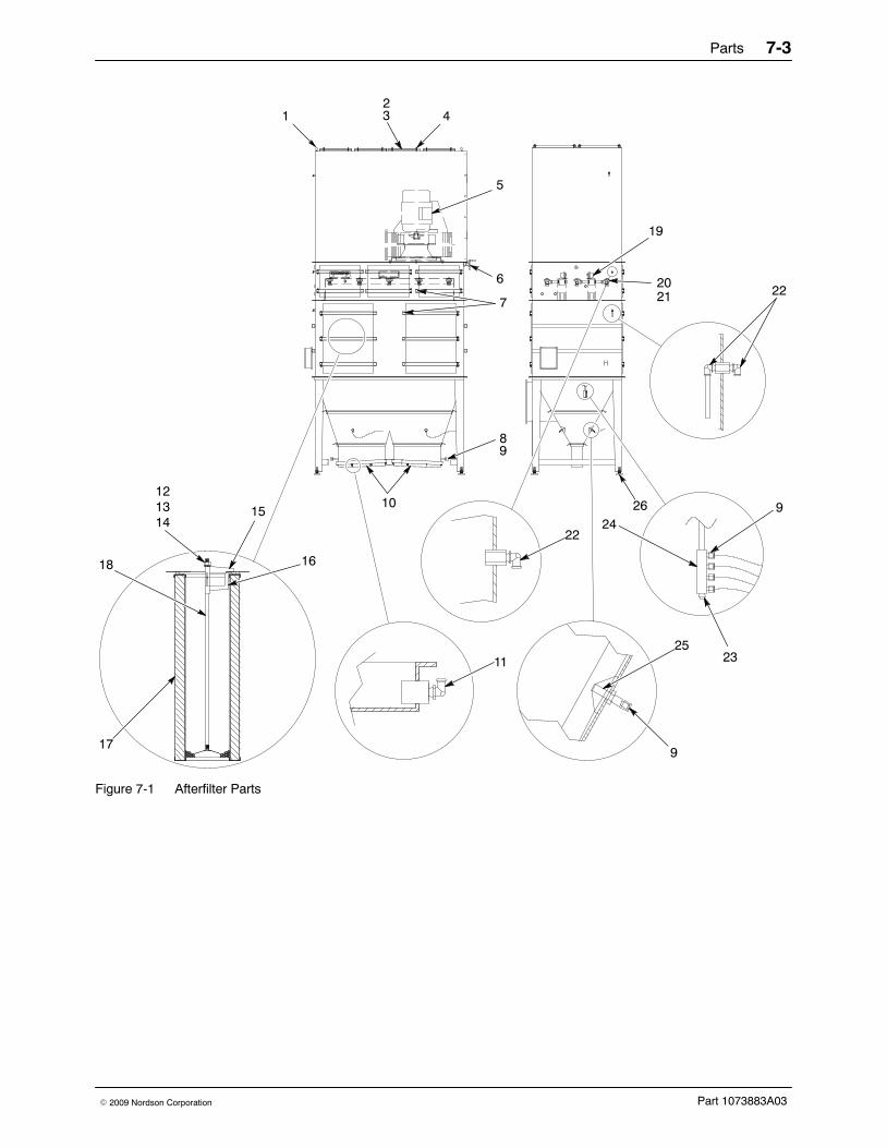
Afterfilter PartsSee Figure 7-1.
Item Part Description Quantity Note1 −−−−−− BOLT, eye, 1.38 ID x 5/8−11 thread x 1.75 in. long 4
2 156995 FILTER, final, 20 x 24 in., internal 7
3 −−−−−− BRACKET, filter retaining 14
4 −−−−−− NUT, hex, flanged, serrated, 3/8−16 110
5 1008635 FAN, assembly, Chicago Blower, 50 hp 1
6 1008295 BAFFLE, plate assembly 1
7 −−−−−− KNOB, 3/8−16 through hole 24
8 244721 PUMP, powder, transfer 0.75 in outlet 2
9 −−−−−− CONNECTOR, male, 10 mm tube x 1/4 in. NPT 8
10 1008128 FLUIDIZING BED 2
11 −−−−−− CONNECTOR, male, elbow, 90�, 10 mm tube x1/4 in. NPT
8 1022416 � WASHER, friction, 0.25 ID x 1.00 in. OD 2 A
9 1022417 � SCREW, pan head, 10−32 x 0.75 in., isoplast 2
NOTE A: The friction washer, part 1022416, must be adhered to the back of the nozzle, part 1014477, before thenozzle is secured to the nozzle positioning bracket.
AR: As Required
4
1
2
9 5
3
6
8
7
Figure 7-2 Gun Blow-Off Parts
Parts 7-5
Part 1073883A03� 2009 Nordson Corporation
Canopy and Base PartsUse the following list to order common replacement parts for the boothcanopy and base.
Part Description Note1014481 VALVE, remote, air operated, 1-in. NPT