41
10SPE@15m (multidrop) & TSN 22.5.2017 Contributors: Kirsten Matheus, BMW Max Turner, BMW Helge Zinner, Continental Markus Plankensteiner, TTtech Craig Gunther, Harman 1

10SPE@15m (multidrop) & TSN
22.5.2017
Contributors:
Kirsten Matheus, BMW
Max Turner, BMW
Helge Zinner, Continental
Markus Plankensteiner, TTtech
Craig Gunther, Harman
1

Introduction
The automotive and commercial vehicle industry as well as industrial automation have identified use cases in which the support of a multidrop scenario for 10SPE@15m would be very useful. The following slides describe expected interrelations between a 10SPE@15m (multidrop and P2P) scenario and IEEE 802.1 AVB/TSN features.
1. Framework
2. AVBgen1 featuresa) Grandmaster clock and time synch
b) Traffic (class) based shaping
c) Stream reservation and stream reservation traffic classes
d) 1722 AVTP (audio transmission)
e) Miscellaneous
3. AVBgen2 featuresa) Qci per stream filtering and policing
b) Redundancy
c) Real-time traffic support
d) Miscellaneous
2

Framework (1)
In case of EPON multidrop the switch in the head node emulates P2P connections to every end nodes (i.e. communication between two end nodes passes via the head node). The communication on the medium is half duplex.
The channel is shared on a time base (TDMA). The timing is organized in the MPCP.
The head node always broadcasts its messages. Additional addressing identifies its validity with the slaves.
3
X „Head node“
„End nodes“
X
Simplified head node switch for bus Ethernet network
with 4 end nodes
MPCP
Reconciliation’
PHY
MAC MAC MAC MAC MAC
Simplified head node switch for switched Ethernet network
with 4 end nodes
X
MAC MAC MACMAC
PHY PHY PHYPHY
Reconciliation
X „Head node“
„End nodes“
Mu
ltid
rop
syst
em
Sw
itch
ed
sy
ste
m

X „Head node“
„End nodes“
100Mbps10Mbps
Topology view Physical ViewLogical View(Layer 2 view)
PHYPins
PHY
Visible: Only one PHY per node,
no stubs, no switches
Visible:
Latency about the same to every node
No collisions possible
Smaller data rate
P2P connection
Framework´(2)
100Mbps
X
10Mbps
No. nodese.g.
PHY X
100Mbps
PHY
PHY
4
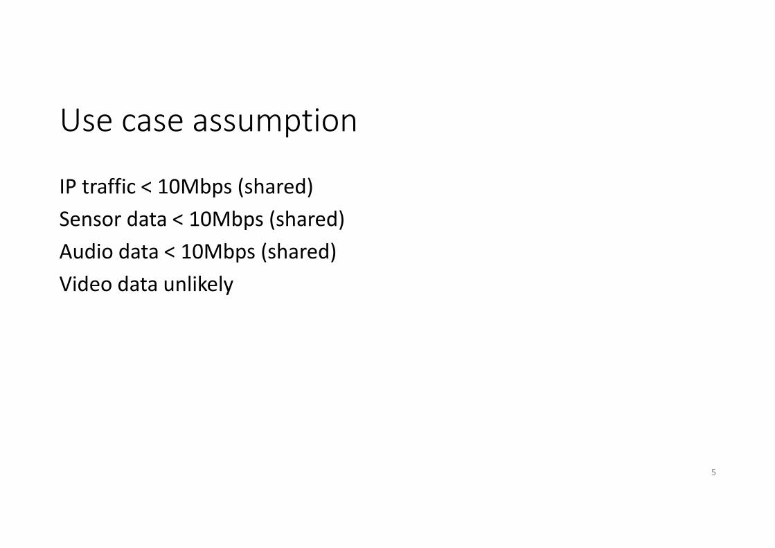
Use case assumption
IP traffic < 10Mbps (shared)
Sensor data < 10Mbps (shared)
Audio data < 10Mbps (shared)
Video data unlikely
5
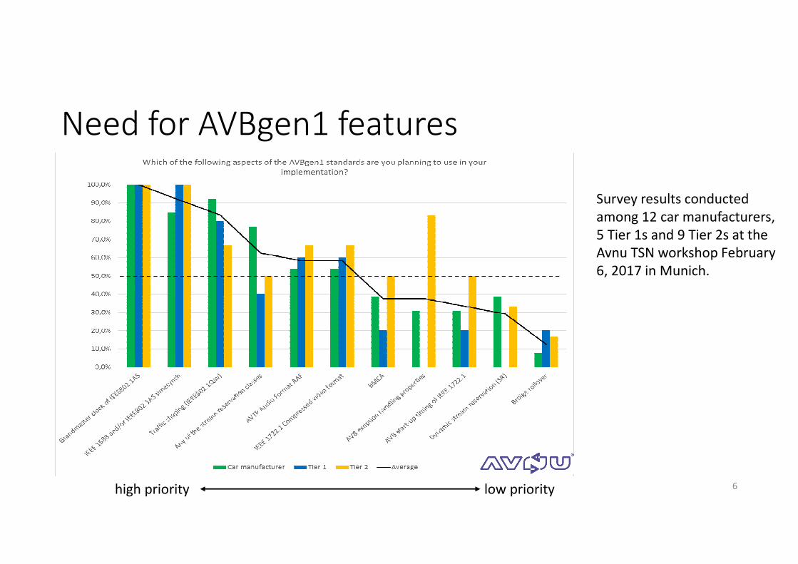
Need for AVBgen1 features
6
Survey results conducted
among 12 car manufacturers,
5 Tier 1s and 9 Tier 2s at the
Avnu TSN workshop February
6, 2017 in Munich.
high priority low priority

Grandmaster Clock and Time Sync
Requires Sync messages from Master (Head Node) to Slave (End Nodes) and pDelay measurements initiated by the Slave (End Nodes)
7
Message sequence for
pDelay measurement
Message sequence for
sync messages
pDelay =
(t4-t1 - (t3-t2))/2
Deviation: ∆t =
t2-(t1+pDelay)
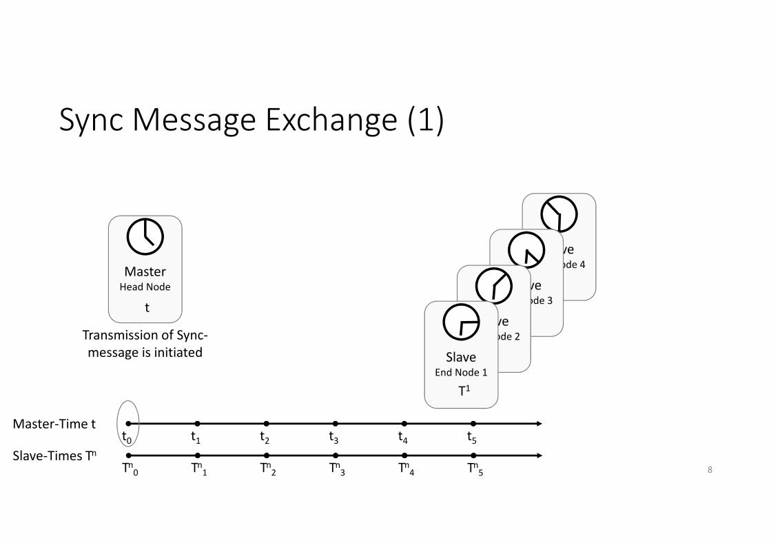
Sync Message Exchange (1)
8
t0 t1 t2 t3 t4 t5
Transmission of Sync-
message is initiated
MasterHead Node
SlaveEnd Node 4
SlaveEnd Node 3
SlaveEnd Node 2
SlaveEnd Node 1
t
T1
Master-Time t
Slave-Times Tn
Tn0 Tn
1 Tn2 Tn
3 Tn4 Tn
5

Master sends
Sync-Message
Sync-Message(id)
Sync Message Exchange (2)
9
MasterHead Node
SlaveEnd Node 4
SlaveEnd Node 3
SlaveEnd Node 2
SlaveEnd Node 1
One message
for all end
nodes!
t0 t1 t2 t3 t4 t5
Master-Time t
t
T1
Slave-Times Tn
Tn0 Tn
1 Tn2 Tn
3 Tn4 Tn
5
Slave-Times Tn
Tn0 Tn
1 Tn2 Tn
3 Tn4 Tn
5
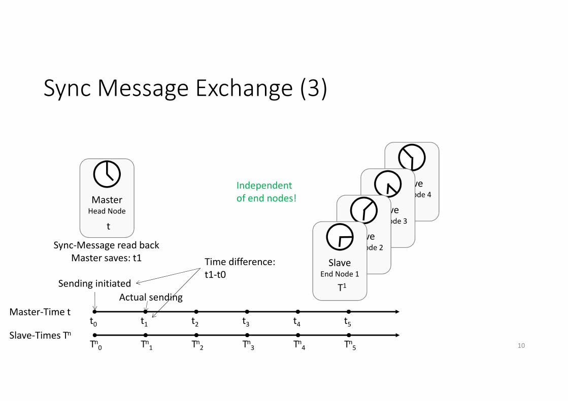
Sync Message Exchange (3)
10
MasterHead Node
SlaveEnd Node 4
SlaveEnd Node 3
SlaveEnd Node 2
SlaveEnd Node 1
Independent
of end nodes!
Sending initiated
Actual sending
Time difference:
t1-t0
Sync-Message read back
Master saves: t1
t0 t1 t2 t3 t4 t5
Master-Time t
t
T1

Sync-Message(id)
Sync-Message(id)
Sync-Message(id)
Sync Message Exchange (4)
11
MasterHead Node
SlaveEnd Node 4
SlaveEnd Node 3
SlaveEnd Node 2
SlaveEnd Node 1
Different Tn2
for every
end node!
Slaves receive
Sync-Message
and save: Tn2
Sync-Message(id)
Master-Time tt0 t1 t2 t3 t4 t5
t
T1
Slave-Times Tn
Tn0 Tn
1 Tn2 Tn
3 Tn4 Tn
5

Sync Message Exchange (5)
12
MasterHead Node
SlaveEnd Node 4
SlaveEnd Node 3
SlaveEnd Node 2
SlaveEnd Node 1
Master-Time tt0 t1 t2 t3 t4 t5
t
T1
Slave-Times Tn
Tn0 Tn
1 Tn2 Tn
3 Tn4 Tn
5
Master sends
FollowUp-Message
FollowUp-Message(id,t1)One message
for all end
nodes!

FollowUp-Message(id,t1)
FollowUp-Message(id,t1)
FollowUp-Message(id,t1)
FollowUp-Message(id,t1)
Sync Message Exchange (6)
13
MasterHead Node
SlaveEnd Node 4
SlaveEnd Node 3
SlaveEnd Node 2
SlaveEnd Node 1
Master-Time tt0 t1 t2 t3 t4 t5
t
T1
Slave-Times Tn
Tn0 Tn
1 Tn2 Tn
3 Tn4 Tn
5
Slaves receive
FollowUp-Message
Different Tn4
for every
end node!

FollowUp-Message(id,t1)
FollowUp-Message(id,t1)
FollowUp-Message(id,t1)
FollowUp-Message(id,t1)
Sync Message Exchange (7)
14
MasterHead Node
SlaveEnd Node 4
SlaveEnd Node 3
SlaveEnd Node 2
SlaveEnd Node 1
Master-Time tt0 t1 t2 t3 t4 t5
t
T1
Slave-Times Tn
Tn0 Tn
1 Tn2 Tn
3 Tn4 Tn
5
Slaves calculate deviation
∆tn= Tn2-(t1+pDelayn)
Different
pDelayn for
every end
node!
In principle, PTP timesync possible also for multidrop
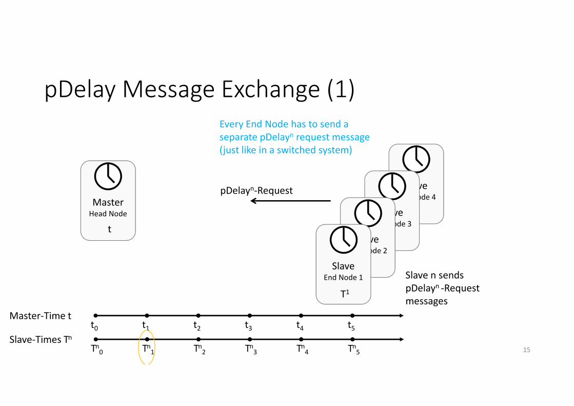
pDelay Message Exchange (1)
15
MasterHead Node
Master-Time tt0 t1 t2 t3 t4 t5
t
T1
Slave-Times Tn
Tn0 Tn
1 Tn2 Tn
3 Tn4 Tn
5
Every End Node has to send a
separate pDelayn request message
(just like in a switched system)
Slave n sends
pDelayn -Request
messages
pDelayn-Request SlaveEnd Node 4
SlaveEnd Node 3
SlaveEnd Node 2
SlaveEnd Node 1
T1

pDelay Message Exchange (2)
16
MasterHead Node
Master-Time tt0 t1 tn
2 t3 t4 t5
Slave-Times Tn
Tn0 Tn
1 Tn2 Tn
3 Tn4 Tn
5
Master receives
pDelayn -Request
messages
pDelayn-RequestSlave
End Node 4
SlaveEnd Node 3
SlaveEnd Node 2
SlaveEnd Node 1
t
T1

pDelay Message Exchange (3)
17
MasterHead Node
Master-Time tt0 t1 t2 t3 t4 t5
t
T1
Slave-Times Tn
Tn0 Tn
1 Tn2 Tn
3 Tn4 Tn
5
pDelayn-Response
Master sends
pDelayn Response
message
SlaveEnd Node 4
SlaveEnd Node 3
SlaveEnd Node 2
SlaveEnd Node 1
T1
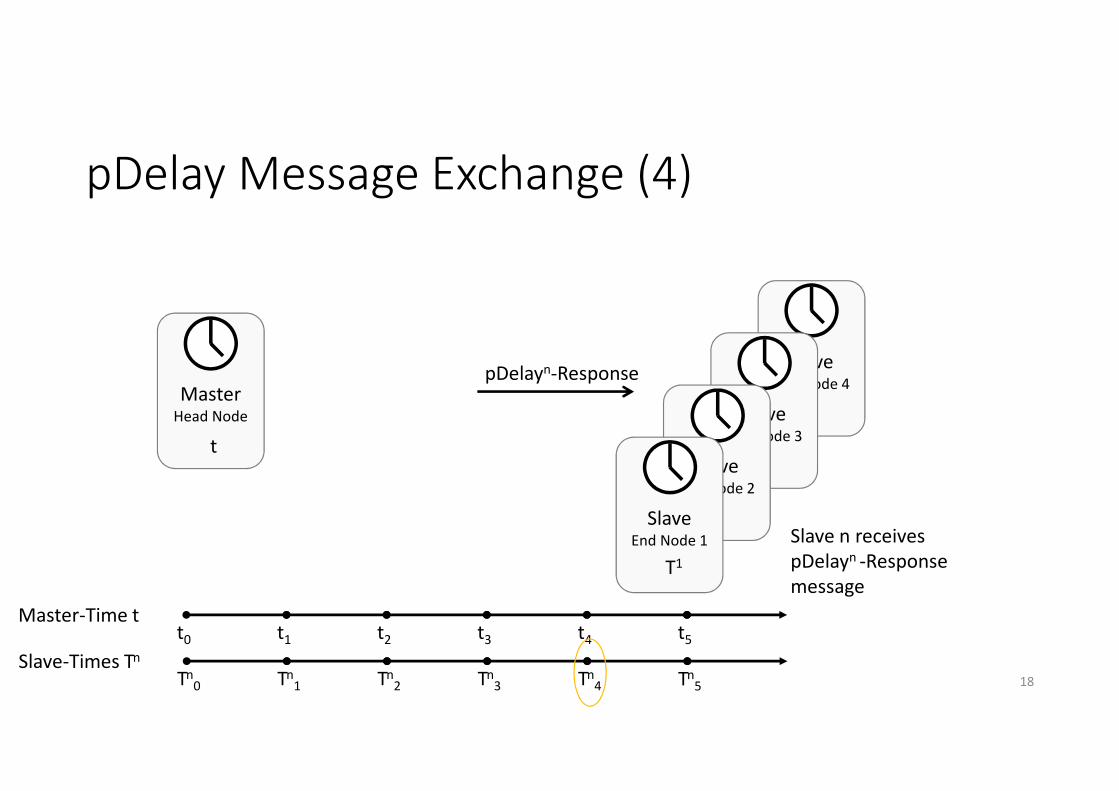
pDelay Message Exchange (4)
18
MasterHead Node
Master-Time tt0 t1 t2 t3 t4 t5
t
Slave-Times Tn
Tn0 Tn
1 Tn2 Tn
3 Tn4 Tn
5
pDelayn-Response
Slave n receives
pDelayn -Response
message
SlaveEnd Node 4
SlaveEnd Node 3
SlaveEnd Node 2
SlaveEnd Node 1
T1

pDelay Message Exchange (5)
19
MasterHead Node
Master-Time tt0 t1 t2 t3 t4 t5
t
Slave-Times Tn
Tn0 Tn
1 Tn2 Tn
3 Tn4 Tn
5
Master sends
pDelayn FollowUp
messages
SlaveEnd Node 4
SlaveEnd Node 3
SlaveEnd Node 2
SlaveEnd Node 1
T1
pDelayn-FollowUp(tn2,tn
3)

pDelay Message Exchange (6)
20
MasterHead Node
Master-Time tt0 t1 t2 t3 t4 t5
t
Slave-Times Tn
Tn0 Tn
1 Tn2 Tn
3 Tn4 Tn
5
Master sends
pDelayn FollowUp
messages
pDelayn-FollowUp(tn2,tn
3)
Slave n receives pDelayn –
FollowUp messages an calculates
pDelayn = Tn4 - Tn
1 - (tn3 - tn
2))/2
SlaveEnd Node 4
SlaveEnd Node 3
SlaveEnd Node 2
SlaveEnd Node 1
T1
Every end node has to calculate a
separate pDelayn value (just like in
a switched system)
pDelay Message Exchange (7)
• Any end node in a multidrop system can initiate a pDelay measurement just like in a switched topology (there also every node has to perform the measurement)
• However, in cars the links are short and the resolution is low
• The transmission delay maximum on the wire was defined as ~94ns on a 15m link*)
• The resolution is 40ns for 100BASE-T1 (due to a 25MHz clock)
• The resolution is 200ns for FlexRay (due to a 5MHz clock)
• The resolution is 1µs for 2Mbps CAN-FD (due to a 1MHz clock)
• For 10SPE (independent of multidrop/P2P) the resolution will likely be larger than 40ns
21*) see IEEE 802.3bp

pDelay Message Exchange (8)
• Example
• On a 3m link segment, pDelay = 31.3ns.
• In a 100BASE-T1 system the resolution is 40ns would likely be measured.
• In a FlexRay or CAN(-FD) system 0s would likely be measured.
• To assume pDelay = 0 might be more efficient
22
For clock synchronization purposes the pDelay measurement is generally not
accurate enough, not even in 100BASE-T1, let alone in CAN-FD or FlexRay. It can be
done in 10SPE@15m (multidrop or not). The question is, whether it is really needed
and useful for the synchronization.
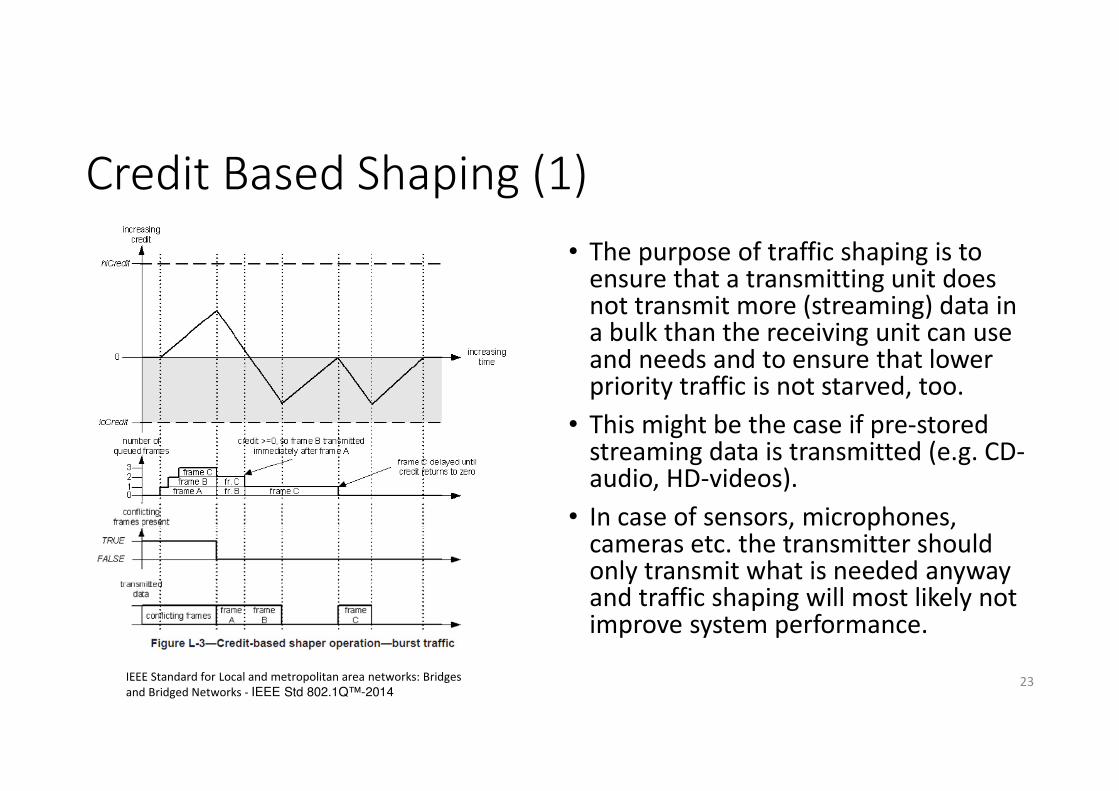
Credit Based Shaping (1)
23IEEE Standard for Local and metropolitan area networks: Bridges
and Bridged Networks - IEEE Std 802.1Q™-2014
• The purpose of traffic shaping is to ensure that a transmitting unit does not transmit more (streaming) data in a bulk than the receiving unit can use and needs and to ensure that lower priority traffic is not starved, too.
• This might be the case if pre-stored streaming data is transmitted (e.g. CD-audio, HD-videos).
• In case of sensors, microphones, cameras etc. the transmitter should only transmit what is needed anyway and traffic shaping will most likely not improve system performance.

Credit Based Shaping (2)
• In principle*), credit based shaping can be used in any end node of 10SPE as well, independent of multidropor P2P (or reach).
• However, the usefulness is questionable
• In a TDMA multidrop scheme the Head Node will ensure that no End Node utilizes the network too much (implicit traffic shaping done by TDMA).
• In the system architecture 10Mbps nodes are likely on the edge. The connection to the core network will likely have a higher data rate (if 10Mbps are fully used, this will not interfere with the rest of the network)
• How many End Nodes with pre-stored audio or video to transmit, will be connected via 10Mbps?
24
X „Head Node“
„End Nodes“
100Mbps10Mbps
*)Might require adaptations in the Qav specification

IEEE 1722 audio transmission (1)
25IEEE Standard for a Transport Protocol for Time-Sensitive Applications in Bridged Local Area Networks - IEEE Std 1722-2016
example for 16bits@48kHz audio and T2-T1=125µs
IEEE 1722 audio transmission (2)
26
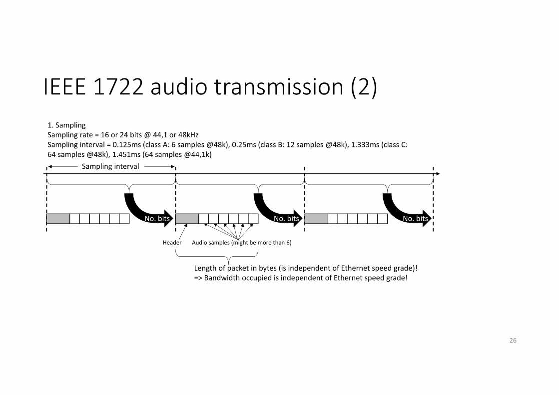
1. Sampling
Sampling rate = 16 or 24 bits @ 44,1 or 48kHz
Sampling interval = 0.125ms (class A: 6 samples @48k), 0.25ms (class B: 12 samples @48k), 1.333ms (class C:
64 samples @48k), 1.451ms (64 samples @44,1k)
Header Audio samples (might be more than 6)
No. bitsNo. bits No. bits
Sampling interval
Length of packet in bytes (is independent of Ethernet speed grade)!
=> Bandwidth occupied is independent of Ethernet speed grade!
IEEE 1722 audio transmission (3)
27
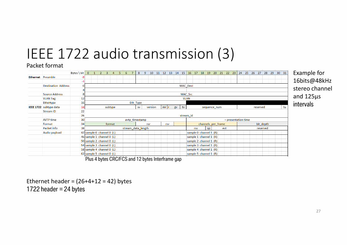
Example for
16bits@48kHz
stereo channel
and 125µs
intervals
Packet format
Plus 4 bytes CRC/FCS and 12 bytes Interframe gap
Ethernet header = (26+4+12 = 42) bytes
1722 header = 24 bytes

IEEE 1722 audio transmission (4)
28
SamplingInterval (T2-T1)
Samplingrate
Audio samples per packet (stereo 16 bits per sample @ 44.1 or 48Hz)
Packet length [in bits](30+12+24)*8+ audio samples*16
Bandwidth used for one stereo channel
Number of stereo streams possible on 10Mbps (75%)
Bandwidth used for 4 audiochannels *)
Class A 125µs 48kHz 2*6=12 720 5.76Mbps 1 7.30Mbps
125µs 44.1kHz 2*6=12 720 5.76Mbps 1 7.17Mbps
Class B 250µs 48kHz 2*12 =24 912 3.65Mbps 2 6.74Mbps
250µs 44.1kHz 2*12 =24 912 3.65Mbps 2 6.40Mbps
Class 64
samples1333µs 48kHz 2*64=128 2576 1.93Mbps 3 3.47Mbps
1451µs 44.1kHz 2*64=128 2576 1.78Mbps 4 3.19Mbps
*) cannot be conducted from table but has to be derived separately
• In principle, it is not really advisable to use Class A and B for audio transmission, as it uses a significant
amount of bandwidth (independent from the speed grade of the system)
• However, all investigated classes can be transmitted over a 10SPE channel as well. Naturally, when the
bandwidth is shared among several users, the designers need to plan the bandwidth use ahead.

Maximum frame sizes for AVB traffic classes
For using the AVB traffic classes for IP packets the payload might indeed be limited for 10SPE (independent of multidrop or P2P or reach).
Class A limits the packet size also in a 100Mbps system!
But would AVB stream reservation be needed in a TDMA scheme, anyway?
If yes, having 10Mbps links needs to be included in the algorithms (see also next slide).
29
Interval time [us] Max. # bytes @100Mbps i.e.
0,08ms/byte with 75% reservable
Max. # bytes @10Mbps i.e.
0,8ms/byte with 75% reservable
No traffic class n/a 1500+30 (+12)=1542*) 1500+30 (+12)=1542**)
Class A 125 1171=42+1129 117=42+75
Class B 250 2343=42+2301 234=42+192
Class 64/1333 1333 12496=42+12454 1249=42+1207
Class 64/1451 1451 13603=42+13561 1360=42+1318
*) Takes about 123.4µs per packet
**) Takes about 1234µs per packet

Dynamic Stream Reservation
• Classic dynamic stream reservation is intended for a plug & play environment where new streams can be added outside the control of the system designer.
• The vehicle network is preplanned. Furthermore, it would be unacceptable in a car, that any feature the customer expects or needs, does not work because there is not sufficient bandwidth available. @BMW dynamic stream reservation is therefore not used, also not for 100Mbps (static stream reservation, yes).
• However, should anyone want to use dynamic stream reservation in an AVB-Cloud that includes 10Mbps links, the algorithms would need to be enhanced (also for P2P and long reach, in a TDMA multidrop system its usefulness is again questionable)
30

Best Master Clock Algorithm (BMCA)
The BMCA allows to dynamically select the GrandMaster clock. It will choose the best clock available in the AVB-cloud.
In cars the network is preconfigured. Even if some options might have a better clock, it might still be advisable to have the same unit provide the Grandmaster in every car. Furthermore, BMCA slows down start-up. @BMW we therefore do not use the BMCA but statically configure, which unit provides the GrandMaster clock.
In general, is it likely that the Ethernet network would have a unit with the Grandmaster connected to the rest of the network by a 10Mbps link? In a multidrop system it is difficult to imagine any unit other than the Head Node as GrandMaster.
31

Miscellaneous
• 1722.1 start-up timing cannot include dependencies with other hierarchically higher management systems (like SOME/IP or the GENIVI Audio manager). Its usefulness as such in automotive use cases is limited. Should its use be desired probably an adaptation of the standard is needed (for 10Mbps as such and for multidrop).
• The implementation of AVB IEEE 1722.1 exception handling process just for testing is not feasible and does not work with the automotive diagnostic protocol UDS.
• Bridge roll over means that the bridge continues providing the 802.1AS time if the Grandmaster clock goes down. Should not be impacted by 10Mbps Ethernet.
32

General remarks on AVGgen2/TSN standards
• The standards are very new and partially even still work in
progress.
• They offer a very large number of diverse new features.
• Many players would like to know, which standards the
automotive industry is really interested in and would like to
use. At this point in time, this is very difficult to say.
• The following slides can just give only a rough idea, where
adaptations for 10Mbps Ethernet might be necessary. It is
NOT a TSN tutorial.
33

Need for TSN features
34
0%
10%
20%
30%
40%
50%
60%
70%
80%
90%
100%
Which of the following aspects of the TSN standards do you expect to use in your
implementations?
Yes Yes, maybe later No
Order of confirmation Order of rejection
Survey results conducted
among 12 car manufacturers,
5 Tier 1s and 9 Tier 2s at the
Avnu TSN workshop February
6, 2017 in Munich.
Lots of yellow �
Lots of insecurity !

Qci, per stream filtering and policing
• The idea of IEEE 802.1Qci is that the incoming traffic can be limited per stream and that some streams can even be blocked. This allows to eliminate the effect of e.g. babbling idiots in the system.
• Again, the 10Mbps-subsystem is likely to be at the edge of the network and connected to the rest of the system by a 100Mbps link, so the risks are limited.
• In a multidrop system, additionally, the TDMA will ensure that no units can send more than has been assigned.
• However, if anyone still wants to use Qci on a 10Mbps link, the possibilities and adaptations need to be discussed.
35
IEEE802.1AS-rev
• The most enticing feature of this specification is probably to be able (directly) switch over the Grandmaster in case the Grandmaster fails as this addresses the topic of redundancy.
• Here the question is again, whether the (alternative) Grandmaster would really be on a unit connected to the rest of the system with a 10Mbps link. Architecturally this might not be the best design.
• Else, why should it not be possible to have a second time domain, or a Grandmaster to switch over to on any unit in the Ethernet network?
36
IEEE 802.1Qbv, Qbu, Qch and 802.3br
• These standards intend to reduce delays and jitter as well as increasing the determinability of traffic in the system.
• In case of a TDMA scheme for the multidrop system, it is already provided what Qbv wants to achieve.
• If it is intended to pass the traffic through the system with continued highest priority after it leaves the 10Mbps network, this needs to be investigated and might require alignment with Qbv. Again, this might not be good system design to try to do so. Before any activity is started, it is recommended to investigate whether this would really be required.
37
Qbv � Time Aware Shaping
Qbu & br � preemption
Qch � synchronized cyclic queuing and drainage
Redundancy Qca and CB
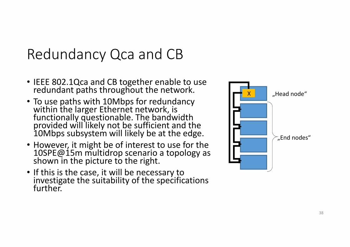
• IEEE 802.1Qca and CB together enable to use redundant paths throughout the network.
• To use paths with 10Mbps for redundancy within the larger Ethernet network, is functionally questionable. The bandwidth provided will likely not be sufficient and the 10Mbps subsystem will likely be at the edge.
• However, it might be of interest to use for the 10SPE@15m multidrop scenario a topology as shown in the picture to the right.
• If this is the case, it will be necessary to investigate the suitability of the specifications further.
38
X „Head node“
„End nodes“

Miscellaneous
• Qcr enables asynchronous traffic shaping
• Qcc allows for per stream (instead of per class) configurable stream reservation
• These specifications currently have a very low acceptance rate and needs to be better understood, what their potential use in the automotive industry is, before any assessment on their usability with 10SPE@15m would be (multidrop or not)
39

Summary
• These slides investigate how the core functionality of AVB/TSN maps to 10SPE Ethernet with and without multidrop in automotive use cases.
• No show stoppers have been identified.
• Most critical is the use of Class A and B with stream reservation for 10SPE (independent of multidrop/P2P or length, and both are not very efficient in 100Mbps system either).
• The TDMA scheme of the multidrop system renders quite a few AVB/TSN functions unnecessary.
• However, discussions with IEEE 802.1 to ensure that adaptations can be made if necessary are recommended.
40

References
• „Avnu Automotive Ethernet AVB Functional and Interoperability Specification - Revision 1.4“ - 12 May 2015
• Avnu Publication “Summary and Interpretation of the Results from the AVB/TSN Workshop Munich February 6, 2017”, 2017
41


