REVISED FINAL REPORT V3.0 AERONAUTICAL IMPACT ASSESSMENT PROPOSED DEVELOPMENT AT 11-27 FROME STREET, ADELAIDE, SA LB00073 Report to: Kyren Group 5 July 2017 The Ambidji Group (A Division of Landrum & Brown) Level 5, 114 Flinders Street, Melbourne VIC 3000, Australia
Transcript
REVISED FINAL REPORT V3.0
AERONAUTICAL IMPACT ASSESSMENT
PROPOSED DEVELOPMENT
AT
11-27 FROME STREET, ADELAIDE, SA
LB00073
Report to:
Kyren Group
5 July 2017
The Ambidji Group(A Division of Landrum & Brown)
Level 5, 114 Flinders Street, Melbourne VIC 3000, Australia
The information contained in this document is confidential and proprietary to Landrum & Brown Worldwide (Aust) Pty. Ltd. Other than for evaluation and governmental
disclosure purposes, no part of this document may be reproduced, transmitted, stored in a retrieval system, or translated into any language in any form by any means without
the written permission of Landrum & Brown.
DOCUMENT RELEASE APPROVAL
Approved for Release: Final Report
Name: Barrie Slingo Title: Senior Associate
Date: 5 July 2017
Distribution: Steven Kotzias
Project Manager Kyren Group
DOCUMENT CONTROL
REV NO
DESCRIPTION DATE Prepared QA
V0.1 Draft Initial Report 21 July 2016 BR BWS
V1.0 Final Report 29 July 2016 BR BWS
V2.0 Revised Final Report 23 March 2017 BR BWS
V3.0 Second Revised Final Report incorporating Lightning Rod
05 July 2017 BR BWS
TABLE OF CONTENTS
1. SIGNIFICANT CONCLUSIONS OF THE STAGE 2 REPORT ........................................ 1
2. INTRODUCTION TO THE STAGE 2 REPORT ............................................................... 2
3. THE PROPOSED DEVELOPMENT SITE LOCATION ................................................... 2
APPENDIX C: GLOSSARY OF AERONAUTICAL TERMS AND ABBREVIATIONS
11-27 Frome Street, Adelaide Client – Kyren Group
The Ambidji Group
5 July 2017 1
1. SIGNIFICANT CONCLUSIONS OF THE STAGE 2 REPORT
The proposed development to a building height of 177.5 m AHD (including 2 m high lightning rod) and a crane height of 182.9 m AHD:
Will infringe the Adelaide Conical Surface estimated as 147 m AHD, by 30.5 m when completed, and by 35.9 m during construction. However, an aeronautical safety study has demonstrated that the penetrations of the conical surface should not impact on the safety, efficiency or regularity of airport operations and is therefore considered likely to be approvable under the Airports (Protection of Airspace) Regulations (APARs);
Will not infringe the Obstacle Limitation Surface (OLS) and Procedures for Air Navigation – Aircraft Operations (PANS-OPS) surfaces of Parafield Airport and RAAF Base Edinburgh;
Will not infringe the Adelaide PANS-OPS lowest surface estimated at 218.7 m AHD, and the RTCC lowest surface of 182.9 m AHD;
Will infringe the clearance requirement of the Adelaide Terminal Area Radar (TAR) by 86 m.
o Airservices Australia may require an engineering analysis to be conducted to confirm if the penetration of the clearance requirement impacts on the performance of the Adelaide TAR; and
o Even if there is an impact on the performance of the TAR, there are other surveillance systems (the Summertown SSR and ADS-B) which can provide alternative surveillance coverage in the Terminal Area Airspace for transponder and ADS-B equipped aircraft;
The performance of the navigation aids and communication facilities in the Adelaide region will not be impacted;
The proposed development location and heights will be referred to aircraft operators for their comments with regard to engine-out contingency procedures, and Adelaide Airport Limited (AAL) will advise if there is an impact and if a variation is required to the building and/or crane heights. Considering the site distance from the airport and numerous other high rise buildings in the CBD, it is highly unlikely that the development will impact on contingency procedures;
Plume rises from the building roof top exhaust systems, if in excess of 4.3 m/s, will require a safety assessment to be undertaken by the Civil Aviation Safety Authority (CASA); and
Cranes (temporary obstacles) will not penetrate the PANS-OPS and RTCC surfaces. However, the cranes do penetrate the Adelaide OLS and would need to be separately approved and the developer must provide timely advice to Adelaide Airport prior to construction so that appropriate Notice to Airmen (NOTAM) may be issued.
11-27 Frome Street, Adelaide Client – Kyren Group
The Ambidji Group
5 July 2017 2
2. INTRODUCTION TO THE STAGE 2 REPORT
The Ambidji Group Pty Ltd has been tasked to prepare an Aeronautical Impact Assessment (AIA) by the Kyren Group for the proposed development at 11-27 Frome Street, Adelaide.
The AIA has been prepared in two stages as follows:
Stage 1 Initial maximum building and crane height assessment; Stage 2 Final report using the actual building and crane height, following confirmation by
the Kyren Group.
Stage 1 has been completed and submitted to Kyren. This report covers Stage 2 and the increased building height of 2 m following the need to install a 2 m lightning rod.
Kyren has confirmed that the proposed building height is 177.5 m AHD, and crane height a maximum of 182.9 m AHD.
The methodology employed for the preparation of this report primarily focuses on the consideration of the key elements of:
the Airports Act 1996 (Part 7.9, Protection of airspace around airports);
the Airports (Protection of Airspace) Regulations 1996;
Civil Aviation (Building Control) Regulations 1988; and
Civil Aviation Safety Regulations (CASR) Part 139 Manual of Standards (MOS), Chapter 7 Obstacle Restriction and Limitation and Chapter 11 Standards for Other Aerodrome Facilities.
The key elements of this Stage 2 report involve an assessment of the following airspace surfaces and procedures to determine the potential impact on prescribed airspace and airport facilities:
the Obstacle Limitation Surfaces (OLS);
the Procedures for Air Navigation Services – Aircraft Operations (PANS OPS) Surfaces;
the Radar Terrain Clearance Chart (RTCC) surfaces;
the Standards for Siting and Clearance Areas for Airways Facilities on Airports;
flight paths for engine inoperative contingency procedures; and
the requirement for exhaust plume rise assessment by CASA.
A drawing of the Building Elevation is shown in Appendix A.
A drawing of the site plan and coordinates is shown in Appendix B.
A Glossary of Aeronautical Terms and Abbreviations is shown in Appendix C.
3. THE PROPOSED DEVELOPMENT SITE LOCATION
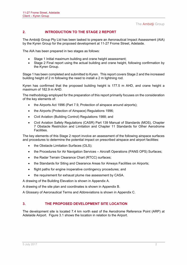
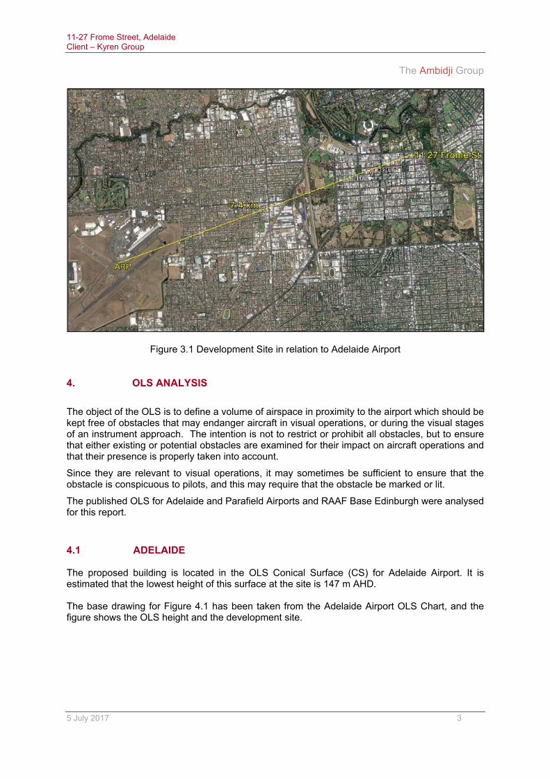
The development site is located 7.4 km north east of the Aerodrome Reference Point (ARP) at Adelaide Airport. Figure 3.1 shows the location in relation to the Airport.
11-27 Frome Street, Adelaide Client – Kyren Group
The Ambidji Group
5 July 2017 3
Figure 3.1 Development Site in relation to Adelaide Airport
4. OLS ANALYSIS
The object of the OLS is to define a volume of airspace in proximity to the airport which should be kept free of obstacles that may endanger aircraft in visual operations, or during the visual stages of an instrument approach. The intention is not to restrict or prohibit all obstacles, but to ensure that either existing or potential obstacles are examined for their impact on aircraft operations and that their presence is properly taken into account.
Since they are relevant to visual operations, it may sometimes be sufficient to ensure that the obstacle is conspicuous to pilots, and this may require that the obstacle be marked or lit.
The published OLS for Adelaide and Parafield Airports and RAAF Base Edinburgh were analysed for this report.
4.1 ADELAIDE
The proposed building is located in the OLS Conical Surface (CS) for Adelaide Airport. It is estimated that the lowest height of this surface at the site is 147 m AHD.
The base drawing for Figure 4.1 has been taken from the Adelaide Airport OLS Chart, and the figure shows the OLS height and the development site.
11-27 Frome Street, Adelaide Client – Kyren Group
The Ambidji Group
5 July 2017 4
Figure 4.1 - Development site in relation to the OLS surfaces (from Adelaide Airport OLS Chart)
The building height of 177.5 m AHD and the crane height of 182.9 m AHD will penetrate the OLS CS by 30.5 m and 35.9 m respectively.
There are conditions for allowing the penetration of the CS and these are discussed in Section 7 of this report, which also includes an Aeronautical Study which shows that the proposed development “would not adversely affect safety or significantly affect the regularity of operations of aeroplanes.”
Aeronautical studies and safety cases prepared for other high rise developments in the Adelaide CBD have resulted in approvals to penetrate the OLS Conical Surface.
4.2 PARAFIELD
The OLS Inner Horizontal, Conical, Approach and Take-off surfaces for RWY 03L/21R are published for Parafield. The conical surface is contained within 6 km of the airport, and as the site is 15 km from the airport, the conical surface is not impacted. The approach and take-off surfaces for the RWY pass well to the west of the development site.
The OLS for Parafield are shown in Figure 4.2. Base data is extracted from the Parafield draft Master Plan.
The Parafield OLS surfaces are not penetrated.
11-27 Frome Street, Adelaide Client – Kyren Group
The Ambidji Group
5 July 2017 5
Figure 4.2 - Development site in relation to the Parafield OLS surfaces (from Parafield Airport draft Master Plan)
4.3 RAAF BASE EDINBURGH
The OLS for RAAF Base Edinburgh extends to approximately 15 km from the Aerodrome Reference Point (ARP), and the building development is over 24 km from the base.
The RAAF Base Edinburgh OLS surfaces are not penetrated.
11-27 Frome Street, Adelaide Client – Kyren Group
The Ambidji Group
5 July 2017 6
5. PANS-OPS ANALYSIS
This analysis considers the PANS OPS surfaces of Adelaide and Parafield airports and RAAF Base Edinburgh.
PANS OPS surfaces detail essential areas and obstacle clearance requirements for the achievement of safe, regular instrument flight operations. The instrument flight procedures enable pilots to either descend from the high en-route environment of cruise type flight to establish visual contact with the landing runway, or climb from the runway to the en-route environment, with a prescribed safe margin above terrain and obstacles, by use of aircraft instruments and radio navigation aids or GPS in conditions where the pilot cannot maintain visual contact with the terrain and obstacles due to inclement weather conditions or at night.
The analysis of the impact by the proposed building development was undertaken with respect to the Instrument Approach and Departure procedures, as published in the Australian Aeronautical Information Publication, Departures and Approach Procedures (AIP DAP) effective 26 May 2016, associated Aeronautical Information Circulars (AIC), Aeronautical Information Supplements and relevant NOTAMS.
Circling Minima, Minimum Sector Altitudes, and Standard Instrument Departure (SID) procedures are also included in the PANS OPS analysis.
5.1 ADELAIDE The lowest PANS-OPS surface over the site is 218.7 m AHD. This has been calculated by reference to an extract from the Adelaide Airport Limited PANS-OPS chart shown in Figure 5.1. All heights on this chart are in m AHD and the development site is also shown. The building height of 177.5 m AHD and crane height of 182.9 m AHD are below the PANS-OPS surface height.
5.2 PARAFIELD The PANS-OPS surfaces for Parafield Airport are established for RWY 03L/21R, and are to the North and West of the airport, well clear of the development site which is 14 km to the south. The Parafield PANS-OPS surfaces are not penetrated by the proposed building development. 5.3 RAAF BASE EDINBURGH
The PANS-OPS surfaces for the RAAF Base Edinburgh are located to the North of the base.
The RAAF Base Edinburgh PANS-OPS surfaces are not penetrated by the proposed building development.
6. RTCC ANALYSIS The RTCC is used by Adelaide Air Traffic Controllers for altitude assignment in the Adelaide Terminal Airspace when radar vectoring aircraft. Although the surfaces are published in metres AHD by AAL, for operational use the surfaces plus a 1000 ft Minimum Obstacle Clearance (MOC) are displayed at ATC workstations. An extract of the Adelaide RTCC chart is shown in Figure 6.1. The RTCC surfaces are shown, as well as the development site. Although the RTCC surface heights are blurred on the chart, the RTCC surface at the site is 182.9 m (600 ft) AHD, and to the west of the yellow line the height is 152.4 (500 ft) AHD.
Figure 6.1- RTCC surfaces and the development site.
11-27 Frome Street, Adelaide Client – Kyren Group
The Ambidji Group
5 July 2017 8
The building height of 177.5 m AHD and crane height of 182.9 m AHD do not penetrate the RTCC height of 182.9 m, which is the limiting airspace surface over the development site. Penetrations of the RTCC surface are not permitted (by buildings and cranes), as the increased radar vectoring height would impact on the ability of ATC to radar vector aircraft and could result adversely on the regularity of operations. If, for example, the RTCC surface at the site was increased by 30 m (100 ft), this revised surface would extend almost to the boundary of Adelaide Airport, as the RTCC surface is 3 nm radius of the highest obstacle.
7. PENETRATION OF THE CONICAL SURFACE - AERONAUTICAL STUDY
ICAO Airport Services Manual Part 6 Control of Obstacles states in Para 1.2.2.4:
In assessing the operational effect of proposed new construction, tall structures would not be of immediate significance if they are proposed to be located in:
a) An area already substantially obstructed by terrain or existing structures of equivalent height
b) An area which would be safely avoided by prescribed procedures associated with navigational guidance where appropriate
The Conical Surface can be penetrated in accordance with the recommendations of ICAO Doc ANNEX 14 Volume 1 Aerodrome Design and Operations, Para 4.2.20, which states:
New objects or extensions of existing objects should not be permitted above the Conical Surface and the Inner Horizontal Surface except when, in the opinion of the appropriate authority, an object would be shielded by an existing immovable object, or after an aeronautical study it is determined that the object would not adversely affect safety or significantly affect the regularity of operations of aeroplanes.
As part of this assessment, a basic aeronautical study has been conducted by the consultants to show that the proposed development to a height of 177.5 m AHD when completed and 182.9 m AHD during construction:
is located in “an area which would be safely avoided by prescribed procedures associated with navigational guidance where appropriate”; and
“would not adversely affect safety or significantly affect the regularity of operations of aeroplanes.”
7.1 AERONAUTICAL STUDY PRECEDENTS
It is common for both the Inner Horizontal and Conical Surfaces to be penetrated at many airports in the world, especially those located close to metropolitan areas.
The control towers at most of the new airport developments in Asia (Bangkok, Kuala Lumpur, Jakarta, Singapore, Incheon, Beijing etc.), and Brisbane in Australia all penetrate the Inner Horizontal Surface.
Numerous penetrations of both the Inner Horizontal and Conical Surfaces occur in the vicinity of Adelaide Airport. The Westpac Bank building (186 m AHD), located in the Adelaide CBD (760 m south west of the proposed development) penetrates the Conical Surface by approximately 70 m.
11-27 Frome Street, Adelaide Client – Kyren Group
The Ambidji Group
5 July 2017 9
7.2 IMPACT ON INSTRUMENT APPROACH PROCEDURES
The Inner Horizontal and Conical Surfaces were originally established by ICAO to protect the obstacle clearance of aircraft circling the airport in visual flight conditions prior to landing. When these surfaces were first established in the 1950s and 1960s, the majority of airports and aircraft were not equipped for straight in approaches, and circling approaches were necessary.
With the implementation and extensive use of procedures for approaches aligned with the runway (ILS, RNAV, GNSS, GBAS, RNP, VOR and Locator), the use of circling approaches has decreased considerably. At many airports the restrictions imposed by noise avoidance procedures prevent the use of circling approaches.
All of the Adelaide Airport Runways are served by published straight in approaches as follows:
RWY 23 ILS, RNAV (RNP and GNSS), VOR
RWY 05 RNAV (RNP and GNSS), VOR
RWY 12 RNAV (GNSS), VOR
RWY 30 RNAV (GNSS), VOR
Circling approaches would only be required for aircraft initially making straight in approaches in the unlikely event of a change of runway due to significant weather (mainly wind velocity) changes or changes in serviceability of ground or airborne navigation equipment.
DME and GNSS arrival procedures are published for arrivals from the South East through West to North West, and for arrivals from the East to East South East. A circling approach would normally be required when visual conditions are established following a DME or GNSS arrival procedure.
7.3 EXAMINATION OF CIRCLING APPROACHES
The following restrictions apply to circling approaches at Adelaide which are published in the AIP DAP:
“Circling is not authorised for all of the RNAV (RNP) approach procedures”
For all other approach procedures, the charts are marked with the following restriction “No circling south of RWY 05/23 beyond 4 DME or beyond 3 nm from the thresholds of RWYs 05, 23 and 30”. This no circling area is shown in Figure 7.1.
Figure 7.1- Adelaide no circling area and the development site location
11-27 Frome Street, Adelaide Client – Kyren Group
The Ambidji Group
5 July 2017 10
The development site is located the following distances from the DME and RWY Thresholds:
The development site location is also shown in Figure 7.1, and is located in the no circling area. As such it is in:
“an area which would be safely avoided by prescribed procedures associated with navigational guidance where appropriate”; and
“would not be of immediate significance”
7.4 CONCLUSIONS OF THE AERONAUTICAL STUDY
As the development site is located in the no circling area, and is below the PANS-OPS and RTCC surfaces, the penetration of the OLS Conical Surface:
“would not adversely affect safety or significantly affect the regularity of operations of aeroplanes.”
8. RADAR PERFORMANCE IMPACT
The Adelaide Airport Terminal Area Radar (TAR), comprising of Primary Surveillance Radar (PSR) and Secondary Surveillance Radar (SSR) is located on the airport 7.62 km south west of the building site, at an antenna elevation of 28 m AHD.
There is another SSR located at Summertown, 10.51 km to the south east of the building site, at an antenna elevation of 654 m AHD.
8.1 CLEARANCE REQUIREMENTS FOR RADARS
CASA Manual of Standards (MOS) Part 139 Aerodromes publishes the clearance requirements for radars. The section of the MOS that applies to the Frome St site is:
11.1.14.4
The following clearance requirements are to be maintained:
(a) No intrusion within 1 km of the radar into a height surface 5 m below the bottom of the antenna. No intrusion between the radar and the possible location of any desired targets, i.e. roughly speaking above 0.5 degrees elevation at any distance.
(b) No metallic or other electrical reflective surfaces anywhere which subtend an angle of more than 0.5 degrees when viewed from the radar, e.g. fences, power lines, tanks as well as many buildings. All overhead power lines within 1 km must be aligned radially from the radar or be located at least 10 degrees below horizontal from the antenna.
8.2 CLEARANCE REQUIREMENTS FOR THE ADELAIDE AIRPORT TAR
The elevation of the Adelaide airport TAR antenna is 28 m AHD, and the distance to the building site is 7620 m. The elevation of a 0.5° plane from the antenna at the site is:
7620 x Tan 0.5° = 66.5 m + TAR elevation of 28 m = 94.5 m.
11-27 Frome Street, Adelaide Client – Kyren Group
The Ambidji Group
5 July 2017 11
As the building height is 177.5 m AHD, the building will penetrate the Adelaide TAR clearance plane by 83 m.
Airservices Australia may require an engineering analysis to be undertaken to determine what impact this penetration would have on the performance of the Adelaide TAR. If this is done by Airservices the developer would be charged. Ambidji can also provide a qualified radar engineer to undertake this task under commercial arrangements with the developer.
There are numerous other high rise buildings in the CBD which also penetrate the Adelaide TAR clearance plane and do not appear to impact on the radar performance.
If the Adelaide TAR performance is impacted, there are other airspace surveillance systems that would minimise any impact. These are:
The Summertown SSR, but this radar will only provide surveillance of transponder equipped aircraft; and
Automatic Dependant Surveillance – Broadcast (ADS-B) surveillance is also provided for ADS-B equipped aircraft in the Adelaide terminal airspace but only for ADS-B equipped aircraft.
By regulation, a high percentage of aircraft operating in the Adelaide Terminal Area would be equipped with transponders and ADS-B.
8.3 CLEARANCE REQUIREMENTS FOR THE SUMMERTOWN SSR
This radar is located 10.51 km from the building site, at an elevation of 654 m AHD, which is above the building height, and the building will not penetrate the clearance requirements for this radar.
8.4 CONCLUSIONS OF RADAR CLEARANCE REQUIREMENTS
The building height of 177.5 m AHD will penetrate the clearance requirement of the Adelaide TAR by 83 m. Airservices Australia may require an engineering analysis to be conducted to confirm if the penetration of the clearance requirement impacts on the performance of the Adelaide TAR. Even if there is an impact on the performance of the TAR, there are other surveillance systems (the Summertown SSR and ADS-B) which can provide alternative surveillance coverage for transponder and ADS-B equipped aircraft. The building will not penetrate the clearance requirements of the Summertown SSR.
9. NAVIGATION AID PERFORMANCE IMPACT There are a number of navigation aids installed at Adelaide Airport, including ILS, VOR and DME. The Building Restricted Areas (BRA) specified in the Airservices Australia document Navigation Aid Building Restricted Areas and Siting Guidance AEI-7.1613 Issue 2 contain building development limitations. The BRAs for the ILS, VOR and DME are less than 3000 m from the airport boundary. As the development site is 5870 m from the nearest airport boundary, the BRAs for all of the airport navigation aids will not be impacted.
Aircraft operators are required to implement contingency procedures for engine inoperative flight paths. These procedures, whilst requiring approval by CASA, are not available publicly.
AAL will refer the proposed development location and heights to aircraft operators for their comments, and AAL will advise if there is an impact and if a variation is required to the building and/or crane heights.
Considering the site distance from the airport and numerous other high rise buildings in the CBD, it is highly unlikely that the Frome Street development will impact on the contingency procedures.
11. PLUME RISE ASSESSMENT CASA Advisory Circular 139-5 (1) dated November 2012 requires that all plume rises in excess of 4.3 m/s are submitted to CASA for operational assessment to determine if there is a hazard to aircraft operations.
Plume rises from the building roof top exhaust systems have not yet been advised, but if these will be in excess of 4.3 m/s, an assessment will be required by CASA.
12. CONCLUSIONS
This Stage 2 of the AIA concludes that:
The proposed development to a building height of 177.5 m AHD and a crane height of 182.9 m AHD will infringe Prescribed Airspace at Adelaide Airport, specifically the Conical Surface estimated as 147 m AHD, by 30.5 m when completed, and by 35.9 m during construction;
An aeronautical safety study has demonstrated that the penetrations of the conical surface should not impact on the safety, efficiency or regularity of airport operations and is therefore considered likely to be approvable under the Airports (Protection of Airspace) Regulations (APARs);
The proposed development to a building height of 177.5 m AHD and a crane height of 182.9 m AHD will not penetrate the PANS-OPS lowest surface over the building site, estimated as 218.7 m AHD.
The proposed development to a building height of 177.5 m AHD and a crane height of 182.9 m AHD will not penetrate the RTCC lowest surface of 182.9 m AHD over the building site.
The RTCC surface of 182.9 m AHD is the limiting airspace surface height at the site location. All proposed buildings and cranes will not normally be approved to exceed the RTCC surface.
The building height of 177.5 m AHD will penetrate the clearance requirement of the Adelaide TAR by 83 m.
o Airservices Australia may require an engineering analysis to be conducted to confirm if the penetration of the clearance requirement impacts on the performance of the Adelaide TAR.
o Even if there is an impact on the performance of the TAR, there are other surveillance systems (the Summertown SSR and ADS-B) which can provide alternative surveillance coverage in the Terminal Area Airspace for transponder and ADS-B equipped aircraft.
11-27 Frome Street, Adelaide Client – Kyren Group
The Ambidji Group
5 July 2017 13
The performance of the navigation aids and communication facilities in the Adelaide region will not be impacted;
AAL will refer the proposed development location and heights to aircraft operators for their comments with regard to engine-out contingency procedures, and will advise if there is an impact and if a variation is required to the building and/or crane heights. Considering the site distance from the airport and numerous other high rise buildings in the CBD, it is highly unlikely that the development will impact on contingency procedures.
Plume rises from the building roof top exhaust systems if in excess of 4.3 m/s, will require a safety assessment by CASA.
Cranes (temporary obstacles) will not penetrate the PANS-OPS and RTCC surfaces. However, the cranes do penetrate the Adelaide OLS and would need to be separately approved and the developer must provide timely advice to Adelaide Airport prior to construction so that appropriate NOTAMs may be issued.
11-27 Frome Street, Adelaide Client – Kyren Group
The Ambidji Group
5-Jul-17 Appendix
APPENDIX A
BUILDING ELEVATION
11-27 Frome Street, Adelaide Client – Kyren Group
The Ambidji Group
5-Jul-17 Appendix
APPENDIX B
SITE PLAN AND COORDINATES
11-27 Frome Street, Adelaide Client – Kyren Group
The Ambidji Group
5-Jul-17 Appendix
APPENDIX C
GLOSSARY OF AERONAUTICAL TERMS AND ABBREVIATIONS
To facilitate the understanding of aviation terminology used in this report, the following is a glossary of terms and acronyms that are commonly used in aeronautical impact assessments and similar aeronautical studies.
AC (Advisory Circulars) are issued by CASA and are intended to provide recommendations and guidance to illustrate a means, but not necessarily the only means, of complying with the Regulations.
Aeronautical study is a tool used to review aerodrome and airspace processes and procedures to ensure that safety criteria are appropriate.
AIPs (Aeronautical Information Publications) are publications promulgated to provide operators with aeronautical information of a lasting character essential to air navigation. They contain details of regulations, procedures and other information pertinent to flying and operation of aircraft. In Australia, AIPs may be issued by CASA or Airservices Australia.
Air routes exist between navigation aid equipped aerodromes or waypoints to facilitate the regular and safe flow of aircraft operating under IFR.
Airservices Australia is the Australian government-owned corporation providing safe and environmentally sound air traffic management and related airside services to the aviation industry.
Altitude is the vertical distance of a level, a point or an object, considered as a point, measured from mean sea level.
ATC (Air Traffic Control) service is a service provided for the purpose of:
a. preventing collisions: 1. between aircraft; and 2. on the manoeuvring area between aircraft and obstructions; and
b. expediting and maintaining an orderly flow of air traffic.
CASA (Civil Aviation Safety Authority) is the Australian government authority responsible under the Civil Aviation Act 1988 for developing and promulgating appropriate, clear and concise aviation safety standards. As Australia is a signatory to the ICAO Chicago Convention, CASA adopts the standards and recommended practices established by ICAO, except where a difference has been notified.
CASR (Civil Aviation Safety Regulations) are promulgated by CASA and establish the regulatory framework (Regulations) within which all service providers must operate.
Civil Aviation Act 1988 (the Act) establishes the CASA with functions relating to civil aviation, in particular the safety of civil aviation and for related purposes.
11-27 Frome Street, Adelaide Client – Kyren Group
The Ambidji Group
5-Jul-17 Appendix
ICAO (International Civil Aviation Organization) is an agency of the United Nations which codifies the principles and techniques of international air navigation and fosters the planning and development of international air transport to ensure safe and orderly growth. The ICAO Council adopts standards and recommended practices concerning air navigation, its infrastructure, flight inspection, prevention of unlawful interference, and facilitation of border-crossing procedures for international civil aviation. In addition, the ICAO defines the protocols for air accident investigation followed by transport safety authorities in countries signatory to the Convention on International Civil Aviation, commonly known as the Chicago Convention. Australia is a signatory to the Chicago Convention.
IFR (Instrument Flight Rules) are rules applicable to the conduct of flight under IMC. IFR are established to govern flight under conditions in which flight by outside visual reference is not safe. IFR flight depends upon flying by reference to instruments in the flight deck, and navigation is accomplished by reference to electronic signals. It is also referred to as, “a term used by pilots and controllers to indicate the type of flight plan an aircraft is flying,” such as an IFR or VFR flight plan.
IMC (Instrument Meteorological Conditions) are meteorological conditions expressed in terms of visibility, distance from cloud and ceiling, less than the minimum specified for visual meteorological conditions. LSALT (Lowest Safe Altitudes) are published for each low level air route segment. Their purpose is to allow pilots of aircraft that suffer a system failure to descend to the LSALT to ensure terrain or obstacle clearance in IMC where the pilot cannot see the terrain or obstacles due to cloud or poor visibility conditions. It is an altitude that is at least 1,000 feet above any obstacle or terrain within a defined safety buffer region around a particular route that a pilot might fly. MOS (Manual of Standards) comprises specifications (Standards) prescribed by CASA, of uniform application, determined to be necessary for the safety of air navigation. NOTAMs (Notices to Airmen) are notices issued by the NOTAM office containing information or instruction concerning the establishment, condition or change in any aeronautical facility, service, procedure or hazard, the timely knowledge of which is essential to persons concerned with flight operations. Obstacles. All fixed (whether temporary or permanent) and mobile objects, or parts thereof, that are located on an area intended for the surface movement of aircraft or that extend above a defined surface intended to protect aircraft in flight.
OLS (Obstacle Limitation Surfaces) are a series of planes associated with each runway at an aerodrome that defines the desirable limits to which objects may project into the airspace around the aerodrome so that aircraft operations may be conducted safely.
PANS-OPS (Procedures for Air Navigation Services - Aircraft Operations) is an Air Traffic Control term denominating rules for designing instrument approach and departure procedures. Such procedures are used to allow aircraft to land and take off under Instrument Meteorological Conditions (IMC) or Instrument Flight Rules (IFR). ICAO document 8668-OPS/611 (volumes 1 and 2) outlines the principles for airspace protection and procedure design which all ICAO signatory states must adhere to. The regulatory material surrounding PANS-OPS may vary from country to country.
PANS OPS Surfaces. Similar to an Obstacle Limitation Surface, the PANS-OPS protection surfaces are imaginary surfaces in space which guarantee the aircraft a certain minimum obstacle clearance. These surfaces may be used as a tool for local governments in assessing building development. Where buildings may (under certain circumstances) be permitted to penetrate the OLS, they cannot be permitted to penetrate any PANS-OPS surface, because the purpose of these
11-27 Frome Street, Adelaide Client – Kyren Group
The Ambidji Group
5-Jul-17 Appendix
surfaces is to guarantee pilots operating under IMC an obstacle free descent path for a given approach.
Prescribed airspace is an airspace specified in, or ascertained in accordance with, the Regulations, where it is in the interests of the safety, efficiency or regularity of existing or future air transport operations into or out of an airport for the airspace to be protected. The prescribed airspace for an airport is the airspace above any part of either an OLS or a PANS OPS surface for the airport and airspace declared in a declaration relating to the airport.
Regulations (Civil Aviation Safety Regulations)
VFR (Visual Flight Rules) are rules applicable to the conduct of flight under VMC. VFR allow a pilot to operate an aircraft in weather conditions generally clear enough to allow the pilot to maintain visual contact with the terrain and to see where the aircraft is going. Specifically, the weather must be better than basic VFR weather minima. If the weather is worse than VFR minima, pilots are required to use instrument flight rules.
VMC (Visual Meteorological Conditions) are meteorological conditions expressed in terms of visibility, distance from cloud and ceiling, equal or better than specified minima.
11-27 Frome Street, Adelaide Client – Kyren Group
The Ambidji Group
5-Jul-17 Appendix
ABBREVIATIONS Abbreviations used in this report, and the meanings assigned to them for the purposes of this report are detailed in the following table.
Abbreviation Meaning
AC Advisory Circular (document support CAR 1998)
ACFT Aircraft
AD Aerodrome
AHD Australian Height Datum
AHT Aircraft height
AIP Aeronautical Information Publication
Airports Act Airports Act 1996, as amended
AIS Aeronautical Information Service
Alt Altitude
AMSL Above Mean Sea Level
APARs Airports (Protection of Airspace) Regulations, 1996 as amended
ARP Aerodrome Reference Point
AsA Airservices Australia
ATC Air Traffic Control(ler)
ATM Air Traffic Management
BRA Building Restricted Area (for GP)
CAO Civil Aviation Order
CAR Civil Aviation Regulation
CASA Civil Aviation Safety Authority
CASR Civil Aviation Safety Regulation
Cat Category
DAP Departure and Approach Procedures (charts published by AsA)
DER Departure End of (the) Runway
DEVELMT Development
DME Distance Measuring Equipment
Doc nn ICAO Document Number nn
DIT Department of Infrastructure and Transport. (Formerly Dept. of Infrastructure, Transport, Regional Development and Local Government and Department of Transport and Regional Services (DoTARS))
DOTARS See DIT above
ELEV Elevation (above mean sea level)
ENE East North East
ERSA Enroute Supplement Australia
FAF Final Approach Fix
FAP Final Approach Point
ft feet
GBAS Ground Based Augmentation System (satellite precision landing system)
GNSS Global Navigation Satellite System
GP Glide Path
IAS Indicated Airspeed
ICAO International Civil Aviation Organisation
11-27 Frome Street, Adelaide Client – Kyren Group
The Ambidji Group
5-Jul-17 Appendix
Abbreviation Meaning
IHS Inner Horizontal Surface, an Obstacle Limitation Surface
ILS Instrument Landing System
ISA International Standard Atmosphere
km kilometres
kt Knot (one nautical mile per hour)
LAT Latitude
LLZ Localizer
LONG Longitude
m metres
MAPt Missed Approach Point
MDA Minimum Descent Altitude
MGA94 Map Grid Australia 1994
MOC Minimum Obstacle Clearance
MOS Manual of Standards, published by CASA
MSA Minimum Sector Altitude
MVA Minimum Vector Altitude
NASAG National Airports Safeguarding Advisory Group
NDB Non Directional Beacon
NE North East
NM Nautical Mile (= 1.852 km)
nnDME Distance from the DME (in nautical miles)
NNE North North East
NOTAM NOtice To AirMen
OAS Obstacle Assessment Surface
OCA Obstacle Clearance Altitude
OCH Obstacle Clearance Height
OHS Outer Horizontal Surface
OIS Obstacle Identification Surface
OLS Obstacle Limitation Surface
PANS-OPS Procedures for Air Navigation Services – Operations, ICAO Doc 8668
PBN Performance Based Navigation
PRM Precision Runway Monitor
QNH An altimeter setting relative to height above mean sea level REF Reference
RL Relative Level
RNAV aRea NAVigation
RNP Required Navigation Performance
RPA Rules and Practices for Aerodromes — replaced by the MOS Part 139 — Aerodromes