68
Instructions for use • Versione 2.x Cert. EN 54-16: 2008 n° 0068-CPR-082/2013 CR8506-V VES controller Voice Evacuation Systems PA8500-VES RT8506-V VES router

Instructions for use• Versione 2.x
Cert. EN 54-16: 2008n° 0068-CPR-082/2013
CR8506-VVES controller
Voice Evacuation SystemsPA8500-VES
RT8506-VVES router

INDICE DEI CONTENUTIITALIANO * INNOVATIONS OF THE VERSION 2.x FIRMWARE *
With the new version 2.x fi rmware, some innovations to the functions of the system and to the software confi guration have been introduced. The main points are mentioned on this page on a preliminary basis.
> Controlled inputsBy means of a control input, it is now possible to arrange for an Evacuation and/or an Alert message to be sent out to two separate sets of zones. It is also possible to select the newOn transition parameter, which enables to set transition or status inputs (if messages are involved).
> Output contactsThe Override event has been introduced upon activation of the output contacts. It closes the contact (according to positive logic) in the event of a broadcasting service call to a set of zones defi ned during confi guration.
> Management of TSB8500-V unitIn addition to the PMB132 range stations, it is now also possible to connect the new TSB8500-V touchscreen emergency units to the CR8506-V controller. For further details, see page 16.
> Increasing the router zones / Shared Spare Amplifi erWith version 2.x, two new possible router grouping confi gurations have been introduced, with the purpose of optimising use combined with the amplifi ers connected to the system. For full details see pages 12 to 14.
* COMPATIBILITY *
Following the integration of the new system functions, the structure of the confi guration has been modifi ed and the data on the SD card are no longer compatible with the earlier systems. The following must therefore be noted:
• Version 1.x controllers must use only SD cards made with version 1.x software;• Version 2.x controllers must use only SD cards made with version 2.x software.
However, it is possible to connect controllers of different versions to each other, provided the rule indicated above is complied with for each type.

System Manual | Version 2.x PA8500-VES System
1. INTRODUCTION .............................................................................................................................................................................................41.1 SYSTEM OVERVIEW .....................................................................................................................................................................................4
2. GENERAL DESCRIPTION .............................................................................................................................................................................6 2.1 CR8506-V CONTROLLER.................................................................................................................................................................6 2.2 RT8506-V ROUTER ..........................................................................................................................................................................7
3. WARNINGS ..................................................................................................................................................................................................8 3.1 POWER SUPPLY AND EARTHING ...................................................................................................................................................8 3.2 SAFETY NOTES ................................................................................................................................................................................8 3.3 INSTALLATION ..................................................................................................................................................................................8
4. CONNECTIONS ..............................................................................................................................................................................................9 A) CONNECTION AMONG CONTROLLERS ......................................................................................................................................10 B) CONNECTING THE OUTPUT LINES .............................................................................................................................................10 C) CONNECTING THE EMERGENCY STATIONS ..............................................................................................................................16 D) CONNECTING THE AUDIO INPUTS ..............................................................................................................................................17 E) RJ45 INPUT CONTACTS “CONTROL INPUTS” .............................................................................................................................18 F) RJ45 CONTACT “CONTROL IN/OUT” ............................................................................................................................................18 G) CONNECTING AN EXTERNAL POWER SUPPLY ..........................................................................................................................18 H) CONNECTING TO A PERSONAL COMPUTER ..............................................................................................................................18
5. OPERATING CONDITIONS AND TERMINOLOGY .....................................................................................................................................19 5.1 GENERAL DEFINITIONS ................................................................................................................................................................19 5.2 EQUIPMENT AND FUNCTIONAL SPECIFICATIONS .....................................................................................................................21
6. CONFIGURATION OF THE SYSTEM .........................................................................................................................................................26 6.1 INTRODUCTION .............................................................................................................................................................................26 6.2 CREATING A NEW PROJECT FILE ................................................................................................................................................26 6.3 OPENING AN EXISTING PROJECT ...............................................................................................................................................26 6.4 INSERTING THE CONTROLLERS .................................................................................................................................................27 6.5 CONFIGURING THE CONTROLLER ..............................................................................................................................................27
7. MENU STRUCTURE ....................................................................................................................................................................................34 7.1 “HOME” FUNCTIONS - ACCESS TO THE OPTION MENUS .........................................................................................................34
8. USING THE SYSTEM ...................................................................................................................................................................................37 8.1. INITIALISING THE SYSTEM ...........................................................................................................................................................38 8.2 <MUSIC> MENU ..............................................................................................................................................................................39 8.3 <AUDIO SETTING> MENU .............................................................................................................................................................41 8.4 <INSPECTION> MENU ...................................................................................................................................................................44 8.5 <OPERATOR> MENU .....................................................................................................................................................................52 8.6 <CONFIGURATION> MENU ...........................................................................................................................................................56 8.7 MANUAL EMERGENCY – <EMERGENCY> MENU .......................................................................................................................60 8.8 AUTOMATIC EMERGENCY – Alarm Condition activated from an external peripheral unit ............................................................62
9. FAULT WARNING CONDITION ...................................................................................................................................................................63 9.1 SYSTEM OPERATION AND SIGNALLING IN GENERIC CONDITIONS ........................................................................................63 9.2 SYSTEM OPERATION AND SIGNALLING IN THE EVENT OF A SPEAKER LINE FAILURE........................................................63
TECHNICAL SPECIFICATIONS ...........................................................................................................................................................................64
TABLE OF CONTENTS ENGLISH

4PA8500-VES System System Manual | Version 2.x
ENG CR8506-V | RT8506-V
1. INTRODUCTION
1.1 SYSTEM OVERVIEWThe new PA8500-VES product range has been designed and manufactured in order to offer innovative solutions for making systems applied to emergency services. It is capable of managing alarm situations and of enabling guided and controlled evacuation, in accordance with the applicable standards (EN 54-16, ISO 7240-19 and EN 60849).
The architecture of the whole system is based on the CR8506-V controller, management and diagnostics unit, which is particularly suitable for both large and small installations in which high levels of safety, fl exibility and user-friendliness are required. The simplicity of the connections (using Cat. 5e SF/UTP shielded cable) between the various different management units, amplifi ers and emergency microphone stations makes sound-broadcasting in complex buildings effective and inexpensive, enabling the use of both centralised and/or local equipment.
Each CR8506-V controller has provisions for managing 6 control lines to which the following units can be connected directly:
• Digital power amplifi ers equipped with diagnostics cards (PMD range), up to a maximum of 16 per line;• RT8506-V router (1 for each line), capable of managing 6 zones with a double 100-V output line (A and B); to increase the number of zones,
see under Increasing the router zones on page 14.• Compact integrated 6-zone systems (PA8506-V, maximum 1 for each line);• Maximum number of zones in the whole system: 216.
It is possible to connect up to a maximum of 6 CR8506-V controllers with one another.controllers with one another.

5System Manual | Version 2.x PA8500-VES System
ENGCR8506-V | RT8506-V
CR8506-V controllers and digital amplifi ers of the PMD range CR8506-V controller and RT8506-V router
PA8500-VES | System featuring a mixed confi guration

6PA8500-VES System System Manual | Version 2.x
ENG CR8506-V | RT8506-V
See details of the control panel on page 24.
2. GENERAL DESCRIPTION
2.1 CR8506-V CONTROLLERF1. Flush-mounted push-button for activating the Manual Emergency mode (EMERGENCY).F2. Hand-held microphone with a Push-to-Talk (PTT) key for live emergency announcements.F3. Backlit black-and-white graphic display, 128 x 64 pixels.R1. ON/OFF switch.R2. Inputs for connecting remote emergency microphone stations (PMB132/12-V, PMB132-V, TSB8500-V).R3. Sockets for connections between CR8506-V controllers (up to 6 units).R4. Input for connecting broadcast paging units (PMB106-G, PMG112-G). R5. Balanced input for a microphone or outside source / Terminal block for connecting a precedence contact.R6. Input for external microphone.R7. Input for connecting an external source of music.R8. 7 monitored digital inputs for control via external peripheral units.R9. 6 output lines for connection to amplifi ers of the PMD range and/or PA8506-V compact systems and/or RT8506-V routers.R10. Socket for connecting a Local Area Network with TCP/IP protocol for an Ethernet 10/100 network.R11. 3 relay outputs for signalling towards external peripheral units. R12. Terminals for 24 VDC external power supply.R13. Frame earthing connection.R14. Plug for 230 VAC mains power supply, with built-in fuse.

7System Manual | Version 2.x PA8500-VES System
ENGCR8506-V | RT8506-V
2.2 RT8506-V ROUTERF4. Failure-signalling LED.F5. Router/system status LED.F6. Output zone status LED.F7. Zone-selection buttons for BGM.F8. Power supply/call status LED.R1. ON/OFF switch.R11. 2 relay outputs for signalling towards external peripheral units. R12. Terminal block for 24 VDC outside power supply. R13. Frame earth connection. R14. Plug for 230 VAC mains power supply with built-in fuse.R15. Terminal block for connection to amplifi er outputs.R16. Loudspeaker output terminal blocksR17. Programmable inputs/outputs.R18. Voice amplifi er output - Music/standby amplifi er output.R19. Input/output for connection to a CR8506-V controller.
2.2.1 Main features of the router • 6 two-line (A and B) loudspeaker zone outputs. • 100-V double input for 1 or 2 voice amplifi ers (IN 1: zones 1 to 3, IN 2: zones 4 to 6). • 100-V input for music/standby amplifi er. • Music can be activated/de-activated separately for each zone by means of the front-panel push-buttons provided for this purpose. • RJ45 sockets for connection to the CR8506-V controller. • 7 programmable and controlled input contacts. • 6 open-collector outputs. • 2 relay outputs. • Can be mounted in a standard 19” rack (height: 1 unit).
2.1.1 Main features of the controller • Monitored front-panel emergency microphone. • Two-channel sound-broadcasting system. • Message generator for broadcasting two-channel voice alarms (EVAC and ALERT). • USB input “EXT.” as a source of background music. • USB input “TO PC” for connecting to a PC with dedicated software. • Automatic management of the stand-by amplifi er. • Input for 24 VDC secondary power supply. • 7 programmable and controlled input contacts. • 3 relay outputs. • 6 control lines for digital amplifi ers of the PMD range and/or RT8506-V routers and/or PA8506-V integrated evacuation systems. • 2 double redundant lines for connections among the various different controllers (max 6). • 2 double lines for emergency microphone bases of the PMB132 / TSB8500-V range (maximum total 7, with 7 priority levels). For further
details, see under Connection of emergency units on page 16. • 1 double line for call stations of the PMB range (max 16, with 7 priority levels). • B/W graphic display, 128x64 pixels, for easy confi guration and rapid use of monitoring screen pages. • Diagnostics and failure signalling. • Can be mounted in a standard 19” rack (height: 2 units).

8PA8500-VES System System Manual | Version 2.x
ENG CR8506-V | RT8506-V
3. WARNINGS
3.1 POWER SUPPLY AND EARTHINGThis equipment is designed to run on a mains voltage of 230 V ± 10% 50/60 Hz. The ON/OFF switch (R1) switches the mains voltage on and off. The equipment is supplied with a power cable that has an earth wire. The earth terminal of the mains plug must not be removed under any circumstances. Connect the mains plug (R14) of the device to the power mains using only the cable supplied with the equipment, which is equipped with a noise-suppressor. Make sure that the power outlet has an earth connection in accordance with the law. The power circuit of the CR8506-V is protected by a fuse on the mains plug of the device.
3.3 INSTALLATIONAll PASO equipment is made according to the strictest international safety standards and complies with European Community requirements. For correct and effective use of the equipment, it is important to be aware of all its characteristics by reading carefully these instructions and especially the safety notes. It is necessary to ensure adequate ventilation while the equipment is in use, and to leave the side ventilation slit for the cooling fans unobstructed. Do not position the equipment inside a cabinet without ventilation and keep it away from sources of heat. The equipment can be mounted in PASO standard 19” racks.
3.2 SAFETY NOTESAny activities inside the equipment, such as maintenance operations and so on, must be carried out solely by specialised personnel. When the cover is removed, parts become accessible that entail a risk of electric shocks. Always make sure that the power cable is unplugged from the outlet before removing the cover. If any liquid is accidentally spilt onto the equipment, unplug it immediately from the mains and contact the nearest PASO Service Centre. In case of rack installation, it is required to connect the (R13) connection to the to rack frame by means of a cable as short as possible (about 20cm). It’s also possible to connect other equipments for the sole purpose of shielding low-level signals. This socket must not be used for the safety connection of the frame to earth.
Important information for correct disposal of the product in accordance with EC Directive 2002/96/EC This product must not be disposed of as urban waste at the end of its working life. It must be taken to a special waste collection centre licensed by the local authorities or to a dealer providing this service. Separate disposal of electric and/or electronic equipment (WEEE) will avoid possible negative consequences for the environment and for health resulting from inappropriate disposal, and will enable the constituent materials to be recovered, with signifi cant savings in energy and resources. As a reminder of the need to dispose of this equipment separately, the product is marked with a crossed-out wheeled dustbin.
This product is in keeping with the relevant European Community Directives.

9System Manual | Version 2.x PA8500-VES System
ENGCR8506-V | RT8506-V
4. CONNECTIONS
10PA8500-VES System System Manual | Version 2.x
ENG CR8506-V | RT8506-V
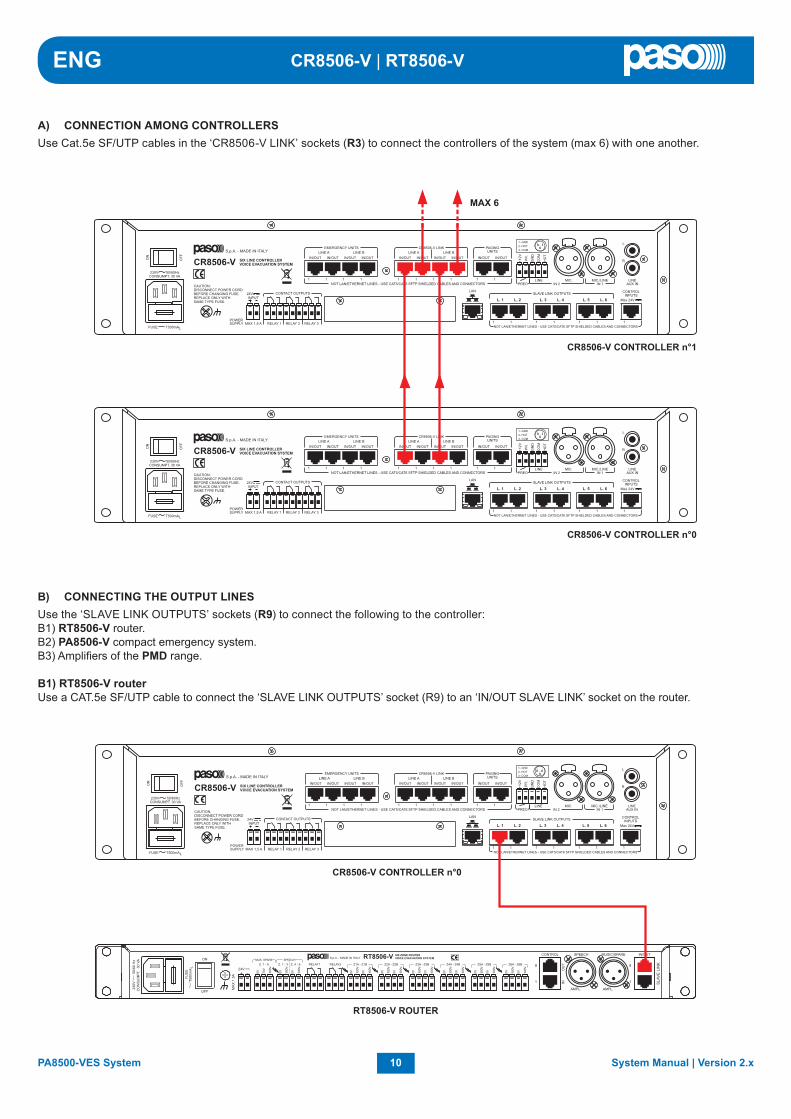
A) CONNECTION AMONG CONTROLLERSUse Cat.5e SF/UTP cables in the ‘CR8506-V LINK’ sockets (R3) to connect the controllers of the system (max 6) with one another.
B) CONNECTING THE OUTPUT LINES Use the ‘SLAVE LINK OUTPUTS’ sockets (R9) to connect the following to the controller:B1) RT8506-V router.B2) PA8506-V compact emergency system.B3) Amplifi ers of the PMD range. B1) RT8506-V routerUse a CAT.5e SF/UTP cable to connect the ‘SLAVE LINK OUTPUTS’ socket (R9) to an ‘IN/OUT SLAVE LINK’ socket on the router.
11System Manual | Version 2.x PA8500-VES System
ENGCR8506-V | RT8506-V
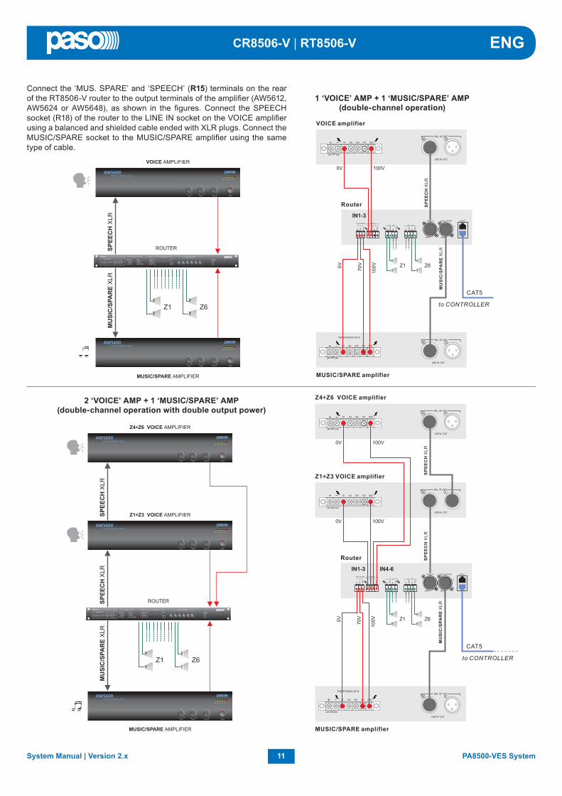
Connect the ‘MUS. SPARE’ and ‘SPEECH’ (R15) terminals on the rear of the RT8506-V router to the output terminals of the amplifi er (AW5612, AW5624 or AW5648), as shown in the fi gures. Connect the SPEECH socket (R18) of the router to the LINE IN socket on the VOICE amplifi er using a balanced and shielded cable ended with XLR plugs. Connect the MUSIC/SPARE socket to the MUSIC/SPARE amplifi er using the same type of cable.
1 ‘VOICE’ AMP + 1 ‘MUSIC/SPARE’ AMP(double-channel operation)
2 ‘VOICE’ AMP + 1 ‘MUSIC/SPARE’ AMP(double-channel operation with double output power)

12PA8500-VES System System Manual | Version 2.x
ENG CR8506-V | RT8506-V
Shared spare amplifi er (single-channel operation) In this confi guration, the spare amplifi er is shared among several routers. The music function is consequently no longer available.Each router can be connected to either one or two VOICE amplifi ers, depending on requirements. A single “master” router will be confi gured via the software. This will be the one connected directly to the. The spare amplifi er output, on the other hand, will have to be connected to the “MUS-SPARE” inputs (R15) of all the routers of the group. The controller will manage the spare amplifi er in such a way that it will only replace the fi rst failed amplifi er. Any subsequent failures will remain pending.
• Output power available in the example illustrated, with the amplifi ers indicated: Group of zones Z1 to Z6 = total 480 W Group of zones Z7 to Z9 = total 480 W Group of zones Z10 to Z12 = total 480 W Group of zones Z13 to Z18 = total 480 W
• One single emergency message at a time.

13System Manual | Version 2.x PA8500-VES System
ENGCR8506-V | RT8506-V

14PA8500-VES System System Manual | Version 2.x
ENG CR8506-V | RT8506-V
Increased router zones (double-channel operation with shared amplifi ers)In this confi guration, two or more routers are connected to the same pair of VOICE/MUSIC amplifi ers. By doing this, a single router will drive the amplifi ers. Basically, the number of zones is increased by adding more routers (and the related sets of zones) to the “basic” confi guration. • Output power available in the example
illustrated, with the amplifi ers indicated: 240 W that can be distributed over a
total of 18 zones.• Two emergency messages at the same time.

15System Manual | Version 2.x PA8500-VES System
ENGCR8506-V | RT8506-V
B2) PA8506-V compact emergency systemUse a Cat.5e SF/UTP cable to connect one of the ‘SLAVE LINK OUTPUTS’ sockets (R9) to the ‘REMOTE LINK’ socket on the PA8506-V compact system.
B3) Amplifi ers of the PMD rangeUse a Cat.5e SF/UTP cable to connect one of the ‘SLAVE LINK OUTPUTS’ sockets (R9) to the ‘IN/OUT’ socket on the amplifi er (PMD125-V, PMD250-V or PMD500-V).
On the PA8506-V, the SLAVE MODE will have to be set (CONFIGURATION menu > set> CONTR. MODE).O

16PA8500-VES System System Manual | Version 2.x
ENG CR8506-V | RT8506-V
C) CONNECTION OF EMERGENCY UNITS Use CAT. 5e SF/UTP cables to connect the ‘EMERGENCY UNITS’ sockets (R2) of the controller to the ‘IN/OUT’ sockets of the units.
C1) System with only TSB8500-V units Connect the TSB8500-V touchscreen units (max. 4 units per system) via LINE A.
C2) System only with PMB132 unitsConnect the PMB132 units (max. 7 units) via LINE A or LINE B indiscriminately.
C3) Mixed system with both TSB8500-V and PMB132 unitsConnect the TSB8500-V units via LINE A and use LINE B, on the other hand, for the PMB132 units. The total number of units connected must not exceed 7.
Important:These units have different protocols. For this reason, it is NOT possible to connect both models via the same line.
N.B.: For details concerning the connections, power supply and confi guration of the units, refer to the relevant manuals.
N.B.: In the event of a system with several controllers interconnected to one another, up to 7 units can be connected for each CR8506-V.

17System Manual | Version 2.x PA8500-VES System
ENGCR8506-V | RT8506-V
D1) Sources of BGM, “music” amplifi cation channelConnection of an example of sound sources at line or microphone level, balanced or unbalanced, selectable from the MUSIC panel and addressable to the required zones by means of the zone activation keys. For details concerning the settings, refer to the relevant sections indicated in the MUSIC and AUDIO SETTING menus.
D) CONNECTING THE AUDIO INPUTS
A - Source of music with unbalanced output at the level of the line connected to the AUX IN input. To receive, select the “AUX” BGM source from the MUSIC menu.
B - Receiver of the radio microphone kit with output balanced at the level of the microphone connected to the IN.1 input.To receive, select the “INPUT 1” BGM source from the MUSIC menu. Set the following, via the INPUT 1 panel:> MODE: OFF> PH: OFF> The Chime, Priority and Zone list parameters have no effect.
C - Mixer with output balanced at the level of the Line connected to the IN.2 LINE input.To receive, select the “INPUT 2” BGM source from the MUSIC menu. Set the following, via the INPUT 2 panel: > MODE: OFF> PH: OFF> The Chime, Priority and Zone List parameters have no effect.
Caution! Do not connect any other equipment to the MIC socket of the IN.2 input.
D2) Various types of PA source with progressive degrees of priority, “voice” amplifi cation channelConnection by way of example of one table-top microphone station, not pre-amplifi ed, with a precedence contact; of one grip-type microphone with automatic VOX activation over music; of one PABX with an audio output for automatic announcements over the sound-broadcasting system and digital stations of the PMB range for service announcements with zone selection. For details concerning the settings refer to the relevant sections indicated under AUDIO SETTING.
A - Table-top base with electret microphone, balanced output connected to the IN.1 input – MIC and precedence contact connected to the PPREC. input.The announcement will be addressed to the group of zones indicated in the ZONE LIST on the basis of the priority set. Set the via the INPUT 1 panel: >MODE: PRECEDENCE>PH: ON>Priority: 3 >Zone list: as desired>VOL.: as desiredSet the via the CHIME panel: > MIC 1: ON
B - Grip-type dynamic microphone, balanced output connected to the input IN.2– MIC with VOX function. The announcement will be addressed to the group of zones indicated on the ZONE LIST according to the priority that is set. Set the via the INPUT 2 panel: >MODE: VOX>PH: OFF>Priority: 1 >Zone list: as desired>VOL.: as desiredSet the via the CHIME panel: > MIC 2: OFF
Caution! Do not connect any other equipment to the LINE terminals of the IN.2 input.
C - Digital microphone stations connected in cascade formation to the PAGING UNIT input. The announcement will be addressed to the zones indicated when programming the keys of the bases depending on the priority set for each base.Set the PAGING UNITS panel:>VOL.: as desired (volume of the whole line for all the bases)Set the CHIME panel: > UNIT: ON

18PA8500-VES System System Manual | Version 2.x
ENG CR8506-V | RT8506-V
H) CONNECTION TO A PERSONAL COMPUTERIt is possible to connect a PC to the front-panel “TO PC” socket (C12) for downloading the confi guration fi les from the controller using the dedicated software (for details, see Section 6 – Confi guration of the system, page 26).
Sizing: For each CR8506-V unit, up to a maximum of 16 stations of the PAGING UNITS range can be connected. Use the Cat. 5 SF/UTP connecting cable, with its shielding plait. The following limits must be observed for the connections:N. 1 station connected to a line 800 metres long.N. 8 stations distributed along 2 lines, each 200 metres long (4 stations per line).
For systems calling for greater distances or a higher number of stations to be connected, it is advisable to power the stations by means of the additional power supply unit connected to the local socket of the base. The maximum length of the connecting line, adding up the lines connected to the two RJ45 sockets, is 1 km. For further details concerning the type of power supply, the confi guration of the cable, programming of the selection keys and setting of the priorities and addresses, refer to the Instruction Manual of the stations of the PMB range.
The following PAGING UNITS can be connected to the CR8506-V:• PMB106-G: 6-zone paging unit.• PMB112-G: 12-zone paging unit.
N.B.: The connections between the CR8506-V and PAGING UNITS must be made solely with CAT. 5e SF/UTP.
E) RJ45 INPUT CONTACTS (CONTROL INPUTS)There are 7 controlled contacts on the CONTROL INPUTS (R8) socket. An example of a connection is shown in the fi gure.
F) RJ45 CONTACTS (CONTROL IN/OUT)7 controlled input contacts are available on the CONTROL IN/OUT sockets of the RT8506-V router (R17) (featuring the same pin-out as the CR8506-V inputs, see previous fi gure) and 6 open collector outputs that, when activated, close to ground. The common +24VDC reference of pin no. 6 and the GND reference for connection to external peripheral units are available.Important: The maximum total absorption managed by the 6 outputs is 100 mA.
N.B.: In the example, contacts 1 to 6 are controlled while contact 7 is not.
CONTROL OUT
G) CONNECTING AN EXTERNAL POWER SUPPLYA connection for a 24 VDC outside power supply is available on the terminals provided (R12).

19System Manual | Version 2.x PA8500-VES System
ENGCR8506-V | RT8506-V
5. OPERATING CONDITIONS AND TERMINOLOGY
5.1 GENERAL DEFINITIONSFollowing is a list of the signalling modes of the operating conditions of the system and of defi nitions used in the rest of the manual, completed by indications of a general nature:
5.1.1 Signalling of operating conditionsThe CR8506-V system is structured to signal the different operating conditions on the basis of the following defi nitions:
“Quiescent condition” (ALARM – FAULT – DIS – SYS LEDs extinguished)Normal operating condition, with no current failures or emergencies. This status enables the sources of music and voice to be managed for service announcements.
“Alarm Condition” (ALARM LED illuminated)This operating condition signals the current presence of at least one alarm signal, either pre-recorded or live, on at least one output zone. The “Alarm Condition” can be activated in the form of an Automatic Emergency from an external peripheral unit connected to the Control Inputs or of a Manual Emergency through an authorised operator. During an “Alarm Condition”, the functions of the music sources and of the voice services referred to the quiescent condition are not operational.
“Fault warning condition” (Led FAULT)Operating condition signalling the presence of at least one on-going failure, detected by the internal diagnostics system causing the FAULT LED to light up steadily. In the event of failure of a remote controller, the FAULT LED will fl ash. It is accompanied by an acoustic signal (buzzer) indicating the failure. Depending on the causes of the failure, the system may in any case perform the functions relating to the “Quiescent” and “Alarm” conditions.
“System Fault” (SYS LED illuminated)This operating condition signals that the system is blocked as the result of a temporary or permanent malfunctioning of the CPU, detected by the watchdog. It is accompanied by an acoustic signal (buzzer) indicating the failure. During a System Fault, the functions relating to the “Quiescent” and “Alarm” conditions are not operational.
“Disablement condition” (DIS LED illuminated)This operating condition signals that the Alarm signals for at least one output zone have been set to a Disablement condition. The system can in any case carry on the functions pertaining to the “Quiescent” condition for all the zones and, only for those zones that are not disabled, the functions pertaining to the “Voice Alarm Condition”.
“Automatic Emergency” (CONTROL INPUT STATUS Display with zones active)This indicates a sequence of operations performed from an external peripheral unit connected to the Control Inputs. Depending on how these inputs are programmed, the “Voice Alarm Condition” or an Alarm Reset are activated.
“Manual Emergency” (LED of the EMERGENCY button ON/fl ashing)This procedure is performed by an authorised operator using the manual controls, to activate VES sources or to reset the Alarms (Manual Alarm Reset). The operations carried out in the Manual Emergency mode have a higher priority than those activated by an Automatic Emergency. A CR8506-V unit or an emergency unit on which the EMERGENCY LED is illuminated is enabled for use for activating VES sources or for resetting the alarms. A CR8506-V unit or an emergency unit on which the EMERGENCY LED is fl ashing indicates that a Manual Emergency has been activated from a remote station.
5.1.2 GlossaryFollowing is a list of defi nitions of terms used in this manual, completed by indications of a general nature.
“BGM Source”: One of the following audio sources using the “Music” amplifi cation channel (BackGround Music):- Audio source connected to the AUX input.- Flash memory device containing *.mp3 fi les plugged into to the front-panel USB EXT socket.- Audio source connected to the IN 1 input (Microphone input), set in the IN OFF mode.- Audio source connected to the IN 2 input (Microphone or Line input) set in the IN OFF mode.During a “Voice Alarm Condition”, the BGM sources are not operational.
“PA Source”: One of the following audio sources using the ”Voice” amplifi cation channel for Public Address announcements:- Source of sound connected to the IN 1 input (Microphone input), set in the ON or PRECEDENCE MODES.- Source of sound to the IN 2 input (Microphone or Line input), set in the ON, VOX or PRECEDENCE MODES.- EMERGENCY UNIT in the broadcasting mode, PAGING UNITS.During a “Voice Alarm Condition” the PA sources are not operational.

20PA8500-VES System System Manual | Version 2.x
ENG CR8506-V | RT8506-V
“VES Source”:One of the following audio sources, using the “Voice” and/or “Music” channels for emergency voice announcements (Voice Evacuation System): - Pre-recorded Alert message (ALERT).- Pre-recorded Evacuation message (EVAC).- Emergency Microphone (P.T.T.) connected to the front-panel MICROPHONE socket.- Emergency microphone station connected to the rear-panel EMERGENCY UNITS socket.Activation of a “VES source” generates an operational “Voice Alarm Condition”.
“Priority”:Use of the output zones by an audio signal or by a reset command is governed in the hierarchy by the level of priority assigned to each active source. A current activation of a zone can be interrupted only by another with a higher priority.
The CR8506-V system manages priorities as shown in the following tables:
The active sources in the “Voice Alarm” condition always have priority over those active in “Quiescent” condition, regardless of the priority level set.
Priority Systemcondition
Operatingenviroment
Prioritylevel
Activesource
For setting seeMENU
high
low
“Voice alarmcondition”
ManualEmergency
15 CR8506-V with emergency microphone Fixed setting
8 to 14 Emergency microphone stations See the manuasl of PMB132 range & TSB8500-V
AutomaticEmergency
7 CONTROL INPUT for RESET function Fixed setting
6 CONTROL INPUT for EVAC message Fixed setting
5 CONTROL INPUT for ALERT message Fixed setting
high
low
“Quiescentcondition”
PASource
8 to 14 Emergency units in broadcast mode See Emergency units manual
1 to 7
Inputs IN 1 - IN 2 with the PRECEDENCE or VOX functions See AUDIO SETTING section
PAGING UNITS Microphone stations See the manual of PMB106-G & PMB112-G
BGMSource 0 Music source Fixed setting

21System Manual | Version 2.x PA8500-VES System
ENGCR8506-V | RT8506-V
5.2 EQUIPMENT AND FUNCTIONAL SPECIFICATIONS
5.2.1 CR8506-V controller
Front panelF1. Emergency button with LED (red) Flush-mounted push-button for activating the Manual Emergency mode. It enables access to the system, with top priority, from the
“Quiescent condition” or during an Automatic Emergency, previously activated from an external peripheral unit. The LED, which is normally extinguished, will light up steadily in the Manual Emergency mode activated from the unit in question. If the LED fl ashes, this indicates a Manual Emergency status activated from an emergency microphone station or a remote controller. The Emergency button will also be used for exiting the Manual Emergency. The push-button is controlled by the internal diagnostics system.
F2. Emergency microphone Hand-held microphone with Push-to-Talk (P.T.T.) key, for live emergency announcements. The microphone is only operational in Manual
Emergency conditions and has priority over pre-recorded emergency messages. The microphone capsule is controlled by the internal diagnostic system. Use only the microphone included in the supply, connected directly, without any extension cable, to the XLR socket on the front panel of the CR8506-V.
F3. Graphic DISPLAY Backlit black-and-white graphic display, 128x64 pixels, for displaying the many management windows, the contents of which will vary
depending on the operating conditions of the system (quiescent or emergency). Together with the +/- knob and with the multi-purpose keys, it is useful for navigating through the menus, for adjusting working parameters and for managing advanced functions. It will also display all the information required concerning Fault, Disablement and Voice Alarm Conditions, that are not all signalled by the status LED’s.
Rear panelR1. POWER switch ON/OFF switch of the CR8506-V system. In the O (OFF) position, the system is switched off and in the I (ON) position the system is switched
on. The switch affects only the main 230 VAC power supply (see the “Power Supply and Earthing” and “Safety Notes” sections for details about safety).
R2. EMERGENCY UNITSInput for connecting remote emergency microphone stations. Use only the PASO PMB132-V, PMB132/12-V and/or TSB8500-V microphone stations. RJ45 socket for connection with Cat. 5e SF/UTP cable with a shielding braid and shielded STP connector (for connection details, refer to the manuals of the units, PASO codes 11/716 and 11/788 respectively). The EMERGENCY UNITS must be connected to one another in daisy-chain fashion: each of the two connecting lines A and B can reach a total length of up to 1 km.
R3. CR8506-V LINK Sockets for connections among CR8506-V controllers (up to 6) Connectors for connections among several controllers. If both LINK A and LINK B are used, a redundant connection is achieved that keeps
the system in working order even if one of the two links fails. If more than one controller is installed on the same rack, it is possible to use a single LINK (A or B). if this is done, it is necessary to de-activate the remote link test not being used:
o Path: HOME / CONFIGURATION / set> BACKGROUND TEST / 2-Voice Alarms / 6-Remote Link > Link Test

22PA8500-VES System System Manual | Version 2.x
ENG CR8506-V | RT8506-V
R4. PAGING UNITS Input for connecting paging microphone stations (PMB106-G, PMB112-G) for broadcasting functions. It is possible to connect up to a total
of 16 Paging Units. RJ45 sockets (2 off) for connection with Cat. 5e SF/UTP cable with shielding braiding and shielded STP connector. The connection with the Paging Units must be of the daisy-chain type. The two connecting lines can reach a total length between them of up to 1 km.
R5. IN. 2 – MIC. / LINE and PRECEDENCE TERMINAL STRIP INPUT 2 is a balanced input for a microphone or an external source, programmable as a Music or Voice source. Use the MIC input to connect
dynamic or electret microphones, enabling the phantom power supply or, as an alternative, the input on the terminal strip for sources at line level such as mixers or pre-amplifi ed microphone stations. The input can be set in many different ways, depending on how the operating mode is programmed:
- as a Voice source enabled by the precedence contact (PREC.), with a CHIME that can be activated/de-activated. - as a voice source for automatic VOX activation with adjustment of the activation threshold and of the release time and the possibility of
an activatable/de-activatable CHIME. When used as a voice source, the priority can be set with 7 different levels, and the group of paging zones can be selected. Do not use simultaneously the MIC. and LINE inputs of the IN. 2 input but: - the XLR F socket for connecting a balanced signal of up to 100 mV, or - the socket with 3 terminals, HOT-COM-GND, for stripped wire, for connection of a balanced signal of up to 1.8 V. In both cases, use shielded balanced microphone cable. For details concerning the settings of the IN. 2 input, refer to the information
shown in the Music menu and under AUDIO SETTINGS > INPUT 2 and CHIME. PRECEDENCE TERMINAL STRIPTerminal strip for connecting the precedence contact to the current music source, for activation of the IN. 1 or IN. 2 inputs and of the CHIME, if enabled. The precedence function can be used in either of the 3 following ways. The precedence function can be used with MIC 1 or MIC 2 if it is enabled on their control panels. For details of the precedence settings, refer to the indications shown on the INPUT 1 and INPUT 2 panels and in the AUDIO SETTING menu. Activation is carried out keeping the +12 V terminal connected to the PR. terminal, by closing a dry contact or connecting the available precedence contact to PASO table-top microphones of the B701, B711 or B53 ranges.
R6. IN. 1 – MIC 1 INPUT 1 input for an external microphone, programmable as a Music or Voice source. It is possible to connect dynamic or electret
microphones to this input, enabling the phantom power supply. Programming of the operating mode enables use as a voice source enabled by a precedence contact (PREC.), with the possibility of activating/de-activating a CHIME.
When it is used as a Voice source, it is possible to set priority, to 7 different levels, and the group of paging zones. The XLR -F socket enables a balanced signal of up to 100 mV to be connected, by means of shielded balanced microphone cable. For details concerning the settings of the IN. 1 input, refer to the indications contained in the INPUT 1 panel (point 8.3.4).
R7. LINE AUX IN Input for connecting an external source of music. It has one pair of RCA sockets, with conversion to mono, for sources with unbalanced
outputs at line level. For the audio settings of the AUX input, refer to the information contained in the MUSIC menu.
R8. CONTROL INPUTS 7 digital inputs for monitoring via external peripheral units. They enable programmed events to be activated, including switching of the
CR8506-V system to a Voice Emergency condition, requiring automatic sending of pre-recorded emergency messages. Activation is possible by means of Normally Open or Normally Closed contacts, relaying the +24 VDC voltage supplied from the service sockets. It is possible to enable diagnostics of the connecting stretch, arranging to install two 10-kOhm balancing resistors in the proximity of the contact for activating the remote peripheral unit (see diagram on page 18).
R9. SLAVE LINK OUTPUTS 6 output lines for connection to PMD amplifi ers and/or PA8506-V compact emergency systems and/or RT8506-V routers.
R10. LAN Socket for connecting an Ethernet 10/100 Local Area Network using the TCP/IP protocol.
R11. RELAY 1 – RELAY 2 – RELAY 3 3 relay outputs for signalling to external peripheral units. The CR8506-V system enables the logical outputs to be programmed to link
activation of the output with system status events or for override functions in connection with emergency conditions, or for signalling failures, emergencies and disabling. All the outputs can be programmed to be either Normally Active or Normally De-activated. The connection calls for 3 screw-down terminals for stripped wires for each relay, referred to N.O. and N.C. contacts - Changeover.N.B.: Two outputs are available on the RT8506-V router.
R12. Terminals for external 24 VDC power supply Terminals for connecting the auxiliary 24 VDC power supply. This is not used when the 230 VAC mains power supply is available. The input
is protected against inversion of the poles. Consult the “Power supply and earthing” and “Safety Notes” sections for details about safety.. N.B.: The batteries and the battery-charger must be installed on the same rack on which the CR8506-V controller is mounted.
R13. Frame connection The frame connection may be used to connect other equipment only for the purpose of shielding the low signals. This terminal may not
be used to connect the frame to earth for safety purposes. (Consult the “Power supply and earthing” and “Safety Notes” sections for details about safety).
R14. Plug for 230 VAC mains power with built-in fuse Plug for connecting the equipment to the 230 VAC/50-60Hz mains power using the power cable supplied with it. If it is necessary to
replace the mains fuse, this must be done with one of the same type, i.e. 500 mA fuse, of the miniature 20 mm cylindrical type. (consult the “Power supply and earthing” and “Safety Notes” sections on page 8 for details about safety).
23System Manual | Version 2.x PA8500-VES System
ENGCR8506-V | RT8506-V
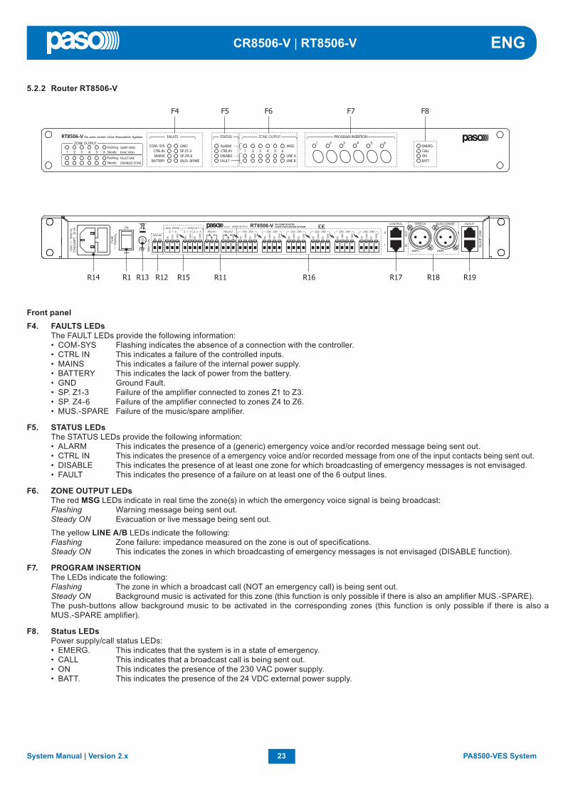
5.2.2 Router RT8506-V
Front panelF4. FAULTS LEDs The FAULT LEDs provide the following information: • COM-SYS Flashing indicates the absence of a connection with the controller. • CTRL IN This indicates a failure of the controlled inputs. • MAINS This indicates a failure of the internal power supply. • BATTERY This indicates the lack of power from the battery. • GND Ground Fault. • SP. Z1-3 Failure of the amplifi er connected to zones Z1 to Z3. • SP. Z4-6 Failure of the amplifi er connected to zones Z4 to Z6. • MUS.-SPARE Failure of the music/spare amplifi er.
F5. STATUS LEDs The STATUS LEDs provide the following information: • ALARM This indicates the presence of a (generic) emergency voice and/or recorded message being sent out. • CTRL IN This indicates the presence of a emergency voice and/or recorded message from one of the input contacts being sent out. • DISABLE This indicates the presence of at least one zone for which broadcasting of emergency messages is not envisaged. • FAULT This indicates the presence of a failure on at least one of the 6 output lines.
F6. ZONE OUTPUT LEDs The red MSG LEDs indicate in real time the zone(s) in which the emergency voice signal is being broadcast: Flashing Warning message being sent out. Steady ON Evacuation or live message being sent out.
The yellow LINE A/B LEDs indicate the following: Flashing Zone failure: impedance measured on the zone is out of specifi cations. Steady ON This indicates the zones in which broadcasting of emergency messages is not envisaged (DISABLE function).
F7. PROGRAM INSERTION The LEDs indicate the following: Flashing The zone in which a broadcast call (NOT an emergency call) is being sent out. Steady ON Background music is activated for this zone (this function is only possible if there is also an amplifi er MUS.-SPARE). The push-buttons allow background music to be activated in the corresponding zones (this function is only possible if there is also a MUS.-SPARE amplifi er).
F8. Status LEDs Power supply/call status LEDs: • EMERG. This indicates that the system is in a state of emergency. • CALL This indicates that a broadcast call is being sent out. • ON This indicates the presence of the 230 VAC power supply. • BATT. This indicates the presence of the 24 VDC external power supply.

24PA8500-VES System System Manual | Version 2.x
ENG CR8506-V | RT8506-V
5.2.3 Controller control panel
Rear panelR1. POWER switch See page 21.
R11. RELAY 1 – RELAY 2 2 relay outputs for signalling to external peripheral units (see page 22).
R12. Terminals for external 24 VDC power supply See page 22.
R13. Frame connection See page 22.
R14. Plug for 230 VAC mains power with built-in fuse See page 22.
R15. MUSIC SPARE / SPEECH terminals Terminal block for connection to the outputs of the voice and music/spare amplifi ers. It is possible to set four different connection
confi gurations.
R16. Terminals Z1A/B to Z6A/B Power outputs for lines to speaker units. Use only speaker units with 100-V constant-voltage line repeating coils. Six output zones are
available and each zone is split up into two lines, A and B, to create a loudspeaker network featuring double redundant lines. In the event of a short-circuit on one line, the RT8506-V will de-activate the output for the failed line and will continue to power the other line of the same zone, activating a Failure signal. 12 pairs of screw-down terminals for wires having cross-sections of up to 2.5 mm2 are available for connecting the 0V-100V lines.
R17. CONTROL sockets • 7 monitored digital inputs for control via external peripheral units. These enable activation of programmable events, in Voice Emergency
conditions, requiring pre-recorded emergency messages to be sent out automatically. Activation is possible via Normally Open or Normally Closed contacts, relaying the +24 VDC power supplied via the CONTROL socket. It is possible to enable diagnostics for the connecting line by installing two 10-kOhm balancing resistors in the proximity of the contact for activating the remote peripheral unit. This connection calls for a RJ45 socket with Cat. 5e SF/UTP cable (refer to the diagram on page 18).
• 6 open-collector outputs for driving generic external or peripheral relays. The PA8500-VES system enables the logical outputs to be programmed to link activation of the output with system status events or for override functions in emergency conditions or for signalling failures relating to the current emergency and to the disablement. These outputs can be programmed as Normally Open or Normally Closed and they have internal 24 VDC voltage with automatically resetting protection devices. This connection calls for a RJ45 socket with Cat. 5e SF/UTP cable.
R18. SPEECH and MUSIC/SPARE microphone sockets
• SPEECH Connection to the voice amplifi er(s). • MUSIC/SPARE Connection to the music/spare amplifi er.
R19. SLAVE LINK IN/OUT sockets Input/output for connection to the corresponding socket L1÷L6 on the CR8506-V controller (RJ45 socket with Cat. 5e SF/UTP cable).
C1. Monitoring/beep loudspeaker Built-in loudspeaker for signalling detection of failures (beep). The signalling tone will be automatically muted if the failure conditions cease
to exist. Furthermore, in order to avoid triggering acoustic feedback, it will be muted by the system while the Emergency Microphone is being used.
C2. RESET button Key for resetting the pre-recorded emergency messages manually, operational during Manual Emergencies. Key for resetting the buzzer
and for cancelling signalling of the failure, operational when there is a failure present or after a failure has been cleared. In the idle condition, this key is not operational.

25System Manual | Version 2.x PA8500-VES System
ENGCR8506-V | RT8506-V
C3. ALERT button Key for sending pre-recorded Alert messages manually, operation during Manual Emergencies. In the idle condition this key is not
operational.
C4. EVAC button Key for sending pre-recorded Evacuation messages manually, operational during Manual Emergencies. In the idle condition this key is
not operational.
C5. MENU key Multi-purpose key for accessing the Main Page, for navigating among the menus and for specifi c functions of the submenus indicated
on the displays.
C6. OK key Multi-purpose key for confi rming selections, for navigating among the menus and for specifi c functions of the submenus indicated on the
displays.
C7. ESC key Multi-purpose key for returning to the Music menu, for navigating among the menus and for specifi c functions of the submenus indicated
on the displays.
C8. Numerical keys from 1 to 6 Multipurpose keys, operational throughout the system. These keys are used to select the zones, from 1 to 6. For the CR8506-V unit being
used. They enable the access password to be entered or the specifi c functions indicated on the status bar on the display to be applied.
C9. Status signalling • ALARM LED (red) LED for signalling the existence of a “Voice Alarm Condition”. A VOICE ALARM condition can be activated both automatically from an
external peripheral unit, and manually by the operator of the CR8506-V or of an emergency microphone station. During the VOICE ALARM condition, the standard functions for playing out music and the voice source service are disabled. In the “Quiescent condition” the ALARM LED is extinguished.
• FAULT LED (yellow) LED for signalling the existence of a “Fault condition”. This indicates that the diagnostic system has detected at least one failure in the
CR8506-V unit or in one of the items of equipment connected to it and covered by the diagnostic procedure. When the fault condition is cleared, the FAULT LED extinguishes automatically and the wording “RES” is shown on the FAULTS display, to show that a failure has been detected and subsequently remedied (RESUMED). The LED signalling that the fault has been cleared will extinguish once the MANUAL FAULT RESET procedure has been completed. The FAULT signalling can be active during the standard functions of music and voice reproduction (Quiescent Condition) and Emergency (Alarm Condition).
• DIS. LED (yellow) LED for signalling activation of the disablement of the emergency zones (DISABLING). The DISABLING signal indicates that at least one
zone has been disabled by the emergency envisaged when confi guring the system. Activation of the DISABLING signal does not prevent normal operation of the system in a “Quiescent Condition”.
• SYS LED (yellow) LED for signalling an existing “System Fault” (System CPU Fault) condition. When the SYS LED is illuminated, all the operational functions,
whether of the standard or emergency type, are disabled.
• BATT. LED (green) This LED refers to the 24 VDC auxiliary power supply. The BATT. LED lights up to indicate that the 24 VDC power supply is connected
to the system.
• ON LED (green) This LED signals that the CR8506-V system is switched on and operational. The ON LED continues to be illuminated when: - 230 VAC power supply present and POWER switch in the ON position. The ON LED will fl ash continuously when: - there is no 230 VAC power supply but the 24 VDC power supply is available. The ON LED will be Off in the following cases: - no 230 VAC and no 24VDC power supply, or - 230 VAC power supply in order, no 24 VDC power supply and POWER switch in the OFF position.
C10. +/- knob This is a rotary control with no end-of-travel. It is a multi-purpose control that depends on the specifi c menu that is operational. It is used
to move the cursor to select and adjust values. In an idle condition, in the Music menu it is used to control directly the master output volume of the BGM.
C11. “EXT.” USB socket Powered type A USB socket for connecting external fl ash memories.
C12. “TO PC” USB socket Type B USB socket for connecting the management PC to be used with the dedicated system software.

26PA8500-VES System System Manual | Version 2.x
ENG CR8506-V | RT8506-V
6. CONFIGURATION OF THE SYSTEM
6.1 INTRODUCTIONThe PA8500-VES confi gurator 2.x software enables the whole system you wish to create to be compiled and confi gured. To install the programme, click twice on the “pa8500-setup.exe” fi le.
N.B.: In order for the programme to work correctly, the operating system of the PC must be Windows 7® or higher.
6.2 CREATING A NEW PROJECT FILEOnce you have started the programme. You can already create a new system confi guration. To create the new fi le, select File > New Project on the menu bar.To add a description to the project, select Project > Edit Description and enter it in the fi eld provided (max 22 digits).To save the new project, select File > Save Project As: use the dialogue box to assign a name to the project and identify or create a destination folder. The status bar at the bottom of the window will show that the operation has been completed successfully.
Once this has been done, you can start to confi gure the system.To save an open project simply select File > Save Project*.
6.3 OPENING AN EXISTING PROJECTTo open a previously saved project, select File > Open Project; in the dialogue box, select the folder and the desired *.prg fi le.
* It is possible at any time to compile a new project by selecting File > New Project. Of course all the previously entered data will be lost since the programme will start again from an empty project.

27System Manual | Version 2.x PA8500-VES System
ENGCR8506-V | RT8506-V
• RT8506-V - routerIf you select this item, the Line 1 confi guration window will open, in which you can select the features of the zones and the input and output contacts of the router. You can also indicate the presence of amplifi ers connected to it. Once you have set the parameters, press End (or Cancel to exit without saving the changes made). With version 2.x, it is possible to select the new On transition parameter, which enables to set transition or status inputs (if messages are involved). By means of inputs, it is also possible to arrange for an Evacuation message (Evac input) and/or an Alert message (Alert input) to be sent out to two separate sets of zones (single zone, ALL or confi gurations). The Override event has also been introduced upon activation of the output contacts. It closes the contact (according to positive logic) in the event of a broadcasting call to a set of zones defi ned during confi guration.
6.4 INSERTING THE CONTROLLERSFrom the Tools menu, select Tools > Insert Controller and add the number of CR8506-V units in the system (in the example, there are two of them).The controller with the address “0” is factory-set as the “Master”, and there must be one in each project.
6.5 CONFIGURING THE CONTROLLERNow confi gure the single lines for each controller, starting from the Master and setting the parameters for line 1.Press LINE 1 > Confi gure: A window will open in which you can select the equipment that is connected to this line (none, RT8506-V router, PMD amplifi ers or a PA8506-V compact system).
Select the required option and click on Continue >.Each option leads to a specifi c dedicated window, except for “NONE”, which returns the line to an unused condition.
You can fi nd a brief summary of the settings made by clicking on LINE 1 > Report.

28PA8500-VES System System Manual | Version 2.x
ENG CR8506-V | RT8506-V
• PMD amplifi ers
IMPORTANT NOTICE!All the amplifi ers connected to a line must necessarily have progressive addresses, from number 1 onwards (max 16 for each line). To set the address of each single amplifi er, consult the “Settings” section in the instruction booklet of the PMD range (PASO code number 11/733).
Supposing you wish to set line 2 for connection to amplifi ers of the PMD range: after pressing LINE 2 > Confi gure and selecting PMD - amplifi ers the Line 2 confi guration window will open.
In this window it is possible to list the amplifi ers (and their models) connected to the lines in question, in addition to indicating whether they are stand-by amplifi ers. The associations between the various different amplifi ers and the standby units as selected under the heading “Confi guring the standby amplifi ers” (Page 27) are also highlighted. The programme will guide you through the procedure in order to ensure that several rules are followed:- The entries are sequential, starting from address 1. If an amplifi er half-way down the list is deleted by selecting model = “none” as the model,
therefore, all the amplifi ers with the next addresses will also be removed.- One line can manage up to a maximum of two standby units. The fi rst of these is “global”, that is to say it can replace the amplifi ers of any other
line of the controller. The second standby unit can be either: • “global” if there are only two standby units on the lines; or • “local” if there are additional amplifi ers on the line. In this case, the standby unit can only replace amplifi ers belonging to the same line as
the unit itself.The programme carries out cross-checks to ensure that the compilation is correct.Once you have completed the compilation, press End to save the confi guration, which will appear associated with line 2 in the main window. As an alternative, you may press Cancel to exit without saving the changes made.
• PA8506-V compact systemFor line 3, set a connection to a PA8506-V compact system: after pressing LINE 3 > Confi gure and selecting the item PA8506-V - compact the Line 3 confi guration window will open.
Once you have set the parameters for all the lines, go on to compile the other four connections shown in the main window: CTR INPUT, CTR OUTPUT, EMERGENCY UNITS and BROADCASTING UNITS.

29System Manual | Version 2.x PA8500-VES System
ENGCR8506-V | RT8506-V
• CTR INPUTPress CTR INPUT > Confi gure. The Controller 0 input confi guration window will open, in which you can associate the required parameters with each of the 7 contacts.
Press End to save the confi guration, or press Canc. to cancel it and return to the main window.
N.B.:With this new version it is possible, by means of the inputs, to send out the evacuation message (Evac input) and/or the alert message (Alert input) to two separate sets of zones (single zone, ALL or confi gurations).
• EMERGENCY UNITSPress EMERGENCY UNITS > Confi gure. The window for confi guring the emergency stations that can be connected will open.
On selecting the units, the software automatically shows the correct combination with the line to be used (see the section on Connection of emergency units on page 16). To set a specifi c confi guration for the keys associated with each emergency station, press the relevant Key Conf.: It is possible to call up a confi guration that has already been defi ned (see “Confi guring groups of zones”) or to make changes manually to the default confi guration prompted in the ‘Unit key list’ box.
N.B.:For the TSB8500-V units, on the other hand, the Key Conf. key is disabled as confi guration of these units has to be carried out directly on the units by means of the touch screen display.
Press End to save the confi guration, or press Canc. to cancel it and return to the main window.
• CTR OUTPUTPress CTR OUTPUT > Confi gure. The Controller 0 output confi guration window will open, in which – as already seen for the inputs – you can associate the required parameters with each of the 3 contacts.
Press End to save the confi guration, or press Canc. to cancel it and return to the main window.

30PA8500-VES System System Manual | Version 2.x
ENG CR8506-V | RT8506-V
Premere End per salvare la confi gurazione, oppure Canc. per annullarla e ritornare alla schermata principale.
• PAGING UNITSPress PAGING UNITS > Confi gure. The broadcasting call station confi guration window will open.To set a specifi c confi guration for the keys associated with each emergency station, press the relevant Key Conf: It is possible to call up a confi guration that has already been defi ned (see “Confi guring groups of zones”) or to make changes manually to the default confi guration prompted in the ‘Unit key list’ box. To do this, from the list on the right-hand side, select the key for which you wish to change the setting. From the list on the left-hand side, select the zone or the confi guration you wish to associate with it, then click on the central arrows. The new combination selected by you will appear immediately on the list on the right-hand side.
Press End to save the confi guration, or press Canc. to cancel it and return to the main window.
• Confi guring groups of zonesFrom the menu, select View > Key confi guration to open a complete schedule of the zones referred to the controllers installed in the system. Against a white background, the window will show the number of units and zones that have been set. For each controller, the active zones are shown in red. The status of each zone can be altered simply by clicking on the number, which will turn green. After setting the zones you require, click on Save to save the confi guration. To create the next confi guration fi le, select the name in the drop-down menu as before. In this window, you can set up to 64 confi guration fi les, which you can call up in the confi guration windows of the stations (see previous sections).
31System Manual | Version 2.x PA8500-VES System
ENGCR8506-V | RT8506-V
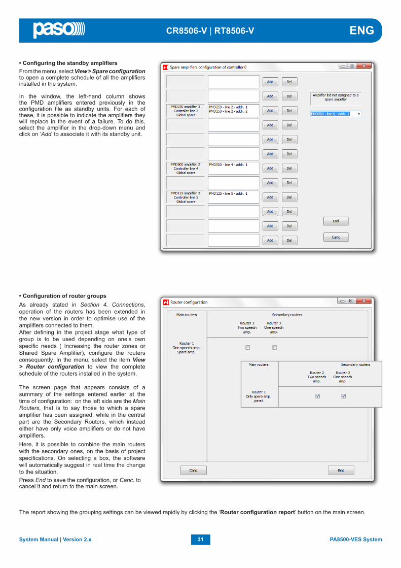
• Confi guration of router groupsAs already stated in Section 4. Connections, operation of the routers has been extended in the new version in order to optimise use of the amplifi ers connected to them.After defi ning in the project stage what type of group is to be used depending on one’s own specifi c needs ( Increasing the router zones or Shared Spare Amplifi er), confi gure the routers consequently. In the menu, select the item View > Router confi guration to view the complete schedule of the routers installed in the system.
The screen page that appears consists of a summary of the settings entered earlier at the time of confi guration: on the left side are the Main Routers, that is to say those to which a spare amplifi er has been assigned, while in the central part are the Secondary Routers, which instead either have only voice amplifi ers or do not have amplifi ers.Here, it is possible to combine the main routers with the secondary ones, on the basis of project specifi cations. On selecting a box, the software will automatically suggest in real time the change to the situation.Press End to save the confi guration, or Canc. to cancel it and return to the main screen.
The report showing the grouping settings can be viewed rapidly by clicking the ‘Router confi guration report’ button on the main screen.
• Confi guring the standby amplifi ersFrom the menu, select View > Spare confi guration to open a complete schedule of all the amplifi ers installed in the system.
In the window, the left-hand column shows the PMD amplifi ers entered previously in the confi guration fi le as standby units. For each of these, it is possible to indicate the amplifi ers they will replace in the event of a failure. To do this, select the amplifi er in the drop-down menu and click on ‘Add’ to associate it with its standby unit.

32PA8500-VES System System Manual | Version 2.x
ENG CR8506-V | RT8506-V
At this point, the main window of the programme will show most of the settings made.
It is possible to obtain a complete printable report of all the settings simply by clicking on ‘Ctr confi guration report’, ‘Zone confi guration report’ and ‘Spare confi guration report’ and ‘Router confi guration report’.
Once you have loaded the fi le, you can indicate whether it is a message to be sent in warning situations (Alert) or in evacuation situations (Evac).It is also possible to add a brief description of each message entered (max 25 digits).
In addition to voice messages, a warning tone (Chime) can also be entered, using the same procedure.
Press End to save the confi guration, or press Canc. to cancel it and return to the main window.
• Compiling voice messages / warning signalsFrom the menu, select View > Message Compiler to open the window enabling management of the pre-recorded voice messages and of the warning signal, if any. Click on Path > Add fi le and load the required *.wav fi le.
N.B.. The fi les to be used must necessarily be recorded in and /or converted into the *.WAV 48 ksample 16bit audio format.
Once you have completed confi guring CONTROLLER 0, save the project and click on the “CONTROLLER 1” tab to proceed with its confi guration.

33System Manual | Version 2.x PA8500-VES System
ENGCR8506-V | RT8506-V
• Creation of an SD cardThis procedure requires the SD card to be removed from the controller and the PC card reader to be used. After making sure that the controller is switched off, use a screwdriver to unscrew the small cover at the centre of the rear panel and remove it.
Once all the confi guration operations have been completed, it is necessary to enter all the information in each SD card of the CR8506-V units. As many SDs as there are controllers in the system will have to be created. Each card will contain the information referred both to the specifi c controller concerned and to the rest of the system.As an alternative to the procedure described above – writing on the SDs via the PC – it is possible to use the USB connection, leaving the card inserted into the controller.
Insert the SD into the drive of the PC, then select the CONTROLLER 0 window. From the main menu, select Tools > Create SD. The card will be formatted and then automatically programmed with the necessary data. Once writing has been completed, remove the SD card from the PC, then plug it into its slot in the rear panel of CONTROLLER 0. Put the cover back into place and fi x it with the screws removed earlier.
Repeat these operations for all the other controllers (in the example, CONTROLLER 1).
C) Load the confi guration fi les entered in the controller (and any messages) into the PC. These fi les will be saved in a dedicated folder. You will be able to open this folder later from the File > Load from upload from the opening page of the software. To achieve complete confi guration of the system, simply load the confi guration from a single controller plus the messages from all the controllers connected.
Note: When the confi guration is loaded, it is advisable to delete the upload area if requested by the software.
B) To download the confi guration fi les and/or messages from the PC to the controller (this function is only enabled if a project has been opened and saved). If this operation is used to up-date the confi guration of a controller, it is advisable to repeat the same procedure also for all the remaining controllers of the system, using the “Complete confi guration” option.
• Connection to a PC via USBIt is possible to connect the controller to a PC so as to upload and/or download confi guration fi les and messages from/to the equipment. The PC must have a Windows Vista®, Windows 7® or higher operating system and a USB 2.0 port. To make this connection, it is necessary to proceed as follows:
N.B.:Following integration of the new system functions, the structure of the confi guration has been changed and the data on the SD cards are no longer compatible with the previous systems. It should therefore be noted that:• version 1.x controllers must use only SD cards produced with version 1.x software;• the current version of controllers (2.x) will use only SD cards produced with 2.x software.However it is possible to connect controllers of different versions with each other provided each of them complies with the rule indicated above.
1) First of all, before making the connection to the controller, install the software on the PC;2) Plug a USB/MiniUSB cable into the front-panel “TO PC” socket of the controller (C12);3) Plug the other end of the cable into one of the USB 2.0 sockets on the PC;4) Wait for the operating system to load the driver of the device. The Virtual Com Port icon (in the example, this is COM10) will appear in the
“Devices and printers” section of the control panel;5) From the menu, select Tools > USB connection; you will be asked to indicate the communications port to be used (in our example, select
COM10);6) In the box, enter the confi guration password that is active on the controller (3333, which is the factory setting) and press OK.
The controller and the PC are now able to communicate with one another. The PA8500-VES Usb connection page will open, and from here it will be possible to proceed as follows:A) To change the address of the controller: enter the new address (from 0 to 5) and press “Change”.

34PA8500-VES System System Manual | Version 2.x
ENG CR8506-V | RT8506-V
7. MENU STRUCTURE
The CR8506-V enables access to the system functions through a set of Management Panels, grouped according to operational typologies and intended uses into Option Menus accessible from the Main Page. Furthermore, the following Option Menus were assigned to different levels of access, with reference to the various different circumstances requiring different degrees of skill on the part of the personnel and different levels of authorisation.
• < MUSIC > MenuDefault window for using the system in normal Quiescent Conditions. It enables control of the BGM sources and adjustment of the volumes of the music section. This menu is not accessible during a Voice Alarm Condition. At this basic level, the RESET, ALERT and EVAC keys are not operational.
• < AUDIO SETTING > MenuGroup of basic options for standard operating conditions. It is intended for users for setting and adjusting the PA sources. At this basic level, the RESET, ALERT and EVAC keys are not operational.
• < INSPECTION > Menu First access level, for investigating the status of the system. It is intended for the personnel responsible for initial checking of the causes leading to a failure or emergency condition. At this initial access level, the RESET key has the function of resetting the buzzer signalling a FAULT. At this basic level, the ALERT and EVAC keys are not operational.
• < OPERATOR > MenuSecond access level for trained personnel, authorised to manage the system in emergency, failure and disablement conditions. A password for accessing this level can be added.
• < CONFIGURATION > MenuThird access level, for trained personnel authorised to use the advanced functions of the system and to alter the confi guration parameters, for starting up and altering the system. A password for accessing this level can be added.
• < SERVICE > MenuFourth access level, included among the options of the CONFIGURATION Menu, for servicing activities, up-dating of fi rmware and altering the operating parameters of the CR8506-V controller. Use is permitted only for technical personnel having the necessary access key.
• < EMERGENCY > MenuOperational environment for managing Manual Emergencies, with top priority. Accessible at all times using the dedicated “Emergency” key, it may be used only by authorised personnel trained with regard to the Emergency and Evacuation Plan (EEP).
The functions associated with levels featuring restricted access, for which a password may be set, are highlighted by the symbol
7.1 “HOME” FUNCTIONS - ACCESS TO THE OPTION MENUS7.1.1 Basic Level - MUSIC menuAfter switching on the system, the MUSIC Management Window will be shown directly. To access the HOME page, press the MENU key. From the HOME page it will be possible to select the various different Option Menus for the advanced functions of the system. From the HOME page, press ESC to return to the MUSIC management panel.
MENU
ESC
35System Manual | Version 2.x PA8500-VES System
ENGCR8506-V | RT8506-V
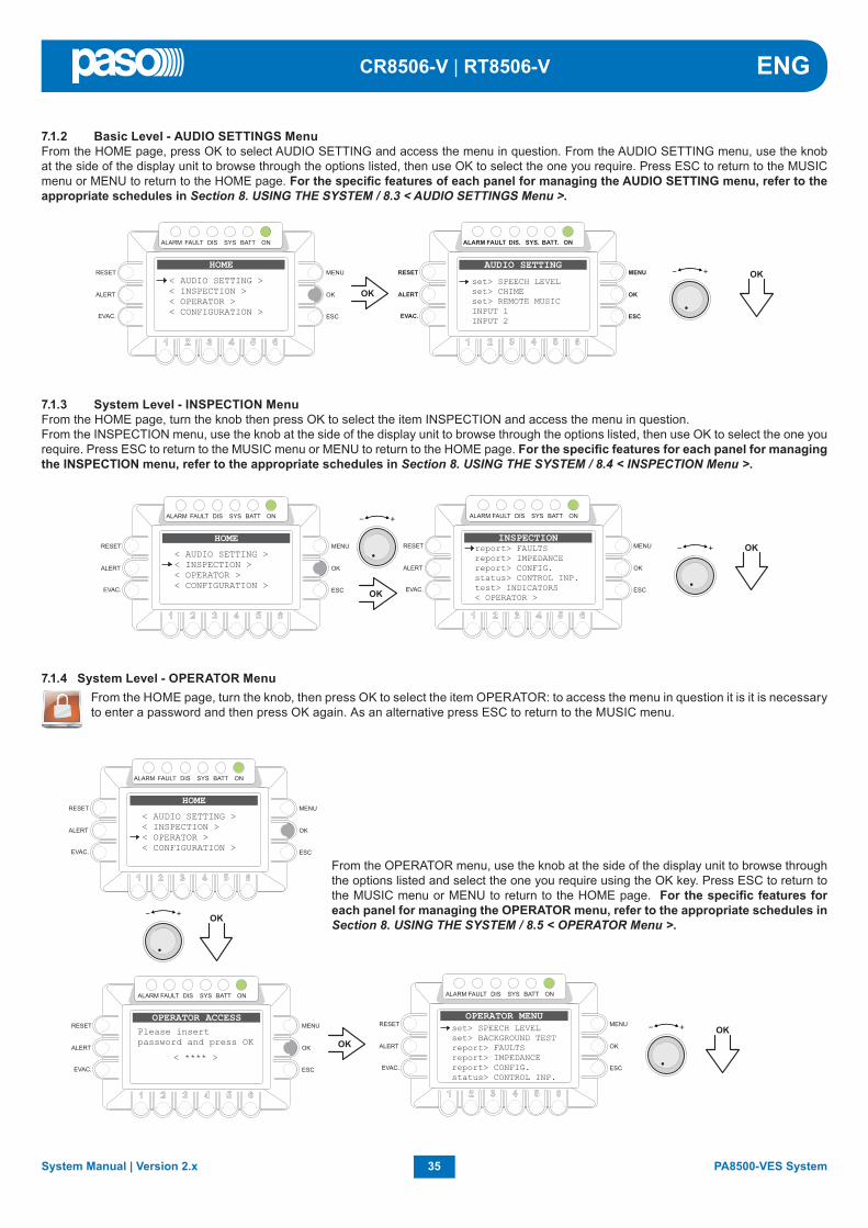
7.1.2 Basic Level - AUDIO SETTINGS MenuFrom the HOME page, press OK to select AUDIO SETTING and access the menu in question. From the AUDIO SETTING menu, use the knob at the side of the display unit to browse through the options listed, then use OK to select the one you require. Press ESC to return to the MUSIC menu or MENU to return to the HOME page. For the specifi c features of each panel for managing the AUDIO SETTING menu, refer to the appropriate schedules in Section 8. USING THE SYSTEM / 8.3 < AUDIO SETTINGS Menu >.
7.1.3 System Level - INSPECTION MenuFrom the HOME page, turn the knob then press OK to select the item INSPECTION and access the menu in question.From the INSPECTION menu, use the knob at the side of the display unit to browse through the options listed, then use OK to select the one you require. Press ESC to return to the MUSIC menu or MENU to return to the HOME page. For the specifi c features for each panel for managing the INSPECTION menu, refer to the appropriate schedules in Section 8. USING THE SYSTEM / 8.4 < INSPECTION Menu >.
7.1.4 System Level - OPERATOR Menu From the HOME page, turn the knob, then press OK to select the item OPERATOR: to access the menu in question it is it is necessary
to enter a password and then press OK again. As an alternative press ESC to return to the MUSIC menu.
From the OPERATOR menu, use the knob at the side of the display unit to browse through the options listed and select the one you require using the OK key. Press ESC to return to the MUSIC menu or MENU to return to the HOME page. For the specifi c features for each panel for managing the OPERATOR menu, refer to the appropriate schedules in Section 8. USING THE SYSTEM / 8.5 < OPERATOR Menu >.

36PA8500-VES System System Manual | Version 2.x
ENG CR8506-V | RT8506-V
7.1.5 System Level - CONFIGURATION Menu From the HOME page, turn the knob, then press OK to select the item CONFIGURATION: to access the menu in question it is necessary
to enter a password and then press OK again. As an alternative press ESC to return to the MUSIC menu.
From the CONFIGURATION menu, use the knob at the side of the display unit to browse through the options listed and select the one you require using the OK key. Press ESC to return to the Music menu or MENU to return to the HOME page. For the specifi c features for each panel for managing the CONFIGURATION/SERVICE menu, refer to the appropriate schedules in Section 8. USING THE SYSTEM / 8.6 < CONFIGURATION menu >.
7.1.6 System Level - SERVICE Menu Access the CONFIGURATION menu then use the knob at the side of the display unit to scroll to the <SERVICE> option and press
OK to select it. To access the menu in question it is necessary to enter another password and then press OK again. As an alternative press ESC to return to the MUSIC menu.
The Functional Specifi cations of the panels for managing the SERVICE menu are the responsibility of the Service personnel and beyond the scope of this User Manual. They are therefore not illustrated here.

37System Manual | Version 2.x PA8500-VES System
ENGCR8506-V | RT8506-V
The functions associated with levels featuring restricted access, for which a password may be set, are highlighted by this symbol.
MENU
ESC
8. USING THE SYSTEMAfter making all the connections as indicated in Section 4, Connections, start the CR8506-V by turning ON the POWER switch (R1). The display will light up and show the panel of the MUSIC menu, from which you can access the HOME page pressing MENU. If the system is being used for the fi rst time, or if the confi guration has been changed, proceed according to the indications shown in the section 8.1 Initialising the system. If the initialise procedure is complete, see the instructions of the following sections:• For normal use of background music and voice announcements, users can
use just MUSIC and AUDIO SETTING menu.• For the management of advanced features during fault, emergency and
confi guration condition, see the following menu INSPECTION, OPERATOR, and EMERGENCY CONFIGURATION.
• To reset the “beep”, consult the OPERATOR Section (point 8.5.3.1, page 55).
• To send emergency messages, consult the MANUAL EMERGENCY Section (point 8.7, page 60).

38PA8500-VES System System Manual | Version 2.x
ENG CR8506-V | RT8506-V
8.1 INITIALISING THE SYSTEMThe project of the audio system must be implemented with the help of the specifi c software (see Section 6, “Confi guring the system”, on page 26).
• PasswordFrom the HOME page, select the CONFIGURATION menu and press OK to confi rm your choice. If the restriction calling for access with a password has been enabled, the “CONFIGURATION ACCESS” screen will appear: enter the 4-digit code of the password, then press OK to confi rm (the default password is 3333, see page 56).• Resetting the BEEPFailure signals may occur during the initialisation procedure due to the differences between the confi guration of the system as connected and the default settings. To reset the acoustic signal (beep), access the “Report> FAULT” menu and press the RESET key. For details consult “FAULT” (point 8.5.3.1, page 55). o Path: HOME / CONFIGURATION / report> FAULT (press RESET key).• Acquisition of impedancesFrom the MUSIC menu, set all the outputs with music “OFF”. For details, see “MUSIC menu” (point 8.2.4, page 39).Acquire the new loading impedances of the loudspeaker lines, as indicated under “IMP. ACQUISITION” and enable the test by setting the measurement tolerances. o Path: HOME / CONFIGURATION / set> TOLERANCE / SET TOLERANCE o Path: HOME / CONFIGURATION / acquire> IMPEDANCE / IMP. ACQUISITION (press the OK key)
• Diagnostics for 24 VDC power supplyIf the auxiliary 24 VDC power supply has been connected, enable the diagnostic test by setting “24 VDC P.S. ON”, as illustrated under “POWER SUPPLY” (point 8.5.2.3, page 54). o Path: HOME / CONFIGURATION / set> BACKGROUND TEST / 4-Power supplies
• Emergency messagesThe emergency messages are stored on the SD card using the dedicated software.
• Input contactsUse the dedicated software to programme the input contacts in the appropriate manner on the basis of the Emergency and Evacuation Plan (E&EP). o Path: HOME / CONFIGURATION / set> CONTROL INPUTS
• Output contactsUse the dedicated software to programme the output contacts in a suitable manner, on the basis of system specifi cations, if any. o Path: HOME / CONFIGURATION / set> CONTROL OUTPUT
• Volume controlAdjust the output volume of the VES sources suitably so as to ensure that the messages are as intelligible as possible. The level set will be used for ”Voice Alarm Conditions” and will be the same for all the zones. To adjust the volume of the Emergency Microphone and of the ALERT and EVAC messages, follow the instructions provided under “ALARM LEVEL” (point 8.6.4, page 59). o Path: HOME / CONFIGURATION / set> ALARM LEVEL
• Resetting failuresUpon completion of the system confi guration, the reports concerning failure that have been stored and cleared should be cancelled (RESOLVED). A FAULT RESET should therefore be carried out as indicated under “FAULTS” (point 8.5.3.1, page 55). o Path: HOME / CONFIGURATION / report> FAULT, access the subpanels for viewing failures
• After initialising the systemAfter completing the system initialisation procedure, LOG OUT in order to reinstate any access restrictions associated with passwords (point 8.5.5, page 55). o Path: HOME / CONFIGURATION / Exit> Logout (press the OK key).

39System Manual | Version 2.x PA8500-VES System
ENGCR8506-V | RT8506-V
8.2 <MUSIC> MENU Setting the audio parameters of the BGM sourcesMusic source control panel, shown by the CR8506-V in normal “Quiescent Condition”.
• Indications on the displayA) General output volume of the BGM SourceB) Status labels of each of the 6 zones: OFF Music disabled ndB Music enabled with the associated output volume CALL Call in progress from a “voice” source (PA Source). NA Line not active.C) BGM Source selected for the “music” channel.D) PA Source active on the “voice” channel for service announcements.
Note: The CR8506-V system enables service announcements to be made from a PA Source to the required zones while continuing to broadcast music to all the other zones not affected by the call. When an announcement is being made, the display will show the source that is being used on the voice channel (D), and the status label of each zone selected (B) will indicate the word CALL. Service announcements will be broadcast at the volume set for the input of the PA Source (see AUDIO SETTINGS menu) and if appropriate will also be sent to the zones for which music is de-activated (OFF).
• Navigation keysMENU: For accessing the MAIN pageOK: For selecting a source of BGMKEYS 1 to 6: For selecting music zones RESET: Not operationalALERT: Not operationalEVAC: Not operational
8.2.1 Selection of a BGM Source for the “music” channelPress OK to select the required source of music from among the following:• AUX Microphone source connected to the LINE AUX IN input (R7).• USB USB External source (fl ash memory plugged into the front-panel USB socket (C11).• REMOTE Source selected by the secondary CR8506-V via the CR8506-V LINK socket (R3).• INPUT 1 Microphone source connected to the IN 1 input (R6).• INPUT 2 Microphone source connected to the IN 2 input (LINE or MIC sockets) (R5).• NO INPUT No input selected.
8.2.2 Overall volume control of the “music” channel BGM Source• Use the +/- knob to adjust the volume. The attenuation setting is visible directly on the display (A), with variations of 1 dB. The volume that is set is stored for each BGM Source selected.
8.2.3 Adjustment of the music volume for each output zone• Hold the numerical key of the required zone (from 1 to 6) down and turn the +/- knob.The output volume is adjustable to any of 5 levels of attenuation in respect of the master volume (A); the attenuation steps are as follows:-15dB (maximum attenuation), -9dB, -6dB, -3dB, 0dB (no attenuation).The volume that is set refers only to the “Music” channel.
N.B.: Adjustment is not possible on those lines to which an RT8506-V router is connected.
8.2.4 Activation and de-activation of music for each output zone• Press and then release the numerical key of the required zone (from 1 to 6). The status label (B) will switch between OFF (music disabled) and ndB (music ON and associated output volume).

40PA8500-VES System System Manual | Version 2.x
ENG CR8506-V | RT8506-V
8.2.5 USB MUSIC MENU control panelMusic source control panel, displayed on selecting the USB source. The ESC key can be used to toggle between the panel for managing the zone-controls and the panel for managing the USB functions.zone-controls and the panel for managing the USB functions.
• Navigation keys MENU: access to the HOME panel OK: selection of BGM source ESC: to switch to the ZONE CONTROL MUSIC panel KEYS 1 to 6: USB function control RESET: not used ALERT: not used EVAC: not used
• Requisites for audio fi les for the USC music sourceThe fi les must be in the *.mp3 format (44.100 kS/sec) and may be contained either in the root directory or in secondary directories, if any.Any fi les contained in second-level directories, on the other hand, will not be read (see fi gure opposite).
Note:If an Automatic or Manual Emergency is activated, playing out of the track will STOP. Once the Emergency has ceased, to resume playing out press PLAY.
• USB control and play keys: 1) SELECTION OF FOLDER (FOLD+) 2) PLAY 3) STOP 4) SELECT PREVIOUS TRACK 5) SELECT NEXT TRACK 6) REPEAT FILES
• Using the external Flash Memory as an USB sourcePlug the fl ash memory into the EXT socket on the front panel (C11) and press OK repeatedly until the item USB is selected. Press ESC to access the USB MUSIC MENU panel, showing the number of *.mp3 fi les in the root directory and indicating any sub-folders detected in the device. To start playing out the fi les contained in the root directory, simply press PLAY (2). To navigate through the directories, press FOLD+ (1) repeatedly until you reach the required folder, then press (2) to start playing.In both cases, while the track is being played out the display will show the name of the fi le and the name of the current folder.It is also possible to choose between three different modes for playing out/repeating the tracks, simply by pressing key (6):SINGLE to play out all the tracks of the active folder onceRPT FLD to repeat all the tracks of the active folder cyclicallyRPT ALL to repeat all the tracks contained in the fl ash memory cyclically.
Note:If an Automatic or Manual Emergency is activated, the track being played out will be stopped. Once the Emergency has been cleared, press PLAY to resume playing.

41System Manual | Version 2.x PA8500-VES System
ENGCR8506-V | RT8506-V
8.3 < AUDIO SETTING > MENUSetting the audio parameters of the PA sourcesMenu for accessing the panels for managing the audio parameters of the music and voice sources.Turn the knob to browse through the items listed and select the required item. Then press OK to confi rm, or:- Press MENU to return to the HOME page.- Press ESC to return to the MUSIC menu.
The options of the AUDIO SETTINGS menu enable the following panels to be accessed:8.3.1 set> SPEECH LEVELVolume control for the voice sources connected to the CR8506-V.
8.3.2 set> CHIMEVolume control and assignment of voice sources for the CHIME.
8.3.3 INPUT 1 Volume control and setting of the operating mode of the IN 1 input (MIC.).
8.3.4 INPUT 2Volume control and setting of the operating mode of the IN 2 input (MIC. or LINE).
8.3.1 Set> SPEECH LEVEL Management of voice sourcesPanel for setting the levels of the voice sources connected to the CR8506-V:
1- Emerg.unit Emergency stations of the PMB132 range / TSB8500-V.2-Broad. unit Broadcasting stations of the PMB range.3-Mic 1 input Microphone connected to the MIC 1 IN socket.4-Mic 2 input Microphone connected to the MIC 2 IN socket.5-From remote Other controllers connected to the LINK sockets on the CR8506-V.
• Volume control:Hold down the numerical key corresponding to the source then turn the +/- knob to adjust the volume (range -80 to 0 dB).
8.3.2 set> CHIME Management of the warning signal (chime)Panel for setting the chime that is produced on activating a voice source.
• Attivazione del tono di Chime: Press keys 2, 3 and 4 then release them to set the chimes for the various different sources:2-Emerg. unit call: PMB132 range / TSB8500-V Emergency Stations for broad-
casting announcements connected to the “Emergency Units” socket.
3-Brd. unit call: Microphone stations of the PMB106-G or PMB112-G ranges connected to the “Paging Units” socket.
4-Preced. call: Inputs programmed to activate announcements by means of precedence or VOX contacts.
Reference values:ON=Chime activeOFF=Chime not active
• Adjustment of the volume of the Chime tone:Hold down key 1 and use the +/- knob to adjust the volume within the range from 0 to 255; the volume is common to all four inputs and is separate from the volume adjustment assigned to the sources.
• Loading the Chime tone:The Chime audio fi le is managed by the dedicated software PA8500-VES confi gurator (see page 32).

42PA8500-VES System System Manual | Version 2.x
ENG CR8506-V | RT8506-V
8.3.4 INPUT 1 Management of the source on the IN 1 inputHold the numerical key associated with the function down and turn the +/- knob to adjust the setting.• 1-Mode: Setting of the operating mode of the input for using the voice
channel as a PA Source. Hold key 1 (Mode) down and turn the +/- knob to select the
required mode from among the following: > On: The input will be connected directly as a voice source and will
be operational on the basis of the priority and of the zone list that is selected.
The RESET, ALERT, EVAC, MENU and OK have no functions.Press ESC to return to the AUDIO SETTINGS menu.
> VOX lev. 1÷7: This input is set as a voice source with automatic precedence activated by the presence of the incoming audio signal. The
precedence is activated when the audio signal exceeds the threshold level that has been set. It is possible to choose from among seven increasing threshold levels. Careful adjustment of the threshold will enable prompt broadcasting of the signal to be achieved, avoiding involuntary activation of precedence by noise induced on the cable.
> Precedence: The input is enabled for broadcasting as a voice source by closure of a contact connected to the precedence terminals.
> Off: input disabled for the PA announcement function. The source connected continues to be available for selection as a BGM Source.
• 2-Zone call: Setting the operating mode of the input for using the voice channel as a PA source. Hold down key 2 (Zone call) then turn the +/- knob to select the required mode from among the following options:
> Z. 1 ÷ Z. 216: To select the specifi c zone in which you wish to broadcast the calls/music. > All: To broadcast the calls/music to all the zones in the system. > C. 1 ÷ Z. 64: To select a pre-established group of zones (these confi gurations can be created using the controller.exe
software) in which to broadcast the calls/music.• 3-Hold on: To set the release time after an input signal, when the VOX mode is selected. Hold down key 3 (Hold on) then turn the +/- knob to choose a time (between 1 and 99 secs.).
• 4-Priority: Priority assigned to an input when it is used as a voice source for service announcements. There are 7 priority levels. The input can be muted by another voice source featuring a higher level of priority. Hold down key 4 (Priority) then turn the +/- knob to choose the required level.
• 5-Sensitivity: Adjustment of sensitivity. Press key 5 (Sensitivity) to choose the required level (between 0, 6, 12 or 18 dB).
• 6-Phantom: Setting of the Phantom power supply (OFF = not active / ON = active). To change the setting, press key 6 (Phantom), then release it.
8.3.3 set> REMOTE MUSIC Managing Music towards other controllersPanel enabling music to be sent to other controllers connected to the LINK A and B lines to be enabled/disabled. Activation of this function on a single controller within the system is recommended.
Reference values:ON=Function activeOFF=Function not active
The RESET, ALERT, EVAC, MENU and OK keys are not operational.Press ESC to return to the AUDIO SETTING menu.

43System Manual | Version 2.x PA8500-VES System
ENGCR8506-V | RT8506-V
8.3.4 INPUT 2 Management of the source on the IN 2 inputHold the numerical key associated with the function down and turn the +/- knob to adjust the setting.• 1-Mode: Setting of the operating mode of the input for using the voice
channel as a PA Source. Hold key 1 (Mode) down and turn the +/- knob to select the
required mode from among the following: > On: The input will be connected directly as a voice source and will
be operational on the basis of the priority and of the zone list that is selected.
The RESET, ALERT, EVAC, MENU and OK have no functions.Press ESC to return to the AUDIO SETTINGS menu.
> VOX lev. 1÷7: This input is set as a voice source with automatic precedence activated by the presence of the incoming audio signal. The
precedence is activated when the audio signal exceeds the threshold level that has been set. It is possible to choose from among seven increasing threshold levels. Careful adjustment of the threshold will enable prompt broadcasting of the signal to be achieved, avoiding involuntary activation of precedence by noise induced on the cable.
> Precedence: The input is enabled for broadcasting as a voice source by closure of a contact connected to the precedence terminals.
> Off: input disabled for the PA announcement function. The source connected continues to be available for selection as a BGM Source.
• 2-Zone call: Setting the operating mode of the input for using the voice channel as a PA source. Hold down key 2 (Zone call) then turn the +/- knob to select the required mode from among the following options:
> Z. 1 ÷ Z. 216: To select the specifi c zone in which you wish to broadcast the calls/music. > All: To broadcast the calls/music to all the zones in the system. > C. 1 ÷ Z. 64: To select a pre-established group of zones (these confi gurations can be created using the controller.exe
software) in which to broadcast the calls/music.• 3-Hold on: To set the release time after an input signal, when the VOX mode is selected. Hold down key 3 (Hold on) then turn the +/- knob to choose a time (between 1 and 99 secs.).
• 4-Priority: Priority assigned to an input when it is used as a voice source for service announcements. There are 7 priority levels. The input can be muted by another voice source featuring a higher level of priority. Hold down key 4 (Priority) then turn the +/- knob to choose the required level.
• 5-Sensitivity: Adjustment of sensitivity. Press key 5 (Sensitivity) to choose the required level (between 0, 6, 12 or 18 dB).
• 6-Phantom: Setting of the Phantom power supply (OFF = not active / ON = active). To change the setting, press key 6 (Phantom), then release it.

44PA8500-VES System System Manual | Version 2.x
ENG CR8506-V | RT8506-V
8.4 < INSPECTION > MENUPanel for selecting options for investigating the status of the system. Only personnel authorised to carry out initial investigation of the causes leading to a fault or emergency condition may use this panel.
• report > FAULTS • report > IMPEDANCE• report > CONFIG.• status > CONTROL INP.• test > INDICATORS< OPERATOR >< CONFIGURATION >
Press OK to select the required item or- press ESC to return to the MUSIC screen. - press MENU to return to the HOME page.
The options of the INSPECTION menu enable the panels for managing the following to be accessed:
8.4.1 FAULTS panel (from the report> FAULTS option) For checking the status of the current or cleared past failures query.
8.4.2 IMP. REAL TIME panel (from the report> IMPEDANCE option)For viewing in real time the line impedance values detected by the system, indicating the percentage of deviation from the value stored at the time of initialising the system.
8.4.3 CTR CONFIGURATION panel (from the report> CONFIG option)To display the system confi guration.
8.4.4 CONTROL INPUT STATUS panel (from the status> CONTROL INPUT option)For viewing in real time the status of the input contacts of the CR8506-V that can activate an Automatic Emergency.
8.4.5 INDICATORS TEST panel (from the test> INDICATORS option)For checking the functionality of the signalling elements connected with the emergency (buzzer loudspeaker, display and LEDs)
< OPERATOR >Passaggio diretto al menu OPERATOR (point 8.5, page 52).
< CONFIGURATION >Passaggio diretto al menu CONFIGURATION (point 8.6, page 56).

45System Manual | Version 2.x PA8500-VES System
ENGCR8506-V | RT8506-V
8.4.1 FAULTS For viewing the failed components Six groups are listed, with a generic indication of the fault condition.The categories of failed parts and generic signalling of their states are shown in the table below.Press the associated numerical key (1-6) to select the sub-panel and view the details of the failure, as illustrated under points belowor Press ESC to return to the INSPECTION panel.
8.4.1.1 Automatic resetting of the acoustic signal (beep) following clearing of a failureIf the cause of a failure is cleared before the beep is reset manually (see OPERATOR Menu, point 8.5.3.1, page 55), the CR8506-V will reset the beep automatically, extinguish the FAULT LED and indicate RES (RESUMED) in the label of the part that had FAILED. The RESOLVED signal will be stored until a MANUAL RESET of the failure signal is carried out from the FAULTS panel via the OPERATOR menu.
Tab. 8.4.1.1
Label Diagnostic category See panel Signalling Cause
1-Loudspk Line Loudspeaker lines LOUDSPK. LINE FAULT
ALL
OK No faults2-Voice Alarms VES emergency sources VOICE ALARMS FAULT
3-Amplifi ers Power amplifi ersGround fault loudspeaker lines AMPLIFIER FAULTS
4-Power SupplyPrimary and secondary power suppliesManagement memory display
POWER SUPPLY FAULTS FAULT At least 1 fault detected and on-going
5-Control Input Local input contacts CONTROL INPUT FAULTRES At least 1 fault cleared
and no on-going faults6-Communication CR8506-V internal data communication COMMUNICATION FAULT

46PA8500-VES System System Manual | Version 2.x
ENG CR8506-V | RT8506-V
8.4.1.2 LOUDSPK. LINE FAULT Diagnostics of line speaker unitsFrom the FAULTS panel (point 8.4.1), press numerical key 1 and access the panel for viewing the loudspeaker line diagnostics: the diagnostics for each output zone are shown as indicated in the following table.
Press ESC to return to the FAULTS panel.
Note1:To eliminate a short circuit between lines A+B and then reset the amplifi er on the line, simply press RESET.
Note2:“Impedance Hi” and “Impedance Low” failures are not reported if the tolerance is set at a higher level than the measured variation of the impedance or if the test is disabled. For details concerning programming, see the SET TOLERANCE panel (point 8.6.2, page 57 ).
8.4.1.3 VOICE ALARMS FAULT Diagnosing faults of the VES emergency sourcesFrom the FAULT panel (point 8.4.1), press numerical key 2 and access the panel for viewing the diagnostics of the VES emergency sources. The diagnostic state of each item monitored is reported, as shown in the following table.
For some items of equipment it may be necessary to access the sub-panel, by pressing the corresponding numbered key.
Press ESC to return to the panel FAULTS.
Tab. 8.4.1.2
Label Part being diagnosed Signalling Cause Action required
ALL
OK No failure -
Line 1 Speaker unitsZone 1
Short A Short circuit on the line connected to output A Eliminate the short circuit and
carry out a MANUAL RESET of the FAILURE signal (from the OPERATOR menu)
Line 2 Speaker unitsZone 2
Short B Short circuit on the line connected to output B
Line 3 Speaker unitsZone 3
Short A+B Short circuit on both lines of the zone (Note1)
Line 4 Speaker unitsZone 4
Impedance Hi Impedance level higher than acquired value detected, beyond the tolerance set during confi guration (Note2)
Check the connections of the speaker units and if necessary repeat the line acquisit ion procedure (ACQUIRE IMPEDANCE)Line 5 Speaker units
Zone 5
Impedance Low Impedance level lower than acquired value detected, beyond the tolerance set during confi guration (Note2)
Line 6 Speaker unitsZone 6
Res. imp. Hi Failure (“Impedance Hi” signal) cleared Access the Report > FAULTS panel from the OPERATOR menu and carry out a MANUAL RESET of the FAILURE signal
Res. imp. Low Failure (“Impedance Low” signal) cleared

47System Manual | Version 2.x PA8500-VES System
ENGCR8506-V | RT8506-V
Label Part being diagnosed Display Cause Action required
All All
OK No failure -
N.T.Diagnostics disabled during confi guration (see Set> BACKGROUND TEST menu)
-
Res. Failure (Fault signal) clearedAccess the Report> FAULTS panel from the OPERATOR menu and carry out a MANUAL RESET of the FAILURE signal.
1-Local emerg. Hand-held microphone or Emergency Push-button. Fault Failure of hand-held microphone
or of Emergency Push-button.
Make sure that the microphone has been correctly plugged into the socket on the front panel. If the failure persists, contact the Service Centre.
2-Confi guration SD card Fault SD card error or error in reading messages.
Make sure that the SD card has been correctly plugged into its slot on the rear panel of the controller.
3-Emerg. Unit Emergency microphone stations Fault Failure of at least one
emergency microphone station.
Make sure that the microphone of the station is correctly plugged in. If the failure persists, contact the Service Centre.
4-MessagesRecorder/player of theemergency EVAC and ALERT message
Fault Presence of two or more failures.Make sure that the SD card has been correctly plugged into its slot on the rear panel of the controller.
5-Line connect.
CAT5 connection to:- PMD- RT- AMP
Fault
Communication error.
Check the connections. If the failure persists, contact the Service Centre.
6-Remote Link Intercommunication with remote CR8506-V units Fault
Press key 6 to access the dedicated “LINK FAULTS” panel. Check the connecting cables between the CR8506-V units for connection CR8506-V LINK. If the failure persists, contact the Service Centre.
Tab. 8.4.1.3

48PA8500-VES System System Manual | Version 2.x
ENG CR8506-V | RT8506-V
8.4.1.4 AMPLIFIER FAULTS Power amplifi er diagnostics and GND faultFrom the FAULTS panel (point 8.4.1), press numerical key 3 and access the panel for viewing the power amplifi er diagnostics and ground faults of the loudspeaker lines. The diagnostic state of each item monitored is reported, as shown in the following table (Table D).
Press ESC to return to the panel FAULTS.
Label Part being diagnosed Display Cause Action required
All All
OK No failure -
N.T.
NOT TEST. Diagnostics disabled during confi guration (See Set> BACKGROUND TEST menu)
-
Res. Failure cleared due to previous Fault signal
Access the report> FAULTS panel from the OPERATOR menu and carry out a MANUAL RESET of the FAILURE signal.
Amplifi er n
Amplifi ers of the PMD range connected to the controller or AW5624/48 amplifi ers connected to the router
Amp ok -
Input 20kHzCheck that the connection between the controller and the amplifi er is sound.
Check that the connections between the controller, the amplifi er and the router have been made correctly.If the failure persists, contact the Service Centre.
Out 20kHzMake sure that there is an output signal on the line.
Make sure that the amplifi er has been connected to the network and switched on.If the failure persists, contact the Service Centre.
Gnd FaultCheck the insulation between the loudspeaker lines and earth.
Check the connections of the loudspeaker lines. If the failure persists, contact the Service Centre.
Tab. 8.4.1.4

49System Manual | Version 2.x PA8500-VES System
ENGCR8506-V | RT8506-V
8.4.1.5 POWER SUPPLY FAULTS Power supply and display memory diagnosticsFrom the FAULTS panel (point 8.4.1), press numerical key 4 to access the panel for viewing the diagnostics of the primary and secondary power supplies and of the memory for managing the display.
The diagnostic state of each item monitored is reported, as shown in the following table.
Press ESC to return to the FAULTS panel.
Label Part being diagnosed Display Cause Action required
All All
OK No failures -
N.T.NOT TEST. Diagnostics disabled during confi guration (See Menu set> BACKGROUND TEST)
-
Res. Failure cleared due to previous failure signal
Access the Report> FAULTS panel from the OPERATOR menu and carry out a MANUAL RESET of the FAILURE signal.
Contr. mainsPrimary power supply of the controller @230VAC
Fault
Primary power supply of the controller not detected
Check the 230 VAC power supply, the connecting cable and the mains fuse.If the failure persists, contact the Service Centre.
Contr. 24VDC
Secondary power supply of the controller@24VDC
Secondary power supply of the controller not detected
Check the 24 VDC power supply, the connecting cable and the mains fuse.If the failure persists, contact the Service Centre.
3-Rtr/PA mainsPrimary power supply of the router/PA @230VAC
Primary power supply of the router or PA8506-V not detected
Check the 230 VAC power supply, the connecting cable and the mains fuse.If the failure persists, contact the Service Centre.
4-Rtr/PA 24VDCSecondary power supply of the router/PA @24VDC
Secondary power supply of the router or PA8506-V not detected
Check the 24 VDC power supply, the connecting cable and the mains fuse.If the failure persists, contact the Service Centre.
Ctr display Controller display Fault Upset detected on display Contact the Service Centre.
PA display PA8506-V display Fault Upset detected on display Contact the Service Centre.
Tab. 8.4.1.5

50PA8500-VES System System Manual | Version 2.x
ENG CR8506-V | RT8506-V
8.4.1.6 INPUT ERROR Diagnostics of the local control inputs From the FAULTS panel (point 8.4.1), press numerical key 5 to access the panel for viewing the diagnostics of the local control inputs. The diagnostic state of each item monitored is reported, as shown in the following table. Press ESC to return to the panel FAULTS.
8.4.2 IMP. REAL TIME | Real-time line impedance Panel for checking the impedance values measured in real time, and percentage variations from the value stored during start-up, using the “Line impedance acquisition” procedure. The lines being used are listed. You can select a numerical key to access the corresponding panel indicating the impedance measured in Ohms referred to the parallel of lines A and B connected to that line.
8.4.1.7 COMMUNICATION FAULT Diagnostics of the internal data communication of CR8506-VFrom the FAULTS panel (point 8.4.1), press numerical key 6 and access the panel for viewing the diagnostics of the internal data communication of CR8506-V. The diagnostic state of each item monitored is reported in the following table. Press ESC to return to the panel FAULTS.
Label Data being diagnosed Display Cause Action required
I2C bus Data communications between the CPU and the keys and front-panel LEDs All Fault Internal communication failure. Contact the Service Centre.
SPI Data communication between CPUs. All Fault Internal communication failure. Contact the Service Centre.
Tab. 8.4.1.7
Label Part being diagnosed Display Cause Action required
No input fault found
Input contacts1 to 8
Emptylist
No failure, or monitoring not enabled for any input contacts -
Input in fault:List
number of inputs
Break or short circuit in the line connecting the contact
Check integrity of the line connecting the balancing resistors and the activation contact. If the problem persists, disconnect the line connecting the activation contact and connect a 20 kΩ resistor between the +24V service terminals and the control input. If the problem persists, contact Servicing.
Inputs faultresumed:
Failure cleared due to previous failure signal
Access the Report> FAULTS panel from the OPERATOR menu and carry out a MANUAL RESET of the FAILURE signal.
General InputFault:
Emptylist
Failure of the internal communi-cation between the CPU and the inputs controlled stage.
If the problem persists, contact Servicing.
General Faultresumed:
Failure cleared due to previous failure signal
Access the Report> FAULTS panel from the OPERATOR menu and carry out a MANUAL RESET of the FAILURE signal.
Tab. 8.4.1.6
If the percentage of variation exceeds the level of tolerance set at the time of confi guring the system, a “LOUDSPK LINE FAULT” due to an excessively high or low impedance (Impedance Hi or Impedance Low) will be signalled.Press ESC to return to the INSPECTION panel.

51System Manual | Version 2.x PA8500-VES System
ENGCR8506-V | RT8506-V
Note: if several input contacts are activated simultaneously, with different programming of the messages in relation to the zones, for each zone output the system will enable the event with the highest priority (see table).
Press ESC to return to the INSPECTION panel.
Maximum priority General reset of messages (RESET)
High priority Pre-recorded Evacuation message (EVAC)
Low priority Pre-recorded Alert message (ALERT)
Minimum priority No event (NONE)
8.4.4 CONTROL INPUTS STATUS Status of the local input contactsPanel for viewing the status of the local input contacts (CONTROL INPUTS). A list of the input contacts activated by external peripheral units is provided.The CONTROL INPUT STATUS panel shows the active inputs, both if no events are associated with them and if an outgoing message event has been associated with them at the time of confi guration. In the event of activation of a programmed local input, the CR8506-V controller will stop the normal activity associated with the “Idle” status, mute the music being broadcast and inhibit the functions of the PA sources for broadcast announcements, and display the “INPUT EMERGENCY” panel. This will indicate which external input has activated the emergency (point 8.8, page 62).
The functionality of the inputs is defi ned by the fi rmware controller.exe.
8.4.5 INDICATORS TEST Check of the functionality of the visual and audio signal elementsPanel for checking speaker functionality (BEEP), display and operating emergency LED indicators. All LEDs on the front panel (excluding ‘ON’ LED) and the EMERGENCY key LED are fl ashing. A horizontal bar running for the whole width of the display is also activated and the warning signal (BEEP) will sound for about three seconds. The functionality of the built-in speaker, all LEDs and all the display pixels are checked. Please contact Support in case of failure. Press ESC to return to the INSPECTION panel.
8.4.3 CTR CONFIGURATION System confi guration Panel showing how the system is confi gured, on which a list of all the units present in the system is provided, as well as the address of the controller:
Ctr address (address of the controller in question): 0 to 5System Ctr (number of controllers in the system): 1 to 6Emerg. unit (number of emergency stations) 1 to 7Broad. unit (number of broadcasting units) 1 to 16Used ctr lines (number of lines used for the controller in use): 0 to 6confCtr v. (version of the system confi guration fi le) 0.n

52PA8500-VES System System Manual | Version 2.x
ENG CR8506-V | RT8506-V
8.5 < OPERATOR > MENUPanel for selecting options for which the personnel instructed and authorised to manage the system in emergency, failure and disablement conditions are responsible.
The options of the OPERATOR menu enable the following management panels to be accessed:
8.5.1 pannello SPEECH LEVEL (da opzione set > SPEECH LEVEL)Adjustment of the level of the voice sources connected to the controller.
8.5.2 BACKGROUND TEST panel (via the set > BACKGROUND TEST option)For enabling and disabling monitoring of parts affecting the ability of the system to function in emergency conditions.
8.5.3 FAULTS panel (via the report > FAULTS option)Query concerning the status of current and cleared failures as described in the Section on INSPECTION. In addition, this level enables MANUAL RESETTING OF FAILURE SIGNALS.
8.5.4 FIRMWARE VERSION panel (via the Firmware Version option)This panel shows the version of the fi rmware installed in the system.
< INSPECTION >For going directly to the INSPECTION menu.
< CONFIGURATION >For going directly to the CONFIGURATION menu.
8.5.5 Exit > Logout optionTo exit from the service level and return to the basic level, reinstating the access password.
If an access password was enabled during confi guration, the following panel will be shown: OPERATOR ACCESS.- Enter the 4-digit password and OK to proceed, or- press ESC to return to the HOME page.
The default password is 2222. Following access, from the OPERATOR menu, turn the knob to browse through the options listed:• set > SPEECH LEVEL• set > BACKGROUND TEST• report> FAULTS• report> IMPEDANCE• report> CONFIG. • status> CONTROL INP.• test> INDICATORS• Firmware Version< INSPECTION >< CONFIGURATION >• Exit > Logout
Select the required item by pressing OK, or- press ESC to return to the MUSIC panel,- press MENU to return to the HOME page.

53System Manual | Version 2.x PA8500-VES System
ENGCR8506-V | RT8506-V
8.5.1 SPEECH LEVEL Adjustment of the level of the voice sources Panel for adjusting the levels of the voice sources connected to the CR8506-V controller. To make the adjustments, press the numerical key corresponding to the required source then turn the +/- knob .
It is possible to select values within a range from 0 to -80dB.
Press ESC to return to the OPERATOR menu.
8.5.2 BACKGROUND TEST Setting the background testsPanel for enabling and disabling background testing of the critical sources affecting the ability of the system to function in emergency conditions. The categories for choosing the items subjected to diagnostics are listed as shown in the fi gure opposite.• The categories for choosing the items subjected to diagnostics are listed
as shown in the fi gure opposite.
> 2-Voice Alarms see point 8.5.2.1 > 3-Amplifi ers see point 8.5.2.2 > 4-Power Supply see point 8.5.2.3 > 5-Control Input see point 8.5.2.4 > 6-Communication see point 8.5.2.5orpress ESC to return to the OPERATOR menu.
8.5.2.1 VOICE ALARMS Setting the Test for Emergency SourcesPanel for enabling and disabling the monitoring tests.• Press the corresponding numerical key to select required item for opening
the sub-menu and then to enable or disable the diagnostic test (on = test enabled / off = test disabled):
> 1-Local Emerg. > 1-Microphone > 2-Emerg. button
> 2-Confi guration > 1-SD card > 2-Msg table
> 3-Emerg. Unit > 1-Ctr unit <1>
> 4-Messages > 1-Evac message > 2-Alert message
> 5-Line connect. > 1÷6-Line n connect.
> 6-Remote Link: > 1-Remote link A > 2-Remote link B > 3-Remote ctr
Note: The display will show the programming that has been set.Press ESC to return to the BACKGROUND TEST panel.

54PA8500-VES System System Manual | Version 2.x
ENG CR8506-V | RT8506-V
8.5.2.2 AMPLIFIERS Setting the tests for the Amplifi ersPanel for enabling and disabling the voice and music amplifi er monitoring tests.• Press the appropriate numerical key to enable or disable the diagnostic
test (on = test enabled / off = test disabled):
> 1-Ampli Line 1 (on = test enabled / off = test disabled)> 2-Ampli Line 2 (on = test enabled / off = test disabled)
Note: The display will show the programming that has been set.Press ESC to return to the BACKGROUND TEST panel.
8.5.2.3 POWER SUPPLY Setting the test for the Power SuppliesPanel for enabling and disabling the monitoring tests applied to the 230 VAC primary power supply and to the 24 VDC secondary power supply.• Press the appropriate numerical key to enable or disable the diagnostic
test:
> 1-Mains P.S. (on = test enabled / off = test disabled) > 2-24Vdc P.S. (on = test enabled / off = test disabled)> 4-Display (on = test enabled / off = test disabled)
Note: The display will show the programming that has been set.Press ESC to return to the BACKGROUND TEST panel.
8.5.2.5 COMMUNICATION Setting the test for internal data communicationPanel for enabling and disabling testing applied to communication data between internal sections of CR8506-V.• Press the appropriate numerical key to enable or disable the diagnostic test:
> 1-Communication (on = test enabled / off = test disabled)
Note: The display will show the programming that has been set.Press ESC to return to the BACKGROUND TEST panel.
8.5.2.4 CONTROL INPUT Enabling of testing of controlled inputsPanel for enabling and disabling the monitoring tests applied to the controlled inputs.• Press the appropriate numerical key to enable or disable the diagnostic
test:
> 1-Controller IN (on = test enabled / off = test disabled)> 2-Rtr/PA IN (on = test enabled / off = test disabled)
Note: The display will show the programming that has been set.Press ESC to return to the BACKGROUND TEST panel.

55System Manual | Version 2.x PA8500-VES System
ENGCR8506-V | RT8506-V
8.5.3 FAULTS Viewing of Failures (from the OPERATOR menu)The OPERATOR menu provides access to the “FAULTS” panel, as illustrated in the “FAULTS” section of the <INSPECTION> menu. The additional function enabled on accessing the “Report> FAULTS” panel from the OPERATOR level is “Manual Resetting of a Failure Signal”.
8.5.3.1 Manual Resetting of a Failure Signal (RES)Manual Resetting is necessary in the following cases:• To cancelled a stored RES (RESUMED) signal following detection and
subsequent clearing of a failure, for all the other items being monitored.• To reset the buzzer.
8.5.5 Exit > Logout Exiting from a System LevelUpon completing the various activities, before returning to the Basic Level of the Music Menu, it is advisable to log out of the System Level of the current menu, in order to reinstate the password required for accessing the system again in future, thus preventing unauthorised personnel from accessing the advanced functions of the system.
From the options list of the OPERATOR MENU:
• turn the +/- knob to select the following option:
Exit> Logout • press the OK key
The system will return to the Basic Level, showing the MUSIC Menu panel. The prompt requiring the access password to be entered will also be rein-stated for any other levels that had been reached.
8.5.4 FIRMWARE VERSION For viewing the Firmware versionPanel for viewing the version of the fi rmware installed in the system. The fi rmware of the following three sections is indicated:
> Firmware u (units): Main software installed on the CPU for managing the units.> Firmware z (zones): Main software installed on the CPU for managing the zones. > Fpga: Digital audio-signal matrix.> Data conf: Confi guration data structure.
To RESET the FAULT signalling manually, from the general FAULT display panel • Press the RESET key
Upon completion of the procedure, press the ESC key repeatedly to return to the OPERATOR menu.

56PA8500-VES System System Manual | Version 2.x
ENG CR8506-V | RT8506-V
8.6 < CONFIGURATION > MENUPanel for selecting options pertaining to personnel specifi cally trained and authorised to use the advanced system functions and to modify the confi guration parameters for starting and maintaining the system. A password for accessing these functions may be added.
The options of the CONFIGURATION Menu enable the following management panels to be accessed:8.6.1 ACQUIRE IMPEDANCE panel (via the acquire > IMPEDANCE option)For acquiring and storing the impedance values of the speaker unit lines, which is necessary for system initialisation and diagnostics.8.6.2 SET TOLERANCE panel (via the set > IMP. TOLERANCE option)For setting the tolerance applicable to the line impedance. When the diagnostic system detects impedance that is out of tolerance, a “Fault Warning Condition” is activated.8.6.3 20KHZ LEVEL SETTINGS panel (via the set > 20KHZ LEVELS option)Setting the levels of the 20 kHz test signal on the various different audio channels.
8.6.4 ALARM LEVEL panel (via the set > ALARM LEVEL option)Panel for adjusting the output volume of the VES sources: Emergency Microphones and Alarm Messages.8.6.5 AMPLIFIER TEST TIME panel (via the set > AMP SET TIME option)Setting the interval between one PMD amplifi er test and the next.
8.6.6 DISABLEMENT panel (via the set > DISABLEMENT option)For disabling, in one or more emergency zones, the activity envisaged for an “Alarm Condition” (Voice Alarm Condition). If at least one zone is set to a “Disablement Condition”, the dedicated “DIS.” LED will signal the existence of a “Disablement Condition”.
8.6.7 PASSWORD panel (via the Password option)Panel for enabling, disabling and customising the password for accessing the system service levels.
8.6.8 BEEP OPERATION panel (via the Beep operation option)Panel for enabling, disabling and customising the system beep. < SERVICE > Connection to the SERVICE menu for technical personnel having the necessary password. It is used to change the operating parameters of the CR8506-V system, up-dating the fi rmware and servicing it.Note: The settings of the Service Menu are not covered in this Manual.
If an access password has been enabled, at the time of confi guration the CONFIGURATION ACCESS panel will be displayed:- enter the four-digit password then press OK to proceed, or- press ESC to return to the MAIN page.The default password is 3333.Once the CONFIGURATION Menu is accessed, all the options illustrated earlier in the “AUDIO SETTING”, “INSPECTION” and “CONFIGURATION” menus will be shown, as well as the following new options specifi c to the CONFIGURATION menu. Turn the knob to browse through the options listed:• acquire > IMPEDANCE• set > IMP. TOLERANCE• set > 20KHZ LEVELS• set > ALARM LEVEL• set > SPEECH LEVEL• set> AMP SET TIME• set> DISABLEMENT• set > BACKGROUND TEST• set > CHIME• report > FAULTS• report > IMPEDANCE• status > CONTROL INP.• test > INDICATORSINPUT 1INPUT 2Firmware VersionPasswordBeep operation< SERVICE >• Exit > LogoutPress OK to select the required item, or- press ESC to return to the MUSIC panel.- press MENU to return to the MAIN page. The characteristics of the specifi c panels of the CONFIGURATION Menu are illustrated below. For the other available options, refer to the appropriate sections above. At the end of the setup, log out by selecting “Exit> Logout” as described in point 8.5.5, page 55.

57System Manual | Version 2.x PA8500-VES System
ENGCR8506-V | RT8506-V
8.6.1 ACQUIRE IMPEDANCE Line impedance acquisitionPanel for acquiring and storing the impedance levels of the speaker unit lines. This information is necessary for system initialisation and diagnostics.
8.6.1.1 Loudspeaker line impedance acquisitionForewordBefore acquiring the impedance values, make sure that the following steps have been completed:• Preliminary check of the impedance of the lines using a suitable
instrument (IMPEDANCE-METER) and of the loading conditions.• Connection of the speaker unit lines as indicated in the CONNECTIONS
Section.
The new impedance values acquired will be stored automatically in the system and shown on the labels of each zone. They are in Ohms and refer to both lines, A and B, connected to the output of each zone. The impedance values residing in the memory will be compared by the monitoring system with the values measured subsequently during the diagnostics routine.Note: To measure the impedance of the speaker unit lines, the monitoring system provided in the CR8506-V uses an inaudible 20 kHz tone. Due to the inductance of the loudspeaker coils, the impedance at 20 kHz may be considerably different from that measured with an impedance meter, which usually uses a 1 kHz measuring tone. The value acquired by the CR8506-V is therefore usually indicative only as a comparative value for diagnostic purposes. For this reason, when calculating the power absorbed by the speaker unit lines for the purpose of sizing the system it is recommended to use the value measured with an impedance meter.* The amplifi ers of the PMD range use a tone that has a frequency of 30 Hz.Press ESC to return to the CONFIGURATION menu.Upon completing the procedure, carry out a MANUAL RESET of the FAILURE SIGNALLING, as described under point 8.5.3.1, page 55.
After selecting “Acquire> IMPEDANCE” from the CONFIGURATION menu, the “ACQUIRE IMPEDANCE” panel will show the impedance values stored at the time of the previous acquisition: • press the OK key
8.6.2 SET TOLERANCE Setting the line toleranceIf the diagnostic system detects a difference between the impedance measured in real time and the value stored in the system greater than the tolerance that was set: an “Impedance Low” or “Impedance Hi” “Fault Warning Condition” will be activated. For details about signalling of failures, see the “LOUDSPK. LINE FAULT” panel (point 8.4.1.2, page 46).
8.6.2.1 Setting the tolerance for measuring the lines Foreword: The measurement tolerance must be set after completing acquisition of the line impedance (see point 8.6.1).The default value is 30%.
• press the numerical key corresponding to the line. • Hold the numerical key corresponding to the zone (1-6) down, turning the +/- knob to choose the required value.
>Valori da 10% a 100%: tolerance above or below the stored value.
>Test Disabled: Impedance check disabled. Testing for short circuits and GND faults will in any case be carried out.
It is also possible to disable the impedance test by setting a tolerance of 0% (Not Tested).
Press ESC to return to the CONFIGURATION menu.Upon completion of the procedure, if appropriate carry out a MANUAL RESET OF THE FAILURE SIGNALLING as described under point 8.5.3.1, page 55.
After selecting the “Set> IMP. TOLERANCE” option from the CONFIGURATION menu, the “SET TOLERANCE” panel will show the current tolerance settings for each output zone.

58PA8500-VES System System Manual | Version 2.x
ENG CR8506-V | RT8506-V
8.6.3 20KHZ LEVEL SETTINGS Setting the levels of the 20kHz signalsPanel for setting the levels of the 20 kHz test signal on the various different audio channels of the CR8506-V controller.
> 1-Master level Master level of the 20 kHz test signal.
• Press key 1 then turn the +/- knob.
> 2-Link music lev.Output levels of the 20 kHz music output signal sent towards the other controllers connected to the system. > 1-Link A level > Press key 1 then turn the +/- knob.
> 2-Link B level > Press key 2 then turn the +/- knob.
> 3-Link speech lev. Output levels of the 20 kHz speech output signal sent towards the other controllers connected to the system. > 1-Link A level > Press key 1 then turn the +/- knob. > 2-Link B level > Press key 2 then turn the +/- knob.
> 4-Line music lev. Music channel test levels. > 1-Line 1 level > Press key 1 then turn the +/- knob. > 2-Line 2 level > Press key 2 then turn the +/- knob. > 3-Line 3 level > Press key 3 then turn the +/- knob. > 4-Line 4 level > Press key 4 then turn the +/- knob. > 5-Line 5 level > Press key 5 then turn the +/- knob. > 6-Line 6 level > Press key 6 then turn the +/- knob.
> 5-Line speech lev.Voice channel test levels. > 1-Line 1 level > Press key 1 then turn the +/- knob. > 2-Line 2 level > Press key 2 then turn the +/- knob. > 3-Line 3 level > Press key 3 then turn the +/- knob. > 4-Line 4 level > Press key 4 then turn the +/- knob. > 5-Line 5 level > Press key 5 then turn the +/- knob. > 6-Line 6 level > Press key 6 then turn the +/- knob.
N.B.: The display shows the status of the factory-set programming.
Press ESC to return to 20KHZ LEVEL SETTINGS panel.

59System Manual | Version 2.x PA8500-VES System
ENGCR8506-V | RT8506-V
8.6.4 ALARM LEVEL Adjustment of the volume of VES sourcesPanel for adjusting the output volume of VES sources for the purpose of calibrating the system. To adjust the volume of the required source: • hold the corresponding numbered key (1 - 5) down. and• use the +/- knob to adjust the volume Note: The volume set will be the same for all the output zones.
Upon completion, press ESC to return to the CONFIGURATION menu.
1-Output volumes of the PMB132 / TSB8500-V emergency microphone stations connected to their local CR8506-V unit: the adjustment range for the EMERGENCY UNITS is between -80 dB and 0 dB.
2-Output volume of hand-held emergency microphones: the adjustment range for FIRE MICROPHONES is between -80 dB and 0 dB.It is suggested that in most cases a volume of +16 dB should not be exceeded.
3-Output volume of pre-recorded ALERT messages: the adjustment range for ALERT MESSAGES is between -80 dB and 0 dB.
4-Output volume of pre-recorded EVACUATION messages: The adjustment range for EVAC MESSAGES is between -80 dB e 0 dB.
5-Volume of emergency signals from CR8506-V remote controllers: the adjustment range for CR8506-V LINK is between -80 dB e 0 dB.
8.6.5 AMPLIFIER TEST TIME Setting the interval between test signals for testing amplifi ers of the PMD range• Hold the corresponding numerical key (1 to 3) down and use the +/- knob to adjust the setting:1-Line Line (1 to 6)2-Amp Amplifi er (1 to 16 / ALL)3-Time Length of test (5s to 18h / no test)
Upon completion, press ESC to return to the CONFIGURATION menu.
8.6.6 DISABLEMENT Disabling the emergency zonesPanel for setting the “Disablement Condition” for each output zone.
• Press the numerical key corresponding to the line (1 to 6) then• Press the appropriate zone key to enable or disable it.
Application of the “Disablement Condition” refers to the functions envisaged for a “Voice Alarm Condition”, and does not affect the system in terms of its usual activities in a “Quiescent Condition”. Thus, if “Disablement” is set for at least one output zone, the dedicated “DIS” LED will in any case light up to show that there is a generic “Disablement Condition” within the system.
The status label of each zone will signal a possible “Disablement Condition” set with a priority higher than the signals called for by a “Voice Alarm Condition” and a “Fault Warning Condition”. During a Manual Emergency procedure, it will not be possible to select the disabled zone for sending alarm messages. For details consult point 8.8.
The zone in a “Disablement Condition” will not be affected by voice or pre-recorded emergency messages, regardless of how the input contacts (CONTROL INPUTS) are programmed and of how the Operator proceeds during a Manual Emergency procedure. The “disabled” zone will therefore not be affected by a “Voice Alarm Condition” of the system.

60PA8500-VES System System Manual | Version 2.x
ENG CR8506-V | RT8506-V
8.7 MANUAL EMERGENCY - < EMERGENCY > MenuFollowing is a description of the procedure for managing emergencies manually by an authorised operator.
8.7.1 General informationThe manual emergency mode is accessible at all times. Manual emergencies have priority over any pre-recorded messages being broadcast and that were activated by an external peripheral unit connected to the “control Inputs” and over any emergency stations able to broadcast messages via the 6 output lines of the controller being used.
8.7.2 Manual management of emergenciesAs explained below, thanks to its dual-channel operation, the CR8506-V controller enables structured management of alarm messages, of muting of the messages and of selection of the zones. Following is a list of operations providing a brief introduction to manual emergencies.
A) SENDING OF AN EMERGENCY MESSAGE FROM A CONTROLLER- Press the EMERGENCY key once. The key will light up steadily.
Activation of the emergency mode will also be shown on the routers, stations and any other controllers connected to the controller.
- Send a voice message (using the hand-held microphone) or an alerting message (ALERT key) or evacuation message (EVAC key) to all zones. The display will show the type of message being broadcast.
N.B.: Messages sent using a hand-held microphone have absolute priority over pre-recorded evacuation and alert messages.
To end live emergency messages, alert messages and/or evacuation messages, press the EMERGENCY key again.
8.6.7 PASSWORD Setting the passwordPanel for enabling, disabling and customising the password for accessing the system service levels.• Use the +/- knob to position the cursor on each digit of the password to be
changed• Use the numerical keys (1-6) to enter the new password• Press OK to enable or disable the password as set.Note: The display will show the new password programming that has been set.
8.6.8 BEEP OPERATION Management of the system “beep” Panel for enabling and disabling the system “beep”.• Use key 1 to enable or disable emission of the acoustic signal.
Nota: The display shows the status of the set programming.
Upon completion, press ESC to return to the CONFIGURATION menu.

61System Manual | Version 2.x PA8500-VES System
ENGCR8506-V | RT8506-V
To end live emergency messages, release the PTT key and press the EMERGENCY push-button again. Make sure that you close the lid again.
B) Sending an emergency signal from remote stations of the PMB132 range
- Lift the safety lid on the station and press the EMERGENCY push-button once. It will light up steadily. Activation of the emergency mode by the station will also be shown on the routers and on the controller(s) connected to the station on their displays and by a fl ashing key.
- Select the zones to which the message should be sent.
- Speak into the microphone, holding the PTT (Push-to-Talk) key down until the end of the message.
N.B.: The PTT key has priority over any pre-recorded messages being broadcast.
• Sending pre-recorded alert and/or evacuation messages- Select the zones to which the message should be sent.- Press the ALERT (alert) key or the EVAC (evacuation) key to send
the pre-recorded message to the zones that have been selected.
To end live emergency messages, release the PTT key, then press the EMERGENCY push-button again. Make sure that you close the lid again.
C) EXITING THE SYSTEM FROM MANUAL MANAGEMENT OF THE EMERGENCYUpon completion of the Manual Emergency management procedure, press the red EMERGENCY key, which will extinguish, and: - If no alarms from external peripheral units connected to the input contacts (Control Inputs) have been activated, then the system will
automatically revert to the “Idle” status, displaying the <MUSIC> menu. The ALARM LED will remain OFF to indicate that the VOICE ALARM condition is not active.
- If any alarms from external peripheral units connected to the input contacts (Control Inputs) have been activated, then the system will revert to the Automatic Emergency mode, displaying the INPUT ALARM STATUS menu. Broadcasting of the emergency messages will resume as programmed for the inputs that have been activated, and the ALARM LED will light up, if appropriate, to indicate activation of a VOICE ALARM.
To end the handsfree emergency message, release the EMERGENCY key and press it again, taking care to reclose the lid.N.B.: An emergency condition can be interrupted only by a unit with a higher priority or by local commands from the system (PAW or CR8506).
For further details, refer to the specifi c manual.
B) Sending out an emergency message from a TSB8500-V touchscreen unit
To send out an emergency message to broadcasting areas handsfree, it is necessary fi rst of all to place the unit in an emergency condition:1. Lift the lid protecting the EMERGENCY key (4) and press it: the
key will light up steadily to indicate that the emergency condition has been activated, the background of the display will change colour and all the zone keys will become green to indicate general preselection.
2. Press the PTT key and hold it down: the red ALARM LED will light up. The green indicator signals that it is possible to speak using the microphone. If no zones have been selected beforehand, the message will be broadcast in all the zones. If, on the other hand, the message is to be addressed only to certain zones or groups of zones, refer to the manual of the units concerned, code number 11/788 (point 3.4 page 12).
N.B.: Please remind that the PTT key has priority over any pre- recorded being sent out.

62PA8500-VES System System Manual | Version 2.x
ENG CR8506-V | RT8506-V
8.8.1 Activation of an Automatic EmergencyIn the event of activation of a programmed local input, the CR8506-V controller will stop the normal activity associated with the “Idle” status, mute the music being broadcast and inhibit the functions of the PA sources for broadcast announcements, and display the “INPUT EMERGENCY” panel. This will indicate which external input has activated the emergency.If the contact has been programmed to send at least one emergency message to at least one output zone, the system will initiate the Automatic Emergency by enabling a “Voice Alarm Condition” and causing the ALARM LED to light up. The INPUT EMERGENCY panel will show the type of out-going pre-recorded message on each line.
Viewing the operational statusALARM LED: This LED lights up to indicate that a VOICE ALARM is active when a live microphone announcement or a pre-recorded message are being sent out to at least one zone.
8.8.2 Operation of the system during Automatic EmergencyAs long as the input contacts are active, the MUSIC panel will remain inactive. It will, however, be possible to navigate among the various menus to access
the advanced functions of the system and to investigate or change the settings.
- A current “Voice Alarm Condition” due to an Automatic Emergency may be altered by an authorised operator entering the system to activate the manual controls for managing the emergency, in order to RESET the messages, change the current messages or send live announcements using the microphone provided for this purpose.
For details about management of a Manual Emergency, consult the MANUAL EMERGENCY, point 8.7, page 60.
8.8.3 Exiting from an Automatic Emergency • De-activate the contact that had activated the emergency or • Press the EMERGENCY push-button. At the same time, hold the RESET key down for at least 2 seconds, then release it.
To inform the operator that the alarm was activated via external contacts, the controller keeps the notice of the emergency fl ashing on the display.
The system will return to a “Quiescent Condition” showing the MUSIC panel.
8.8 AUTOMATIC EMERGENCY - Alarm Condition activated from an external peripheral unitFollowing is a description of the operating mode of the system in the event of an Automatic Emergency initiated by an external peripheral unit activating the input contacts programmed to enable a “Voice Alarm Condition”.
Line status bar:- Empty label: zone without any current message- RESET: zone mute due to general reset contact- EVAC: zone with EVACUATION message being broadcast- ALERT: zone with ALERT message being broadcast- DIS: zone in which alarms are disabled (see point 8.6.4)- FAIL: zone with failure condition on the speaker line. Label shown even if the type or failure does not prejudice the outgoing signal. When
operating on a single channel due to an amplifi er failure, this indicates that the zone is unable to broadcast the planned signal.
63System Manual | Version 2.x PA8500-VES System
ENGCR8506-V | RT8506-V
9. FAULT WARNING CONDITIONThe CR8506-V system has a diagnostic routine that monitors constantly availability of the VES sources and the soundness of the critical path of the signals providing the functions in emergency conditions.
9.1 SYSTEM OPERATION AND SIGNALLING IN GENERIC CONDITIONS9.1.1 System signalling due to an existing “Fault Warning Condition” If, with the system in its normal “Quiescent Condition”, the monitoring system detects a cause of a failure, it promptly activates signalling of a “Fault Warning Condition”, as follows:• the FAULT LED (visual signal) will light up.• a BEEP (acoustic signal) will be heard via the monitoring loudspeaker.• activation of any local output contacts (CONTROL OUTPUTS) that may have been programmed (remote signalling).• the failure condition (FAULT) will be indicated in the status label on the Report FAULT panel.
9.1.2 System signalling following cleaning of “Fault Warning Condition” (RES)If the cause of the failure is cleared automatically, without any action on the part of the operator, the system will return automatically to its “Quiescent Condition”, resetting all the signals described above and storing the last failure that occurred as follows:• The word RES will be shown on the status label of the Report FAULT panel indicating that the failure has been cleared.
9.1.3 Resetting the signal following clearing of a failure (FAULT RESET)To reset a signal referred to a failure that has been cleared and stored:• From the OPERATOR menu, go to the FAULT panel (point 8.5.3, page 55)• Carry out a MANUAL RESET of the failure signal as indicated under point 8.5.3.1, page 55.Note: In the event of failure of a loudspeaker line due to a short circuit, once the line is repaired it is necessary to carry out a MANUAL RESET of the failure from the OPERATOR menu, in order to re-activate the audio signal on the output of the line concerned.
9.1.4 Recommended procedure during a Fault Warning conditionThe procedure to be followed during a Fault Warning condition is the following:• From the INSPECTION menu, go to the FAULT panel (point 8.4.1, page 45).• Check the category of the FAULT diagnosed and go to the appropriate sub-panel.• Check the cause of the failure and, if possible, restore correct operation following the instructions contained in the table referred to the sub-
panel (see points from 8.4.1.2 to 8.4.1.7).If upset is successfully cleared, termination of the Fault Warning condition will be signalled as follows:• The FAULT LED will extinguish.• The output contact involved, if any, will be de-activated.• The word RES will appear in the status label of the Report FAULT panel to show that the failure has been cleared.Upon completion of the procedure, it is advisable to reset the signal for the failure that has been cleared, as indicated under point 9.1.3.
9.2 SYSTEM OPERATION AND SIGNALLING IN THE EVENT OF A SPEAKER LINE FAILUREA failure of the speaker line may be due to various different causes. The associated signalling and the activities required are described under point 8.4.1.2 LOUDSPK. LINE FAULT panel. If the problem is due to a variation in the impedance, the CR8506-V will continue to broadcast the audio signal output from the zone. If it is due to a short circuit on the line, the system will disconnect the failed line and broadcast the audio signal on the other line serving the same zone.

64PA8500-VES System System Manual | Version 2.x
ENG CR8506-V | RT8506-V
TECHNICAL SPECIFICATIONS CR8506-V
Display 3”, backlit, 128x64 dots
Inputs
USB-EXT. Powered USB input on the front panel - Type A socket
Emergency microphone• Sensitivity / Impedance• Frequency response / S/N ratio
Balanced XLR-F on the front panelSigna level 20 mV / 10 k60 ÷ 20.000 Hz / 72 dB
IN.1Socket (MIC.)• Sensitivity / Impedance• Frequency response / S/N ratio
Programmable for the following modes: ON / OFF / Precedence / VOX with A.P.T.Balanced XLR-F (with possibility of activating 24 V phantom power supplySignal level Min. 3 mV - Max 100 mV / 1,8 k240 ÷ 20.000 Hz / 63 dB
IN.2Socket (MIC.)• Sensitivity / Impedance• Frequency response / S/N ratioSocket (LINE)• Sensitivity / Impedance• Frequency response / S/N ratio
Programmable for following modes: ON/ OFF / Precedence / VOX with A.P.T.Balanced XLR-F (with possibility of activating 24 V phantom power supply)Signal level Min. 3 mV - Max 100 mV / 1,8 k240 ÷ 20.000 Hz / 63 dBBalanced with terminals(HOT-COM-GND)Max signal level 1800 mV / 31 k60 ÷ 20.000 Hz / 84 dB
AUX• Sensitivity / Impedance• Frequency response / S/N ratio
RCA stereo socket for source of sound (BGM) – Conversion to mono Max signal level 1800 mV / 31 k60 ÷ 20.000 Hz / 84 dB
Paging units• Sensitivity / Impedance• Frequency response / S/N ratio
2 RJ45 for calling (PA) units of the PMB106-G/PMB112-G or ACIO8136 ranges.Max signal level 1400 mV / 85 k60 ÷ 20.000 Hz / 83 dB
EMERGENCY UNITS RJ45 for connection to a dedicated emergency PMB132 / TSB8500-V microphone station.
Outputs
SLAVE LINK OUTPUT• Output level / Impedance
RJ45 for connection to an RT8506-V / PMD / PA8506-V unitMax 2000 mV / 400
CR8506-V LINK• Output level / Impedance• Sensitivity / Input impedance
RJ45 for connection to a CR8506-V unitMax 2000 mV / 400 2000 mV / 50 k
Emergency controls• CONTROL INPUTS inputs• CONTROL OUTPUTS outputs
Programmable as Normally Activated or Normally De-activated.7 inputs with diagnostics.3 relays for signalling emergency conditions and failures, NO-NC-Changeover terminals.
Precedence IN 1 - IN 2 Precedence input with terminals with common +12 VDC.
LAN Presa LAN Rj45 per collegamento TCP/IP a web server.
Overall
Mains power supply @230VAC
Consumption @230VAC
230 Vca 50/60 Hz ±10%10 W
External power supply @24VDC
Consumption @24VDC 24 Vcc (min 22Vcc ÷ max 28Vcc)0,3 A
Environmental operating conditions Temperature: +5°C to +40°C / Relative humidity: 25% to 75% non-condensing
Mounting Direct to rack 19” (2U).
Size of unit (L x H x D)Size of package (L x H x D)
482 x 88 x 220 mm522 x 155 x 292 mm
Net weightGross weight
4,5 kg5,5 kg
TECHNICAL SPECIFICATIONS RT8506-V
Mains power supply @230VAC
Consumption @230VAC
230 Vca 50/60 Hz ±10%12 W
External power supply @24VDC
Consumption @24VDC 24 Vcc0,5 A
Maximum switchable output power per single zone 500 W
Environmental operating conditions Temperature: +5°C to +40°C / Relative humidity: 25% to 75% non-condensing
Mounting Direct to rack 19” (1U)
Size of unit (L x H x D)Size of package (L x H x D)
482 x 44 x 220 mm522 x 155 x 292 mm
Net weightGross weight
4 kg5 kg

65System Manual | Version 2.x PA8500-VES System
ENGCR8506-V | RT8506-V
LIST OF OPTIONAL FUNCTIONS*
Clause Description
7.6.2 Manual silencing of the voice alarm condition
7.7.2 Manual reset of the voice alarm condition
7.9 Voice alarm condition output
8.3 Indication of faluts related to the transmission path
8.4 Indication of faults related to voice alarm zones
9 Disablement condition
10 Voice alarm manual control
11 Interface to external control device(s)
12 Emergency microphone(s)
13.14 Redundant power amplifi ers
LIST OF AUXILIARY FUNCTIONS
Broadcast calls
Background music
* envisaged in UNI EN 54-16 standard and included in the PA8500-VES system.


Via Settembrini, 34 - 20020 Lainate (MI) - ItaliaTel. +39 0258077.1 • Fax +39 0258077.277
http://www.paso.it E-mail: [email protected] 05/17 | 11/731-B | ENG
S.p.A.
All PASO equipment is manufactured in accordance with the most stringent international safety standards and in compliance with European Community requisites. In order to use the equipment correctly and effectively, it is important to be aware of all its characteristics by reading these instructions and in particular the safety notes carefully.
WARRANTYThis product is warranted to be free from defects in raw materials and assembly. The warranty period is governed by the applicable provisions of law. PASO will repair the product covered by this warranty free of charge if it is faulty, provided the defect has occurred during normal use. The warranty does not cover products that are improperly used or installed, mechanically damaged or damaged by liquids or the weather. If the product is found to be faulty, it must be sent to Paso free of charges for shipment and return. This warranty does not include any others, either explicit or implicit, and does not cover consequential damage to property or personal injury. For further information concerning the warranty contact your local PASO distributor.
Important! Before using the apparatus, make yourself aware of all characteristics by reading carefully the instructions included in the printed manual or on the CD, paying particular attention to the safety notes.
MODEL:...............................................................................................................................................................................................SERIAL NUMBER:.................................................................................................................................................................................PURCHASE DATE:.................................................................................................................................................................................


