11. APTA PR-E-RP-012-99 Recommended Practice for Normal
Lighting System Design for Passenger Cars
Approved March 4, 1999 APTA PRESS Task Force
Authorized March 17, 1999 APTA Commuter Rail Executive Committee
Abstract: This recommended practice provides both qualitative and quantitative factors for normal lighting design for passenger cars. It encompasses general performance parameters and the means for measurement and verification of performance.
No part of this publication may be reproduced in any form, in an electronic retrieval
system or otherwise, without the prior written permission of The American Public Transportation Association.
APTA PR-E-RP-012-99 Edited 2-13-04
Volume III – Electrical 11.1
Participants
The American Public Transportation Association greatly appreciates the contributions of the following individual(s), who provided the primary effort in the drafting of the Recommended Practice for Normal Lighting System Design for Passenger Cars:
Rich Mazur In addition, APTA would like to thank the following members from the Volpe Center for their extensive technical research and Assistance in the preparation of this document, specifically :
Stephanie Marcos J.K. Pollard At the time that this recommended practice was completed, the PRESS Electrical Committee included the following members:
Doug Warner, Chair
Gilbert L. Bailey Brad Barkman Ronald Bartels Richard Benjamin Dick Bruss Daniel L. Davis James Dietz Dave Elliott Hassan A. Fazli Bert Gagne Peter Hale Carl C. Herrmann
Stephen Hilbert LeRoy D. Jones Brian Ley Otto Masek Rich Mazur Chuck Olson David Phelps Craig Prudian George Scerbo Ike Tingos Steve Zuiderveen
3. Definitions, abbreviations and acronyms.............................................................................................11.5
3.1 Definitions .....................................................................................................................................11.5 3.2 Abbreviations and acronyms .........................................................................................................11.6
4. Lighting system types and operation....................................................................................................11.7
4.1 Lighting types ................................................................................................................................11.7 4.2 Combination of normal and emergency light functions ................................................................11.7 4.3 Reaction to loss of normal power ..................................................................................................11.7 4.4 Lighting theory ..............................................................................................................................11.8 4.5 Amount of light..............................................................................................................................11.8 4.6 Glare.............................................................................................................................................11.11 4.7 Brightness patterns.......................................................................................................................11.11 4.8 Brightness ratios ..........................................................................................................................11.13 4.9 Color/reflectance..........................................................................................................................11.13
5. General lighting..................................................................................................................................11.13
6.1 Commuter coach ..........................................................................................................................11.18 6.2 Short distance intercity coach......................................................................................................11.19 6.3 Long distance intercity coach ......................................................................................................11.20
7. Dining car lighting .............................................................................................................................11.21
9. Sleeping car lighting ..........................................................................................................................11.25
APTA PR-E-RP-012-99 Recommended Practice for Normal Lighting System Design for Passenger Cars
1. Overview
1.1 Scope
The passenger rail industry phased this recommended practice into practice over the six-month period from July 1 to December 31, 1999. The recommended practice took effect January 1, 2000.
This recommended practice provides both qualitative and quantitative factors for normal lighting design for passenger cars. It encompasses general performance parameters and the means for measurement and verification of performance. Emergency lighting requirements are covered in APTA PR-E-S-013-99.
1.2 Purpose
The purpose of any illumination system is to provide sufficient amounts of light in such a manner as to make a particular seeing task or group of such tasks both possible and comfortable. In achieving a desirable result, many physical and psychological factors must be integrated, and it is very difficult to determine which has the greater weight in the overall evaluation of a lighting system. This recommended practice attempts to provide a minimum level for normal lighting.
2. References
This recommended practice shall be used in conjunction with the following publications. When the following recommended practices are superceded by a revision the revision shall apply.
APTA PR-E-S-013-99, Standard for Emergency Lighting System Design for Passenger Cars.
APTA PR-E-RP-002-98 Recommended Practice for Wiring of Passenger Equipment.
APTA PR-E-RP-009-98 Recommended Practice for Wire Used on Passenger Equipment.
Code of Federal Regulations (ADA) - 49 CFR 38.101, 49 CFR 38.127, and 49 CFR 38.157
FDA US Public Health Service Food Code 1997, 6-303.11
IES Lighting Handbook Reference and Application, 8th addition
UL542 Underwriters Laboratory – Lampholders, Starters, and Starter Holders for Fluorescent Lamps.
APTA PR-E-RP-012-99 Edited 2-13-04
Volume III – Electrical 11.5
3. Definitions, abbreviations and acronyms
3.1 Definitions
For the purposes of this recommended practice, the following definitions apply.
3.1.1 action point: The position where a function or task is performed. Such functions may include, but are not limited to, activities such as reading a label or operating a release mechanism.
3.1.2 aisle: A path through a vehicle, which is not bordered by, walls, e.g., down the center of a coach car with a row of seats on each side.
3.1.3 auxiliary power system: An on-board source of electrical power, normally used on multiple unit equipment, used under normal operating conditions to supply such functions as lighting, air conditioning, etc.
3.1.4 brightness ratio: The ratio of the light level in one area with respect to the light level in another area.
3.1.5 car: For this recommended practice, car is defined as a unit of passenger rolling stock.
3.1.6 entrance/exit: The partially enclosed area of a car adjacent to the side loading doors. It provides access/egress to the car interior. (Also see vestibule).
3.1.7 existing equipment: Passenger rolling stock that was accepted previous to the issuance of this recommended practice.
3.1.8 foot-candle: A unit of illuminance. One foot-candle is one lumen per square foot (Lm/ft2). In the international system, the unit of illuminance is lux (1 fc = 10.76 lux).
3.1.9 head end power (HEP): A system by which 480 VAC, 3-phase electrical power, to operate auxiliaries, is provided to railroad vehicles from a central source via a trainline system. The source of power can be a locomotive, a power car, or a wayside supply. Head end power (HEP) is used under normal operating conditions to provide electrical power to the passenger equipment such as "normal" lighting.
3.1.10 illuminance:The amount of light falling on a unit of area. Measured in foot-candles.
3.1.11 lighting, emergency: Lighting mode which is available when a car loses head end power (HEP) or the auxiliary power system, and a battery (more than one battery can be used) is used to provide the power to operate the lighting. Emergency lighting can take the form of fixtures that operate exclusively for emergency lighting, or fixtures which operate during normal as well as emergency lighting modes.
3.1.12 lighting, night: Low intensity lighting provided on a car to allow passengers to sleep without annoyance, while still allowing sufficient light for orientation and safe passage throughout the car. Blue lamps or fixtures having a blue lens are often used.
3.1.13 lighting, normal: Lighting mode that is available only when the car is in operation with the HEP or car auxiliary power system.
APTA PR-E-RP-012-99 Edited 2-13-04
Volume III – Electrical 11.6
3.1.14 lighting, standby: Lighting mode which is available (on some cars) when the car loses HEP or the auxiliary power system, but the battery has not yet discharged to load shed. This mode is intended to keep the majority of the lighting operating for a short period (15 to 30 minutes or more) so that short term power outages, such as those which occur when adding cars or changing locomotives at the station, will have only a minor effect on passengers. This type of light is used primarily on newer intercity passenger cars.
3.1.15 load shed: An electrical power system design in which some of the battery load is disconnected partway through the discharge cycle so that the remaining battery capacity can be used exclusively to provide power to the most important loads. The effect is to considerably prolong the length of time these critical loads can be supported. The approach may include disconnecting such items as door operators, controls, and some of the lighting.
3.1.16 lumen: The international unit of luminous flux or the time rate of flow of light.
3.1.17 luminance: Amount of light (luminous flux) falling on a specific area or surface. English units are footcandles (fc) or lumens per square foot (Lm/Ft2). International units are lumens per square meter (Lm/m2) or lux (lx).
3.1.18 passageways: A path through a vehicle to allow a passenger or crew to move from one location to another which is bordered by walls.
3.1.19 rebuilt/remanufactured vehicle: An investment of 60% or more of the replacement cost of a locomotive or coach to extend the life of that vehicle beyond its original designed useful life. Remanufacture means rebuild.
3.1.20 reflection factor: The amount of incident light returned from a particular surface.
3.1.21 room: For purposes of this document, a space that can be occupied by crew or passenger, which is enclosed on at least 3 and usually all 4 sides.
3.1.22 spatial average: The average of all samples taken in the vicinity of a specific location.
3.1.23 vestibule: The enclosed area of a car adjacent to the side loading doors. It provides access to the car interior and generally (but not always) to the adjacent car. (Also see entrance).
3.2 Abbreviations and acronyms
ADA Americans with Disabilities Act APTA American Public Transportation Association CFR Code of Federal Regulations FDA Federal Drug Administration HEP Head End Power
APTA PR-E-RP-012-99 Edited 2-13-04
Volume III – Electrical 11.7
4. Lighting system types and operation
4.1 Lighting types
4.1.1 Normal lighting
Car lighting is powered by a combination of voltages derived from the car auxiliary or HEP system and battery charger/ low voltage power supply voltages. While the bulk of the lighting load is generally AC powered, trends in recent years have been to place a growing portion of the lighting load on the low voltage DC and battery supply. This has allowed higher car interior light intensity when the auxiliary/HEP power source is not available, during momentary power losses or even longer intervals, such as during a locomotive change.
Typical lighting voltages are: 240, 120 and 28 VAC, the latter primarily for reading lights, and 74 and 37.5 VDC.
4.1.2 Standby lighting
Standby lighting is powered from the car battery and is activated in response to loss of main power, or is already on as part of the Low Voltage Power Supply (LVPS) load. A load shed relay, sensing battery voltage, should deactivate the standby load after approximately 30 minutes. The emergency lighting load should remain powered after standby lighting has gone off.
4.1.3 Emergency lighting
Emergency lighting is listed herein for completeness of types, however, requirements are given in APTA PR-E-S-013-99, Standard for Emergency Lighting System Design for Equipment.
4.2 Combination of normal and emergency light functions
The overall car lighting system combines the functions of main and battery powered lighting. A variety of approaches are available, but normally include some combination of:
– Separate fixtures for emergency light function only;
– Fixtures which are powered from the low voltage power supply which are illuminated for normal as well as emergency functions;
Standby lighting (when available) normally continues the operation of much of the normal lighting system. Since the power demand is fairly high, the length of time the battery system supports the load is limited. The load is significantly reduced when standby mode changes over to emergency mode, which allows the remaining load to be supported for a longer time.
4.3 Reaction to loss of normal power
With an initial condition of normal power available all normal lighting is available.
Upon loss of normal power: standby lighting remains on approximately 15 to 30 minutes available.
Upon moderate battery discharge: Standby lighting deactivates and emergency lighting activates/stays on until the battery is discharged to a level that can not support the emergency
APTA PR-E-RP-012-99 Edited 2-13-04
Volume III – Electrical 11.8
load.
4.4 Lighting theory
All the general requirements of good lighting, such as reduced direct and reflected glare and elimination of deep shadows and excessive brightness ratios that will interfere with good vision, apply to railroad cars. Lighting engineers, designers, and car builders should work together to create an attractive, comfortable, and efficient lighting system with due regard to the economic factors involved. A railroad passenger car has certain fundamental limitations which effect the proper design of an illumination method. The length, height, and width of the car are fixed by operational envelope. The inherent physical characteristics of the car with its maximum utilization of space, air ducts, conduit, structural members, and limitations of power supply pose challenges for the lighting design.
Lighting is important for the passengers from the time they board the train, beginning with the vestibule and platform, which must be designed so that passengers can board and detrain safely. While on the train, the seeing activity of the passengers ranges from casual reading, glancing around the car and looking out the windows, to eating, concentrated reading or working on a laptop computer. In some cases, particularly in bedroom or roomette accommodations, paper work and writing are done for extended periods of time.
For additional lighting information refer to the IES, Lighting Handbook Reference and Application1.
The goal is to provide lighting (from one or more systems) which is satisfactory for the varied activities of the passengers. In designing this lighting, consideration should be given to:
– Amount of light
– Glare – Direct and Reflected
– Brightness patterns in the field of view
– Color
4.5 Amount of light
To ensure an adequate amount of light, the lighting design should make allowance for the decrease in light output caused by dirt accumulation in the light fixtures. Also, degradation of other interior surfaces such as walls, ceilings, floors and upholstery and the degradation in light source output will affect the amount of light output.
The source of light is usually primarily fluorescent supplemented by incandescent lamps for lighting of interiors. Incandescent lamps are usually considered where (1) operating hours are short, (2) a high degree of light control is necessary, (3) interior surfaces are warm in color and (4) general illuminance values are low. Fluorescent lamps are considered where (1) operating hours are long, (2) general illuminance values are higher, (3) the linear shape is desired and (4) surface colors are cool.
The amount of light for the various areas is covered in the table of minimum performance criteria 1For references in Italics, see Section 2.
APTA PR-E-RP-012-99 Edited 2-13-04
Volume III – Electrical 11.9
(table 1). Measurements are to be spatial averages. The action point is to be considered the position where the light level is needed. Examples are an aisle, door release location or work surface.
TABLE 1
MINIMUM PERFORMANCE CRITERIA
Reference location
Area Foot-candles (normal) all equip.
Where Measured
(action point)
See Reference location for further explanation.
5.1
Entrance/exit – Vestibule
Floor
Threshold
Steps
Outside Platform
5
5
5
2
At floor, below fixture
At floor, at threshold
At center of tread
Perpendicular to door threshold
5.2 Diaphragm area 5 At floor
5.3 Stairway (Interior) 5 At each step, landing and adjacent floor
5.4 Passageway 5 At floor
5.5 Aisle 5
5
At floor on centerline
33” above floor for seat selection
5.6 Toilet -
Mirror
Area
30
15
16” from mirror, 62” above floor
33” above floor
5.7 Electric/Switch Locker See text
5.8 Service Lighting See text
No value specified. Sufficient to read all controls and labels.
6.1 Coach –Commuter, seating general
20 45o reading plane, 33” above floor
6.2 Coach – Short Distance
Seating general
Phone booth
20*
20
45o reading plane, 33” above floor
Writing surface, or 33” above floor
6.3 Coach – Long Distance, seating general
20* 45o reading plane, 33” above floor
7.3.1 General Dining
Diner – Table
10
15
33” above floor
45o task plane, 8” in from front edge of table for each seat.
APTA PR-E-RP-012-99 Edited 2-13-04
Volume III – Electrical 11.10
7.3.2 Food Storage Area
Food Preparation Area
Food Preparation Area (cutting, handling food directly)
Food Serving & Maitre’d Area
Hand, dish washing Area
10
20
50
20
20
Vertical plane, on cabinet doors
On work counter
On work counter
On work counter
On work counter
8.3 Short Distance Snack Car
Seating – general
Tables
Food Storage Area
Food Preparation Area
Food Serving Area
20*
20
10
20
20
45o reading plane, 33” above floor
On table at each seat location
Vertical plane, on cabinet doors
On work counter
On work counter
9.3 Sleeping Car
Reading
Berth
Table
General room
Mirror
Private toilet
Coffee station
20*
20*
20*
20
30
15
20
45o reading plane, 33” above floor
45o reading plane
On center of table
Horizontal plane, 33” above floor
16” from mirror, 62” above floor
33” above floor
On counter
10.3 Long Distance Lounge
Lounge area seats
Table area
Food Storage Area
Food Service Preparation Area
Food Serving Area
20*
15
10
20
20
45o reading plane, 33” above floor
On table at each seat location
Vertical plane, on cabinet doors
On work counter
On work counter
11.3 Baggage Car - Floor
Loading Door Threshold
Baggage Shelves
5
5
5
At floor
At floor below fixture
At aisle on floor * With only reading lights on.
APTA PR-E-RP-012-99 Edited 2-13-04
Volume III – Electrical 11.11
4.6 Glare
To avoid discomfort from high light levels that reach the eyes directly or indirectly through reflections from shiny surfaces or from improperly shielded light sources, lighting equipment should be located as far from line of sight as possible.
4.6.1 Direct
Direct glare is caused by light source brightness directly shining into the passengers’ eyes. All sources should be shielded to eliminate direct glare.
4.6.2 Reflected
Reflected glare is caused by light source brightness reflected from shiny material, such as magazines or book pages, mirrors or other reflective surfaces. The location of lighting apparatus, particularly that with high-brightness sources, should be such that reflected glare does not occur from the work (books, etc.) or mirrors placed at usual locations with respect to the passenger’s eyes. Glossy reflecting surfaces should be covered or modified to reduce glare.
4.7 Brightness patterns
High brightness of lamps and windows and high brightness ratios will produce uncomfortable seeing conditions and prolonged exposure will generally result in eye fatigue. The subject of brightness patterns as they provide visual comfort and visual effectiveness is of primary importance to lighting designers in all fields of application. At present, it is considered that the most satisfactory and comfortable lighting results are attained for periods of close visual activity when the following brightness relationships within the field of view guide the lighting plan.
The task brightness is considered the basis for recommended brightness within the surroundings. In car lighting, brightness in the area immediately surrounding the task (a 60-degree cone whose axis coincides with the line of sight – see Figures 1 and 2), which are two times greater than task brightness, or less than one-fifth the task brightness, contribute to discomfort, and are in general, distracting. As the task brightness increases or as the duration of the task lengthens, a lower ratio becomes desirable. Refer to section 4.8 for the recommended brightness ratios.
Note: These brightness ratios can best be obtained by proper shielding of the light sources, and the use of light ceilings, side walls, window frames and upholstery.
Figure 1 shows the general magnitude of the visual zones for reading a book. The reflectances of major interior surfaces as well as lighting design determine the brightness ratios between zones. Figure 2 shows the approximate limits of the visual field and the relative size of the three zones when the head is bent forward and the eyes are fixed on a small task. As the eyes or head move, the gaze shifts from zone to zone.
APTA PR-E-RP-012-99 Edited 2-13-04
Volume III – Electrical 11.12
Figures 1&2
Brightness Ratio Zones
APTA PR-E-RP-012-99 Edited 2-13-04
Volume III – Electrical 11.13
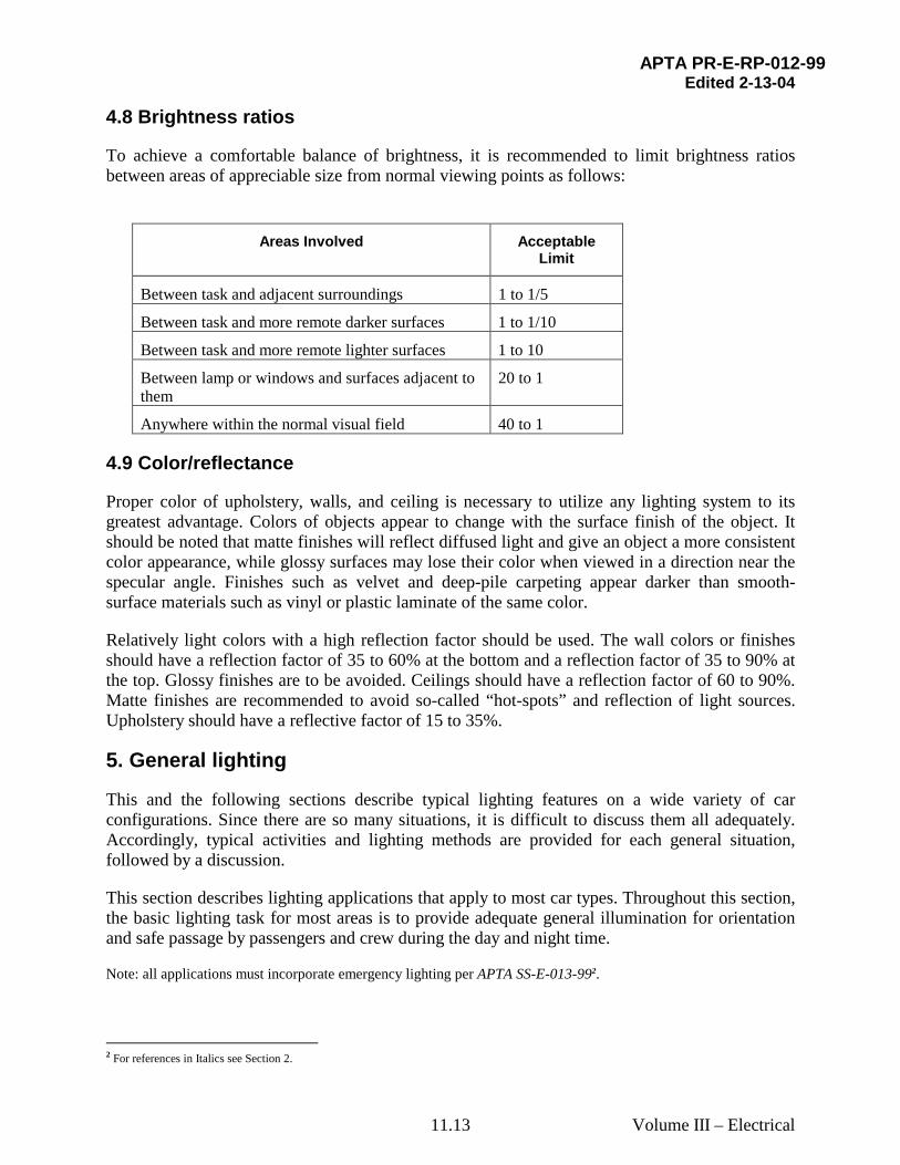
4.8 Brightness ratios
To achieve a comfortable balance of brightness, it is recommended to limit brightness ratios between areas of appreciable size from normal viewing points as follows:
Areas Involved Acceptable
Limit
Between task and adjacent surroundings 1 to 1/5
Between task and more remote darker surfaces 1 to 1/10
Between task and more remote lighter surfaces 1 to 10
Between lamp or windows and surfaces adjacent to them
20 to 1
Anywhere within the normal visual field 40 to 1
4.9 Color/reflectance
Proper color of upholstery, walls, and ceiling is necessary to utilize any lighting system to its greatest advantage. Colors of objects appear to change with the surface finish of the object. It should be noted that matte finishes will reflect diffused light and give an object a more consistent color appearance, while glossy surfaces may lose their color when viewed in a direction near the specular angle. Finishes such as velvet and deep-pile carpeting appear darker than smooth-surface materials such as vinyl or plastic laminate of the same color.
Relatively light colors with a high reflection factor should be used. The wall colors or finishes should have a reflection factor of 35 to 60% at the bottom and a reflection factor of 35 to 90% at the top. Glossy finishes are to be avoided. Ceilings should have a reflection factor of 60 to 90%. Matte finishes are recommended to avoid so-called “hot-spots” and reflection of light sources. Upholstery should have a reflective factor of 15 to 35%.
5. General lighting
This and the following sections describe typical lighting features on a wide variety of car configurations. Since there are so many situations, it is difficult to discuss them all adequately. Accordingly, typical activities and lighting methods are provided for each general situation, followed by a discussion.
This section describes lighting applications that apply to most car types. Throughout this section, the basic lighting task for most areas is to provide adequate general illumination for orientation and safe passage by passengers and crew during the day and night time.
Note: all applications must incorporate emergency lighting per APTA SS-E-013-992.
2 For references in Italics see Section 2.
APTA PR-E-RP-012-99 Edited 2-13-04
Volume III – Electrical 11.14
5.1 Entrance/exit–vestibule
5.1.1 Activities
– Safe passage
– Reading tickets to determine assigned seats or accommodations (except on commuter equipment)
– Reading signage
5.1.2 Typical lighting methods
– Ceiling lighting
– Spot light to shine on platform outside
The areas of interest are on the platform, steps and vestibule floor near the entrance/exit. The lighting for these areas are all horizontal at floor level. The viewing angle is practically vertical for the person to observe the condition of the tread surface and platform alignment with the car floor.
The entrance/exit and vestibule areas should be lighted to allow safe and rapid boarding and detraining of passengers and luggage.
Ceiling mounted fluorescent lighting should be arranged to provide good general lighting levels within the entrance/vestibule area, as well as the step area (if equipped). ADA requirements for threshold, whether high or low platform, and exterior platform light levels are identified in 49 CFR 38.101 and 49 CFR 38.1573. Car lighting should provide some light out onto the station platform for about 4 feet horizontally: on high platforms, to identify the gap between the platform and vehicle, on low platforms, the area in front of the step(s). This can be accomplished with ceiling fixture location or by providing a separate spotlight fixture.
The minimum illumination should be 5 foot-candles (54 lux) on the platform of the car directly beneath the fixture, 5 foot-candles (54 lux) at the threshold with the door open, 5 foot-candles (54 lux) on the center of each step (if equipped), and 2 foot-candles (22 lux) on the exterior platform at all points perpendicular to the door threshold for a distance of 3 feet (91 cm), whether high or low platform.
5.2 Diaphragm area
On car ends without vestibules, a small light fixture mounted overhead, can be used to provide illumination within the diaphragm and adjacent area, to allow safe passage.
The minimum illumination is a spatial average of 5 foot-candles (54 lux) at floor level.
3 For references in Italics, see Section 2.
APTA PR-E-RP-012-99 Edited 2-13-04
Volume III – Electrical 11.15
5.3 Stairway (interior)
5.3.1 Activities
• Safe passage
5.3.2 Typical lighting methods
• Small light on each step and landing.
• Overhead and/or side wall supplement.
Interior stairways require illumination for safe passage. These are areas where many injuries occur. Lighting should include a small fixture in the side-wall for each step and landing or equivalent. This lighting is often supplemented by ceiling or wall mounted fixtures. It is desirable to optically highlight the edge wrap of the top and bottom steps so they are easily identified by visually impaired passengers.
The minimum spatial average illumination is 5 foot-candles (54 lux) measured along the center of each step and landing, as well as the floor level immediately adjacent to the top and bottom step.
5.4 Passageway
5.4.1 Activities
– Safe passage
5.4.2 Typical lighting method
– Ceiling lights
– Recessed lighting in sidewall near floor (optional)
Passageway lighting requires considerable care in day/night operation to balance the need for passenger movement with the need for subdued light levels so not to interfere with sleep. Care should be taken in fixture placement so light does not shine into eyes of seated passengers at night. Highly directional lighting is often required, with particular care taken to avoid bright edges on the lens. The side wall surface material and flooring reflectivity are important considerations. Uniformity of lighting throughout the length of the passageway is desired.
The minimum spatial average illumination is 5 foot-candles (54 lux) measured along the centerline of the passageway at the floor.
APTA PR-E-RP-012-99 Edited 2-13-04
Volume III – Electrical 11.16
5.5 Aisle
5.5.1 Activities
– Safe passage
– Seat selection
5.5.2 Typical lighting method
– Row(s) of lights along center or side of ceiling
The areas of interest are to be able to observe the floor area for obstacles and the seat area for accommodations. The plane of the area for walking is at floor level and at 33” (84 cm) above the floor for seat selection. When seat numbers are provided such as along the edge of the luggage rack, this should be co-ordinated with the lighting to make the seat numbers easy to read.
In day/night operation, aisle lighting requires considerable care to balance the need for passenger orientation with the need for subdued light levels. One approach is a dual lamp fixture, which employs blue lamps (or lens) for night and clear lamps for the emergency function. Other alternatives include staged light circuits or dimming selected circuits.
The minimum spatial average illumination is 5 foot-candles (54 lux) measured along the centerline of the aisle at the floor.
For seat selection, the minimum spatial average illumination is 5 foot-candles (54 lux) measured on a horizontal plane at 33” (84 cm) above the floor along centerline of the aisle.
5.6 Toilet Area
5.6.1 Activities
– Toilet use
– Hand/face washing
– Changing clothes
– Grooming, including shaving and application of make-up
– Baby diaper changing and related activities
5.6.2 Typical lighting methods
– Single fixture over mirror
– General ceiling mounted fixture
The most visually demanding tasks usually are shaving and applying makeup. This is because the apparent distance of the face or figure as viewed in the mirror is twice its actual distance from the
APTA PR-E-RP-012-99 Edited 2-13-04
Volume III – Electrical 11.17
mirror, and the details to be seen in shaving and critical inspection are usually small and of low contrast with the background.
Since most toilet rooms are rather small, a single fluorescent fixture over the mirror works wel1.
For the use of mirrors, the minimum illumination value is 30 foot-candles (323 lux) on the face, measured in a vertical plane at a distance of 16” (41 cm) from the plane of the mirror, 62” (1.57 m) above the floor. Supplementary mirror fixtures or careful planning of the overall lighting may achieve this.
Large rooms, such as those, which are ADA accessible, may require an additional general lighting fixture.
The minimum spatial average illumination is 15 foot-candles (162 lux) measured on a horizontal plane 33” (84 cm) above the floor.
5.7 Electric/Switch Locker
5.7.1 Activities
– Read labels on switches, other controls and indicators
– Inspect, maintain and service electrical and mechanical equipment
5.7.2 Typical lighting methods
– Single fixture(s)
The task is to be able to operate or service any of the switches or controls inside the electric/switch locker. The light level should be sufficient and located so as to allow service personnel to work in the space without requiring addition light, such as a flashlight.
The walk-in style electric locker should be provided with an interior light, controlled by a door operated switch. This light should be powered directly from a battery so that it is available under all conditions (normal and emergency).
Likewise, a shallow switch or electric locker should be lighted in a similar fashion, unless it receives good light from an adjacent battery-supported source that is always illuminated.
5.8 Service lighting
5.8.1 Activities
– Read labels on switches, other controls and indicators
– Inspect, maintain and service electrical and mechanical equipment
5.8.2 Typical lighting methods
– Single fixture(s)
APTA PR-E-RP-012-99 Edited 2-13-04
Volume III – Electrical 11.18
The task is to be able to operate or service any switches or controls inside equipment rooms, lockers, etc. Service lighting should be provided and located in equipment rooms, lockers & closets, storage spaces and overhead equipment spaces, etc, to allow maintenance personnel to perform routine work on car equipment without the need to use portable lighting such as a flashlight.
The lighting should be turned off automatically when the door or access panel is closed. The fixtures should be moisture resistant and be provided with guards to protect the lamps from breakage and to avoid personnel injury from burns.
6. Coach lighting
General lighting functions for these car types are described in section 5.
There are two main coach types, commuter and intercity coach cars. Intercity coaches may be of the short or long distance type. These are the most common car types. Short distance coaches have moderate seat densities and operate primarily in regional services, with trip times of up to 12 hours. Long distance coaches offer low seat densities and trip times up to 3 days. Both types of intercity coaches include luggage racks, which significantly affect overhead lighting operation.
An intercity coach provides more kinds of service than any other passenger cars. It may be in use twenty-four hours per day and combine all the varying functions of the specialized cars. In addition to the coaches daytime use by passengers who wish to view scenery, read or relax in comfort, it also provides service during the evening and night hours when its utility and comfort depend in large measure on the design of the lighting system. In the early evening hours, the passengers may wish to talk, read, eat, drink or just relax. Later, while the majority would wish to sleep, there may be some that would like to continue reading. The lighting system or operating procedure should provide for this, as well as safe movement through the car by both passengers and crew when lighting is dimmed for the night operation.
6.1 Commuter coach
6.1.1 Activities
– Looking out the window
– Reading/writing
– Ticket collection and related transactions
– Car cleaning and maintenance
– Using laptop computer
6.1.2 Typical lighting method
– The general lighting is required, refer to section 5.
– General ceiling lighting – center or cover
APTA PR-E-RP-012-99 Edited 2-13-04
Volume III – Electrical 11.19
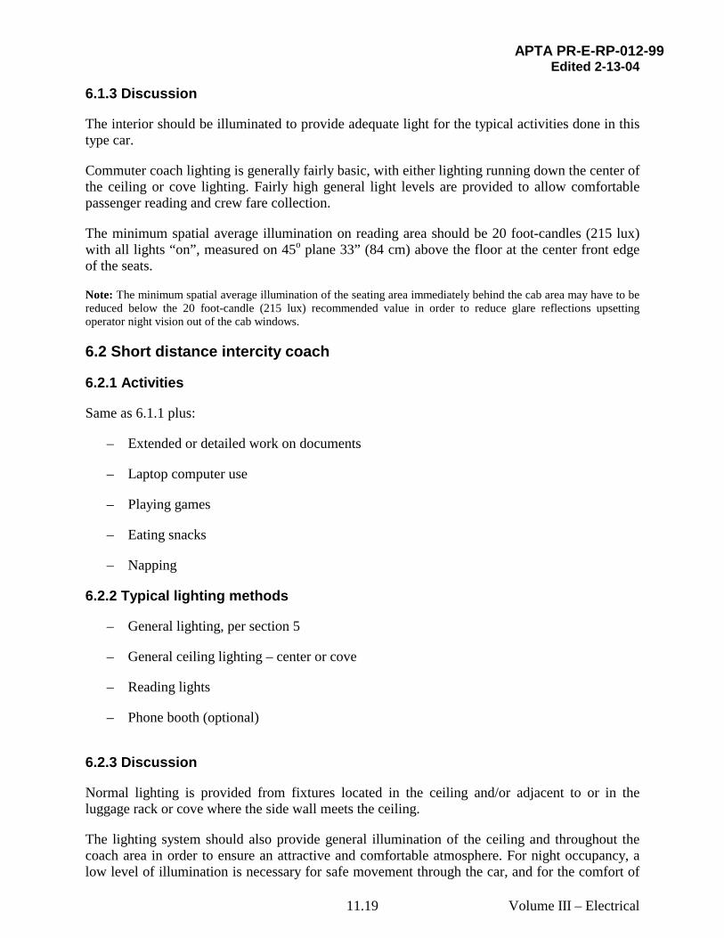
6.1.3 Discussion
The interior should be illuminated to provide adequate light for the typical activities done in this type car.
Commuter coach lighting is generally fairly basic, with either lighting running down the center of the ceiling or cove lighting. Fairly high general light levels are provided to allow comfortable passenger reading and crew fare collection.
The minimum spatial average illumination on reading area should be 20 foot-candles (215 lux) with all lights “on”, measured on 45o plane 33” (84 cm) above the floor at the center front edge of the seats.
Note: The minimum spatial average illumination of the seating area immediately behind the cab area may have to be reduced below the 20 foot-candle (215 lux) recommended value in order to reduce glare reflections upsetting operator night vision out of the cab windows.
6.2 Short distance intercity coach
6.2.1 Activities
Same as 6.1.1 plus:
– Extended or detailed work on documents
– Laptop computer use
– Playing games
– Eating snacks
– Napping
6.2.2 Typical lighting methods
– General lighting, per section 5
– General ceiling lighting – center or cove
– Reading lights
– Phone booth (optional)
6.2.3 Discussion
Normal lighting is provided from fixtures located in the ceiling and/or adjacent to or in the luggage rack or cove where the side wall meets the ceiling.
The lighting system should also provide general illumination of the ceiling and throughout the coach area in order to ensure an attractive and comfortable atmosphere. For night occupancy, a low level of illumination is necessary for safe movement through the car, and for the comfort of
APTA PR-E-RP-012-99 Edited 2-13-04
Volume III – Electrical 11.20
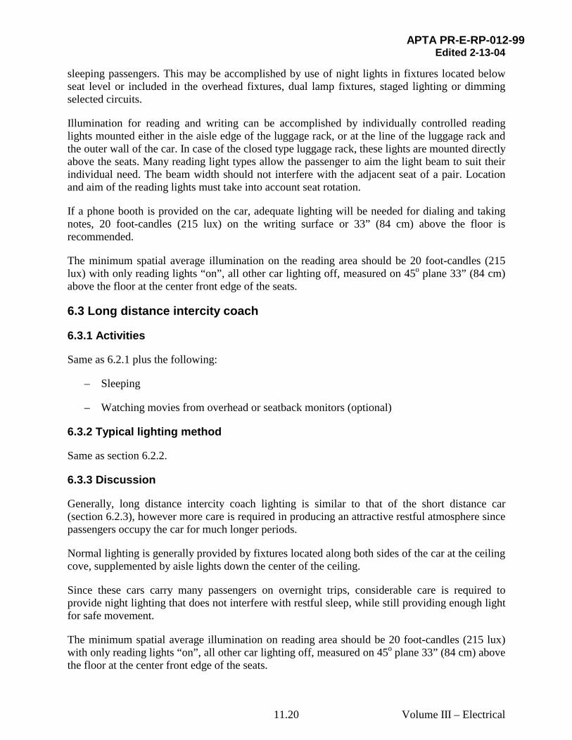
sleeping passengers. This may be accomplished by use of night lights in fixtures located below seat level or included in the overhead fixtures, dual lamp fixtures, staged lighting or dimming selected circuits.
Illumination for reading and writing can be accomplished by individually controlled reading lights mounted either in the aisle edge of the luggage rack, or at the line of the luggage rack and the outer wall of the car. In case of the closed type luggage rack, these lights are mounted directly above the seats. Many reading light types allow the passenger to aim the light beam to suit their individual need. The beam width should not interfere with the adjacent seat of a pair. Location and aim of the reading lights must take into account seat rotation.
If a phone booth is provided on the car, adequate lighting will be needed for dialing and taking notes, 20 foot-candles (215 lux) on the writing surface or 33” (84 cm) above the floor is recommended.
The minimum spatial average illumination on the reading area should be 20 foot-candles (215 lux) with only reading lights “on”, all other car lighting off, measured on 45o plane 33” (84 cm) above the floor at the center front edge of the seats.
6.3 Long distance intercity coach
6.3.1 Activities
Same as 6.2.1 plus the following:
– Sleeping
– Watching movies from overhead or seatback monitors (optional)
6.3.2 Typical lighting method
Same as section 6.2.2.
6.3.3 Discussion
Generally, long distance intercity coach lighting is similar to that of the short distance car (section 6.2.3), however more care is required in producing an attractive restful atmosphere since passengers occupy the car for much longer periods.
Normal lighting is generally provided by fixtures located along both sides of the car at the ceiling cove, supplemented by aisle lights down the center of the ceiling.
Since these cars carry many passengers on overnight trips, considerable care is required to provide night lighting that does not interfere with restful sleep, while still providing enough light for safe movement.
The minimum spatial average illumination on reading area should be 20 foot-candles (215 lux) with only reading lights “on”, all other car lighting off, measured on 45o plane 33” (84 cm) above the floor at the center front edge of the seats.
APTA PR-E-RP-012-99 Edited 2-13-04
Volume III – Electrical 11.21
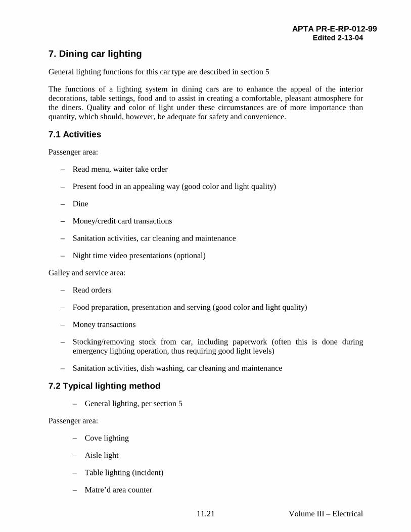
7. Dining car lighting
General lighting functions for this car type are described in section 5
The functions of a lighting system in dining cars are to enhance the appeal of the interior decorations, table settings, food and to assist in creating a comfortable, pleasant atmosphere for the diners. Quality and color of light under these circumstances are of more importance than quantity, which should, however, be adequate for safety and convenience.
7.1 Activities
Passenger area:
– Read menu, waiter take order
– Present food in an appealing way (good color and light quality)
– Dine
– Money/credit card transactions
– Sanitation activities, car cleaning and maintenance
– Night time video presentations (optional)
Galley and service area:
– Read orders
– Food preparation, presentation and serving (good color and light quality)
– Money transactions
– Stocking/removing stock from car, including paperwork (often this is done during emergency lighting operation, thus requiring good light levels)
– Sanitation activities, dish washing, car cleaning and maintenance
7.2 Typical lighting method
– General lighting, per section 5
Passenger area:
– Cove lighting
– Aisle light
– Table lighting (incident)
– Matre’d area counter
APTA PR-E-RP-012-99 Edited 2-13-04
Volume III – Electrical 11.22
Galley area:
– General lighting – ceiling
– Counter lighting
– Refrigerator lighting (large units only)
7.3 Discussion
7.3.1 Dining area
Dining areas can be adequately illuminated by means of two continuous rows of lamps, one on each side of the car. As dictated by interior design, the rows may be recessed in the ceiling with a diffusing medium below the lamps, or mounted in coves on each side of the car. The coves may be modified to obtain some direct “down” light in addition to that on the ceilings, or small incandescent lights recessed in the cove or along wall above windows may be added over each table. Where indirect cove lighting is used, some additional light to accent the tables is generally necessary, and if not provided by direct “down” lighting, may be obtained by the use of incandescent table lamps on the wall side of each table. The selection of the system should be governed by the overall décor of the car and the effects desired. Direct “down” lighting on a table results in sparkle to the silverware and glassware that cannot be obtained from diffuse illumination, and is an important aid in the stimulation of eye appeal. The proper color characteristics of the light sources are important if the source is fluorescent. The presently designated Deluxe Warm White lamps provide overall color rendition that is complimentary to the appearance of people, food and interior furnishings.
The minimum spatial average general illumination for the dinning area should be 10 foot-candles (108 lux) at 33 inches (84 cm) above the floor.
Passengers need light for eating and drinking and for reading menus and checks.
The minimum spatial average illumination should be 15 foot-candles (162 lux), provided on a plane 45o up facing the seated diner, 8 inches (21 cm) from the front edge of the table.
7.3.2 Galley
High levels of quality illumination are required in the galley for the utmost efficiency of operating personnel. Good illumination also insures good appearance of food and its proper inspection. FDA lighting level requirements are identified in “US Public Health Service Food Code, 1997”.4
Quality of lighting is important, especially in regard to color. In addition to general lighting, usually supplied by ceiling mounted lamps, counter lighting should be provided over all work areas generally by fixtures mounted on the underside of overhead cabinets.
High levels of lighting are required where food is handled directly, such as cutting boards, etc. The work performed is preparing foods and beverages and cleaning the area. The task plane is
4 For references in Italics, see Section 2.
APTA PR-E-RP-012-99 Edited 2-13-04
Volume III – Electrical 11.23
horizontal on work counters 36 inches (91 cm) from the floor. Illumination should be provided on the work counters from the front to the back edge.
The area from which food is served whether between the kitchen and pantry, or separated, such as on a bi-level car, should be well lighted to facilitate food inspection.
Large refrigeration cabinets should have at least one lamp per compartment, operated by automatic door switches.
Since stocking the car is often done with main power off, high levels of emergency light are necessary. This is usually done by equipping a number of ceiling and/ or counter fixtures with inverter ballasts and powering them from the car battery system.
Good light levels are needed for dish washing and general galley sanitation.
Galley and serving area minimum spatial average illumination shall be:
Food storage area: 10 foot-candles (108 lux), measured in a vertical plane, measured on cabinet doors
Food preparation area: 20 foot-candles (215 lux) measured on counter
Food handling, cutting use of utensils, preparation: 50 foot-candles (538 lux) on counter
Food serving area: 20 foot-candles (215 lux) on counter
Hand, dish washing: 20 foot-candles (215 lux) on counter
8. Short distance snack car (light food service) lighting
General lighting functions for this car type are described in section 5.
Short distance snack cars generally include some combination of coach seating, table seating and a food service area, though all cars do not necessarily include all three. A common floor plan includes the food service area in the center, with a passenger area on both ends of the car. Coach seating could be provided at both ends of the car, table seating provided at both ends of the car, or coach seating on one end and table seating at the other.
The function of the lighting, especially in the food service area, is to provide an appealing atmosphere in which to select, purchase and consume snacks and light meals.
8.1 Activities
Passenger area:
– Looking out window (lighting should not interfere)
– Extended or detailed work on documents
– Laptop computer use
APTA PR-E-RP-012-99 Edited 2-13-04
Volume III – Electrical 11.24
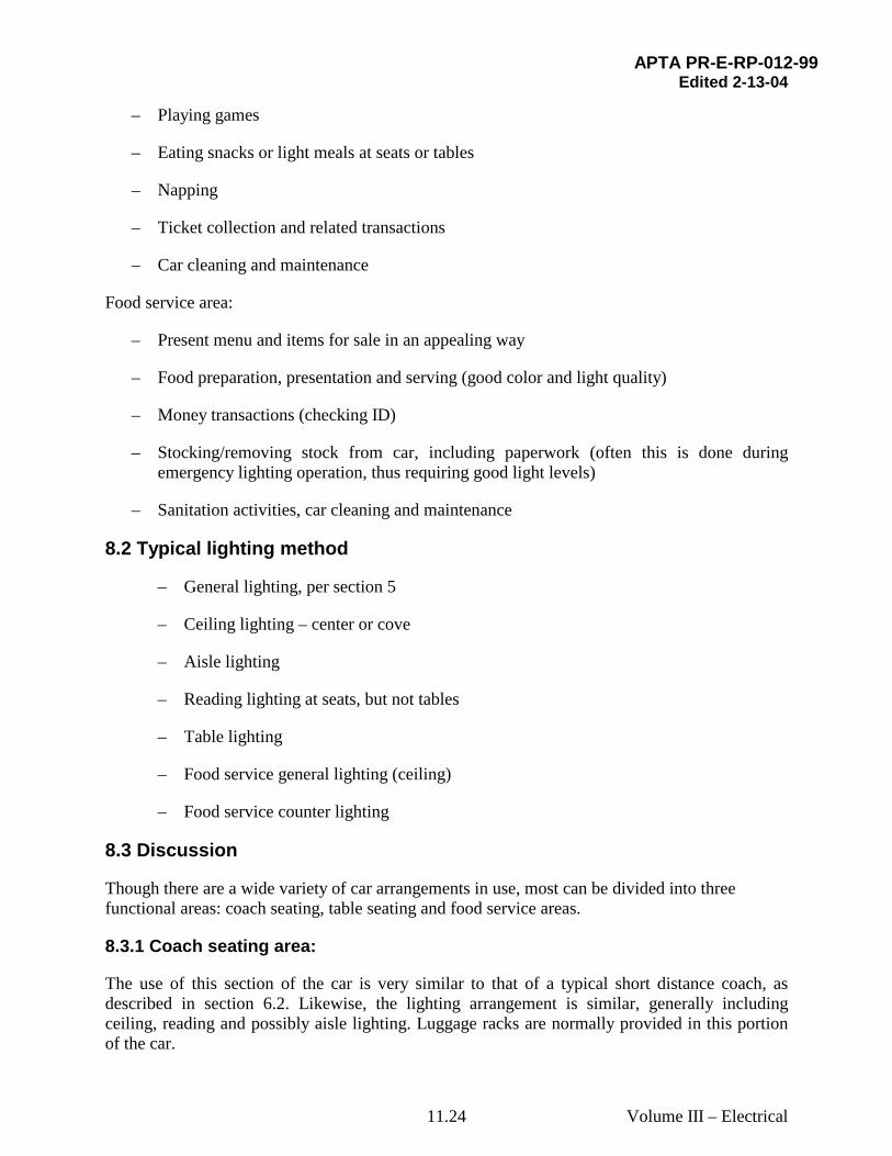
– Playing games
– Eating snacks or light meals at seats or tables
– Napping
– Ticket collection and related transactions
– Car cleaning and maintenance
Food service area:
– Present menu and items for sale in an appealing way
– Food preparation, presentation and serving (good color and light quality)
– Money transactions (checking ID)
– Stocking/removing stock from car, including paperwork (often this is done during emergency lighting operation, thus requiring good light levels)
– Sanitation activities, car cleaning and maintenance
8.2 Typical lighting method
– General lighting, per section 5
– Ceiling lighting – center or cove
– Aisle lighting
– Reading lighting at seats, but not tables
– Table lighting
– Food service general lighting (ceiling)
– Food service counter lighting
8.3 Discussion
Though there are a wide variety of car arrangements in use, most can be divided into three functional areas: coach seating, table seating and food service areas.
8.3.1 Coach seating area:
The use of this section of the car is very similar to that of a typical short distance coach, as described in section 6.2. Likewise, the lighting arrangement is similar, generally including ceiling, reading and possibly aisle lighting. Luggage racks are normally provided in this portion of the car.
APTA PR-E-RP-012-99 Edited 2-13-04
Volume III – Electrical 11.25
8.3.2 Table seating area:
Tables are provided, usually with bench type seating, in this area of the car. These tables are generally used for eating light meals and also see frequent use in a business environment, either used as a desk, or a place to have a meeting. Lighting generally includes ceiling and possibly aisle lighting. Reading lights are not normally provided. Luggage racks are not normally installed in this portion of the car.
8.3.3 Food service area:
This area normally includes a food preparation and serving counter where passengers come to select and purchase drinks, snacks and light meals. Food is served, generally in a pre-packed form, with preparation usually limited to heating and dispensing. These items are either consumed within the car, or taken elsewhere in the train. Selection is made from wall-mounted menus. Good color rendition is essential to provide appealing offering to the passengers.
High light levels must be provided to meet FDA requirements, as identified in “US Public Health Service Food Code, 1997”. 5
Ceiling lighting is typically provided directly over the serving counter, with counter lighting provided over all work areas, from front to back, generally by fixtures mounted on the underside of overhead cabinets.
Effective lighting of the menus needs to be included in the overall lighting design.
Since stocking the car is often done with main power off, high levels of emergency light are necessary. This is usually done by equipping a number of ceiling fixtures with inverter ballasts and powering them from the car battery system.
Minimum spatial average illumination should be:
Coach area: The minimum spatial average illumination on the reading area should be 20 foot-candles with only reading lights “on”, all other car lighting off, measured on 45o plane 33” above the floor at the center front edge of the seats.
Table area: 15 foot candles (162 lux) on the table at each seat position
Food storage area: 10 foot-candles (108 lux), measured in a vertical plane on cabinet doors
Food preparation area: 20 foot-candles (215 lux) on the counter
Food serving area: 20 foot-candles (215 lux) on the counter
9. Sleeping car lighting
General lighting functions for this car type are described in section 5.
5 For references in Italics, see Section 2.
APTA PR-E-RP-012-99 Edited 2-13-04
Volume III – Electrical 11.26
The lighting design of the sleeping car should lend to the comfort, convenience and beauty of the accommodations. Creating a relaxed environment is especially important since passengers occupy the room for up to three (3) days. As in any good lighting installation, the ability to perform the visual task is the primary consideration. Lighting design is difficult, due to the many seeing activities and severely limited wall and ceiling area available for mounting fixtures. Ergonomic issues are very important, since not only must the lighting be oriented correctly, but also the controls must be located logically and be easy to use, especially those for the upper berth.
9.1 Activities
Passenger area:
– Looking out window (lighting should not interfere)
– Reading, writing, studying documents, illustrations, etc. both in seat and in bed, without disturbing other room occupant(s)
– Laptop computer use
– Playing games
– Dining or eating snacks
– Sleeping in bed
– Ticket collection and related transactions
– Car cleaning and maintenance
– Child care, baby diaper changing and related activities
– Changing linen and making up beds
– Toilet use (some car type and accommodation types only, toilet may be in room itself, or a small room within the accommodation; some cars also have public toilets and showers)
– Hand and face washing, grooming, including shaving and application of make-up
– Changing clothes
– Taking a shower
9.2 Typical lighting method
– General lighting, per section 5
– General room lighting (ceiling with night light and wall light)
– Reading lighting
– Berth light
APTA PR-E-RP-012-99 Edited 2-13-04
Volume III – Electrical 11.27
– Mirror/ sink lighting
– Private or public toilet/ shower lighting
– Passageway (with room numbers) lighting
– Closet lighting
– Night light
9.3 Discussion
Room:
Room lighting and control must take into account that most rooms are occupied by two passengers, who may wish to do different activities. For example, one person could be asleep in the upper berth, while the second is using one of the seats and small folding table to write a letter. Another example is for the upper berth occupant to be reading, while the lower berth passenger sleeps. This lighting requirements in different parts of the room can be very different at the same time.
Lighting control must allow control of the main room light and night light from upper and lower berth positions. Controls must be easy to find and use in a dark room, especially since a passenger may be unfamiliar with the room layout and its features. Back-lighted switches have been successfully used for this purpose, but care must be taken to avoid this light being too bright.
General illumination can be provided from a combination of ceiling and mirror fixtures with possible supplement from wall mounted luminaries. A small fluorescent fixture, mounted over the room mirror, generally provides good lighting for sink use and grooming.
The general illumination should be such as to meet the requirements for lounging and to provide sufficient component of illumination to the upper walls and ceilings for the elimination of unpleasant contrasts. Supplementary lighting sources may be required to furnish the higher level of illumination required for prolonged reading and business work. Lamps should be arranged not to shine into eyes of other occupants. Berth lamps are furnished and so placed as to provide a suitable source for reading in bed. Bed lamps should be so designed as to provide a concentrated beam of light for the reading task and a component for general illumination to relieve excessive contrasts.
Private toilet rooms are usually illuminated with a ceiling-mounted fixture. When the toilet room is also used as a shower, the fixture must be water resistant and grounded.
General areas:
Passageway lighting should generally conform to the requirements of section 5.4 and is usually provided by small ceiling-mounted fixtures. They often include a lens, which indicates the room number. They may also incorporate features for the attendant call system, such as a light indicating service is desired.
Public toilets should generally conform to the requirements given in section 5.6. Likewise, public
APTA PR-E-RP-012-99 Edited 2-13-04
Volume III – Electrical 11.28
showers have similar requirements, with the additional requirement of water-resistant fixtures that are grounded.
A coffee station is provided on some equipment, which includes features such as a coffee maker, fruit juice dispenser, etc. Light must meet FDA requirements for sanitation in the area.
Miscellaneous closets and other larger storage spaces, such as linen lockers may be equipped with small door activated lights. Care needs to be taken to protect the lamp from overheating should it stay on and be exposed to the contents of the locker.
Minimum spatial average illumination shall be:
Reading: 20 foot-candles (215 lux), only reading light on, measured on a 45 degree plane, 33" (84 cm) above floor at the front edge of each seat.
Berth: 20 foot-candles (215 lux), only reading light on, measured on a 45 degree plane, with the height determined by comfortable passenger reclining position
Table: 20 foot-candles (215 lux), on the center of the table
General room: 20 foot-candles (215 lux), measured 33” (84 cm) above the floor
Mirror: 30 foot-candles (323 lux), measured in a vertical plane, 16" (41 cm) from the mirror, 62" (1.57 m) above the floor
Coffee station: 20 foot-candles (215 lux), on the counter
10. Long distance lounge and observation – car lighting
General lighting functions for this car type are described in section 5.
Modern lounge and observation cars are used to furnish extra convenience and comfort for railroad passengers and because of the different types of service they provide their lighting needs are many and varied. The problems involved in the lighting of these cars are a combination of those encountered in the lighting of the various areas of the other type cars as previously enumerated. Each of the areas listed has some lighting tasks that are not common to the other areas and should be treated separately and distinctly. Cars typically have three basic areas; lounge seating with clusters of seats surrounding small tables; table area with larger tables for light meals and playing games; and food service area, where snacks, drinks, and pre-packaged meals are prepared and served.
The function of the lighting is to provide a relaxing atmosphere for passengers in the lounge area, and in the food service area, to provide an appealing atmosphere in which to select, purchase and consume drinks, snacks and light meals.
Many of these cars are designed specifically for sightseeing and have vast areas of glass.
APTA PR-E-RP-012-99 Edited 2-13-04
Volume III – Electrical 11.29
Accordingly, considerable care is required in the lighting design to avoid reflections or glare from the lighting that would interfere with the view, especially at night.
10.1 Activities
Passenger area:
– Sight – seeing (lighting should not interfere)
– Extended or detailed work on documents
– Laptop computer use
– Playing games
– Eating snacks in lounge area
– Night time video presentations
– Napping
– Ticket collection and related transactions
– Car cleaning and maintenance
Food service area:
– Present menu and items for sale in an appealing way
– Food preparation, presentation and serving (good color and light quality)
– Dish washing, sanitation activities
– Money transactions (checking ID)
– Stocking / removing stock from car, including paperwork (often this is done during emergency lighting operation, thus requiring good light levels)
– Car cleaning and maintenance
10.2 Typical lighting method
– Basic lighting, per section 5
– Cove lighting
– Aisle lighting
– Reading lighting
– Table lighting
APTA PR-E-RP-012-99 Edited 2-13-04
Volume III – Electrical 11.30
– Food service general lighting (ceiling)
– Food service counter lighting
10.3 Discussion
Though there are a wide variety of car arrangements in use, most can be divided into three functional areas: lounge seating, table seating and food service areas.
Lounge seating area:
The lighting tasks consist mostly of seeing requirements for reading and lounging. This area generally includes cove and aisle lighting, with the cove lighting switched off at night on sightseeing type equipment. Spot or reading lights, individually controlled, may be provided over the small tables and/or seats in the area.
In the dead-end, observation type car, the fixtures preferably are extended to meet at the rear of the car, conforming to its curvature. Special lighting may be added, such as table fixtures, mirror or picture illumination to add lighting interest and also suitable dimming or night light features. If cars are used to show videos at night, suitable night lighting should be present.
Table seating area:
Tables are provided, usually with bench type seating, in this area of the car. These tables are generally used for eating light meals, card playing and also see some use in a business environment, being used as a desk. Lighting generally includes ceiling and possibly aisle lighting.
Food service area:
This area normally includes a food preparation and serving counter where passengers come to select and purchase drinks, snacks and light meals. It may take two forms:
– Serving counter where customers make selections from wall-mounted menus
– Area equipped with glass display cases from which customers make their own selections.
Food is served, generally in a pre-packed form, with preparation usually limited to heating and dispensing. These items are either consumed within the car, or taken elsewhere in the train. Good color rendition is essential to provide appealing offerings to the passengers.
High light levels must be provided in the food service area to meet FDA requirements, as identified in “US Public Health Service Food Code, 1997”. 6
Ceiling lighting is typically provided directly over the serving counter, with counter lighting provided over all work areas, from front to back, generally by fixtures mounted on the underside of overhead cabinets. Additional accent lighting may be installed on the front of the counter area for visual interest.
Effective lighting of the menus needs to be included in the overall lighting design.
6 For references in Italics, see Section 2.
APTA PR-E-RP-012-99 Edited 2-13-04
Volume III – Electrical 11.31
Since stocking the car is often done with main power off, high levels of emergency light are necessary. This is usually done by equipping a number of ceiling fixtures with inverter ballasts and powering them from the car battery system.
Minimum spatial average illumination should be:
Lounge area: 20 foot-candles (215 lux), with only reading (or spot) light on, measured on a 45 degree plane, 33" (84 cm) above the floor at the front edge of each seat
Table area: 15 foot-candles (162 lux) on the table at each seat position
Food storage area: 10 foot-candles (108 lux), measured in a vertical plane, on cabinet doors
Food preparation area: 20 foot-candles (215 lux) on the counter
Food serving area: 20 foot-candles (215 lux) on the counter
11. Baggage car or bag area of combination cars
General lighting functions for this car type are described in section 5.
11.1 Activities
– Read labels attached to baggage / packages
– Safely handle baggage and other articles into and out of the car in dark station areas
– Car cleaning and maintenance
11.2 Typical lighting method
– General lighting, per section 5 (limited areas apply)
– General ceiling lighting
– Loading door lighting
11.3 Discussion
Low temperature fluorescent, weather-resistant fixtures should be provided along the ceiling of the car. An incandescent light fixture should be provided over each side loading-door of the car. It should provide sufficient light both inside and outside the car to allow safe and efficient baggage handling to and from an unlighted station platform. All car lighting should be battery supported.
Minimum light levels:
Floor 5 foot-candles (54 lux)
APTA PR-E-RP-012-99 Edited 2-13-04
Volume III – Electrical 11.32
At loading door threshold 5 foot-candles (54 lux)
Baggage shelves, if provided 5 foot-candles (54 lux) at aisle on floor
12. Fixture design
The light distribution and the lighting fixtures form an important part of the interior furnishings and must meet the specified requirements for appearance, color schemes, and blending with the interior design concepts.
Lighting in each car type should be designed by the Contractor to meet the illumination requirements specified in Sections 5 through 11. The lighting arrangement for each car type should be designed to minimize the load during battery operation. Common fixtures and fixture components should be used to the greatest extent possible between car types.
The lighting fixtures should be designed to produce a uniform brightness of evenly distributed light, free from glare, high intensity spots, beams, beam holes, edge scatter, or patterns of light.
The fixture should not deteriorate rapidly in effectiveness through the collection of dirt and should permit easy cleaning and easy lamp renewal. Interior fixtures should be dust-resistant; those in wet areas, such as equipment areas, food service areas, showers and toilets should be moisture-proof.
Design of the lighting fixtures and their deployment should minimize the number of lamp types required, and unique fixtures used. To the extent possible, lenses, sockets, ballasts, and fasteners should be interchangeable among all fixtures. Likewise sockets, lamp holders, and switches should be readily available from multiple U.S. sources. To the extent possible, sockets and lamps should be selected so it is impossible to insert the wrong lamp into a socket (i.e., candelabra bases could be used for DC battery circuits, with bayonet bases used for AC circuits). Fixtures should be either repairable in place (eg. Ballast change out, socket replacement), or be easily removable for bench repair. In order to avoid dark spots, adjacent fixtures should not be fed from the same ballast.
12.1 Mechanical design features
The lighting fixture should be free from rattles and designed to prevent resonance. The fixtures should be designed to last for the life of the vehicle. The lighting fixture surfaces and parts with which the passengers or crew could possibly come into contact should not have surface temperatures in excess of 125°F. (52oC.). The fixtures should be fabricated in such a way that when mounted in the car, no hardware such as bolt heads, screw heads, or fasteners will show from the passengers’ walking or seated fields of vision, except those that may be required for releasing the door assembly for relamping. Fasteners used to secure door assembly should be captive. All materials used in the manufacture of reflectors, components, and housing should meet the flammability, smoke emission, and toxicity requirements specified by the railroad. Lamps, fixtures, reflectors, diffusers, and shades should meet interior color rendering and background effects requirements.
12.2 Reflectors
All fixtures should be equipped with reflectors of any suitable combination of white, matte silver
APTA PR-E-RP-012-99 Edited 2-13-04
Volume III – Electrical 11.33
chrome plate or aluminum finish. Fixtures should all be tarnish-, rust-, corrosion-, and mark-resistant for the typical car interior environment. The fixtures should be easy to clean without susceptibility to scratching, pitting, or loss of original color and surface texture.
12.3 Construction
The design of the lighting system, lighting fixtures and various components should ensure that adequate space is provided to prevent any wiring from being crushed by mechanical components, being sharply bent, or located adjacent to surfaces where vibrations could create failure due to insulation abrasion. Adequate clearance should also be provided between all exposed electrical contacts and terminals and adjacent conductive components and surfaces. Such clearances should be in accordance with acceptable manufacturing practices. Each metal body fixture should employ ground wiring to bond it to the car body.
Wiring should be stranded wire in accordance with APTA RP-E-009-987. General wiring should be in accordance with APTA RP-E-002-98. Wiring will be terminated using crimp-type pre-insulated ring-tongue lugs. Alternatively, car wiring may be connected to the fixtures through the use of railroad approved connectors. Different connectors or keying should be employed if more than one connector is used on a fixture. Connectors should be selected for durability and very long term availability.
Wiring should be adequately secured in position, using ty-wraps, screw-down cable clamps, etc. Cable clamps secured to the panel by an adhesive are not acceptable for this purpose. All wires should be labeled on both ends. Wires 4” or less in length needs only one (1) label. Ballast wiring, internal to the fixture may be color coded as an alternative.
12.4 Identification
Each light fixture should have a permanent label and/or stamping, visible when the light cover is removed or swung down, that contains the following information:
– Supplier part number;
– Railroad part number;
– Voltage;
– Lamp identification, including fluorescent color, maximum wattage and required wattage.
12.5 Fluorescent fixtures
12.5.1 Fixtures
The fluorescent lighting fixtures should contain 37 or 74 VDC inverter ballasts and/or 240 or 120 VAC ballasts. If possible, all ballas’s should be integral parts of the fixtures, conveniently located and easily removed from the fixtures without disturbing other components and wiring.
7 For references in Italics, see Section 2.
APTA PR-E-RP-012-99 Edited 2-13-04
Volume III – Electrical 11.34
12.5.2 Fixture dockets
Fluorescent fixture lamp-holder sockets should be designed to support the ends of the lamp, in addition to that obtained from the terminal pins. This feature should be achieved by an approved built-in locking device, such as in the lock sockets. Lamp-holders should meet or exceed the requirements of UL542.
12.5.3 Lens and covers
All fluorescent fixtures should have lenses of a UV stabilized polycarbonate. Alternatives will be considered, including designs incorporating louvers, provided that the issue of cleaning can be resolved, and subject to design review. The lenses should not have any edge gaps or holes enabling raw light to be directly visible from bulbs or reflectors. All reflectors should be designed to minimize dust accumulation, and be easy to clean. All covers should be designed to minimize dust accumulation.
Overhead light assemblies should be designed for relamping from below by swinging down the lens door assembly. Fasteners securing the door should not be mounted directly in the polycarbonate to avoid cracks.
12.5.4 Ballast
An integral ballast(s) designed for proper operation of lamps, should be mounted for ease of maintenance within the fixture. This can take the form of surface-mount, or a mounting on the back side of a hinged door secured with captive hardware. Accessibility to the ballast wiring must also be addressed. If the ballast includes an indicator light, this should be easily visible with the lens cover open.
In order to avoid large dark spots when a ballast fails, adjacent fixtures should not be powered from the same ballast. However, wiring runs of the ballast wiring should be kept under 10 feet.
All ballast should meet the requirements of UL595 and ANSI C82.
12.5.4.1 AC ballast
All AC ballasts should be US source, high efficiency, high power factor, rapid start units. The ballast must not sustain damage from removing a lamp while in operation. Required features include:
Starting temperature 50 degrees F or lower
Sound rating A
Class P
12.5.4.2 DC (inverter) ballast
All inverter ballasts should be US source, rapid start, high efficiency, high frequency units (20KHz or above). The ballast must not sustain damage from removing a lamp while in operation. Required features include:
APTA PR-E-RP-012-99 Edited 2-13-04
Volume III – Electrical 11.35
Starting temperature 50 degrees F or lower
Sound rating A
Input voltage range Designed to operate normally from the nominal supply voltage, with capability for continuous operation over full input range, self protected against low, high and reversed polarity input.
12.6 Incandescent light fixtures
12.6.1 Lens and covers
All incandescent fixtures should have lenses of molded, UV stabilized, translucent or frosted white polycarbonate and should deliver light evenly, free from glare when viewed directly. Alternative materials will be considered, subject to design review. All lenses and/or door assemblies should swing down or be removable from the front for renewing bulbs. The cover/lenses should be designed to distribute the light evenly on the surface area. Reading and general incandescent lamps should have lenses that will aid in light distribution, prevent glare and facilitate easy bulb replacement.
12.7 Reading lights
Reading lights are generally incandescent, with halogen lamps becoming popular in recent years. A switch is normally provided to allow individual control of each light by the passenger. Fixtures can usually be aimed by the passenger to suit their individual needs, in both a lateral and longitudinal directions. If a reflector is used, it is highly desirable for it to be part of the fixture itself, rather than to be part of the bezel assembly. The reading light switch must be selected for a very high cycle life, in excess of 300,000 cycles at rated load, due to the frequent use. Since reading light fixtures are normally quite compact and are equipped with fairly high wattage lamps, considerable care is necessary to ensure that the surfaces which can be touched by the user do not exceed 140oF. (60oC.). The switch should be mounted in such way that it is accessible for servicing/replacement without major effort.
12.8 Lamps
Lamps should be chosen which are suitable for the rough duty service found in the normal railroad environment. Without sacrificing lighting performance, the number of different types of lamps required should be kept to a minimum, preferably those already in use by the railroad. Only lamp types readily available in the US market place should be used. Fluorescent lighting is preferred over incandescent, wherever it does not compromise lighting function.
Fluorescent lamps should be rapid start, energy-efficient, long life types, such as T-8, and compact types such as PL-9, which meet EPACT standards. Lamp color should be determined by interior design considerations.
12.9 Controls
Lighting controls should be obvious in use and convenient to the passenger as appropriate or crew. Switches must be of high quality, have a very high cycle life (300,000 cycles or more) and be dust resistant. Switches in potentially wet locations should be waterproof. They should be
APTA PR-E-RP-012-99 Edited 2-13-04
Volume III – Electrical 11.36
mounted in such a way as to not work loose on the mounting. On ferrule-mounted switches, this includes providing keying in the key way. Switches should be mounted in such a way as to make them available for servicing/replacement without major effort in disassembly of the car interior.
Switches should be provided to control main lighting, rather than relying on circuit breakers to act as switches.
Lighting controls should be clearly labeled with permanent labels. Where functions are complicated, such as those in a sleeping car room, an instruction label may be appropriate.
Accessible locations must be equipped with controls in compliance with ADA requirements, as identified in 49 CFR Part 38.127.
13. Design reviews and first article inspection
13.1 Design reviews
Since engineering design for passenger car lighting is complex, design review at several stages is recommended.
Information should be provided to the customer for approval for each car type as part of the design review:
– Location of all fixtures
– Identification of all fixture types
– Location and type of all light switches
– Lamp type(s) and quantity in each fixture
– Plan showing what lighting is illuminated during standby (if equipped) and emergency lighting modes.
13.2 First article inspection
A first article inspection should be conducted on all fixtures at the manufacturer’s facility, and an additional inspection on the finished car to determine the effectiveness of the design. Any deficiencies noted should be corrected.
14. Evaluation measurements and tests
14.1 General
An engineering type qualification test should be conducted on each car type to determine whether the design meets the requirements. A report should be provided to the railroad showing the light levels measured and procedure used to obtain the readings.
Since the primary considerations in railroad passenger car lighting vary with the accommodations and the task as described, evaluation measurements should be based on tasks or functions normally found in the full complement of railroad passenger cars. In evaluating the lighting
APTA PR-E-RP-012-99 Edited 2-13-04
Volume III – Electrical 11.37
system level for any particular car, the applicable combination of measurements will have to be employed. Testing is required for normal lighting and standby lighting if so equipped.
The test plan should be submitted for railroad approval prior to conducting the test. It should include each component type and each car configuration. A report should be provided showing the light levels measured and the detailed procedure(s) used to obtain the readings.
14.1.1 Universal factors
The following general factors apply to all tests:
– All extraneous light should be excluded.
– The voltage should be held constant at the nominal rated voltage at the breaker panel.
– Fluorescent lamps should be operated 100 hours before tests are made.
– Fluorescent systems should be lighted and the car at operating conditions before any readings are taken.
– When photoelectric cell type instruments are used, the car should be at a temperature above 60oF. (16oC.) and operated in accordance with the manufacturer’s operating instructions. This is not necessary with instruments that have temperature compensation built in.
– When testing the illumination of a car, a careful record should be taken of the condition of the car and the method of making the test. Information should include the following:
a) Name and number of car.
b) Location where test is made.
c) Names of those conducting test.
d) Date.
e) Time of day.
– Daylight with shades/ curtains drawn.
– Night with shades/ curtains drawn.
– Night with shades/ curtains up.
Note: Unshaded windows are black surfaces with very low reflectance factors. Shades are usually of a much higher reflectance value.
f) Instruments used, date of last calibration, and whether equipped with color correction filter.
g) Identification of area tested.
APTA PR-E-RP-012-99 Edited 2-13-04
Volume III – Electrical 11.38
h) Color and cleanliness of walls, ceiling, upholstery and floors.
i) Type of lighting fixtures and record of which fixtures were lighted.
j) Conditions of fixtures.
– New or old.
– Type of reflector and condition.
– Cleanliness.
k) Wattage and rated voltage of lamps.
l) Color of lamps, if fluorescent.
m) Voltage at breaker panel.
n) Location of readings.
o) Description of readings.
– Horizontal or vertical plane, or 45o plane.
– Distance above floor.
14.1.2 Battery source tests
Tests conducted to measure lighting performance when operating from battery source, such as stand by and emergency lighting, should include the following:
The state of the battery system must be identified, including previous history. The battery should have been fully charged before the test, for a minimum of 8 hours. Car loads should be identified so that the test is conducted on a battery which is supporting all its normal loads, items such as door operators, PA system, control systems, headlight or marker lights, etc. Battery terminal voltage should be measured at the beginning of the test, and during the test, at least every 5 minutes. Continuous recording using a “strip chart”, recording digital voltmeter, or data acquisition system is recommended. The test interval will start at the loss of HEP/auxiliary power. The “end” of the test is defined either to be time when the overall battery terminal voltage equals 1.0 volt per cell times the number of cells in the battery or that specified by controlling standards.
It is permissible to substitute a well-regulated DC power supply for the battery to allow light intensity measurements to be taken at a constant voltage. However, the discharge-time-voltage relationship must first be determined using the battery source as described above.
14.2 Measurements – passenger cars
These measurements are intended to be used to provide verification of design.
APTA PR-E-RP-012-99 Edited 2-13-04
Volume III – Electrical 11.39
14.2.1 Vestibules:
Readings should be taken at the floor on a horizontal plane, one reading at the centerline of the car, one at the center of the trap door (if so equipped) and one at the outer edge of the trap door at the center. One reading should be taken with the trap door open and the meter or paddle at the center of each step.
Passageways, aisles and inside steps:
Here the task calls for most horizontal measurements at the floor level. Seat selection measurements are above floor level. One reading at selected intervals on the longitudinal centerline of the passageway or aisle should be taken. If no other selected interval is stated, four (4) feet (1.22 m) should be used. Enough readings should be taken to get a good average over the total length. At least one reading should be taken on each step and/or landing.
14.2.2 Reading plane measurements:
Measurements of foot-candle values should be made at the center front edge of each seat on a 45o plane, 33 inches (84 cm) above the floor with the meter or test plate turned toward the seat. (Approximate reading plane.) Where seats are reversible, measurements should be taken with the seat in the forward and reverse position. Where seats are double or triple, as in a coach, readings should be taken at both the aisle, center (if equipped), and window seats. Sufficient readings should be taken throughout the space to determine any variations between center, sides and ends of the area being measured.
14.2.3 Dining or other table measurements:
Readings should be taken with the paddle or meter on a 45o plane, 8 inches (21 cm) from the edge of the table at each seat location.
14.2.4 Food service areas:
Measurements will be made on a horizontal plane at all work surfaces. Sufficient readings should be taken to obtain a good average for the whole surface.
Measurements will be made on a vertical plane at all food storage areas. Sufficient readings should be taken to obtain a good average for the whole area.