30
11 DOCUMENTATION STANDARDS Estate and Facilities Management, May 2016

part b: technical principles 13
11DOCUMENTATION
STANDARDSestate and Facilities Management, May 2016

14 UniVersitY OF canberra / DESIGN POLICY AND STANDARDS

part b: technical principles 15
TABLE OF CONTENTS
ESTATE AND FACILITIES MANAGEMENT GUIDELINES: DOCUMENTATION STANDARDS 12
purpose 12
scope 12
1 Document submission process 13
2 revisions 13
3 asset information and Design requirements 143.1 Design Standards and Specifications 143.2 Master Plan 143.3 Asset Identification 14
4 systems 14
5 Drawings 155.1 Standard CAD Systems and File Formats 155.2 Disciplines 155.3 Drafting Standards 165.4 BIM Standards 20
6 Operations and Maintenance Manuals 216.1 Operations and Maintenance Manual Templates 216.2 Document Numbering Convention 226.3 Document File Naming Convention 226.4 Operations and Maintenance Manual Submission Requirements 22
7 technical reports, specifications, certificates and Warranties 237.1 Document Templates 247.2 Technical Specifications 247.3 Certificates 247.4 Warranties 24
8 commissioning and handover of Documentation 24
APPENDIX 1 – DRAWING & DOCUMENT NUMBERING CONVENTION 25
APPENDIX 2 – COLOUR STANDARDS 27
APPENDIX 3 – LAYER STANDARDS 28
APPENDIX 4 – SURVEY TOLERANCES 32
APPENDIX 5 – SURVEY DATA REQUIREMENTS 33

16 UniVersitY OF canberra / DESIGN POLICY AND STANDARDS
ESTATE AND FACILITIES MANAGEMENT GUIDELINES: DOCUMENTATION STANDARDS
pUrpOseThe purpose of this document is to define the minimum standards for documentation prepared and submitted to the University of Canberra (UC) and Estate and Facilities Management (EFM) under contractual obligations for capital works, minor works and services.
The EFM manages the property, infrastructure and operation of UC’s assets to align with the University’s strategic vision and to provide a safe and appropriate physical environment for the University community.
These standards along with the relevant Australian Standards, design standards and project management plans form part of the asset information requirements at the University of Canberra.
scOpeThese specifications apply to all staff, contractors, consultants and sub-ordinates providing documentation to EFM.
This documentation standard sets out the minimum requirements for the preparation of following, but not limited to documentation:
• Drawings and Models
• Operations and Maintenance Manuals (includes Data Sheets)
• Technical Reports, Specifications, Certificates & Warranties
• Registers (includes Asset Register, Drawing Register, Asbestos/WH&S Registers)
• Transmittals
• Forms
estate anD Facilities ManageMent gUiDelines: DOcUMentatiOn stanDarDs 17
1 DOcUMent sUbMissiOn prOcessAll files shall be issued to EFM via the Project Manager using a transmittal.
Small file sets that are less than 10 MB in size may be sent to this email address:
Large file sets shall be transmitted using the below methods in preferred order:
1. File Transfer Protocol (FTP)
2. Shared cloud storage system, e.g. Aconex, SharePoint, TeamBinder
3. USB
No files are to be provided on CD or DVD.
Shared cloud storage system must be secure (password protected) and confidential.
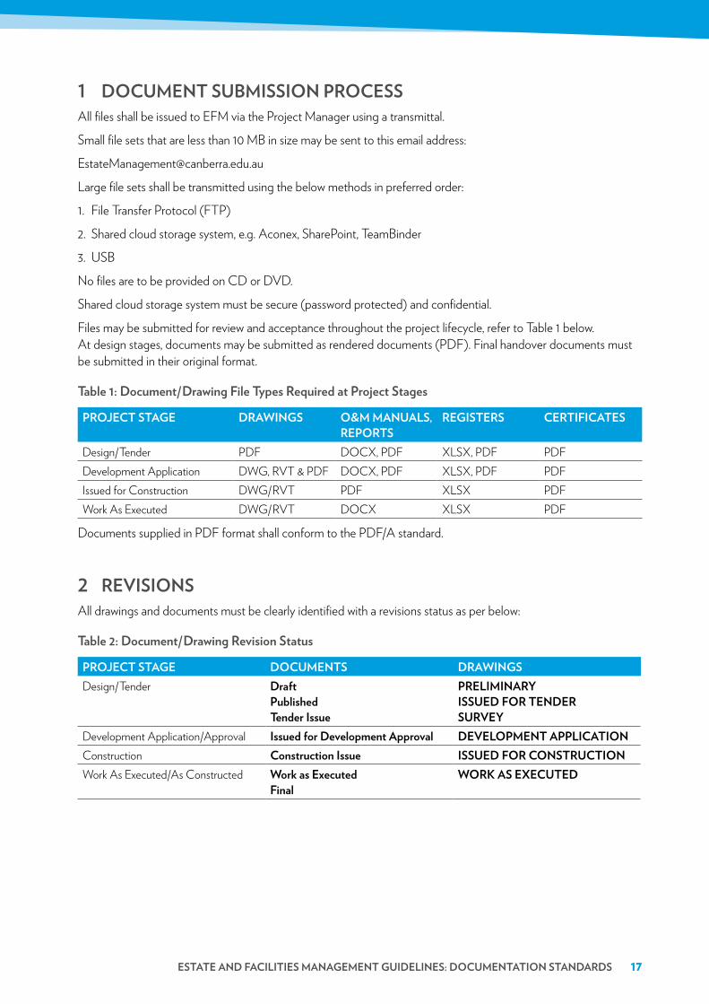
Files may be submitted for review and acceptance throughout the project lifecycle, refer to Table 1 below. At design stages, documents may be submitted as rendered documents (PDF). Final handover documents must be submitted in their original format.
table 1: Document/Drawing File types required at project stages
prOJect stage DraWings O&M ManUals, repOrts
registers certiFicates
Design/Tender PDF DOCX, PDF XLSX, PDF PDFDevelopment Application DWG, RVT & PDF DOCX, PDF XLSX, PDF PDFIssued for Construction DWG/RVT PDF XLSX PDFWork As Executed DWG/RVT DOCX XLSX PDF
Documents supplied in PDF format shall conform to the PDF/A standard.
2 reVisiOnsAll drawings and documents must be clearly identified with a revisions status as per below:
table 2: Document/Drawing revision status
prOJect stage DOcUMents DraWingsDesign/Tender Draft
published tender issue
preliMinarY issUeD FOr tenDer sUrVeY
Development Application/Approval issued for Development approval DeVelOpMent applicatiOnConstruction construction issue issUeD FOr cOnstrUctiOnWork As Executed/As Constructed Work as executed
FinalWOrK as eXecUteD

18 UniVersitY OF canberra / DESIGN POLICY AND STANDARDS
3 asset inFOrMatiOn anD Design reQUireMents
3.1 Design standards and specificationsRefer to the University of Canberra Design Standards as a basis of design of all assets.
3.2 Master planRefer to the University of Canberra Master Plan as a basis of design of all assets.
3.3 asset identification
3.3.1 Building, Level & Room Numbering Standards
Refer to the Standards for the Building, Level and Room Code Standards, Bruce Campus as a basis for determining building, level and room numbers. Requests for numbers shall be emailed to [email protected] and include the proposed floor plan with all internal walls shown.
3.3.2 Other Asset Coding Requirements
UC is currently in the process of developing an asset register to identify all individual assets and equipment. It is expected that the consultant, contractor or service provider will provide an UC Asset Register (UCAR) that will determine the hierarchical levels and processes that will determine the naming convention or identifier that will be referenced in all documentation.
4 sYsteMsIt is important that all documentation and drawings integrate with UC’s systems as per Table 3 to record all asset information, including buildings, infrastructure, services, operations, maintenance, space management, and asset and facilities management.
table 3: Uc asset information systems
sYsteM relateD sOFtWare DOcUMentatiOnBuilding Information Modelling (BIM) System
Autodesk Revit BIM Models
Building (Asset) Management System Optergy, Iviva Asset Register (UCAR)Document Management System SharePoint Operations and Maintenance Manuals,
Certificates, Project Documents (Active Projects), Registers, Reports.
Drawing Management System Autodesk Suite (AutoCAD, Design Review, Revit and Inventor)
CAD Drawings and Models
Geographic Information System (GIS) ESRI ArcGIS MapsRecords Management System HPRM8 (TRIM) Project Documents/Files (Archived
Projects)
estate anD Facilities ManageMent gUiDelines: DOcUMentatiOn stanDarDs 19
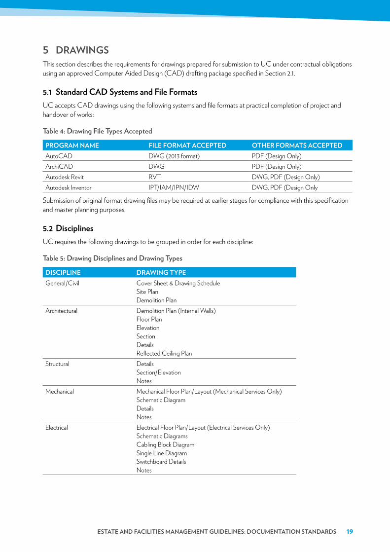
5 DraWingsThis section describes the requirements for drawings prepared for submission to UC under contractual obligations using an approved Computer Aided Design (CAD) drafting package specified in Section 2.1.
5.1 standard caD systems and File FormatsUC accepts CAD drawings using the following systems and file formats at practical completion of project and handover of works:
table 4: Drawing File types accepted
prOgraM naMe File FOrMat accepteD Other FOrMats accepteDAutoCAD DWG (2013 format) PDF (Design Only)ArchiCAD DWG PDF (Design Only)Autodesk Revit RVT DWG, PDF (Design Only)Autodesk Inventor IPT/IAM/IPN/IDW DWG, PDF (Design Only
Submission of original format drawing files may be required at earlier stages for compliance with this specification and master planning purposes.
5.2 DisciplinesUC requires the following drawings to be grouped in order for each discipline:
table 5: Drawing Disciplines and Drawing types
Discipline DraWing tYpeGeneral/Civil Cover Sheet & Drawing Schedule
Site Plan Demolition Plan
Architectural Demolition Plan (Internal Walls) Floor Plan Elevation Section Details Reflected Ceiling Plan
Structural Details Section/Elevation Notes
Mechanical Mechanical Floor Plan/Layout (Mechanical Services Only) Schematic Diagram Details Notes
Electrical Electrical Floor Plan/Layout (Electrical Services Only) Schematic Diagrams Cabling Block Diagram Single Line Diagram Switchboard Details Notes
20 UniVersitY OF canberra / DESIGN POLICY AND STANDARDS
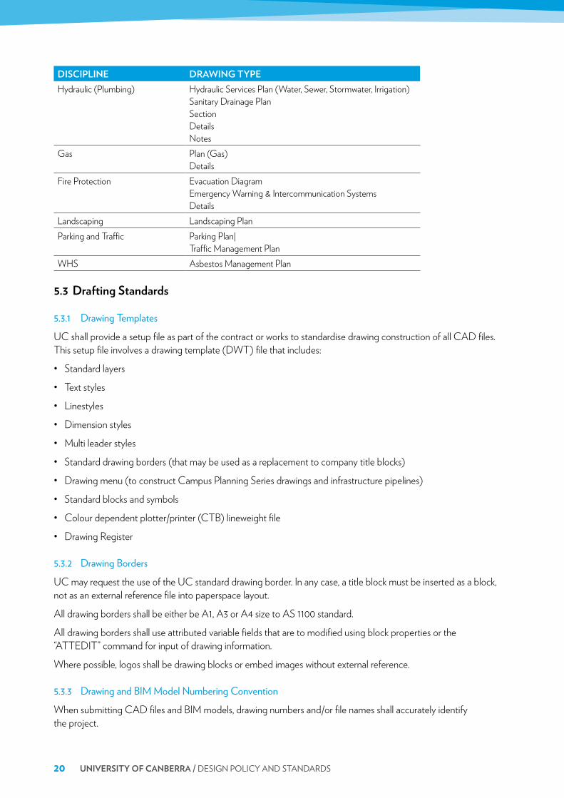
Discipline DraWing tYpeHydraulic (Plumbing) Hydraulic Services Plan (Water, Sewer, Stormwater, Irrigation)
Sanitary Drainage Plan Section Details Notes
Gas Plan (Gas) Details
Fire Protection Evacuation Diagram Emergency Warning & Intercommunication Systems Details
Landscaping Landscaping PlanParking and Traffic Parking Plan|
Traffic Management PlanWHS Asbestos Management Plan
5.3 Drafting standards
5.3.1 Drawing Templates
UC shall provide a setup file as part of the contract or works to standardise drawing construction of all CAD files. This setup file involves a drawing template (DWT) file that includes:
• Standard layers
• Text styles
• Linestyles
• Dimension styles
• Multi leader styles
• Standard drawing borders (that may be used as a replacement to company title blocks)
• Drawing menu (to construct Campus Planning Series drawings and infrastructure pipelines)
• Standard blocks and symbols
• Colour dependent plotter/printer (CTB) lineweight file
• Drawing Register
5.3.2 Drawing Borders
UC may request the use of the UC standard drawing border. In any case, a title block must be inserted as a block, not as an external reference file into paperspace layout.
All drawing borders shall be either be A1, A3 or A4 size to AS 1100 standard.
All drawing borders shall use attributed variable fields that are to modified using block properties or the “ATTEDIT” command for input of drawing information.
Where possible, logos shall be drawing blocks or embed images without external reference.
5.3.3 Drawing and BIM Model Numbering Convention
When submitting CAD files and BIM models, drawing numbers and/or file names shall accurately identify the project.

estate anD Facilities ManageMent gUiDelines: DOcUMentatiOn stanDarDs 21
Drawing number format: [bUilDing nUMber/naMe]-[leVel]-[Discipline]-[iDentiFier]Example: 01-a-ar-2006/001Where the identifier is the internal project/drawing number the consultant/contractor requires.
table 6: Drawing number (bU-lVl-Disc-iD)
bUilDing nUMber (bU)
leVel (lVl) Discipline (Disc) prOJect/DraWing nUMber (iD)
01 A AR 2016/001
Refer to Appendix 1 for Drawing/Document Numbering Convention.
5.3.4 Drawing and BIM Model File Naming Convention
File names of drawings and BIM models shall be named according to the drawing number with the revision included.
Drawing file naming format: [bUilDing nUMber/naMe]-[leVel]-[Discipline]-[iDentiFier]_[reV]Example: 01-a-ar-2006001_a.dwg
01-a-ar-2006001_a.rvtDrawing titles shall be defined in the drawing register and is not required in the file name.
5.3.5 Hybrid File Naming Conventions
All image attachments or external references will be provided using the hybrid file naming convention defined below.
The hybrid file name format:
table 7: hybrid File name Format
DraWing File naMe iMage attachMent eXternal reFerence (X-reF)01-A-AR-2006001_A.dwg 01-a-ar-2006001_a_i01.jpg
01-a-ar-2006001_a_i01.bmp01-a-ar-2006001_a_X01.dwg
Where possible all files shall be zipped on transmittal, embedded or bound to the master drawing file.
5.3.6 Drawing Registers
The Drawing Register contains all finalised versions and identifies all drawings and BIM models. UC shall provide a standard drawing register with the setup file, refer to Section 3.3.1.
Proprietary document transmittals are not acceptable as a replacement to the drawing register unless all metadata listed in Table 8 is included:

22 UniVersitY OF canberra / DESIGN POLICY AND STANDARDS
table 8: Drawing register Metadata requirements
DraWing register MetaData reQUireMentsFile NameDrawing NumberDrawing TitleSheet NumberBuilding NumberBuilding Name (if applicable)Floor LevelExternal Party (Consultant Name)Client NameDisciplineStatus (Reason for Issue)Asset Number(s)Revision NumberDrawn DateDate of Original IssueDate of Previous/Last IssueAuthor (Drawn)DesignerDesign VerificationProject Manager (Internal & External)Original Sheet Size
5.3.7 Drawing Scales, Units and System Variables
All drawings will be drawn to actual (1:1) scale in model space and presented to following standard scales (reduction ratios) in paper space.
table 9: standard Drawing scales
DraWing tYpe preFerreD scaleDetails/Sections 1:10, 1:20, 1:25, 1:50Floor Plans 1:100, 1:200Building Site Plans 1:200, 1:500, 1:1000Campus Site Plan/Location Plan 1:1000, 1:2500
The units of measurement will be as follows:
• 1 unit = 1 metre for site plans, survey plans, traffic management plans
• 1 unit = 1 millimetre for building floor plans, elevations, sections, details, and drawing borders
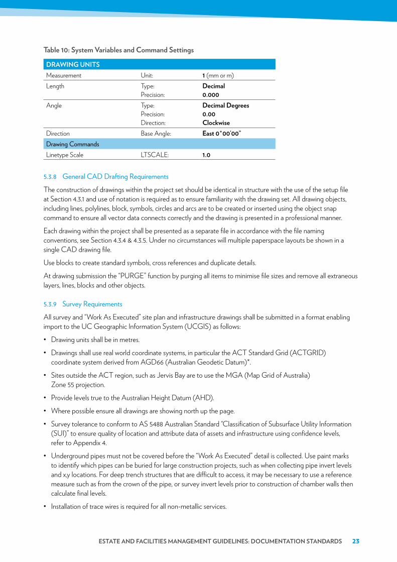
The following system variables or command settings (in particular for AutoCAD) are required to be set for all drawings:
estate anD Facilities ManageMent gUiDelines: DOcUMentatiOn stanDarDs 23
table 10: system Variables and command settings
DraWing UnitsMeasurement Unit: 1 (mm or m)Length Type:
Precision:Decimal 0.000
Angle Type: Precision: Direction:
Decimal Degrees 0.00 clockwise
Direction Base Angle: east 0˚00’00”Drawing CommandsLinetype Scale LTSCALE: 1.0
5.3.8 General CAD Drafting Requirements
The construction of drawings within the project set should be identical in structure with the use of the setup file at Section 4.3.1 and use of notation is required as to ensure familiarity with the drawing set. All drawing objects, including lines, polylines, block, symbols, circles and arcs are to be created or inserted using the object snap command to ensure all vector data connects correctly and the drawing is presented in a professional manner.
Each drawing within the project shall be presented as a separate file in accordance with the file naming conventions, see Section 4.3.4 & 4.3.5. Under no circumstances will multiple paperspace layouts be shown in a single CAD drawing file.
Use blocks to create standard symbols, cross references and duplicate details.
At drawing submission the “PURGE” function by purging all items to minimise file sizes and remove all extraneous layers, lines, blocks and other objects.
5.3.9 Survey Requirements
All survey and “Work As Executed” site plan and infrastructure drawings shall be submitted in a format enabling import to the UC Geographic Information System (UCGIS) as follows:
• Drawing units shall be in metres.
• Drawings shall use real world coordinate systems, in particular the ACT Standard Grid (ACTGRID) coordinate system derived from AGD66 (Australian Geodetic Datum)*.
• Sites outside the ACT region, such as Jervis Bay are to use the MGA (Map Grid of Australia) Zone 55 projection.
• Provide levels true to the Australian Height Datum (AHD).
• Where possible ensure all drawings are showing north up the page.
• Survey tolerance to conform to AS 5488 Australian Standard “Classification of Subsurface Utility Information (SUI)” to ensure quality of location and attribute data of assets and infrastructure using confidence levels, refer to Appendix 4.
• Underground pipes must not be covered before the “Work As Executed” detail is collected. Use paint marks to identify which pipes can be buried for large construction projects, such as when collecting pipe invert levels and x,y locations. For deep trench structures that are difficult to access, it may be necessary to use a reference measure such as from the crown of the pipe, or survey invert levels prior to construction of chamber walls then calculate final levels.
• Installation of trace wires is required for all non-metallic services.
24 UniVersitY OF canberra / DESIGN POLICY AND STANDARDS
• Provide survey attribute data to the requirements of Appendix 5 and include coordinate tables in drawings for newly constructed manholes, sumps, hydrants, valves, meters, sprinkler points, trees etc.
• Use the “Drawing Menu” that defines linestyles, colours and attributes (see Appendix 5) to identify all services shown. Provide a legend of all services and symbols.
• If a CCTV inspection was carried out, provide a digital video file and reference to drawing using maintenance hole reference points as an example, and advise of any defects to Estate and Facilities Management.
*Source: http://www.planning.act.gov.au/tools_resources/survey-data-maps/surveying_data/surveyors_information/coordinate_system/act_standard_grid_parameters
5.4 biM standards
5.4.1 BIM Project Templates
UC shall provide a setup file as part of the contract or works to standardise BIM model construction. This setup file involves a Revit template (RTE) file that includes:
• Revit project file (RVT)
• Text styles
• Object naming conventions
• Object attribute parameters
5.4.2 BIM Model Development Methodology
Models may be created and developed using a stage process that is suitable to support the required outcomes.
UC suggests the adoption of the NATSPEC National BIM Guide and Project BIM Brief Template* that defines the procedures and requirements to implement BIM on a project.
The level of development (LOD) as defined in the NATSPEC National BIM Guide of the BIM model shall be defined in a project specific BIM Management Plan (BMP) or contractual agreement.
*Source: http://bim.natspec.org/documents/natspec-national-bim-guide & http://bim.natspec.org/images/NATSPEC_Documents/NATSPEC_National_BIM_Guide_v1.0_and_PBB_v2.0.zip
5.4.3 BIM Model Exchange and Ownership
Due to the complexity and specialisation in BIM models, UC requests a model exchange between project team members at “Work As Executed” stage dependant on project design requirements.
Ownership of the models shall be defined in the BMP/contractual agreement. It is intended that the BIM model will become the intellectual property of the University of Canberra.
Minimum requirement for BIM models provided to UC are to be 3D model standard, with a view to be provided with 4D and 5D BIM subject to proprietary information contained within these models.

estate anD Facilities ManageMent gUiDelines: DOcUMentatiOn stanDarDs 25
6 OperatiOns anD Maintenance ManUalsOperations and maintenance (O&M) manuals shall be submitted for all assets including design and construction projects, services installations and building elements with specific maintenance requirements.
6.1 Operations and Maintenance Manual templatesUC shall provide a setup file as part of the contract or works to standardise the preparation of O&M manuals and associated documents. This setup file involves a zip file that includes:
• Asset Register (Excel spreadsheet)• Asset Data Sheet (TBA)• O&M Manual Template (Word document)
− Cover Sheet − Table of Contents (include figures and tables) − Document authorisation and revision control − Section 1 – Building/Facility Specific Information
· High level description of facility (Basis of design, operation and control) · High level description of process/function · Hazards identification
− Section 2 – Operations Manual · Detailed description of operations process · Operating Procedures · Process flows (include flow charts or reference to drawings) · Operational monitoring and control (e.g. Modes of operation, sequences, interlocks and alarms) · Troubleshooting Guides · Technical data sheets
− Section 3 – Maintenance Manual · Maintenance Plans/Schedules · Assets/Components maintenance plans · Recommended Spare Parts/Spare Parts schedule · Work Method Statements (include JSA, JSEA, SWI, Safety Procedures where available)
− Section 4 – Commissioning · Witness testing and training · Commissioning/Asset Handover forms · List of suppliers
− Appendicies · Appendix 1 – Project Details · Appendix 2 – List of Suppliers · Appendix 3 – Drawing List (link to Building Management System/SharePoint)
• Checklist
The O&M manuals must contain these separate sections as a minimum to ensure correct operating procedures of assets, ensure specific maintenance tasks are carried out and detailed technical information is provided for further development.

26 UniVersitY OF canberra / DESIGN POLICY AND STANDARDS
6.2 Document numbering conventionWhen submitting O&M manuals and associated documentation, all documents shall be accurately identified within the project.
Document number format: [bUilDing nUMber/naMe]-[leVel]-[Discipline]-[iDentiFier]Example: 01-a-ar-O&M001Where the identifier is the internal project/document number or name the consultant/contractor requires.
table 11: Document number (bU-lVl-Disc-iD)
bUilDing nUMber (bU) leVel (lVl) Discipline (Disc) iDentiFier (iD)01 A AR O&M001
Refer to Appendix 1 for Drawing/Document Numbering Convention.
6.3 Document File naming conventionFile names of all documents shall be named according to the document number with the revision/version and title included.
Drawing file naming format: [bUilDing nUMber/naMe]-[leVel]-[Discipline]-[iDentiFier]-[title]_[reV]Example: 01-a-ar-O&M001 building 1 O&M Manual_a.docx
6.4 Operations and Maintenance Manual submission requirementsO&M manuals and associated documents shall be submitted in accordance with document submission process as outlined in Section 1. Table 12 below also defines hardcopy documentation requirements to be phased out by 2020.

estate anD Facilities ManageMent gUiDelines: DOcUMentatiOn stanDarDs 27
table 12: hardcopy/softcopy Documentation submission
prOJect tYpe
harDcOpY sOFtcOpYQtY. sUbMissiOn stage %
cOMpleteQtY. sUbMissiOn stage %
cOMpleteExisting Refurbishment
1 UC Asset Register 30 1 UC Asset Register 301 O&M Manual handover
at Date of practical completion
90 1 O&M Manual handover at Date of practical completion
90
2 All documentation handover (including final O&M Manual)
Four (4) weeks after practical completion
100 1 All documentation handover (including final O&M Manual)
Four (4) weeks after practical completion
100
2 All documentation handover (including final O&M Manual)
Defects liability period
100 1 All documentation handover (including final O&M Manual)
Defects liability period
100
New Build Projects
1 UC Asset Register 30 1 UC Asset Register 301 O&M Manual handover
at Date of practical completion
90 1 O&M Manual handover at Date of practical completion
90
2 All documentation handover (including final O&M Manual)
Four (4) weeks after practical completion
100 1 All documentation handover (including final O&M Manual)
Four (4) weeks after practical completion
100
2 All documentation handover (including final O&M Manual)
Defects liability period
100 1 All documentation handover (including final O&M Manual)
Defects liability period
100
7 technical repOrts, speciFicatiOns, certiFicates anD Warranties
Detailed technical reports, specifications, certificates and warranties shall be submitted depending on the asset or service provided. A manufacturer or suitably qualified consultant/contractor may provide technical information that can be used for:
• Operations and maintenance (to be incorporated into O&M manuals)
• Master planning
• Asset condition assessments
• Compliance
• Where possible use cross references to existing documentation provided, in particular to drawings, and reference to asset identification/numbering conventions as described in Section 3.3.

28 UniVersitY OF canberra / DESIGN POLICY AND STANDARDS
7.1 Document templatesIt is acceptable to use manufacturer’s or consultants/contractors templates. If preparing or updating a corporate report, it is preferred that the document provided is used or at least used as a reference. Existing documents can be requested under RFI (Request for Information) or Technical Query (TQ) to [email protected] or the relevant UC Project Manager/requestor.
7.2 technical specificationsTechnical specifications shall contain the following information:
• A technical description of the system installed, written to ensure that UC’s staff fully understand the scope and facilities provided.
• The system’s function, normal operating characteristics, and limiting conditions.
• A technical description of the mode of operation of the systems installed and final setup that meets design performance.
• Schedules (system by system) of equipment, stating locations, duties, performance figures and dates of manufacture.
• Unique asset identification/code number for each item of equipment installed, cross referenced to the diagrammatic drawings and schedules, including spare part schedule.
• Manufacturers’ technical literature for equipment installed, assembled specifically for the project or service, excluding irrelevant matter. Product data sheets shall clearly identify specific products and component parts used in the installation, and data applicable to the installation.
• Supplements to product data shall illustrate relations of component parts.
7.3 certificatesCertification shall contain the following information for each system installed or service provided:
• Certificates and registrations from authorities
• Product certification
• Service provision, e.g. Removal of Asbestos
• Commissioning test results
• Commissioning test reports
• Safety Data Sheets
7.4 WarrantiesManufacturers’ warranties shall be provided as part of the O&M manuals for all systems and any services with provision to risk and/or safety.
8 cOMMissiOning anD hanDOVer OF DOcUMentatiOnTo be advised at a later date, proposed documents include:
• Practical Completion Certificate
• Project Handover Deliverables Checklist

appenDiX 1 – DraWing & DOcUMent nUMbering cOnVentiOn 29
APPENDIX 1 – DRAWING & DOCUMENT NUMBERING CONVENTION Drawing/Document number = bU-lVl-Disc-iDbUilDing nUMber (bU) leVel (lVl) Discipline (Disc) prOJect/
DraWing nUMber (iD)
UC Campus, Grounds A Level A AR Architectural (e.g.) 2016-00101 Building 1 (Chancellery) B Level B CV Civil02 Building 2 C Level C EL Electrical03 Building 3 D Level D FP Fire Protection04 Building 4 (Gym) E Level E GA Gas05 Building 5 X Multiple Areas GN General06 Building 6 HY Hydraulic07 Building 7 LA Landscaping08 Building 8 (Library) ME Mechanical09 Building 9 SU Survey10 Building 10 ST Structural11 Building 11 TF Parking & Traffic12 Building 1213 Building 1313a Building 13a13b Building 13b14 Building 14 (Boiler House)15 Building 1516a Building 16a16b Building 16b16c Building 16c17 Building 1718 Building 1819 Building 1920 Building 2021 Building 21 (Cooinda Hut)22 Building 22 (UCIC)23 Building 23 (UCIC)24 Building 24 (NATSEM)25 Building 25 (INSPIRE Centre)26 Building 26 (Scrivener)27 Building 27 (Laboratory)
30 UniVersitY OF canberra / DESIGN POLICY AND STANDARDS
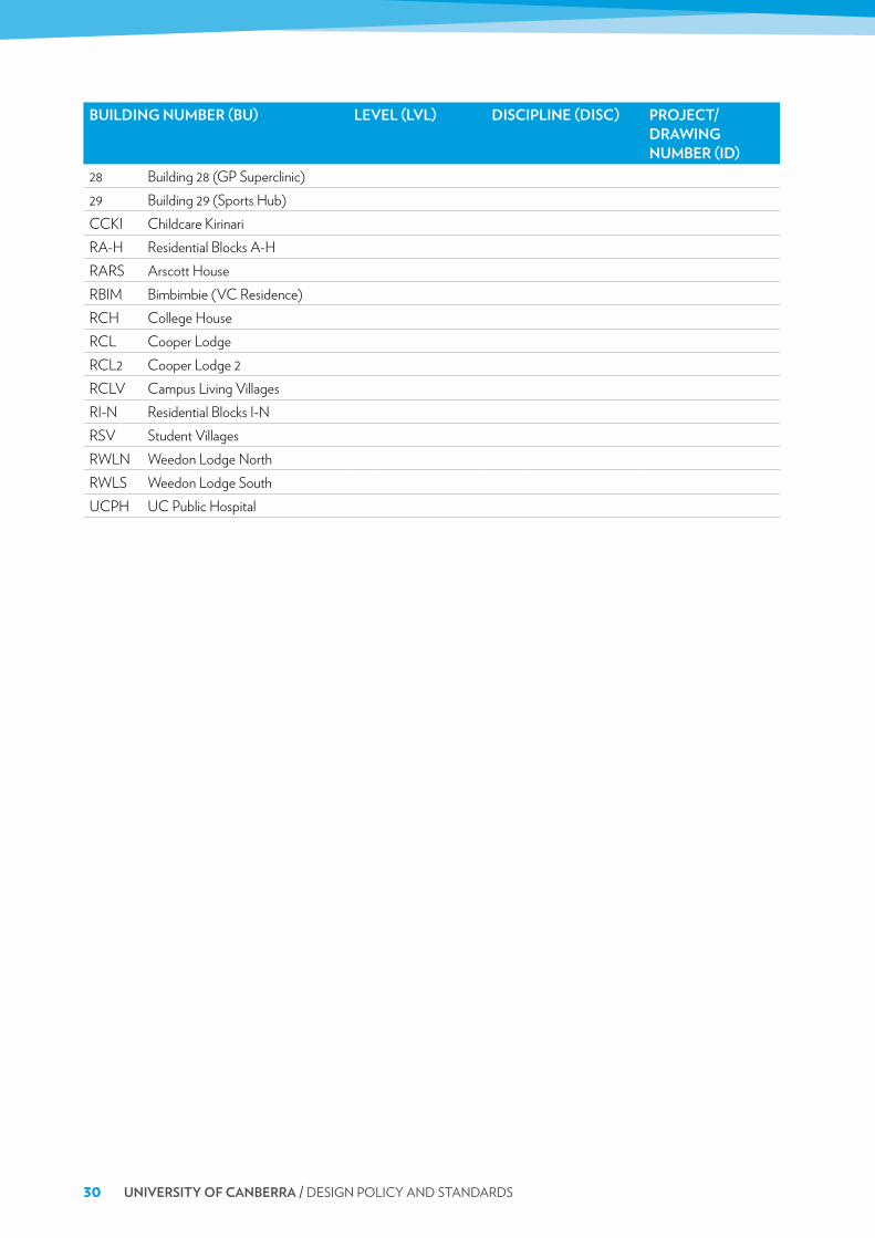
bUilDing nUMber (bU) leVel (lVl) Discipline (Disc) prOJect/DraWing nUMber (iD)
28 Building 28 (GP Superclinic)29 Building 29 (Sports Hub)CCKI Childcare KirinariRA-H Residential Blocks A-HRARS Arscott HouseRBIM Bimbimbie (VC Residence)RCH College HouseRCL Cooper LodgeRCL2 Cooper Lodge 2RCLV Campus Living VillagesRI-N Residential Blocks I-NRSV Student VillagesRWLN Weedon Lodge NorthRWLS Weedon Lodge SouthUCPH UC Public Hospital

appenDiX 2 – cOlOUr stanDarDs 31
APPENDIX 2 – COLOUR STANDARDSlaYer cOlOUr nUMber
(aUtOcaD)lineWeight pen cOlOUr pen nUMber
Red 1 0.35mm Black 7Yellow 2 1.00mm Black 7Green 3 0.50mm Black 7Cyan 4 0.70mm Black 7Blue 5 Black 7Magenta 6 0.18mm Black 7White 7 0.25mm Black 7Dark Grey 8 0.13mm Black 7Light Grey 9 0.09mm Black 7

32 UniVersitY OF canberra / DESIGN POLICY AND STANDARDS
APPENDIX 3 – LAYER STANDARDSThe standard layer name convention shown below shall be used in the preparation of all UC CAD drawings. The standard layer names are defined in the standard drawing template, UC.dwt.
Additional layer names are accepted based on the American Institute of Architects CAD Layer Guidelines or using descriptive layer names as per below example:
example: a-25-external Wallwhere:
• A = Architectural• 25 = 0.25mm lineweight• External Wall = Walls with an external façade (Descriptive)
laYer naMe cOlOUr linetYpe lineWeight plOt Details0 White -7 Continuous Default TRUE Internal Use OnlyA-13-ABOVE Grey - 8 HIDDENX2 0.13mm TRUE
ARCHITECTURAL
A-13-BELOW Grey -8 HIDDENX2 0.13mm TRUEA-13-FITTINGS Grey - 8 Continuous 0.13mm TRUEA-13-FURNITURE White -7 Continuous 0.13mm TRUEA-13-HIDDEN Grey - 8 HIDDENX2 0.13mm TRUEA-13-JOINERY White -7 Continuous 0.13mm TRUEA-13-KITCHEN Grey - 8 Continuous 0.13mm TRUEA-13-LIFT Grey - 8 Continuous 0.13mm TRUEA-13-SANITARY Grey - 8 Continuous 0.13mm TRUEA-13-STAIRS & RAMPS Grey - 8 Continuous 0.13mm TRUEA-13-WINDOW-INTERNAL Grey - 8 Continuous 0.13mm TRUEA-18-DOOR Magenta - 6 Continuous 0.18mm TRUEA-18-DOOR-ROLLER Magenta - 6 Continuous 0.18mm TRUEA-18-WALL-HIDDEN Magenta - 6 Continuous 0.18mm TRUEA-18-WALL-INTERNAL Magenta - 6 Continuous 0.18mm TRUEA-18-WINDOW Magenta - 6 Continuous 0.18mm TRUEA-25-WALL-EXTERNAL White -7 Continuous 0.25mm TRUEA-35-DEMO 10 Continuous 0.35mm TRUEA-50-NEW WORKS 70 Continuous 0.50mm TRUEC-09- Grey - 9 Continuous 0.09mm TRUE
ALL DATA AND COMMUNICATION SERVICES
C-100- Yellow - 2 Continuous 1.00mm TRUEC-13- Grey - 8 Continuous 0.13mm TRUEC-18- Magenta - 6 Continuous 0.18mm TRUEC-25- White -7 Continuous 0.25mm TRUEC-35- 10 Continuous 0.35mm TRUEC-50- Green - 3 Continuous 0.50mm TRUEC-70- Cyan - 4 Continuous 0.70mm TRUEDefpoints White -7 Continuous Default FALSE
appenDiX 3 – laYer stanDarDs 33
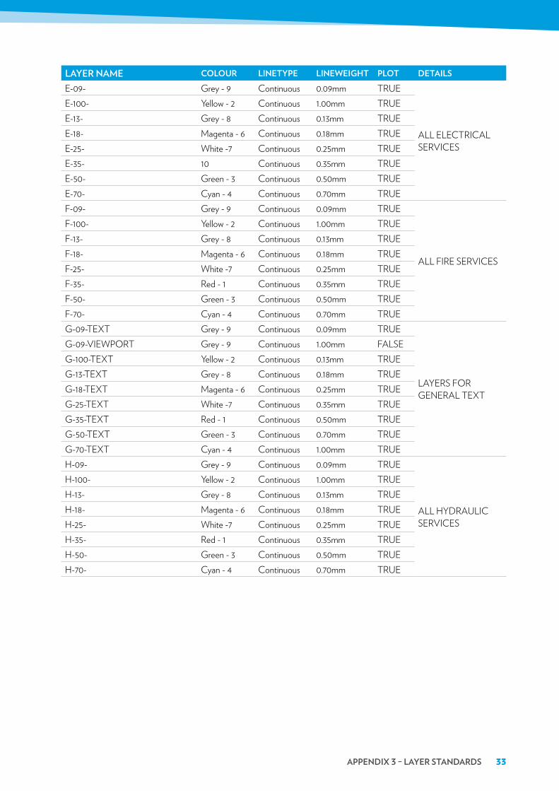
laYer naMe cOlOUr linetYpe lineWeight plOt DetailsE-09- Grey - 9 Continuous 0.09mm TRUE
ALL ELECTRICAL SERVICES
E-100- Yellow - 2 Continuous 1.00mm TRUEE-13- Grey - 8 Continuous 0.13mm TRUEE-18- Magenta - 6 Continuous 0.18mm TRUEE-25- White -7 Continuous 0.25mm TRUEE-35- 10 Continuous 0.35mm TRUEE-50- Green - 3 Continuous 0.50mm TRUEE-70- Cyan - 4 Continuous 0.70mm TRUEF-09- Grey - 9 Continuous 0.09mm TRUE
ALL FIRE SERVICES
F-100- Yellow - 2 Continuous 1.00mm TRUEF-13- Grey - 8 Continuous 0.13mm TRUEF-18- Magenta - 6 Continuous 0.18mm TRUEF-25- White -7 Continuous 0.25mm TRUEF-35- Red - 1 Continuous 0.35mm TRUEF-50- Green - 3 Continuous 0.50mm TRUEF-70- Cyan - 4 Continuous 0.70mm TRUEG-09-TEXT Grey - 9 Continuous 0.09mm TRUE
LAYERS FOR GENERAL TEXT
G-09-VIEWPORT Grey - 9 Continuous 1.00mm FALSEG-100-TEXT Yellow - 2 Continuous 0.13mm TRUEG-13-TEXT Grey - 8 Continuous 0.18mm TRUEG-18-TEXT Magenta - 6 Continuous 0.25mm TRUEG-25-TEXT White -7 Continuous 0.35mm TRUEG-35-TEXT Red - 1 Continuous 0.50mm TRUEG-50-TEXT Green - 3 Continuous 0.70mm TRUEG-70-TEXT Cyan - 4 Continuous 1.00mm TRUEH-09- Grey - 9 Continuous 0.09mm TRUE
ALL HYDRAULIC SERVICES
H-100- Yellow - 2 Continuous 1.00mm TRUEH-13- Grey - 8 Continuous 0.13mm TRUEH-18- Magenta - 6 Continuous 0.18mm TRUEH-25- White -7 Continuous 0.25mm TRUEH-35- Red - 1 Continuous 0.35mm TRUEH-50- Green - 3 Continuous 0.50mm TRUEH-70- Cyan - 4 Continuous 0.70mm TRUE

34 UniVersitY OF canberra / DESIGN POLICY AND STANDARDS
laYer naMe cOlOUr linetYpe lineWeight plOt DetailsL-09- Grey - 9 Continuous 0.09mm TRUE
ALL LANDSCAPING
L-100- Yellow - 2 Continuous 1.00mm TRUEL-13- Grey - 8 Continuous 0.13mm TRUEL-13-FOOTPATH Grey - 8 Continuous 0.13mm TRUEL-18- Magenta - 6 Continuous 0.18mm TRUEL-18-FENCE Magenta - 6 Continuous 0.18mm TRUEL-18-RETAINING WALL Magenta - 6 Continuous 0.18mm TRUEL-25- White -7 Continuous 0.25mm TRUEL-25-OVAL OUTLINE White -7 Continuous 0.25mm TRUEL-35- Red - 1 Continuous 0.35mm TRUEL-50- Green - 3 Continuous 0.50mm TRUEL-50-GARDEN EDGE Green - 3 Continuous 0.50mm TRUEL-50-TREES Green - 3 Continuous 0.50mm TRUEL-70- Cyan - 4 Continuous 0.70mm TRUEL-70-PONDS & LAKE Cyan - 4 Continuous 0.70mm TRUEM-09- Grey - 9 Continuous 0.09mm TRUE
ALL MECHANICAL SERVICES
M-100- Yellow - 2 Continuous 1.00mm TRUEM-13- Grey - 8 Continuous 0.13mm TRUEM-18- Magenta - 6 Continuous 0.18mm TRUEM-25- White -7 Continuous 0.25mm TRUEM-35- Red - 1 Continuous 0.35mm TRUEM-50- Green - 3 Continuous 0.50mm TRUEM-70- Cyan - 4 Continuous 0.70mm TRUES-09- Grey - 9 Continuous 0.09mm TRUE
ALL STRUCTURAL
S-100- Yellow - 2 Continuous 1.00mm TRUES-13- Grey-8 Continuous 0.13mm TRUES-13-COLUMN CENTRE GRID Grey-8 Continuous 0.13mm TRUES-18- Magenta - 6 Continuous 0.18mm TRUES-18-COLUMN GRID TEXT Magenta - 6 Continuous 0.18mm TRUES-25- White -7 Continuous 0.25mm TRUES-25-COLUMN White -7 Continuous 0.25mm TRUES-35- Red - 1 Continuous 0.35mm TRUES-50- Green - 3 Continuous 0.50mm TRUES-70- Cyan - 4 Continuous 0.70mm TRUE
appenDiX 3 – laYer stanDarDs 35
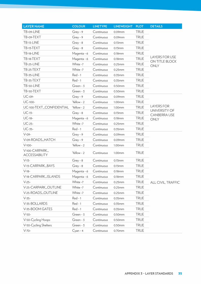
laYer naMe cOlOUr linetYpe lineWeight plOt DetailsTB-09-LINE Grey - 9 Continuous 0.09mm TRUE
LAYERS FOR USE ON TITLE BLOCK ONLY
TB-09-TEXT Grey - 9 Continuous 0.09mm TRUETB-13-LINE Grey - 8 Continuous 0.13mm TRUETB-13-TEXT Grey - 8 Continuous 0.13mm TRUETB-18-LINE Magenta - 6 Continuous 0.18mm TRUETB-18-TEXT Magenta - 6 Continuous 0.18mm TRUETB-25-LINE White -7 Continuous 0.25mm TRUETB-25-TEXT White -7 Continuous 0.25mm TRUETB-35-LINE Red - 1 Continuous 0.35mm TRUETB-35-TEXT Red - 1 Continuous 0.35mm TRUETB-50-LINE Green - 3 Continuous 0.50mm TRUETB-50-TEXT Green - 3 Continuous 0.50mm TRUEUC-09- Grey - 9 Continuous 0.09mm TRUE
LAYERS FOR UNIVERSITY OF CANBERRA USE ONLY
UC-100- Yellow - 2 Continuous 1.00mm TRUEUC-100-TEXT_CONFIDENTIAL Yellow - 2 Continuous 1.00mm TRUEUC-13- Grey - 8 Continuous 0.13mm TRUEUC-18- Magenta - 6 Continuous 0.18mm TRUEUC-25- White -7 Continuous 0.25mm TRUEUC-35- Red - 1 Continuous 0.35mm TRUEV-09- Grey - 9 Continuous 0.09mm TRUE
ALL CIVIL, TRAFFIC
V-09-ROADS_HATCH Grey - 9 Continuous 0.09mm TRUEV-100- Yellow - 2 Continuous 1.00mm TRUEV-100-CARPARK_ACCESSABILITY Yellow - 2 Continuous 1.00mm TRUE
V-13- Grey - 8 Continuous 0.13mm TRUEV-13-CARPARK_BAYS Grey - 8 Continuous 0.13mm TRUEV-18- Magenta - 6 Continuous 0.18mm TRUEV-18-CARPARK_ISLANDS Magenta - 6 Continuous 0.18mm TRUEV-25- White -7 Continuous 0.25mm TRUEV-25-CARPARK_OUTLINE White -7 Continuous 0.25mm TRUEV-25-ROADS_OUTLINE White -7 Continuous 0.25mm TRUEV-35- Red - 1 Continuous 0.35mm TRUEV-35-BOLLARDS Red - 1 Continuous 0.35mm TRUEV-35-BOOM GATES Red - 1 Continuous 0.35mm TRUEV-50- Green - 3 Continuous 0.50mm TRUEV-50-Cycling Hoops Green - 3 Continuous 0.50mm TRUEV-50-Cycling Shelters Green - 3 Continuous 0.50mm TRUEV-70- Cyan - 4 Continuous 0.70mm TRUE
36 UniVersitY OF canberra / DESIGN POLICY AND STANDARDS
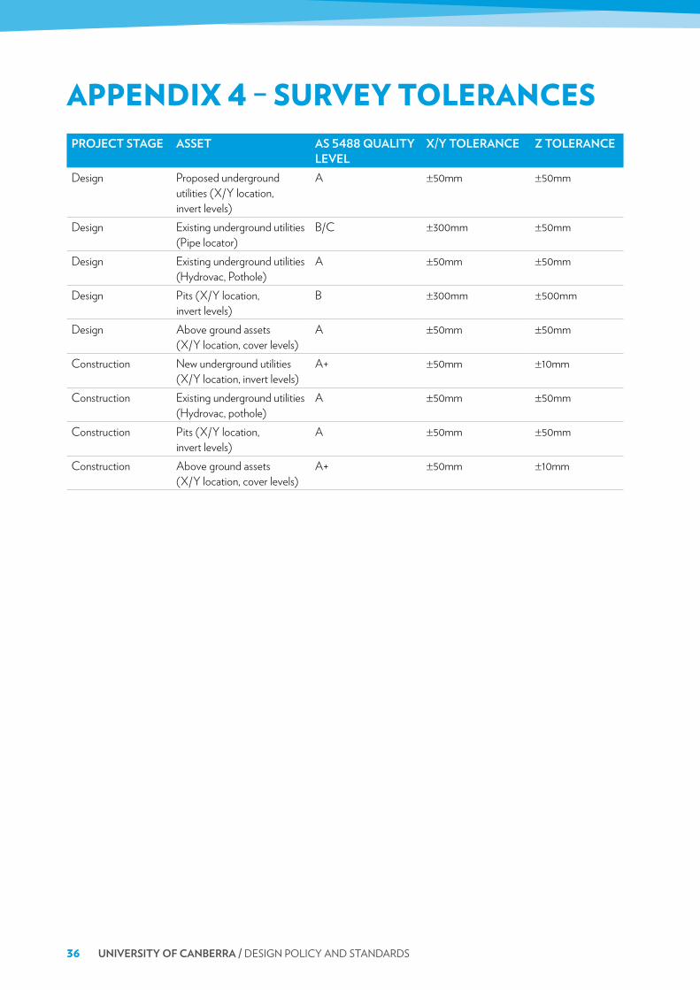
APPENDIX 4 – SURVEY TOLERANCESprOJect stage asset as 5488 QUalitY
leVelX/Y tOlerance Z tOlerance
Design Proposed underground utilities (X/Y location, invert levels)
A ±50mm ±50mm
Design Existing underground utilities (Pipe locator)
B/C ±300mm ±50mm
Design Existing underground utilities (Hydrovac, Pothole)
A ±50mm ±50mm
Design Pits (X/Y location, invert levels)
B ±300mm ±500mm
Design Above ground assets (X/Y location, cover levels)
A ±50mm ±50mm
Construction New underground utilities (X/Y location, invert levels)
A+ ±50mm ±10mm
Construction Existing underground utilities (Hydrovac, pothole)
A ±50mm ±50mm
Construction Pits (X/Y location, invert levels)
A ±50mm ±50mm
Construction Above ground assets (X/Y location, cover levels)
A+ ±50mm ±10mm

appenDiX 5 – sUrVeY Data reQUireMents 37
APPENDIX 5 – SURVEY DATA REQUIREMENTSattribUte DescriptiOn Data OptiOn ManDatOrYAssetID Used as an identifier to describe the asset
(to be used to reference to the BMS/Works Management System)
No
ConstructionDate/CommissioningDate/ConstructionYear
Used to identify the date of construction or age of asset.
Yes
DataSource The data source used to identify the asset. Work As Executed Drawing Survey (where no Work As Executed Drawing) Design Drawing Existing Drawing Field Check Unknown
Yes
DrawingNumber The drawing number, job number or identification used to reference the data source.
Yes
Owner Owner of a particular asset University of Canberra ACT Government ActewAGL Icon Water iQon Telstra Private
No
LifecycleStatus The functional, operational or existential status of the asset at the time the drawing/survey is submitted.
Active Abandoned Designed/Planned Removed
Yes
PositionSource The spatial accuracy, position or location of the asset.
Work As Executed Drawing DGPS Assumed
Easting* Survey Easting Coordinate Position (ACT Stromlo Grid)
Northing* Survey Northing Coordinate Position (ACT Stromlo Grid)
*Point features only

38 UniVersitY OF canberra / DESIGN POLICY AND STANDARDS
FeatUre class (asset naMe/laYer)
attribUte DescriptiOn attribUtes ManDatOrY
Buildings BuildingNumber BuildingName Levels ConstructionYear GFA UFA
Building Number Building Name, e.g. Number of Levels, e.g. 4 (A-D) Year Building Constructed, e.g. 1999 Gross Floor Area Usable Floor Area
Y N Y N N N
ConstructionZone ConstructionStartDate ConstructionFinishDate
Construction Start Date Construction Finish Date
Parking ParkingNumber ParkingName ParkingType ParkingSpaces
Parking Number, e.g. P1 Parking Name, e.g. Parking Type, e.g. Number of Spaces, e.g.
N N Y Y
Landuse Landuse Landuse as per 2012 Campus Master Plan
Bimbimbie Campus Community Concourse Health Precinct Heartland Innovation Park Sporting Commons University Green University Hill Village
Y
GasMeter MeterNumber
Manufacturer Model Size
Meter Number (ActewAGL Billing Number) Manufacturer Model Name/Number Meter Size
Y Y Y Y
Valve SubType Operation Size
Type of Valve Operation, e.g. Manual or Automatic Valve Size
Y Y Y
Main SubType Material Diameter InvertLevel1 InvertLevel2
Type of Main Pipe Material Pipe Diameter Survey Invert Level (AHD in metres) at highest end of pipe Survey Invert Level (AHD in metres) at lowest end of pipe
Y Y Y Y Y
Sewer

appenDiX 5 – sUrVeY Data reQUireMents 39
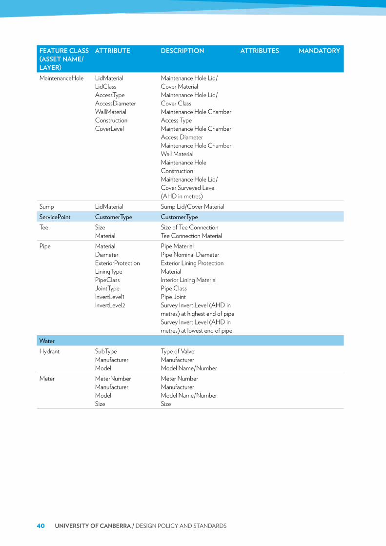
FeatUre class (asset naMe/laYer)
attribUte DescriptiOn attribUtes ManDatOrY
MaintenanceHole LidMaterial LidClass AccessType AccessDiameter WallMaterial Construction CoverLevel
Maintenance Hole Lid/ Cover Material Maintenance Hole Lid/ Cover Class Maintenance Hole Chamber Access Type Maintenance Hole Chamber Access Diameter Maintenance Hole Chamber Wall Material Maintenance Hole Construction Maintenance Hole Lid/ Cover Surveyed Level (AHD in metres)
ServicePoint CustomerType CustomerTypeTee Size
MaterialSize of Tee Connection Tee Connection Material
GravityMain Material Diameter ExteriorProtection LiningType PipeClass JointType InvertLevel1 InvertLevel2
Pipe Material Pipe Nominal Diameter Exterior Lining Protection Material Interior Lining Material Pipe Class Pipe Joint Survey Invert Level (AHD in metres) at highest end of pipe Survey Invert Level (AHD in metres) at lowest end of pipe
ServiceLine SewageType Material Diameter LiningType PipeClass JointType InvertLevel
Type of Sewage Pipe Material Pipe Diameter Internal or External Lining Material Pipe Class Pipe Joint Survey Invert Level (AHD in metres)
Stormwater
40 UniVersitY OF canberra / DESIGN POLICY AND STANDARDS
FeatUre class (asset naMe/laYer)
attribUte DescriptiOn attribUtes ManDatOrY
MaintenanceHole LidMaterial LidClass AccessType AccessDiameter WallMaterial Construction CoverLevel
Maintenance Hole Lid/ Cover Material Maintenance Hole Lid/ Cover Class Maintenance Hole Chamber Access Type Maintenance Hole Chamber Access Diameter Maintenance Hole Chamber Wall Material Maintenance Hole Construction Maintenance Hole Lid/ Cover Surveyed Level (AHD in metres)
Sump LidMaterial Sump Lid/Cover MaterialServicePoint CustomerType CustomerTypeTee Size
MaterialSize of Tee Connection Tee Connection Material
Pipe Material Diameter ExteriorProtection LiningType PipeClass JointType InvertLevel1 InvertLevel2
Pipe Material Pipe Nominal Diameter Exterior Lining Protection Material Interior Lining Material Pipe Class Pipe Joint Survey Invert Level (AHD in metres) at highest end of pipe Survey Invert Level (AHD in metres) at lowest end of pipe
WaterHydrant SubType
Manufacturer Model
Type of Valve Manufacturer Model Name/Number
Meter MeterNumber Manufacturer Model Size
Meter Number Manufacturer Model Name/Number Size
appenDiX 5 – sUrVeY Data reQUireMents 41
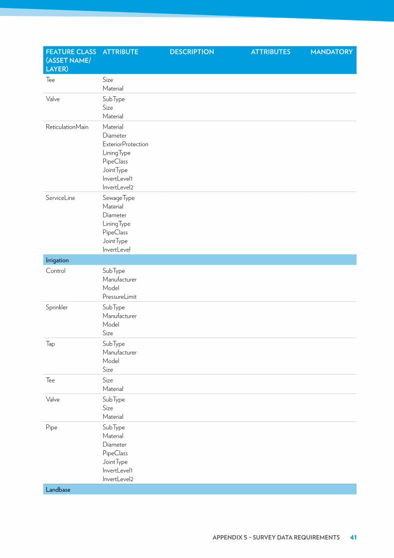
FeatUre class (asset naMe/laYer)
attribUte DescriptiOn attribUtes ManDatOrY
Tee Size Material
Valve SubType Size Material
ReticulationMain Material Diameter ExteriorProtection LiningType PipeClass JointType InvertLevel1 InvertLevel2
ServiceLine SewageType Material Diameter LiningType PipeClass JointType InvertLevel
IrrigationControl SubType
Manufacturer Model PressureLimit
Sprinkler SubType Manufacturer Model Size
Tap SubType Manufacturer Model Size
Tee Size Material
Valve SubType Size Material
Pipe SubType Material Diameter PipeClass JointType InvertLevel1 InvertLevel2
Landbase

42 UniVersitY OF canberra / DESIGN POLICY AND STANDARDS
FeatUre class (asset naMe/laYer)
attribUte DescriptiOn attribUtes ManDatOrY
Block District Division Section_Nu Block_Num ACTMAPKey Section_Bl St_Num St_Name Address Life_Stg DivSecBlck
Easements EasementTypeKerbPathRoad St_NameWaterways Water_Body
Water_Name

PROPOSED BMS DESIGN BRIEF CHANGES 1
7.1PROPOSED BMS
DESIGN BRIEF CHANGES

2 UNIVERSITY OF CANBERRA / DESIGN POLICY AND STANDARDS
BACKGROUNDThe following changes are recommended for inclusion in the BMS design brief to align with the mechanical services design brief.
1 TESTING AND COMMISSIONINGA formal commissioning plan shall be submitted by the Contractor within two months of contract award.
1.1 RequirementsThe testing and commissioning plan should include the following key points:
• Schedule in Microsoft Project® format detailing dates, milestone and critical path.
• Developed commissioning methodologies for each major HVAC component including factory, offsite and onsite tests.
• Detailed test equipment requirements.
• Detailed testing procedures.
• Detailed witness testing requirements.
• Co-ordinated commissioning requirements with the Mechanical Services Contractor.
• Co-ordinated commissioning requirements with all relevant building services providers.
2 TESTING AND COMMISSIONINGProper testing procedures in accordance with recognised ASHRAE, SMACNA, NEBB or CIBSE Testing requirements shall be followed. Test procedures for the measurement and recording of all pressures, flows, temperatures, currents, etc., shall be followed. Such test points shall form part of the final installation to allow the UC to conduct performance checks and fault finding during the operating life of the equipment.
The performance of boilers, chillers, cooling towers, etc., is often difficult to establish because of insufficient load with a new installation. Therefore, a testing and commissioning program shall be designed by the Consulting Engineer to ensure that performance can be properly assessed. The specification must clearly state the standards and requirements for testing performance.
The Consulting Engineer shall include testing instructions and performance data sheets in the specification for the works. The type of detail required, together with sample sets of test and performance sheets shall be reviewed by the Division’s technical staff before the specification is issued for tendering purposes.
The Mechanical Services Contractor shall prepare Inspection and Test Plans (ITP’S) for commissioning and testing all plant, equipment, etc., in accordance with the requirements in the specifications and the UC’s Testing and Commissioning of Services requirements.
1.2 Provision for TestingIn the design and construction of all plant, systems, and equipment, the Contractor shall make full provision for properly commissioning and testing such items. Provisions shall include relevant flow or pressure measuring stations, sampling points, access panels, thermometer pockets, pitot points, demountable joints, monitoring terminals, and the like. All measuring or sampling stations shall be chosen to provide the most representative test station available.

PROPOSED BMS DESIGN BRIEF CHANGES 3
Before testing or operating any item of plant, ensue that such item of plant is fully charged with the correct grade of oil, grease or other lubricant as the case may be, all in accordance with the manufacturers recommendations. All such initial charges of lubricant shall be supplied as part of this contract.
1.3 Witnessed TestingNo component of the works will be accepted unless and until it has been thoroughly tested, defects rectified and the correct operation over the full range of conditions demonstrated to the satisfaction of the Superintendent.
Formal witnessing of final factory and site testing shall be a requirement of the Contract.
The Contractor should note that witnessed testing by the Superintendent is to confirm correct operation of systems and shall not be arranged until systems have been totally commissioned and tested by the Contractor and found to be 100% free from defects. Responsibility for eliminating defects and tuning all systems lies totally with the Contractor. Witnessed testing shall not be used for diagnosis of problems.
The Superintendent reserves the right to terminate witnessed testing at any time if faults in the system are encountered. In this event, the Contractor shall conduct further testing on his own behalf to identify and eliminate all faults and shall then arrange with the Superintendent for additional witnessed testing.
1.4 Chillers
Air Cooled MachinesManufacturer’s on-site testing sheets for all chillers (in accordance with ASHRAE ANSI/ASHRAE STANDARD 30 or other recognised UK/Eurovent Standard), showing ambient air temperature, refrigerant circuit test results such as refrigerant used, suction and discharge pressures, suction superheat, average current drawn, high and low limit refrigerant cut-out settings, thermostat settings, freeze protection thermostat trip setting, sequenced operation of compressors and water flow rate and pressure drop through evaporator vessel.
Water Cooled MachinesType test certificate for chillers over 1,000 kWr capacity. Same tests as for air cooled machines with the addition of the following – condenser water flow rate and pressure drop and entering and leaving condenser water temperatures.
1.5 BoilersReference Standard for Commissioning: CIBSE, (U.K.) Commissioning Code B. The following need to be provided as a minimum, at full load:
Atmospheric UnitsNatural gas pressure is adequate, ambient air pressure, water flow rate and pressure drop through heat exchanger and water entering and leaving temperatures.
Forced Draft UnitsSame test as for atmospheric boilers with the addition of the following – flue gas analysis, flue gas temperature, report on operation of pre-purge, post-purge and flame failure relays, setting of pressure relief valves, setting of heating water thermostat and safety thermostat.
Steam Generating UnitsSame test as for atmospheric boilers with the addition of the following – Engage certified Steam Boiler Inspector

4 UNIVERSITY OF CANBERRA / DESIGN POLICY AND STANDARDS
to check for water leaks, feed water temperature, boiler operating temperature, boiler automatic controls operation, boiler insulation and refractory, condition, safety relief valve(s) operation, blow down valve operation and check all controls and prove boiler operation.
1.6 Air Handling and Ventilation SystemsReference Standard for Commissioning: CIBSE, (U.K.) Commissioning Code A.
For each Air handling Unit measure and record the following - the fan static pressure during maximum and minimum mode operation; filter, heating coil and cooling coil air pressure drop, VSD frequency, fan motor current and overload trip setting; at each flow setting. Measure and record for each mode of operation the following:
• Outdoor air intake and duct air flow
• Supply air ductwork air flow and air flow from each supply air outlet,
• Return air ductwork air flow and air flow from each return air grille.
For multispeed fans note the speed setting. (High/Medium/Low).
1.7 Pump setsAfter balancing the system, measure and record the following for each pump:
• Motor speed in either rps or the VSD frequency
• Suction pressure, kPa
• Discharge pressure, kPa
• (v) Pump head calculated from the difference of discharge pressure and suction pressure
• Average motor running current, A Motor overload current trip setting.
Indicate measured parameters on a pump performance chart for the measured speed.
1.8 CHW, PCW, HHW & CW PipingReference Standard for Commissioning: CIBSE, (U.K.) Commissioning Code W.
After balancing and adjusting the system flows, measure and record the water flow rate through each flow measuring device in the main pipework, branch pipework and each AHU, FCU, convector, floor coil, heating coil, cooling coil and heat exchanger, etc.
1.9 Exhaust SystemsReference Standard for Commissioning of General Exhaust Systems shall be CIBSE Code A. Reference Standard for Commissioning of Industrial Exhaust Systems shall be Guide for Testing Ventilation Systems as published by American Conference of Governmental Industrial Hygienists (ACGIH).
1.10 Refrigeration SystemsReference Standard for Commissioning: CIBSE, (U.K.) Commissioning Code R.
After commissioning the refrigeration system associated with a split type or packaged DX system ensure that the following parameters are measured and recorded for each system:
• Ambient temperature at beginning and end of the testing period, respectively,
• Space temperature at beginning and end of the testing period, respectively,
• Refrigeration suction temperature,

PROPOSED BMS DESIGN BRIEF CHANGES 5
• Refrigeration condensing temperature,
• Refrigeration suction cut-out settings,
• Refrigerant condensing temperature cut-out settings, and whether factory set/manually adjustable,
• Outdoor unit running current (A) and overload trip setting (A).
After commissioning the refrigeration system associated with a cool room or freezer room, ensure that the following additional parameters are measured and/or recorded for each system:
• CR/FR door can be opened from inside even if a person is trapped inside,
• Audible alarm is heard when operated by a person trapped inside the CR/FR,
• Check on operation of system in terms of non-excessive cycling of refrigeration compressor,
• Low and high temperature CR/FR alarms are recorded on the BMS system and
• Efficacy of defrost system operation and adequate drainage of defrost water.
1.11 Space Temperature and RH ConditionsAfter commissioning Mechanical Services Plant record temperatures (and RH where specifications require RH control) at strategic locations over a period of two weeks corresponding to approximately summer outside design conditions. Repeat these logs when outdoor design conditions approximate winter design conditions. Plot the temperature (and RH) profiles and take corrective action, if necessary to ensure that design temperature and RH conditions are achieved.

IP CCTV SPECIFICATION 1
6.2IP CCTV
SPECIFICATIONEM-SEC-GUI-0027

2 UNIVERSITY OF CANBERRA / DESIGN POLICY AND STANDARDS

IP CCTV SPECIFICATION 3
TABLE OF CONTENTS1 Abbreviations 4
2 Document Intent 4
3 Background 4
4 Licences and Certification 5
5 Standards 5
6 ITM Liaison 5
7 Programming 5
8 Functional Brief 5
9 The System 6
10 Cameras 7
11 Approved Installers 12
12 Security Licences 12
13 Compliance 12
14 Standards 13
15 Revision Information 14

4 UNIVERSITY OF CANBERRA / DESIGN POLICY AND STANDARDS
1 ABBREVIATIONSRFT Request for Tender
IDC Internet Data Centre
SCEC Security Construction and Equipment Committee
PSCC Protective Security Policy Committee
CCTV Closed Circuit Television System
TAP Technical assistance program
DLP Defects Liability Period
GUI Graphical User Interface
NVMS Network Video Management Software
Ethernet Network protocol
TCP/IP Transmission Control Protocol/Internet Protocol
UC University of Canberra
BCA Building Code of Australia
2 DOCUMENT INTENTThis specification sets out the requirements for the installation of IP CCTV equipment as a high definition IP CCTV solution for the University of Canberra. The intended audience of this document is any party authorised and certified to install or tender the installation of the Milestone/ Axis equipment, primarily for new buildings, Street surveillance within campus grounds or refurbished areas at the University of Canberra.
This specification sets out the requirements for the installation of Milestone and AXIS equipment as an IP CCTV is a Milestone High Definition end-to-end networked based system that incorporates multi Megapixel IP Cameras, high definition Network Video Recording Servers, and intuitive high definition Client Software solution for the University of Canberra.
3 BACKGROUNDThe following specification is a guide only to the level of performance UoC seeks from its installed security equipment. New and improved models are always entering the market as quickly as old hardware becomes obsolete. The following standards and scope relate to equipment in use and should be taken as a guide.
New buildings, additions or refurbishments will feature the new Milestone/AXIS IP CCTV system for new buildings, Street surveillance within campus grounds or refurbished areas at the University of Canberra.

IP CCTV SPECIFICATION 5
4 LICENCES AND CERTIFICATIONOnly contractors on the UC Milestone approved Milestone provider list may install Milestone or Axis equipment on campus. Contact details for approved contractors can be obtained from the UC security manager.
Companies installing Milestone or AXIS Cameras at the UC must hold a current ACT master security licence and all individuals must hold a current ACT security employee licence with the appropriate sub classes.
Each new Camera point needs to be supplied with a new Milestone Camera licence for the UC Milestone Server. Additional Camera licences can only be purchased by an official Milestone channel partner and programming of new cameras must only be performed by a Milestone certified technician.
A current cabling licence must be held by anyone wishing to install cables for update points. All cabling must be installed as per the UC cabling specification.
5 STANDARDSAustralian Standards and the BCA are to be applied to any IP CCTV installation in addition to this specification.
6 ITM LIAISONNew Cameras will require a UC network data point. Where a new data point is required it must be only be installed by a UC preferred communications contractor or the UC IT department representative. Contact UC ITM support for assistance. Data point numbers and a request for IP addresses must be provided to UC ITM support at least two weeks prior to activation of any additional AXIS camera activation.
7 PROGRAMMINGThe programming of the Milestone software shall be performed by the installer. Cameras shall be named in accordance with the current naming convention as follows.
Location and Camera View
For example: Carpark 9 Entry Boom GateThe installer will be responsible for creating a group in Milestone VMS per building. The installer will also add or create an individual group for each Camera. It may be possible to group common cameras under one access group with authorisation from UC Security.
8 FUNCTIONAL BRIEFContractor/ Installer will ensure the objective/purpose of the cameras is achieved. Contractor/ Installer will endeavour to achieve the coverage, views and quality of image to meet UoC Security Management satisfaction. UoC will assess all indicative locations prior to placement to ensure he/she is satisfied the indicative location will achieve the result of image quality and image objective/purpose required.

6 UNIVERSITY OF CANBERRA / DESIGN POLICY AND STANDARDS
These requirements of sharp, clear, useable images are for both day and night operation through the full 24 hour period, including periods of rain and other normal climatic conditions.
All cameras shall be provided with housing or may be a smoke dome or be an integrated system subject to specific needs. All camera housings will have Anti-Vandal and offer tamper protection features.
9 THE SYSTEMThe system is to be supplied with all equipment, hardware, software, cabling and ancillary services as required to provide a complete IP CCTV system and is to be functional in all respects.
The preferred CCTV system we propose is a Milestone High Definition end-to-end networked based system that incorporates multi Megapixel IP AXIS Cameras, high definition Network Video Recorders, and intuitive high definition Client Software.
The central Data Centre will house the system head end equipment. The Security Control Room will house the Review work stations with Appropriate Commercial Monitors.
Any additional cameras added to the system will be required to be recorded for a period of no less than 30 days at 8 fps.
THE NETWORK VIDEO MANAGEMENT SOFTWARE (NVMS)The Head end System shall meet or exceed the following design and performance specifications:
VMS – Video Management System MILESTONE SOFTWAREXProtect Professional is comprehensive open platform video management software (VMS) for mid-sized installations with multiple buildings. XProtect Professional offers users a complete visual overview of their surveillance installation with interactive maps that show camera locations.
Alarms displayed directly in the maps make it easy to quickly identify and address incidents throughout the entire system. If an incident occurs, efficient video search tools enable users to easily find relevant video clips and export evidence.

IP CCTV SPECIFICATION 7
10 CAMERAS
IP MEGA PIXEL CAMERAS The cameras must be or equal to the following:
External Cameras
• Superb video in 1MP or HDTV 720p quality• Light finder technology• P-Iris control• H.264 main profile and multiple H.264 streams• Digital PTZ • Easy installation with remote focus and zoom• Outdoor-ready and vandal-resistant design
High-performance video The AXIS P3364-VE is a 1-megapixel day and night fixed dome network camera that offers superb video performance. It delivers 30 fps in all resolutions up to HDTV 720p/1MP. The camera also supports digital pan/tilt/zoom, allowing a view area cropped from the full view to be streamed for viewing or recording. This can be used to minimize the bit rate and storage needs by optimizing the fixed viewing angle after installation, or by allowing pan, tilt and digital zoom in the view.
Light finder technology and P-iris controlAXIS P3364-VE integrates Axis’ Light finder technology. The outstanding light sensitivity, with maintained colours even in very poor lighting conditions, is obtained by a combination of Axis’ expertise in image processing, system-on-chip development and selection of the best optical components. The camera also supports P-Iris control, allowing the camera to precisely control the position of the iris. The iris opening is optimized for depth of field, lens resolution and light inlet, resulting in superb image quality with optimal sharpness.

8 UNIVERSITY OF CANBERRA / DESIGN POLICY AND STANDARDS
Vandal-resistant and weather-proof installations AXIS P3364-VE with its weather-proof and vandal-resistant casing is a fixed dome perfectly adapted for harsh environments. It operates in extreme temperatures from -40° to 55° C (-40° to 131 °F), powered by standard Power over Ethernet (IEEE 802.3af) only. It is the perfect solution for video surveillance systems in areas with tough quality and efficiency requirements such as airports, city surveillance, and banking, school and university campuses.
• Outstanding light-sensitivity: Light finder and WDR-dynamic capture capabilities• CS-mount lens• Multiple H.264 video streams• Power over Ethernet• Outdoor-ready models with Arctic Temperature Control
Fixed network cameras for variable lightingAXIS Q16 Network Camera Series comprises of indoor and outdoor-ready fixed cameras that deliver outstanding image quality in demanding video surveillance conditions, such as poor light or highly variable lighting.
Indoor and outdoor applicationsThe cameras are suitable for a wide range of video surveillance applications, including government and industrial buildings, retail environments, airports, railway stations and schools.

IP CCTV SPECIFICATION 9
Internal Cameras
• Superb video quality in HDTV 720p or 1MP • Light finder technology • P-Iris control • H.264 main profile and multiple H.264 streams • Digital PTZ • Easy installation with remote focus and zoom
High-performance video The AXIS P3354 is a 1-megapixel day and night fixed dome network camera that offers superb video performance. It delivers 30 fps in all resolutions up to HDTV 720p/1MP. The camera also supports digital pan/tilt/zoom, allowing a view area cropped from the full view to be streamed for viewing or recording. This can be used to minimize the bit rate and storage needs by optimizing the fixed viewing angle after installation, or by allowing pan, tilt and digital zoom in the view.
Light finder technology and P-iris controlAXIS P3354 integrates Axis’ Light finder technology. The outstanding light sensitivity, with maintained colours even in very poor lighting conditions, is obtained by a combination of Axis’ expertise in image processing, system-on-chip development and selection of the best optical components. The camera also supports P-Iris control, allowing the camera to precisely control the position of the iris. The iris opening is optimized for depth of field, lens resolution and light inlet, resulting in superb image quality with optimal sharpness.
Tamper-resistant casingAXIS P3354 with its tamper-resistant casing is a fixed dome specifically designed for indoor environments where discreet and compact solutions are required. It is the perfect solution for video surveillance in areas such as retail stores, governmental buildings and airports.

10 UNIVERSITY OF CANBERRA / DESIGN POLICY AND STANDARDS
Internal and External Cameras
SNV-7084R Description: 7000 Series 3MP, 30fps, 120db WDR Wisenet III, PoE/12v, True D/N, 3-8.5mm Motorized Zoom Lens, Vandal Dome Camera with IR (Onvif Profile S)
• 30fps@2,048 x 1,536/60fps@1,920 x 1,080• Simple focus (Motorized VF)• Day & Night (ICR), Enhanced DIS, Defog• 3M real-time WDR (Max. 120dB)• Color: 0.1Lux (F1.2, 50IRE)• B/W: 0Lux (IR LED on)• Built-in SD/SDHC/SDXC memory slot• Multi-crop streaming• IP66/IK10
The SNV-7084R features the most advanced WiseNetIII functions from Samsung with 3 megapixel high definition images. Its’ high level of functionalities includes 120dB Wide Dynamic Range which delivers 30fps at 3 megapixel 1080p, built-in IR LEDs creating clear images even in the darkness of 0lux, and motorized varifocal lens which result in easy focus control. Rated to IP66/IK10, it can work effectively in more demanding environments that are prone to severe or varying weather conditions as well as tampering or physical attack.

IP CCTV SPECIFICATION 11
SNB-7004PDescription:3 Megapixel IP security camera SNB-7004P Samsung ; 7000 Series 3MP, 30fps, 120db WDR Wisenet III, PoE/12/24v, True D/N Fullbody Camera (Onvif Profile S) with P Iris Lens Vari focal 15 -50mm
• 30fps@2,048 x1,536/60fps@1,920 x 1,080• Simple focus, P-Iris• Day & Night (ICR), Enhanced DIS, Defog• 3M real-time WDR (Max. 120dB)• Color:0.1Lux (F1.2, 50IRE)• B/W:0.01Lux (F1.2, 50IRE)• Built-in SD/SDHC/SDXC memory slot• Built-in mic.
3.0 megapixel resolution, HD surveillanceSamsung SNB-7004P adopts 1/2.8” PS Exmor 3.20M CMOS image sensor, maximum resolution reaches up to 2065x1565, supporting 3.0MP@30fps, 1080P@60fps HD resolution formats. During this test, we set the camera’s video parameters to 1080P@30fps, then decrease the optical zoom to minimum, and push the Auto-focus to test its resolution. Through testing, under 1080P resolution setting, the camera’s horizontal resolution is close to 1000TVL, vertical resolution is approximate 950TVL, overall performance is normal. Then we set its video parameters to 3.0MP@30fps for testing its performance, its horizontal resolution is 1300TVL, and vertical resolution is 1200TVL, edge resolution reaches 1000TVL.

12 UNIVERSITY OF CANBERRA / DESIGN POLICY AND STANDARDS
SHB-4300H/4300H1/4300H2 Samsung Housing for Fixed full body Camera SHB-4300H1The SHB-4300H1 is an outdoor box camera housing. This housing comes with the wall mount bracket and is IP66. The SHB-4300H1 has an extended operating temperature range down to -58°F and built-in defroster. The internal heater and blower require 24VAC. This housing is made of aluminum and is available in ivory.
11 APPROVED INSTALLERSThe installation and commissioning of the IP CCTV system is a specialised function, which should only be performed by companies and personnel who have an established record in this area.
Installers should behave in a manner that is consistent with a diverse including multi-cultural workplace within a sophisticated environment.
12 SECURITY LICENCESInstallers shall have a current Master Licence under the Security Industry Act applicable to the ACT. All operatives performing security related work under the control of the successful tender shall hold a current licence under the appropriate Security Industry Act. All Contractors must have an ACA Cabling Licence and provide registration details.
13 COMPLIANCEThe installation shall comply with the relevant local standards and statutory requirements, and shall only be undertaken by personnel licensed by the relevant local Governing Body to perform these works. Documentary evidence is required to be submitted before commencement.
The successful contractor must comply with the OH&S requirements of each site during installation. Install all cables and cabling system components as required by this specification and by all applicable codes and ordinances. Where there is a conflict between the various codes and ordinances, the most stringent requirements shall apply.
Install all cables and cabling system components in accordance with manufacturers’ instructions, paying special attention to maximum pulling tensions and minimum bending radii of cables.

IP CCTV SPECIFICATION 13
14 STANDARDSThe following standards are referenced in this specification and apply:
The Building Code of Australia
Australia Communications Authority Technical Standards
AS 3000 SAA Wiring Rules
AS 1044 Limits of Electromagnetic Interference for Electrical Appliances
AS 1345 Identification of the Contents of Piping, Conduits and Ducts
AS 1367 Multiple Outlet Distribution Systems for Sound and Vision
AS 1768 Lightning Protection
AS 1939 Degrees of Protection Provided by Enclosures (IP Code)
AS 2052 Metallic Conduits and Fittings
AS 2053 Non Metallic Conduits and Fittings
AS 2201 Intruder Alarm Systems
AS 2279 Disturbances in Mains Supply Networks - Limitation of Harmonics
AS 2430 Classification of Hazardous Areas
AS 3147 Approval and Test Specification - PVC Insulated Electric Cables and Flexible Cables
AS 3159 Television Receiver Safety Requirements
All installed devices are to meet all required C tick Australian standards
Any other relevant standards ensuring quality, safety and system integrity.
The following are (NSW) Legislative requirements.
Workplace Video Surveillance Act 1998
Workplace Surveillance Act 2005
Security Industry Act 1997 and Regulations 1998

14 UNIVERSITY OF CANBERRA / DESIGN POLICY AND STANDARDS
15 REVISION INFORMATIONVERSION CONTROL DATE RELEASED APPROVED BY AMENDMENT1.0 05/12/2014 Vitt Cox Draft for review2.0 24/02/2015 Vitt Cox Added internal & external cameras


