Chapter 11 -Review of technical specifications 11.0 Review of technical specifications of recent tower supply tenders. As indicated earlier section of this report, some of shortcomings in tower design and constructions are starting from the initial stages of the tender biddings. The technical specification will be a one of key items for any tender bidding. It is the main document which provides all technical information to the tender bidders as well as ensures the quality of the product matching against with the requirement. Therefore, several technical specifications those have issued with tender documents for last few years were reviewed and discussed here for identifying their effectiveness. But the scope of details discussed here has been limited only for the items those may direct relationship about the design and cost optimization of tower and its safety. The relevant pages of all technical specifications those discussed below were attached as attachments in annex (A) for any further reference purposes. 11.1. Technical specification of Hutchison - March 2007 - (Attachment A-1) • This document was attached in the tender document of supplying 40m, 60m & 70m towers (both Greenfield as well as Roof top type towers) for Hutchison telecommunication (pvt) limited, Colombo in March 2007. • This tender call bids for Supply, deliver and complete construction (erection) of towers in provided locations. • Under item (3) of SCOPE OF SUPPLY as well as in item (2)- Design codes of TECHNICAL SPECIFICATIONS FOR SELF SUPPORTING TOWERS, the design codes were indicated as follows "The American or British structural standards for steel antenna towers and antenna supporting structures to be used" Note:- Although above statement has not precisely defined, it having no errors in it. • Under the heading of "General" in TECHNICAL SPECIFICATIONS FOR SELF SUPPORTING TOWERS, it defines "Manufacturing and workmanship should comply to BS449 or AISC " Note:- This statement provides some guidance about the required quality during process of manufacturing and workmanship of the structure. • Under the headings of "(3) Galvanizing, (4) Steel works, & (5) Bolts, nuts & washers " in TECHNICAL SPECIFICATIONS FOR SELF SUPPORTING TOWERS, further explaining about the quality of product & workmanship that required by the client Note:- These statements are satisfactory. • Under the headings of "(6) Working and resting platforms, (7) Antenna mounting, & (8) Lighting protection and earthing" in TECHNICAL SPECIFICATIONS FOR SELF SUPPORTING TOWERS, also explaining about the quality of product & workmanship that required by the client Page 11-1
Transcript
Chapter 11 -Review of technical specifications
11.0 Review of technical specifications of recent tower supply tenders.
As indicated earlier section of this report, some of shortcomings in tower design and constructions are
starting from the initial stages of the tender biddings. The technical specification will be a one of key
items for any tender bidding. It is the main document which provides all technical information to the
tender bidders as well as ensures the quality of the product matching against with the requirement.
Therefore, several technical specifications those have issued with tender documents for last few years
were reviewed and discussed here for identifying their effectiveness. But the scope of details
discussed here has been limited only for the items those may direct relationship about the design and
cost optimization of tower and its safety. The relevant pages of all technical specifications those
discussed below were attached as attachments in annex (A) for any further reference purposes.
11.1. Technical specification of Hutchison - March 2007 - (Attachment A-1)
• This document was attached in the tender document of supplying 40m, 60m & 70m towers (both
Greenfield as well as Roof top type towers) for Hutchison telecommunication (pvt) limited,
Colombo in March 2007.
• This tender call bids for Supply, deliver and complete construction (erection) of towers in provided locations.
• Under item (3) of SCOPE OF SUPPLY as well as in item (2)- Design codes of TECHNICAL
SPECIFICATIONS FOR SELF SUPPORTING TOWERS, the design codes were indicated as follows "The American or British structural standards for steel antenna towers and antenna supporting structures to be used" Note:- Although above statement has not precisely defined, it having no errors in it.
• Under the heading of "General" in TECHNICAL SPECIFICATIONS FOR SELF SUPPORTING
TOWERS, it defines "Manufacturing and workmanship should comply to BS449 or AISC "
Note:- This statement provides some guidance about the required quality during process of
manufacturing and workmanship of the structure.
• Under the headings of "(3) Galvanizing, (4) Steel works, & (5) Bolts, nuts & washers " in
TECHNICAL SPECIFICATIONS FOR SELF SUPPORTING TOWERS, further explaining about
the quality of product & workmanship that required by the client
Note:- These statements are satisfactory.
• Under the headings of "(6) Working and resting platforms, (7) Antenna mounting, & (8) Lighting
protection and earthing" in TECHNICAL SPECIFICATIONS FOR SELF SUPPORTING TOWERS,
also explaining about the quality of product & workmanship that required by the client
Page 11-1
Chapter 11 -Review of technical specifications
Note:- These statements also are satisfactory and comparatively having low influence to the
structural behavior of the tower.
Under the heading of "(2) Wind loading and tolerance" in TECHNICAL SPECIFICATIONS FOR
SELF SUPPORTING TOWERS, it defines,
1. Wind Loading and Tolerancc
1 Operational wind speed of 120-km'h and survival wind speed of 160km/h
should be used in the design
2 Twist and swing should not exceed 0.5 " under extreme wind condition as
specified in 1.
3 Tower Loading and tolerances are 3S follows
a. Maximum wind exposed area is of antennae any direction shall be at
least 20m' for ground towers and 8m3 for rooftop towers. The force due
to this wind-exposed area shall be applied to the top of the tower in
design calculations.
t>. The design loading for total weight of antennae shall be ai least 15 KN
for ground towers and 6 KM for rooftop towers.
4 A safety factor of 1.7 should be used
5 The erected tower, under the condition of negligible wind, shall not
deviate from the vertical position by more than one eight percent (1/8%) of
its height, and shall be straight within 2.5cm of the nominal geometric
position. The erected tower shall be free of inherent twists.
Note 1:- Survival wind speed of 160km/hr has been used for all locations, but it should be
180km/hr for any post disaster type structures in wind zone 1 & 2 ( Jayasinghe, 2008) as well as
according to new policy for antenna structures in Sri Lanka which has been issued by the
Telecommunication Regularity Commission-Sri Lanka in 2008.
Note 2:- The limits of twist and deviations described in item 2 of above are operational
requirements of the mounted equipments/antennas.
Note 3:- The maximum wind exposed area should be defined as "Effective flat area of 20m2".(It
indicates to the bidder that the design antenna area of 20m2 should be considered as a flat area
(i.e - provides highest wind drag coefficient)) Otherwise different suppliers may use different lower
drag coefficients during their calculations. Then the actual design loading capacity of tower may
be lower than the expected 20m2). Therefore, when it providing generalized design antenna area,
it should be considered as "Effective flat antenna area" and the drag coefficient factor should be
decided accordingly.
Page 11-10
Chapter 11 -Review of technical specifications
On the other hand, if there is a possibility of finalizing actual arrangement of antennas up to
reasonable accuracy, then the details of design arrangement of antennas to be provided. The
providing of actual arrangement of antennas will always beneficial for obtaining more safer as well
as economical results.
Note 4:- Total weight of antennas should be either 15kN or 6kN as indicated. However, this value
of 15kN also contributes the other operational loadings such as load applying on structure due to
derric (temporary steel lattice pole or boom) in tower erection stage as well as antenna mounting
operations, etc. However, as the steel lattice structures are usually capable of bearing more
vertical loads, it may enough to consider 15kN ( or 6kN for roof tops as indicated) vertically
downward load at top of the tower in design stage to accounting all above design conditions.
Note 5:- The intention of using a general safety factor of 1.7 is not clear. Because the overall
factor of safety of structure (for wind loads) will be 1.78 ( i.e 1602/1202 = 1.78), the factor of
safety for material strength to be selected as value of 1.1 to 1.2 as appropriately. The Factors of
safety for foundation has been indicated separately in another section of above same document,
etc.
Note 6> The item 5 of above, limit of deviation of erected structure, limit of twisting, etc. are
mostly important as the aesthetical aspects. Because, when the steel lattice structure is 100%
accurately constructed with supplying all of its members, such slight deviations or twists are not
much important factors for its structural stability.
Under the headings of "(9) Climbing ladder, (10) Feeder runaway & horizontal gantry" in
TECHNICAL SPECIFICATIONS FOR SELF SUPPORTING TOWERS, explaining the type & its
details about climbing ladder & feeder runaway that requested by the client.
Note:- Although above statements are apparently be satisfactory, the feeder runaway to be
explained further. Usually the full width of the feeder runaway will be utilized for installing cables.
Reference to the cable runaways (cable trays) of existing antenna towers, most of them are
extremely congested with cables.
Therefore, the cable tray should essentially be considered as a one of main ancillary item that
could contributes considerable loads to the tower structure. Assuming the cable tray is similar to
long linear ancillary of having shape of flat plate may be good idealization for any tower designs.
Under the same above heading of "(10) Feeder runaway & horizontal gantry", it should further
explain as follows,
"When considering the loadings of the tower, the 600mm wide, cable installed feeder runaway
should be idealized as a 600mm wide effective flat area, with solidity ration 1.0 from 3m of the
ground level up to the top of the antenna tower"
Otherwise, design engineers may able to use different (i.e - lower) wind drag coefficients and
solidity ratios ( i.e - less than 1.0) for above idealizations. Such assumptions will make them to
Page 11-10
Chapter 11 -Review of technical specifications
achieve some benefits of lowering the final tower weight while reducing the design loading of the
tower. We have seen use of such practically incorrect, questionable assumptions during the
reviewing of existing antenna tower designs in chapter 10 of this report.
Under the headings of "(11) Obstruction light, (12) Welding, & (13) Obstruction paint" in
TECHNICAL SPECIFICATIONS FOR SELF SUPPORTING TOWERS, also explaining about the
quality of product & workmanship that required by the client
Note:- These statements also are satisfactory and comparatively having low influence to the
structural behavior of the tower.
Under the headings of "(14) Foundation" in TECHNICAL SPECIFICATIONS FOR SELF
SUPPORTING TOWERS, also mostly explaining about the quality of foundation & workmanship
that required by the client
Note:- In addition to the above quality aspects, it may necessary to be included some of primary
design criterions also in to this section. The primary design criterions those having large
influences on design of individual pad footings may be as follows,
• Standard soil bearing capacity to be assumed for pricing purposes (indicated above)
• Factors of safety to be considered on design uplifting force for different situations such as,
good soil foundations with undercutting possible, when undercutting is not possible, water
logged foundations, etc.
• General factor of safety for overturning, sliding, etc. ( for example FOS=1.5)
• Type and quality of steel reinforcement to be used, (for example fy=460N/mm2, etc.)
• Grade of concrete, (for example Gr 25, etc.)
• Emphasizing the need of avoid of reinforcement lapping in main column reinforcements and
ensuring to provide sufficient anchoring length in to pad footing. (As the antenna tower
foundations are designed for catering high uplifting forces, this type of detailing is essential)
• Use of cone shaped pad footings for large foundations, (to having economical foundations,
specially in antenna towers those are located in difficult terrains)
• Recommendation of minimum width of column to ensuring to proved sufficient space for
proper placement of anchor bolts,
• Other miscellaneous aspects such as minimum cover to reinforcement steel, reinforcement
lap length, thickness of screed concrete, casting of test cubes, etc.
• Factors of safety to be adopted & quality of workmanship on locations where rock anchoring
is to be done.
Page 11-10
Chapter 11 -Review of technical specifications
11.2 Technical specification of Mobitel - November 2009 (Attachment A-2)
• This document was attached in the tender document of supplying 70m, 80m & 100m towers (All
are Greenfield type towers) for Mobitel Lanka (pvt) limited, Colombo in November 2009.
• This tender call bids for Supply, deliver and complete construction (erection) of towers in provided
locations at North province.
• Under the headings of "Design codes " it has defined as follows,
DESIGN CODES
The Following Codes shall be used and shall be fully complied in the designs fabrication and construction,
1.1.1.1.1 Calculation of loading on the Tower: The American "Structural Standard for Steel Antenna Towers and Antenna Supporting structures" EI A 222F:1996 or Equivalent
1.1.1.1.2 Design of Steel Transmission Structures: ASCE 10-90 Design of Structures or Equivalent 1.1.1.1.3 Calculation of Wind loads: BSI CP2 Chapter V Part II 1972 or Equivalent 1.1.1.1.4 Welding: EN970:1997 BS EN 25817:1992 ISO 5817:1992 1.1.1.1.5 Foundation RCC Design: BS8110: Part I: 1985 & BS8007 or Equivalent 1.1.1.1.6 Manufacturing and workmanship shall comply to BS449 or AISC 1.1.1.1.7 Galvanizing of the tower members shall comply with BS EN ISO 1461:1991, ASTM/A123 or
equivalent 1.1.1.1.8 The Steel used in the fabrication of tower shall conform to BS EN10025 Grade S275 and S355 as
appropriate to Rolling Tolerance to relevant ISO standards. 1.1.1.1.9 All Nuts and Bolts shall be in accordance with ISO 898-1 (Hexagonal Bolts) or relevant standards.
Note 1:- Although it has recommended use a design code of El A 222F:1996 or equivalent, there
is a another newly issued (in 2005) version of same code also available - TIA/EIA222-G - with
many (new) important features included. Therefore, it is better to request tower designs according
to most recent code than old versions.
Note 2:- The purpose of using EIA222F ( or TIA/EIA222-G) code in antenna tower design is for
calculation of wind loading on steel structure as well as other loadings, therefore recommending
again to use of BSI CP2 Chapter V Part II 1972 for calculation of wind loading may make
confusing environment. On the other hand, the BSI CP2 Chapter V Part II 1972 code is currently
considered as obsolete document as well as it is not a document which targeted to use only for
tower designs. Therefore the use of such obsolete, general wind code for design of complex
structural forms like steel lattice antenna towers may be questionable.
Page 11-10
Chapter 11 -Review of technical specifications
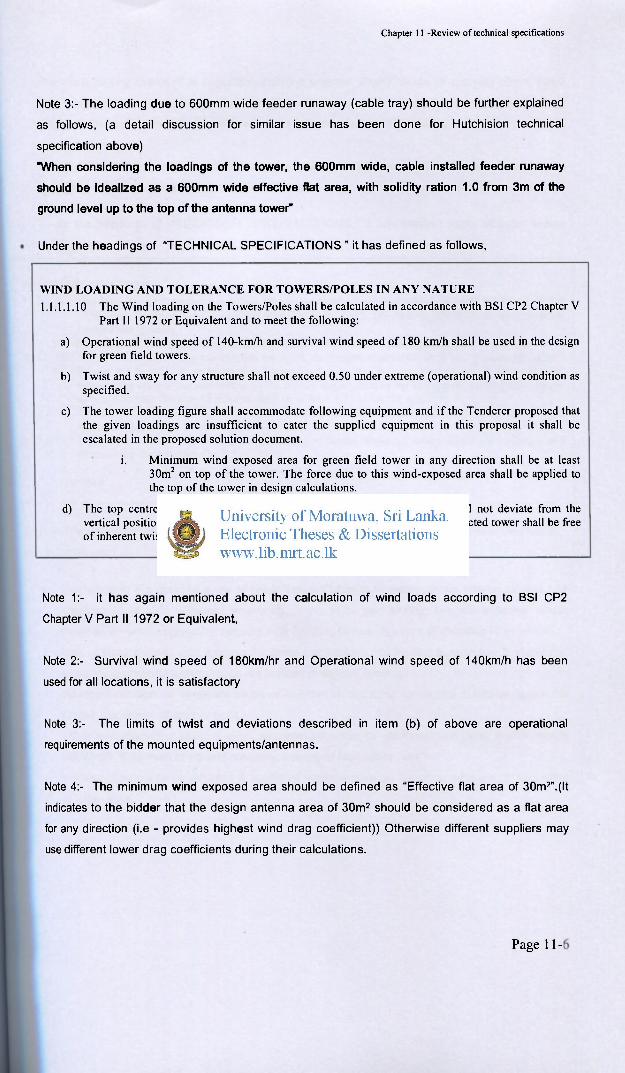
Note 3:- The loading due to 600mm wide feeder runaway (cable tray) should be further explained
as follows, (a detail discussion for similar issue has been done for Hutchision technical
specification above)
"When considering the loadings of the tower, the 600mm wide, cable installed feeder runaway
should be idealized as a 600mm wide effective flat area, with solidity ration 1.0 from 3m of the
ground level up to the top of the antenna tower"
Under the headings of "TECHNICAL SPECIFICATIONS " it has defined as follows,
WIND LOADING AND TOLERANCE FOR TOWERS/POLES IN ANY NATURE 1.1.1.1.10 The Wind loading on the Towers/Poles shall be calculated in accordance with BSI CP2 Chapter V
Part II 1972 or Equivalent and to meet the following:
a) Operational wind speed of 140-km/h and survival wind speed of 180 km/h shall be used in the design for green field towers.
b) Twist and sway for any structure shall not exceed 0.50 under extreme (operational) wind condition as specified.
c) The tower loading figure shall accommodate following equipment and if the Tenderer proposed that the given loadings are insufficient to cater the supplied equipment in this proposal it shall be escalated in the proposed solution document.
i. Minimum wind exposed area for green field tower in any direction shall be at least 30m2 on top of the tower. The force due to this wind-exposed area shall be applied to the top of the tower in design calculations.
d) The top centre of the erected tower/pole, under operational condition, shall not deviate from the vertical position by more than one eighth percent (1/8%) of its height. The erected tower shall be free of inherent twists.
Note 1:- it has again mentioned about the calculation of wind loads according to BSI CP2
Chapter V Part II 1972 or Equivalent,
Note 2:- Survival wind speed of 180km/hr and Operational wind speed of 140km/h has been
used for all locations, it is satisfactory
Note 3:- The limits of twist and deviations described in item (b) of above are operational
requirements of the mounted equipments/antennas.
Note 4:- The minimum wind exposed area should be defined as "Effective flat area of 30m2".(It
indicates to the bidder that the design antenna area of 30m2 should be considered as a flat area
for any direction (i.e - provides highest wind drag coefficient)) Otherwise different suppliers may
use different lower drag coefficients during their calculations.
Page 11-10
Chapter 11 -Review of technical specifications
The word "in any direction" is important, then the supplier should oblige to applying above same
total loads (due to 30m2 antennas at top of tower) for cross wind analysis ( wind applying along
diagonal direction of the tower) which will be usually the most critical loading pattern.
Note 5:- The details those described under item (d) is aesthetical requirements as similar to that
explained in Hutchision technical specification above.
• Under the headings of "TECHNICAL SPECIFICATIONS " it has defined some of basic design
criteria are as follows,
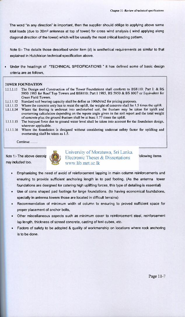
TOWER FOUNDATION 1.1.1.1.11 The Design and Construction of the Tower Foundations shall conform to BS8110: Part I: & BS
5950 1985 for Roof Top Towers and BS8110: Part I 1985, BS 5950 & BS 8007 or Equivalent for Green Field Towers.
1.1.1.1.12 Standard soil bearing capacity shall be define as 100kN/m2 for pricing purposes. 1.1.1.1.13 Where the concrete only has to resist the uplift, the weight of concrete shall be 1.5 times the uplift. 1.1.1.1.14 Where the footing is undercut into undisturbed soil, the frustum may be taken for uplift and
overturning calculation depending on the repose angle given in the soil report and the total weight of concrete plus the ground frustum shall be at least 1.77 times the uplift.
1.1.1.1.15 The buoyant force due to ground water level shall be taken into account for the foundation design, wherever applicable.
1.1.1.1.16 Where the foundation is designed without considering undercut safety factor for uplifting and overturning shall be taken as 1.5.
Continue
Note 1:- The above descriptions are well explained, in addition to above descriptions following items
may included too.
• Emphasizing the need of avoid of reinforcement lapping in main column reinforcements and
ensuring to provide sufficient anchoring length in to pad footing. (As the antenna tower
foundations are designed for catering high uplifting forces, this type of detailing is essential)
• Use of cone shaped pad footings for large foundations, (to having economical foundations,
specially in antenna towers those are located in difficult terrains)
• Recommendation of minimum width of column to ensuring to proved sufficient space for
proper placement of anchor bolts,
• Other miscellaneous aspects such as minimum cover to reinforcement steel, reinforcement
lap length, thickness of screed concrete, casting of test cubes, etc.
• Factors of safety to be adopted & quality of workmanship on locations where rock anchoring
is to be done.
Page 11-10
Chapter 11 -Review of technical specifications
11.3. Technical specification of Suntel - December 2 0 0 8 (Attachment A-3 )
• This document was attached in the tender document of supplying 50m, 60m, 70m and 80m
towers (All are Greenfield type towers) for Suntel Lanka (pvt) limited, Colombo in December 2008.
• This tender call bids for Supply, deliver and complete construction (erection) of towers in provided
locations.
• Under the headings of "General" it has described as follows,
1.0 GENARAL
The specification define the characteristics and performance requirement of the Tower to be purchased
1.1 For the performance specifications and characteristics witch are nor stated in this specification, the relevant standard and or recommendations as soecified in ELA RS -222C and BS449 shall apply:
1.2 Manufacturing and workmanship should comply to BS 449 or A R C
1.3 Minimum distance between legs at the top portion shall be type and 1 8m for 50m,60m.70m and 80mtowers.
1.4 The straight portion at the top shall be 10m for all towers above 50m m height.
Note 1> Although it has recommended use a design code of EIA RS-222C, there are another four
new versions (D, E, F & G) of same code also available. Most recently released version is
T1A/EIA222-G which includes many (new) important features. Therefore, it is better to request
tower designs according to most recent engineering code than old versions.
• Under the headings of "Design codes " it has described as follows,
2.0 DESIGN CODES
The American "'Structural standard fcr steel Antenna Towers and Antenna supporting Structures" RS222C or Tlie British codes of practices 3 chapter V part 2, 1972 shall be used
Note 1:- Both EIA222-C code and BSI CP2 Chapter V Part II 1972 are obsolete documents.
Therefore, we should use either ANSI/TIA222-G-2005 (Structural standard for Antenna supporting
structures and antennas-American) or BS8100-1986 (British standard for lattice towers and
masts)
Page 11-10
Chapter 11 -Review of technical specifications
• Under the headings of "Wind loading and tolerance " it has described as follows,
3.0 WEND LOADING AND TOLERANCE
3.1 Operational wmd speed of 120 k m h and survival wind speed of 160 km h should be used in the design
3.2 Twist and swing should not exceed 0.5 under extreme wmd condition as specified in 3.1.
3.3 The tower-loading :.(wind shield area of 32Sq.m in any one direction at top 3.4 A safer,- factor of 1.7 should be used. 3.5 The erected tower, under the condition of negligible wind, shall not deviate
from the vertical position by more than one eight percent (1/8%) of its heights, and shall straight within 2.5 cm of the normal Geometric position: the erected tower shall be free of inherent twists.
Note 1:- Survival wind speed of 160km/hr and Operational wind speed of 120-km/h has been
used for all locations, but it is not satisfactory for wind zone 2 and 3. On the other hand the new
policy for antenna structures of the TRC has been recommended to use 180km/hr wind speed for
all antenna structures that considering them as post disaster type structures.
Note 2:- The limits of twist and deviations described in item 3.2 of above are operational
requirements of the mounted equipments/antennas.
Note 3:- The tower loading conditions that has described in above item 3.3 should be done in
more detailed and precise manner. Otherwise the towers supplier may submit tenders with
providing their own different definitions for above design antenna area, etc.
Therefore, above description in item 3.3 should be corrected as follows,
The tower loading -: The minimum "Effective flat wind shielding area of 32m2".(i.e-lt indicates to
the bidder that the design antenna area of 32m2 should be considered as a flat area which
provides the highest wind drag coefficient) for any direction should be applied to the top level of
the structure.
Note 4:- The intension of using a general safety factor (in item 3.4) of 1.7 is not clear. Because
the overall factor of safety of structure (for wind loads) will be 1.78 ( i.e 1602/1202 = 1.78), the
factor of safety for material strength to be selected as value of 1.1 to 1.2 as appropriately. The
Factors of safety for foundation has been indicated separately in another section of above same
document, etc.
Note 5:- The item 3.5 of above, limit of deviation of erected structure, limit of twisting, etc. are
mostly important as the aesthetical aspects. Because, when the steel lattice structure is 100%
accurately constructed with supplying all of its members, such slight deviations or twists are not
much important factors for its structural stability.
Page 11-10
Chapter 11 -Review of technical specifications
Note 5:- Under the headings of Item 4.0 to 12.0, it described the details of quality of product and
workmanship required by the client.
However, it is important to add some further description about the design loading condition of
Feeder runaway as follows,
"When considering the loadings of the tower, the 600mm wide, cable installed feeder runaway
should be idealized as a 600mm wide effective flat area, with solidity ration 1.0 from 3m of the
ground level up to the top of the antenna tower"
Otherwise, tower suppliers may able to use different (i.e - lower) wind drag coefficients and
solidity ratios ( i.e - less than 1.0) for above idealizations. Such assumptions will make them to
achieve some benefits of lowering the final tower weight while reducing the design loading of the
tower.
Under the headings of "(13) Foundation" it mostly explaining about the quality of foundation &
workmanship that required by the client
Note:- In addition to the above quality aspects, it may necessary to be included some of primary
design criterions also in to this section. The primary design criterions those having large
influences on design of individual pad footings may be as follows,
• Standard soil bearing capacity to be assumed for pricing purposes (indicated above)
• Factor of safeties to be considered on design uplifting force for different situations such as,
good soil foundations with undercutting possible, when undercutting is not possible, water
logged foundations, etc.
• General factor of safety for overturning, sliding, etc. ( for example FOS=1.5)
• Type and quality of steel reinforcement to be used, (for example fy=460N/mm2, etc.)
• Grade of concrete, (for example Gr 25, etc.)
• Emphasizing the need of avoid of reinforcement lapping in main column reinforcements and
ensuring to provide sufficient anchoring length in to pad footing. (As the antenna tower
foundations are designed for catering high uplifting forces, this type of detailing is essential)
• Use of cone shaped pad footings for large foundations, (to having economical foundations,
specially in antenna towers those are located in difficult terrains)
• Recommendation of minimum width of column to ensuring to proved sufficient space for
proper placement of anchor bolts,
• Other miscellaneous aspects such as minimum cover to reinforcement steel, reinforcement
lap length, thickness of screed concrete, casting of test cubes, etc.
• Factor of safeties to be adopted & quality of workmanship on locations where rock anchoring
is to be done.
Page 11-10
Chapter 11 -Review of technical specifications
11.4. Technical specification of Lanka Bell - July 2008 (Attachment A-4)
• This document was attached in the tender document of supplying 50m, 60m, 70m, 80m &
100m towers (All are Greenfield type towers) for Lanka Bell (pvt) limited, Colombo.
• This tender call bids for Supply, deliver and complete construction (erection) of towers in
provided locations.
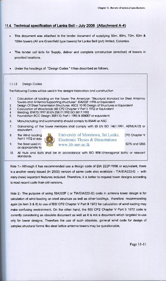
• Under the headings of "Design Codes " it has described as follows,
1.1.1.2 Design Codes
The Following Codes will be used in the designs fabrication and construction
1. Calculation of loading on the Tower: The American "Structural standard for Steel Antenna Towers and Antenna Supporting structures": EIA222F :1996 or Equivalent
2. Design Of Steel Transmission Structures: ASCE 10-90 Design of Structures or Equivalent 3. Calculation of Wind loads: BSI CP2 Chapter V Part II 1972 or Equivalent 4. Welding: EN970:1997 BS EN 25817:1992 ISO 5817:1992 5. Foundation RCC Design: BS8110: Part I: 1985 & BS8007 or equivalent
6. Manufacturing and workmanship should comply to BS449 or AISC
7. Galvanizing of the tower members shall comply with BS EN ISO 1461:1991, ASTM/A123 or equivalent.
8. The Wind loading on the Tower shall be calculated in accordance with BSI CP2 Chapter V Part II 1972 or equivalent
9. The Steel used in the fabrication of tower shall conform to BS EN 10025 Grade S275 and S355 as appropriate to Rolling Tolerance to relevant ISO standards.
10. All Nuts and Bolts shall be in accordance with ISO 898-1 (Hexagonal Bolts) or relevant standards.
Note 1:- Although it has recommended use a design code of EIA 222F:1996 or equivalent, there
is a another newly issued (in 2005) version of same code also available - TIA/EIA222-G - with
many (new) important features included. Therefore, it is better to request tower designs according
to most recent code than old versions.
Note 2:- The purpose of using EIA222F ( or TIA/EIA222-G) code in antenna tower design is for
calculation of wind loading on steel structure as well as other loadings, therefore recommending
again (in item 3 & 8) to use of BSI CP2 Chapter V Part II 1972 for calculation of wind loading may
make confusing environment. On the other hand, the BSI CP2 Chapter V Part II 1972 code is
currently considering as obsolete document as well as it is not a document which targeted to use
only for tower designs. Therefore the use of such obsolete, general wind code for design of
complex structural forms like steel lattice antenna towers may be questionable.
Page 11-10
Chapter 11 -Review of technical specifications
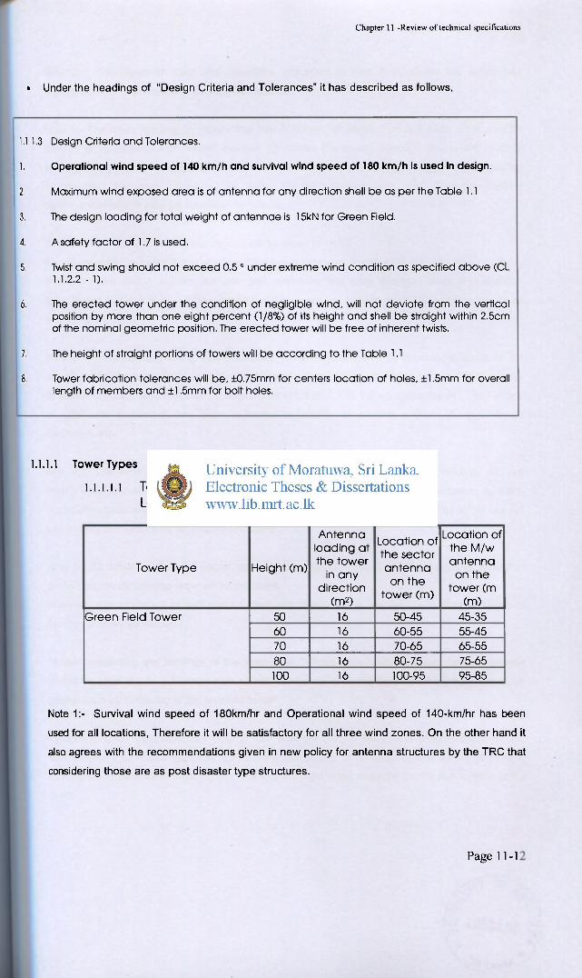
• Under the headings of "Design Criteria and Tolerances" it has described as follows,
1.1.1.3 Design Criteria and Tolerances.
1. Operational wind speed of 140 km/h and survival wind speed of 180 km/h is used in design.
2. Maximum wind exposed area is of antenna for any direction shell be as per the Table 1.1
3. The design loading for total weight of antennae is 15kN for Green Field.
4. A safety factor of 1.7 is used.
5. Twist and swing should not exceed 0.5 0 under extreme wind condition as specified above (CL 1 . 1 . 2 . 2 - 1 ) .
6. The erected tower under the condition of negligible wind, will not deviate from the vertical position by more than one eight percent (1/8%) of its height and shell be straight within 2.5cm of the nominal geometric position. The erected tower will be free of inherent twists.
7. The height of straight portions of towers will be according to the Table 1.1
8. Tower fabrication tolerances will be, ±0.75mm for centers location of holes, ±1,5mm for overall length of members and ±1,5mm for bolt holes.
1.1.1.1 Tower Types
l.i.i.i.i Table 1.1 - Tower Height and Loading Details
Tower Type Height (m)
An tenna loading at the tower
in any direct ion
(m2)
Locat ion of the sector an tenna
on the tower (m)
Location of the M /w antenna
on the tower (m
(m) Green Field Tower 50 16 50-45 45-35 Green Field Tower
60 16 60-55 55-45 Green Field Tower
70 16 70-65 65-55
Green Field Tower
80 16 80-75 75-65
Green Field Tower
100 16 100-95 95-85
Note 1:- Survival wind speed of 180km/hr and Operational wind speed of 140-km/hr has been
used for all locations, Therefore it will be satisfactory for all three wind zones. On the other hand it
also agrees with the recommendations given in new policy for antenna structures by the TRC that
considering those are as post disaster type structures.
P a g e 11-10
Chapter 11 -Review of technical specifications
Note 2:- The limits of twist and deviations described in item 5 of above are operational
requirements of the mounted equipments/antennas.
Note 3:- The tower loading conditions that has described in above item 2 & table 1.1 should be
done in more detailed and precise manner. Otherwise the towers supplier may submit tenders
with providing their own different definitions (which may not providing the worse design loading
arrangement for tower structure) for above design antenna area, etc. Therefore, above
description in item 2 may be corrected as follows,
Total wind shielding area of the antennas will be equal to 16m2
Above antennas includes 6 nos of 0.5mx2.5m panel antennas arranged at top (attachment A-04a)
and 2 x 1.8m and 1 x 2.0m diameter dish antennas that may arranged in to any direction
(attachment A-04b & A-04c). The mounting arrangement and heights of all above antennas will be
according the table 1.1
Note 4:- The purpose of using a general safety factor (in item 4) of 1.70 is not clear. Because the
overall factor of safety of structure (for wind loads) will be 1.65 ( i .e 1802/1402 = 1.65), the factor
of safety for material strength to be selected as value of 1.1 to 1.2 as appropriately. The Factors
of safety for foundation has been indicated separately in another section of above same
document, etc.
Note 5> The item 6 of above, limit of deviation of erected structure, limit of twisting, etc. are
mostly important as the aesthetical aspects. Because, when the steel lattice structure is 100%
accurately constructed with supplying all of its members, such slight deviations or twists are not
much important factors for its structural stability.
Note 5:- All other sections of above technical specification described the details of quality of
product and workmanship required by the client.
However, it is important to add some further description about the design loading condition of
Feeder runaway as follows,
"When considering the loadings of the tower, the 500mm wide, cable installed feeder runaway
should be idealized as a 500mm wide effective flat area, with solidity ratio of 1.0 from 3m of the
ground level up to the top of the antenna tower"
Otherwise, tower suppliers may able to use different (i.e - lower) wind drag coefficients and
solidity ratios ( i.e - less than 1.0) for above idealizations. Such assumptions will make them to
achieve some benefits of lowering the final tower weight while reducing the design loading of the
tower.
Page 11-13
Chapter 11 -Review of technical specifications
Under the headings of "1.1.2 Technical Specifications for Tower Foundations" it mostly
explaining about the quality of foundation & workmanship that required by the client
Note:- In addition to the above quality aspects, it may necessary to be included some of primary
design criterions also in to this section. The primary design criterions those having large
influences on design of individual pad footings may be as follows,
• Standard soil bearing capacity to be assumed for pricing purposes (indicated above)
• Factor of safeties to be considered on design uplifting force for different situations such as,
good soil foundations with undercutting possible, when undercutting is not possible, water
logged foundations, etc.
• General factor of safety for overturning, sliding, etc. (for example FOS=1.5)
• Type and quality of steel reinforcement to be used, (for example fy=460N/mm2, etc.)
• Grade of concrete, (for example Gr 25, etc.)
• Emphasizing the need of avoid of reinforcement lapping in main column reinforcements and
ensuring to provide sufficient anchoring length in to pad footing. (As the antenna tower
foundations are designed for catering high uplifting forces, this type of detailing is essential)
• Use of cone shaped pad footings for large foundations, (to having economical foundations,
specially in antenna towers those are located in difficult terrains)
• Recommendation of minimum width of column to ensuring to proved sufficient space for
proper placement of anchor bolts,
• Other miscellaneous aspects such as minimum cover to reinforcement steel, reinforcement
lap length, thickness of screed concrete, casting of test cubes, etc.
• Factors of safety to be adopted & quality of workmanship on locations where rock anchoring
is to be done.
Page 11-10
Chapter 11 -Review of technical specifications
11.5. Technical specification of Safar icom ( K e n y a ) - J a n u a r y 2 0 1 0 (At tachment A-5 )
• This document was attached in the tender document of supplying 50m, 60m, 80m Greenfield
towers & 21m rooftop towers for Safaricom limited, Kenya.
• This tender call bids for Supply, deliver and complete construction (erection) of towers in provided
locations.
• As a general details, it has described as follows,
1.1,1. L o a d i n g
Objective:
The objective of this sect ion is to provide m i n i m u m des ign criteria fo r self supporting steel lattice towers and monopoles
Service life
The expected service l i fe of towers and monopoles shall be 25 j-ears The design, choice c : fabrication materials, fabricat ion methods, installation accessories, all safety factors and tower moaopole loadings shall all be made to conform to standards for this to b e achieved.
Note 1:- It explains the objective of the loading criterion given in above technical specification as
the minimum required design criteria for self standing towers and monopoles. Therefore, the
tendorers can provide suitable families of towers to suit above minimum criteria.
• Under the headings of "Design loads " it has described as follows, For t i e basic wind speeds ai Kenya, die following table shall be used as a guide
Location Description Basic W i n d Speed, m s
1 Nairobi. Central Province & southern half of Eastern Province including Machakos. Tliika & Nyeii
2S Region 1
1 Coast Province including Vo:. Malindi & Mombasa 31 3 Southern half of Rift Valley Province including Nakuru.
Naivasha. Narok. Rumuruti. Nanyuki & Magads 36 Region 2
4 North Eastern Province, Northern half of Eastern & Rift Valley Provinces including Eldoret. Kitale & Kericho
45 Region 3
5 Nyanza & Western Provinces including Kisumu. Kakamega. Busia & Kisii
46
The basic wind speed shall be read 6 c m this table whereas the design wind speed shall be obtained from methods given in BS C?3 Chapter V: Part 2.
Note 1:- The basic wind speed for different region of Kenya has given as a guideline. It will help to
decide design wind speed for given regions.
P a g e 11-10
Chapter 11 -Review of technical specifications
• Under the headings of "Loading " it has described as follows,
There will be two types of towers fbi every region: namely normal dun- and heavy dot*'.
The towers shall be designed to cater foi the following antenna equipment
NORMAL DUTY: 6 Nos. 2.6m long GSM and 1.2 m 0 M W « top. and 2 nos. 1.2m 0 M/W just below.
HEAVY DUTY: 6 nos. GSM a top. and 4 nos 1 S r u 0 M W 5m below, and 4 ncs 1.8m 0 MW 10m further below.
NOTE; Heavy Duty towers shall always be four ".egged.
Note 1:- The proposed arrangements of antennas were given. This may be the best way of
obtaining most economized structures for large quantity of tower requirements.
Note 2:- If the samples of GSM and MW antennas were given, the details will be more completed.
Otherwise the drag coefficients of above two types of antennas to be given.
Note 3:- The design loading due to cable tray has not included above or any other sections of the
technical specification.
The deflection of the structure shall not exceed the maximum allowable sway of =0.50 degrees at the centre of the top most MW position, at S0 :» of the basic wind speed as stated in table above.
Note 3:- The operational requirements were given above in slightly different wordings,
Minimum Dead and Lh t' Load
Ike dead loads to be considered in design shall include self weight of towei monopole. GSM and M/W antenna, feeder cables, mounting brackets, fixtures and fittings and access ladder and platforms. A s allowance of about 5°o of the structure weight shall be ma de for galvanising and fasteners.
| The bye loads to be considered shall include workers climbing for installation inspection
• Under the headings of "Tower designs " it has described as follows,
All steel structures shall be designed in accordance with BS5950. Tower designs shall also conform to BS 8100
The tower shall be designed to resist the most onerous combination of loading resulting from wind acting on towers, ancillaries. antennae and feeders.
Note 1:- The above two sentences clearly described the code of practice and load combination to
be adopted.
Page 11-10
Chapter 11 -Review of technical specifications
At die time of submission of a new tower monopole type nevei deployed in Safaricom Limited network before for Safaricom Limited's approval with SoC. die contractor shall submit a bound structural analysis & design report, including the tower sauctural drawings and mode.', in soft copy either in STAAD pro, Prokon 02 STRAP programmes, for each new tower to be supplied. Tower structural drawings shall indicate region, material strengths, dimensions, member sizes, platform positions, ladder, design load and any ether relevant notes. These calculations must clearly indicate both the net (as obtained from structural analysis) and gross weight of tower.
If vendor bids for a tower that has been deployed in the Safaricom Limited network before, reference to approved documents should be made and drawings of tower submitted with these SoCs. These structural drawings shall indicate region, material strengths, dimensions, member sizes, platform positions, ladder, design Load and any other relevant notes.
All structural design (drawings and calculations) submitted to Safaricom Limited, must be clearly marked to show they have been approved for use in Kenya by a Structural Engineer registered by Kenya's Engineers Registration Board or IEK.
Note 2:- The client is asking all the details and computer model of each towers for their own
evaluations.
Note 3:- In one aspect, it can argue as the wise choice of requesting tender bidders to submit
computer models of above proposed towers in software (i.e STAAD Pro, Prokon or STRAP)
which are available with client in his facility. But the use of more specific software those are
using only for designing of steel lattice antenna towers will be always advantage - as discussed in
earlier sections of this report.
Note 4:- It has clearly requested that the each drawings should have to be well detailed with all
basic details.
Note 5:- All structural drawing are requested to be validated by a structural engineer registered in
Kenya's Engineering Registration Board or IEK. ( In Sri Lanka, this type of validation of design
calculations by local experts is not always requested.)
• Under the headings of "Modular requirement" it has described as follows,
1.1.2. Modu lar Requirement
The tower shall be of lattice bolted construction, square or triangular in sec metric cross section. The tower shall be made up of 5m or 6m modular sections enabling complete flexibility over the height requirements
Note 2:- This is very useful for operation and maintenance aspects of the structures.
Page 11-10
Chapter 11 -Review of technical specifications
• Under the headings of "Foundation designs " it has described as follows,
1.1.3. F o o t p r i n t R e q u i r e m e n t and F o u n d a t i o n Design
Tie footprint sk i l l b« the smallest possible meeting the loading requirements specified in this document.
Tie foundation designs and drawings shall also be submitted with these SoCs 7c r ea; l i tower to be supplied, the vendor shall provide the fo l lowing options fc r tower foundations sanely ground raft for soil bearing capacity of 200 kpa. underground raft and separate pads for soil bearing capacity 120 to 150 kpa and underground raft tor soil bearing capacity of SC to 100 kpa.
All structural designs for foundat ions (drawings and calculations) must be submitted to Sararitom Limited with the SoC and be clearly marked to show they have been approved for use in Kenya by a Structural Engineer registered by Kenya ' s Engineers Registration Board orIEK
• Note 1:- In addition to the above described basic requirements, it may necessary to be included
some other primary design criterions too. The primary design criterions those having large
influences on design of individual pad footings may be as follows,
• Standard soil bearing capacity to be assumed for pricing purposes (indicated above)
• Factor of safeties to be considered on design uplifting force for different situations such as,
good soil foundations with undercutting possible, when undercutting is not possible, water
logged foundations, etc.
• General factor of safety for overturning, sliding, etc. ( for example FOS=1.5)
• Type and quality of steel reinforcement to be used, (for example fy=460N/mm2, etc.)
• Grade of concrete, (for example Gr 25, etc.)
• Emphasizing the need of avoid of reinforcement lapping in main column reinforcements and
ensuring to provide sufficient anchoring length in to pad footing. (As the antenna tower
foundations are designed for catering high uplifting forces, this type of detailing is essential)
• Use of cone shaped pad footings for large foundations, (to having economical foundations,
specially in antenna towers those are located in difficult terrains)
• Recommendation of minimum width of column to ensuring to proved sufficient space for
proper placement of anchor bolts,
• Other miscellaneous aspects such as minimum cover to reinforcement steel, reinforcement
lap length, thickness of screed concrete, casting of test cubes, etc.
• Factors of safety to be adopted & quality of workmanship on locations where rock anchoring
is to be done.
Page 11-10
Chapter 11 -Review of technical specifications
• Under the headings of "Tower member requirement" it has described as follows,
1.1.4. Tower Member Requirement
Lez members. main and. secondary bracmss shall be manufactured from hot rolled steel sections, either ui angle 01 tubular hollow sections For the coastal region. angular section: shall be preferred to tubular hollow sections.
Note 1:- It has clearly requested not to use tubular hollow sections for coastal regions. Generally the
tubular hollow members are having higher tendency for heavy corrosion due to the reasons such as
they are having comparatively thinner members, usually inside of members are not well galvanized,
more welded joints, etc.
• Under the headings of "Structural steelwork " it has described as follows,
1.1.?. St ructura l Steelwork
All structural steelwork shall be in accordance with BS4360 Grades 50C. 40B & SOB
Hot roiled angled sections shall conform to BS4S4S: Part 4 1972
Hot rolled structural hollow sections shall be to BS434S: Part 2: 1972.
All bolts shall be in accordance with BS4190 and each supplied complete with single nut. single coil spring washer and flat washer
Fabrication shall be generally carried out in accordance with the requirements of BS5950
All welding shall be performed before the galvanizing process and shall conform to BS5135.
All steelwork shall conform to structural loading requirement;, structural steel specifications and local market availability.
Note 1:- Basic requirements are described above sufficiently
Page 11-10
Chapter 11 -Review of technical specifications
11.6. Technical specification of Orange (France/Africa) -December 2008(Attachment A-6)
This document was attached in the tender document of Design, Manufacture, Delivery of Towers and
Masts (Both Greenfield and Rooftop type structures) for Orange Telecommunication limited, Kenya.
• Under the headings of "Design " it has described as follows,
Design Two (2) standard / code are allowed:
EIA/TIA-222-G with addendum G1 NV 65 -DTU P06-002 version of 2000
Per consequence the following calculation rules for steel constructions shall be used AISC- LRFD 99 - Load and Resistance Factor Design Specification for Structural Steel Building P 22.701 CM 66 Rules and addition 80: Metal construction rules - Calculation rules for steel constructions edited in 1966
These Standards / Codes shall be imperatively used to design standard tower. Using equivalent or others Standard/Code for standard tower is not allowed.
The tower should be designed in such a manor that the connections are not the critical or weakest link.
Note 1> Only two design codes are allowed.
Note 2> The towers were requested to be designed in such a way that the connections are not
the critical or weakest link.
• Under the headings of "Design notes " it has described as follows,
Design note The structure's design note is to be supplied to Purchaser for each tower or mast delivered. The design note will include a hypothesis note defining the base values of the wind and the various coefficients taken into account (site, dimension, height, dynamic and drag, etc.) and the surfaces considered and the type of links at the bearings and between the bars. The name, the origin and the characteristics of the software used shall be specified.
The stability and the solidity of the structure will be checked according the allowed standard / code
E.g :With the wind pressures corresponding to the extreme wind of NV65.
The dimensions of the pylon's and mast's anchorage and the checking of mast fatigue may be carried out as per the Recommendations on the calculation of the mast structure for the lighting of open spaces
published in CTICM's Metal Construction report, no. 4 of 2000. AISC - LRFD 99
Page 11-10
Chapter 11 -Review of technical specifications
Note 1:- It requested to include all the technical details in each report of tower as seperate notes.
This will make sure that all necessary design details will included in to design report and
submitted to the client. Therefore, No hidden factors, etc. are allowed to be used by the supplier
for his designs.
• Under the headings of " Wind " it has described as follows,
Wind The impacts of the wind will be considered on the pylon's structure, the ladder, the platforms, the cable paths, the antenna and their accessories. The tower and mast will be adapted to the wind zone encountered.
EIA/TIA-222-G1 ( 3 Sec Gust wind speed at
10 m height)
NV 65 ( 1 0 Min Ave wind speed at
10 m height)
Wind Area A Basic wind speed : 149,7 Km/h Normal speed: 103,0 Km/h Extrem speed: 136,1 Km/h
Wind Area B Basic wind speed :162,5 Km/h Normal speed: 112,7 Km/h Extrem speed: 149,1 Km/h
Wind Area C Basic wind speed :181,8 Km/h Normal speed: 126,0 Km/h Extrem speed: 166,6 Km/h
Wind Area D Basic wind speed : 197,9 Km/h Normal speed: 137,9 Km/h Extrem speed: 182,5 Km/h
Wind Area E Basic wind speed :228,5 Km/h Normal speed: 159,2 Km/h Extrem speed: 210,6 Km/h
Wind Area F Basic wind speed :251,0 Km/h Normal speed: 174,4 Km/h Extrem speed: 230,7 Km/h
For exposed site, the superior class should be taken E.g: Wind Area B is corresponding to Wind Area A for exposed site
(For TIA-222-G the Exposure Categories as per 2.6.5 are to be followed) The Tower height will be limited for the wind area D, E, F Note: the wind speed are given for 10m height
Note 1:- Design Wind speeds for different categories were clearly given.
• Under the headings of "Antenna Effective projected area " it has described as follows,
Antennas Effective Projected Area (EPA) Antenna Effective Projected Area (EPA) includes only the load for the antennas ( GSM and MW). Feeder, cable tray, platform, (etc..) impacts are not included in the EPA value. The tenderer shall consider the following typical values for the antennas Effective Projected Area (EPA) for the tower (greenfield site).
The typical values are: 6 sqm and 300 Kg, 12 sqm and 600 Kg, 20 sqm and 1100 Kg, 25 sqm and 1300 Kg The location is : 1.1 In the last 3 meters for the 6sqm
In the last 5 meters for the 12 sqm In the last 10 meters for the 20 and 25 sqm
Page 11-10
Chapter 11 -Review of technical specifications
The tenderer shall consider the following typical values for the antennas Effective Projected Area (EPA) for the tower (rooftop site).
The typical values are: 6 sqm and 300 Kg, 12 sqm and 600 Kg The location is :
In the last 3 meters for the 6sqm In the last 5 meters for the 12 sqm
The tenderer shall consider the following typical values for the antennas Effective Projected Area (EPA) for the pole (rooftop site).
The typical values are: 2 sqm and 100 Kg The location is :
In the last 2 meters
Note 1:- The design antenna area and their location of loading have been clearly indicated. All
antenna areas are supplied as Effective projected areas (EFA).
• Under the headings of "Transmission lines " it has described as follows,
Transmission lines (Feeder) The manufacturer will consider a width for a wind projected area of at least 50cm for the tower and a weight of 16 Kg / meter for feeders, with the except of the towers up to 36m with a EPA of 6sqm, in this case 350mm can be used for the feeder projected area.
In specific case (on purchaser request), a second cable ladder could be added. The position should be studied to limit the wind load.
For the pole, the manufacturer will consider a width for a wind projected area of at least 25 cm for the pole.
Note 1:- The design area of feeder line have been clearly indicated as Effective projected areas
(EFA).
Page 11-10
Chapter 11 -Review of technical specifications
• Under the headings of "Tilt, Twist and Sway" it described as follows
1.1.2 Tilt, Twist and sway The maximum authorised tilt, twist and sway for the tower and mast will be of: (See #13 for loading tables) ± 1°at the top for pole 2sqm load
± 1 "at the top for tower 6sqm load ± 1°at2,5 m of the top for tower-12sqm load (Cast 1) ± 30' at 2,5 m of the top for tower 12sqm load (Case 2) ± 20' at 5 m of the top for tower 20 and 25 sqm load
Note 3:- The necessary details are clearly defined above
• Under the headings of "Foundation " it described as follows
1.1.3 Foundation The tower shall be compatible with the different soil quality (defined in chapter 7.1.1 of "Civil works and Tower installation -annex"
To summarize, the typical soil quality are: - 200 kPa -150kPa -100 kPa - 50 kPa
These values are given in ELU ( Ultimate limit)
Note 3:- The necessary details are clearly defined above and in separate chapter.
• Under the headings of "Other parameters " it described as follows
1.1.4 Other parameters For design with EIA/TIA -222G with addendum, the following parameters shall be considered:
Exposure category: C Topographic category: 1 Classification of structure: 2
For design with NV65, the following parameters shall be considered: Site effect: normal No cliff effect
Note 3:- All other parameters relevant to two design codes were clearly defined above.
Page 11-10
Chapter 11 -Review of technical specifications
• Under the headings of "Report" it described as follows
1.2 Report
The report shall include: The parameters defined for the design calculation The impact of the accessories (ladder, work platform, feeder, ..)
r Steel quality Ratio of the admissible resistance for the element of tower part (critical part)
> Anchorage of the tower ( number, repartition and diameter) f Reference of the tool for design
Note 3:- All details required that included in report were clearly defined above.
• Under the headings of "Type of equipment to be installed for tower" it has described details of
Cable ladder and Access ladder as a mandatory requirements.
Note 3:- All bidders were forced to supply above important service requirements according to the
given details.
• Under the several different headings all other details ( width at the top, quality of materials,
workmanship, labeling, documentation, etc) were described accordingly.
Note 3:- All precautions were taken for the quality of product to be keeping in one category. All
required details were provided to the bidders and therefore, no allocations for supply the products
with different qualities.
Note: - When comparing with all other technical specifications which are reviewed
here, the technical specification issued by Orange can be considered as well