+ All Categories
Home > Documents > 11/01 ECLIPSE FLUEFIRE BURNERS - techritecontrols.com.au

11/01 ECLIPSE FLUEFIRE BURNERS - techritecontrols.com.au

Date post: 19-Nov-2021
Category:
Upload: others
View: 2 times
Download: 0 times
Share this document with a friend
2
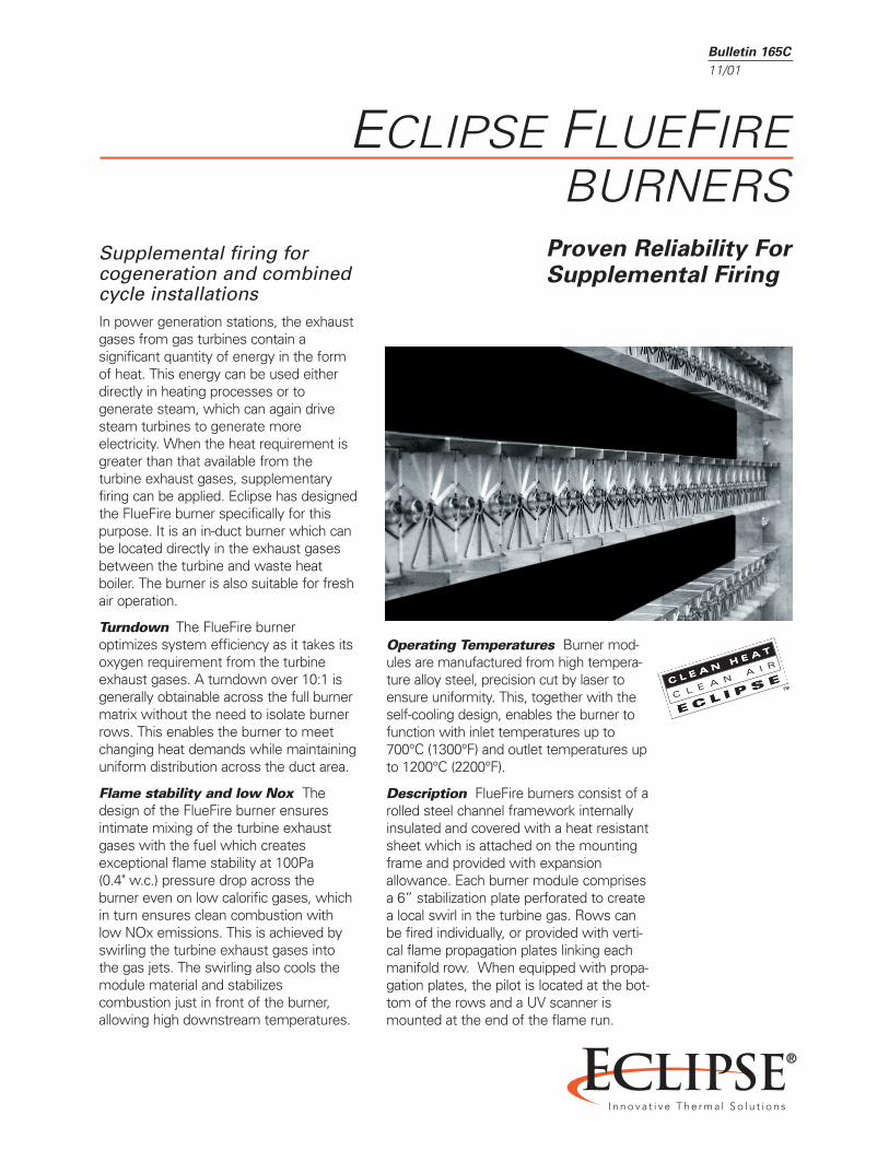
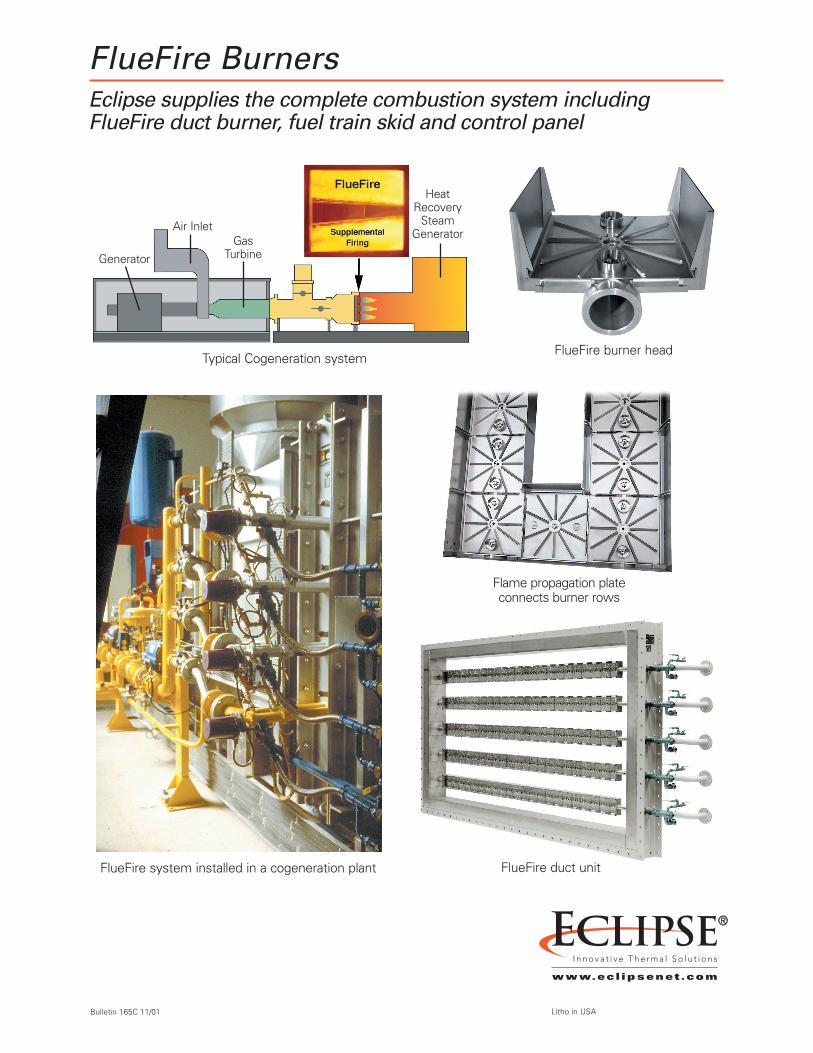
Bulletin 165C 11/01 Proven Reliability For Supplemental Firing ECLIPSE FLUEFIRE BURNERS E C L I P S E Supplemental firing for cogeneration and combined cycle installations In power generation stations, the exhaust gases from gas turbines contain a significant quantity of energy in the form of heat. This energy can be used either directly in heating processes or to generate steam, which can again drive steam turbines to generate more electricity. When the heat requirement is greater than that available from the turbine exhaust gases, supplementary firing can be applied. Eclipse has designed the FlueFire burner specifically for this purpose. It is an in-duct burner which can be located directly in the exhaust gases between the turbine and waste heat boiler. The burner is also suitable for fresh air operation. Turndown The FlueFire burner optimizes system efficiency as it takes its oxygen requirement from the turbine exhaust gases. A turndown over 10:1 is generally obtainable across the full burner matrix without the need to isolate burner rows. This enables the burner to meet changing heat demands while maintaining uniform distribution across the duct area. Flame stability and low Nox The design of the FlueFire burner ensures intimate mixing of the turbine exhaust gases with the fuel which creates exceptional flame stability at 100Pa (0.4" w.c.) pressure drop across the burner even on low calorific gases, which in turn ensures clean combustion with low NOx emissions. This is achieved by swirling the turbine exhaust gases into the gas jets. The swirling also cools the module material and stabilizes combustion just in front of the burner, allowing high downstream temperatures. Operating Temperatures Burner mod- ules are manufactured from high tempera- ture alloy steel, precision cut by laser to ensure uniformity. This, together with the self-cooling design, enables the burner to function with inlet temperatures up to 700°C (1300°F) and outlet temperatures up to 1200°C (2200°F). Description FlueFire burners consist of a rolled steel channel framework internally insulated and covered with a heat resistant sheet which is attached on the mounting frame and provided with expansion allowance. Each burner module comprises a 6” stabilization plate perforated to create a local swirl in the turbine gas. Rows can be fired individually, or provided with verti- cal flame propagation plates linking each manifold row. When equipped with propa- gation plates, the pilot is located at the bot- tom of the rows and a UV scanner is mounted at the end of the flame run.
Transcript

Bulletin 165C

11/01

Proven Reliability ForSupplemental Firing

ECLIPSE FLUEFIREBURNERS

E C L I P S E

Supplemental firing forcogeneration and combinedcycle installationsIn power generation stations, the exhaustgases from gas turbines contain a significant quantity of energy in the formof heat. This energy can be used eitherdirectly in heating processes or to generate steam, which can again drivesteam turbines to generate more electricity. When the heat requirement isgreater than that available from the turbine exhaust gases, supplementary firing can be applied. Eclipse has designedthe FlueFire burner specifically for thispurpose. It is an in-duct burner which canbe located directly in the exhaust gasesbetween the turbine and waste heat boiler. The burner is also suitable for freshair operation.

Turndown The FlueFire burner optimizes system efficiency as it takes itsoxygen requirement from the turbineexhaust gases. A turndown over 10:1 isgenerally obtainable across the full burnermatrix without the need to isolate burnerrows. This enables the burner to meetchanging heat demands while maintaininguniform distribution across the duct area.

Flame stability and low Nox Thedesign of the FlueFire burner ensures intimate mixing of the turbine exhaustgases with the fuel which creates exceptional flame stability at 100Pa(0.4" w.c.) pressure drop across the burner even on low calorific gases, whichin turn ensures clean combustion withlow NOx emissions. This is achieved byswirling the turbine exhaust gases intothe gas jets. The swirling also cools themodule material and stabilizes combustion just in front of the burner,allowing high downstream temperatures.

Operating Temperatures Burner mod-ules are manufactured from high tempera-ture alloy steel, precision cut by laser toensure uniformity. This, together with theself-cooling design, enables the burner tofunction with inlet temperatures up to700°C (1300°F) and outlet temperatures upto 1200°C (2200°F).

Description FlueFire burners consist of arolled steel channel framework internallyinsulated and covered with a heat resistantsheet which is attached on the mountingframe and provided with expansionallowance. Each burner module comprisesa 6” stabilization plate perforated to createa local swirl in the turbine gas. Rows canbe fired individually, or provided with verti-cal flame propagation plates linking eachmanifold row. When equipped with propa-gation plates, the pilot is located at the bot-tom of the rows and a UV scanner ismounted at the end of the flame run.

FlueFire BurnersEclipse supplies the complete combustion system including FlueFire duct burner, fuel train skid and control panel

Bulletin 165C 11/01 Litho in USA

FlueFire burner headTypical Cogeneration system

FlueFire duct unit

Flame propagation plateconnects burner rows

FlueFire system installed in a cogeneration plant

Generator

Air InletGas

Turbine

HeatRecovery

Steam Generator


Recommended