+ All Categories
Home > Documents > 111. High Efficiency Digital Co

111. High Efficiency Digital Co

Date post: 28-Feb-2018
Category:
Upload: imran
View: 215 times
Download: 0 times
Share this document with a friend
9
IEEE TRANSACTIONS ON INDUSTRIAL ELECTRONICS, VOL. 60, NO. 2, FEBRUARY 2013 773 High-Efci ency Digital-Controlled Interleav ed Power Converter for High-Power PEM Fuel-Cell Applications Shih-Jen Cheng, Yu-Kang Lo,  Member, IEEE , Huang-Jen Chiu,  Senior Member, IEEE , and Shu-Wei Kuo  Abstract—A high-efcienc y digital-co ntrolled interlea ved dc–dc con ver ter is desig ned and imple ment ed to pro vide a reg ulat ed high voltage output for high-power proton-exchange-membrane fuel- cell appli cati ons. Rippl e canc ella tion on input curr ent and output voltage can be achieved by the studied interleaved dc–dc powe r con ver sion tech nique to red uce hyst ere sis ener gy loss es insid e the fuel -cel l stac ks and meet battery charg ing cons ider - ations on the high-voltage dc bus. An active-clamped circuit is also used to reduce the voltage spike on the power switches for rais ing the syst em rel iabil ity . The oper atio n princ iples and the design considerations of the studied power converter are analyzed and discussed in detail. Finally, a 10-kW laboratory prototype is built and tested. The experimental results are shown to verify the feasibility of the proposed scheme.  Index T erms—Active-clamped circuit, digital control, fuel cell, interleav ed dc–dc converter, ripple cancellatio n. I. I NTRODUCTION P ROTON exchange membrane (PEM) fuel cell is a device that converts chemical fuels into electric power, with many advantages such as clean electricity generation, high-current- output ability, high energy density, and high efciency. The PEM fuel cell pr esen ts a lo w volta ge ou tput with a wide ran ge of va ria tio ns [1] –[3 ]. As shown in Fig . 1, a ste p-u p dc–dc converter is always necessary for providing a regulated high-voltage output to the poststage dc–ac inverter in high- powe r grid-t ied applicatio ns. For the PEM fuel-cell system applications, the dc–dc converter must be concerned with the following design criteria: large step-up ratio, low-input-current ripple, and isolation [4]–[6]. Typically, an input choke with high inductance is needed at the low-voltage side because high ripple current may cause undesir ed hyste resis energy losses inside the fuel-cell stacks [7]–[10]. Increased power loss and compon ent siz e on the input choke are sig nican t to res ult in poor conversion efciency and low power density for the step-up dc–dc converters in high-power PEM fuel-cell systems. Manuscript received June 9, 2012; accepted June 14, 2012. Date of publi- cation July 6, 2012; date of current version September 13, 2012. This work was supported by the National Science Council of Taiwan under Grant NSC 100-2628-E-011-009-MY3. The aut hor s are wit h the Dep art men t of Ele ctr onic Eng ine eri ng, Na- tional Taiwan University of Science and Technology, Taipei 10607, Taiwan (e-mail: D9602201@mail.ntust.edu.tw; [email protected]; yklo@mail. ntust.edu.tw; M9802215 @mail.ntust.eud.t w). Color versions of one or more of the gures in this paper are available online at http://ieeexplore.ieee.org. Digital Object Identier 10.1109/TIE.2012.2206349 Fig. 1. PEM fuel-cell power converter system. Fig. 2. Digital con trolled in terleaved dc–dc c onverter . In this paper, a digital-controlled interleaved dc–dc converter shown in Fig. 2 is designed and implemented to achieve low- input-current ripple and high-efciency power conversion by the developed ripple cancellation characteristics at the high- current side and voltage-doubler topology at the high-voltage side. Bec aus e the fue l-c ell stack lac ks sto rag e abi lit y for ele ctr ic energy, an energy-storage device such as the Li-ion battery is usually used on the high-voltage output dc bus of the power con vert er in pract ical high-p ower appli catio ns [11]–[ 13]. A const ant-v oltag e (CV) feedb ack contr ol with a curren t-limit (CL) protect ion design is reali zed to raise the reliabilit y of the studied fuel-cell power converter. Combined with the studied int erl ea ve d ope rat ion, out put sides of the cur rent-fed dc–dc con - verters are connected in parallel to present a low-output-voltage ripple that is preferred for the battery charging considerations [14], [15]. Moreover, there is no voltage-imbalance problem that exists among the output capacitors of dc–dc converters connected in series. An active-clamped circuit for the current- fed dc–dc converter is also used to suppress the voltage spike on power switches that is usually a critical issue in practical high-power applications [16]–[19]. 0278-0046 /$31.00 © 2012 IEEE
Transcript

7/25/2019 111. High Efficiency Digital Co

http://slidepdf.com/reader/full/111-high-efficiency-digital-co 1/8

IEEE TRANSACTIONS ON INDUSTRIAL ELECTRONICS, VOL. 60, NO. 2, FEBRUARY 2013 773

High-Efficiency Digital-Controlled InterleavedPower Converter for High-Power

PEM Fuel-Cell ApplicationsShih-Jen Cheng, Yu-Kang Lo, Member, IEEE , Huang-Jen Chiu, Senior Member, IEEE , and Shu-Wei Kuo

 Abstract—A high-efficiency digital-controlled interleaved dc–dcconverter is designed and implemented to provide a regulatedhigh voltage output for high-power proton-exchange-membranefuel-cell applications. Ripple cancellation on input current andoutput voltage can be achieved by the studied interleaved dc–dcpower conversion technique to reduce hysteresis energy lossesinside the fuel-cell stacks and meet battery charging consider-ations on the high-voltage dc bus. An active-clamped circuit is

also used to reduce the voltage spike on the power switches forraising the system reliability. The operation principles and thedesign considerations of the studied power converter are analyzedand discussed in detail. Finally, a 10-kW laboratory prototype isbuilt and tested. The experimental results are shown to verify thefeasibility of the proposed scheme.

 Index Terms—Active-clamped circuit, digital control, fuel cell,interleaved dc–dc converter, ripple cancellation.

I. INTRODUCTION

PROTON exchange membrane (PEM) fuel cell is a device

that converts chemical fuels into electric power, with many

advantages such as clean electricity generation, high-current-

output ability, high energy density, and high efficiency. ThePEM fuel cell presents a low voltage output with a wide

range of variations [1]–[3]. As shown in Fig. 1, a step-up

dc–dc converter is always necessary for providing a regulated

high-voltage output to the poststage dc–ac inverter in high-

power grid-tied applications. For the PEM fuel-cell system

applications, the dc–dc converter must be concerned with the

following design criteria: large step-up ratio, low-input-current

ripple, and isolation [4]–[6]. Typically, an input choke with

high inductance is needed at the low-voltage side because high

ripple current may cause undesired hysteresis energy losses

inside the fuel-cell stacks [7]–[10]. Increased power loss and

component size on the input choke are significant to resultin poor conversion efficiency and low power density for the

step-up dc–dc converters in high-power PEM fuel-cell systems.

Manuscript received June 9, 2012; accepted June 14, 2012. Date of publi-cation July 6, 2012; date of current version September 13, 2012. This work was supported by the National Science Council of Taiwan under Grant NSC100-2628-E-011-009-MY3.

The authors are with the Department of Electronic Engineering, Na-tional Taiwan University of Science and Technology, Taipei 10607, Taiwan(e-mail: [email protected]; [email protected]; [email protected]; [email protected]).

Color versions of one or more of the figures in this paper are available onlineat http://ieeexplore.ieee.org.

Digital Object Identifier 10.1109/TIE.2012.2206349

Fig. 1. PEM fuel-cell power converter system.

Fig. 2. Digital controlled interleaved dc–dc converter.

In this paper, a digital-controlled interleaved dc–dc converter

shown in Fig. 2 is designed and implemented to achieve low-

input-current ripple and high-efficiency power conversion by

the developed ripple cancellation characteristics at the high-

current side and voltage-doubler topology at the high-voltage

side. Because the fuel-cell stack lacks storage ability for electric

energy, an energy-storage device such as the Li-ion battery is

usually used on the high-voltage output dc bus of the power

converter in practical high-power applications [11]–[13]. Aconstant-voltage (CV) feedback control with a current-limit

(CL) protection design is realized to raise the reliability of the

studied fuel-cell power converter. Combined with the studied

interleaved operation, output sides of the current-fed dc–dc con-

verters are connected in parallel to present a low-output-voltage

ripple that is preferred for the battery charging considerations

[14], [15]. Moreover, there is no voltage-imbalance problem

that exists among the output capacitors of dc–dc converters

connected in series. An active-clamped circuit for the current-

fed dc–dc converter is also used to suppress the voltage spike

on power switches that is usually a critical issue in practical

high-power applications [16]–[19].

0278-0046/$31.00 © 2012 IEEE

7/25/2019 111. High Efficiency Digital Co

http://slidepdf.com/reader/full/111-high-efficiency-digital-co 2/8

774 IEEE TRANSACTIONS ON INDUSTRIAL ELECTRONICS, VOL. 60, NO. 2, FEBRUARY 2013

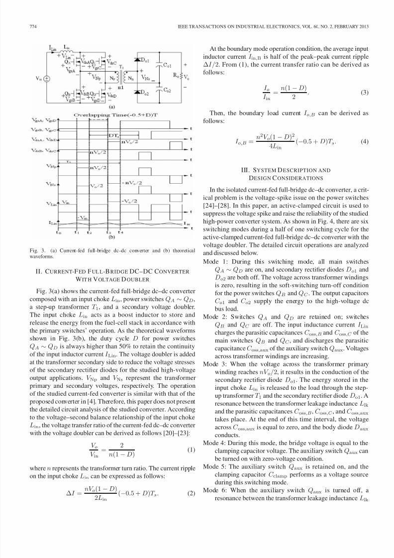
Fig. 3. (a) Current-fed full-bridge dc–dc converter and (b) theoreticalwaveforms.

II. CURRENT-F ED  F UL L-B RIDGE DC–DC CONVERTER

WIT H VOLTAGE D OUBLER

Fig. 3(a) shows the current-fed full-bridge dc–dc convertercomposed with an input choke Lin, power switches QA   ∼ QD,

a step-up transformer   T 1, and a secondary voltage doubler.

The input choke   Lin   acts as a boost inductor to store and

release the energy from the fuel-cell stack in accordance with

the primary switches’ operation. As the theoretical waveforms

shown in Fig. 3(b), the duty cycle   D   for power switches

QA  ∼ QD  is always higher than 50% to retain the continuity

of the input inductor current I Lin. The voltage doubler is added

at the transformer secondary side to reduce the voltage stresses

of the secondary rectifier diodes for the studied high-voltage

output applications.   V Np   and   V Ns   represent the transformer

primary and secondary voltages, respectively. The operation

of the studied current-fed converter is similar with that of theproposed converter in [4]. Therefore, this paper does not present

the detailed circuit analysis of the studied converter. According

to the voltage–second balance relationship of the input choke

Lin, the voltage transfer ratio of the current-fed dc–dc converter

with the voltage doubler can be derived as follows [20]–[23]:

V oV in

=  2

n(1 −D)  (1)

where n represents the transformer turn ratio. The current ripple

on the input choke Lin can be expressed as follows:

∆I  =  nV o(1 −D)2Lin

(−0.5 + D)T s.   (2)

At the boundary mode operation condition, the average input

inductor current  I in,B   is half of the peak–peak current ripple

∆I/2. From (1), the current transfer ratio can be derived as

follows:

I o

I in= n(1 −D)

2

  .   (3)

Then, the boundary load current   I o,B   can be derived as

follows:

I o,B  = n2V o(1 −D)2

4Lin

(−0.5 + D)T s.   (4)

III. SYSTEM D ESCRIPTION AND

DESIGN C ONSIDERATIONS

In the isolated current-fed full-bridge dc–dc converter, a crit-

ical problem is the voltage-spike issue on the power switches[24]–[28]. In this paper, an active-clamped circuit is used to

suppress the voltage spike and raise the reliability of the studied

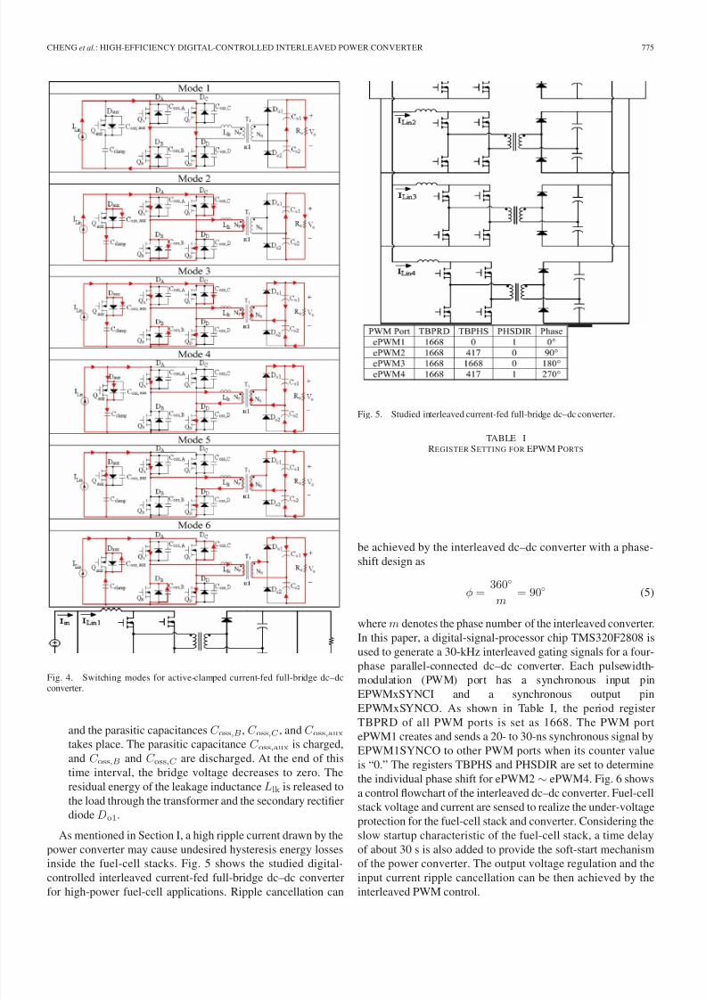
high-power converter system. As shown in Fig. 4, there are six

switching modes during a half of one switching cycle for the

active-clamped current-fed full-bridge dc–dc converter with the

voltage doubler. The detailed circuit operations are analyzed

and discussed below.

Mode 1: During this switching mode, all main switches

QA  ∼ QD  are on, and secondary rectifier diodes  Do1  and

Do2 are both off. The voltage across transformer windings

is zero, resulting in the soft-switching turn-off condition

for the power switches QB  and QC . The output capacitorsC o1   and   C o2   supply the energy to the high-voltage dc

bus load.

Mode 2: Switches   QA   and   QD   are retained on; switches

QB   and  QC   are off. The input inductance current   I Lincharges the parasitic capacitances C oss,B and C oss,C  of the

main switches  QB   and  QC , and discharges the parasitic

capacitanceC oss,aux of the auxiliary switch Qaux. Voltages

across transformer windings are increasing.

Mode 3: When the voltage across the transformer primary

winding reaches nV o/2, it results in the conduction of the

secondary rectifier diode  Do1. The energy stored in the

input choke  Lin   is released to the load through the step-up transformer T 1 and the secondary rectifier diode Do1. A

resonance between the transformer leakage inductance Llkand the parasitic capacitances C oss,B, C oss,C , and C oss,auxtakes place. At the end of this time interval, the voltage

across C oss,aux is equal to zero, and the body diode  Daux

conducts.

Mode 4: During this mode, the bridge voltage is equal to the

clamping capacitor voltage. The auxiliary switch Qaux can

be turned on with zero-voltage condition.

Mode 5: The auxiliary switch  Qaux   is retained on, and the

clamping capacitor  C clamp   performs as a voltage source

during this switching mode.

Mode 6: When the auxiliary switch   Qaux   is turned off, aresonance between the transformer leakage inductance Llk

7/25/2019 111. High Efficiency Digital Co

http://slidepdf.com/reader/full/111-high-efficiency-digital-co 3/8

CHENG et al.: HIGH-EFFICIENCY DIGITAL-CONTROLLED INTERLEAVED POWER CONVERTER 775

Fig. 4. Switching modes for active-clamped current-fed full-bridge dc–dcconverter.

and the parasitic capacitances C oss,B, C oss,C , and C oss,auxtakes place. The parasitic capacitance C oss,aux is charged,

and C oss,B   and  C oss,C  are discharged. At the end of this

time interval, the bridge voltage decreases to zero. The

residual energy of the leakage inductance Llk is released to

the load through the transformer and the secondary rectifier

diode Do1.

As mentioned in Section I, a high ripple current drawn by the

power converter may cause undesired hysteresis energy losses

inside the fuel-cell stacks. Fig. 5 shows the studied digital-

controlled interleaved current-fed full-bridge dc–dc converterfor high-power fuel-cell applications. Ripple cancellation can

Fig. 5. Studied interleaved current-fed full-bridge dc–dc converter.

TABLE IREGISTER SETTING FOR EPWM PORTS

be achieved by the interleaved dc–dc converter with a phase-

shift design as

φ = 360◦

m  = 90◦ (5)

where m denotes the phase number of the interleaved converter.

In this paper, a digital-signal-processor chip TMS320F2808 is

used to generate a 30-kHz interleaved gating signals for a four-

phase parallel-connected dc–dc converter. Each pulsewidth-

modulation (PWM) port has a synchronous input pin

EPWMxSYNCI and a synchronous output pinEPWMxSYNCO. As shown in Table I, the period register

TBPRD of all PWM ports is set as 1668. The PWM port

ePWM1 creates and sends a 20- to 30-ns synchronous signal by

EPWM1SYNCO to other PWM ports when its counter value

is “0.” The registers TBPHS and PHSDIR are set to determine

the individual phase shift for ePWM2 ∼ ePWM4. Fig. 6 shows

a control flowchart of the interleaved dc–dc converter. Fuel-cell

stack voltage and current are sensed to realize the under-voltage

protection for the fuel-cell stack and converter. Considering the

slow startup characteristic of the fuel-cell stack, a time delay

of about 30 s is also added to provide the soft-start mechanism

of the power converter. The output voltage regulation and the

input current ripple cancellation can be then achieved by theinterleaved PWM control.

7/25/2019 111. High Efficiency Digital Co

http://slidepdf.com/reader/full/111-high-efficiency-digital-co 4/8

776 IEEE TRANSACTIONS ON INDUSTRIAL ELECTRONICS, VOL. 60, NO. 2, FEBRUARY 2013

Fig. 6. Control flowchart of the interleaved current-fed full-bridge dc–dcconverter.

Fig. 7 shows an auxiliary-power design with Flyback topol-ogy to provide a 3.3-V voltage for the digital controller

and a 15-V voltage for the gate driver circuit. In practical

high-power applications, an energy-storage device such as the

Li-ion battery or ultracapacitor is usually used on the high-

voltage output dc bus of the power converter. Fig. 8 shows a CL

circuit design used in this paper to raise the system reliability. A

current-sensing resistor   Rsense   is series connected with the

load to sense the output current of the power converter. An

operational amplifier LM 358 is used as a current error amplifier

(CEA) to keep a constant-current (CC) output before the battery

voltage reaches to a given valueV s. Battery overcharging can be

then prevented, and the power converter can be also protected.

Fig. 9 shows the adopted CC/CV two-phase battery chargingscheme. When the battery voltage is below the threshold volt-

Fig. 7. Auxiliary-power design for the studied fuel-cell power converter.

Fig. 8. Schematics of a CL circuit.

Fig. 9. Two-phase battery charging curve design.

TABLE IICIRCUIT SPECIFICATIONS FOR A LABORATORY PROTOTYPE

age of   V s, a constant charging current is sustained. As the

battery voltage reaches  V s, a CV charging control is applied

to prevent overcharging.

IV. SIMULATION AND E XPERIMENTAL V ERIFICATIONS

A 10-kW laboratory prototype with circuit specificationsshown in Table II was built and tested to verify the feasibility of 

7/25/2019 111. High Efficiency Digital Co

http://slidepdf.com/reader/full/111-high-efficiency-digital-co 5/8

CHENG et al.: HIGH-EFFICIENCY DIGITAL-CONTROLLED INTERLEAVED POWER CONVERTER 777

TABLE IIISYSTEM SPECIFICATIONS OF THE USED  PEM FUE L-CELL  STACK

TABLE IVCIRCUIT PARAMETERS OF A 2.5-KW POWER  MODULE

Fig. 10. SIMPLIS simulation circuit for 2.5-kW power module.

Fig. 11. Simulated (a) gating signals and (b) circuit waveforms for a singlepower module.

the proposed scheme. The prototype converter is composed of 

four interleaved power modules with 2.5-kW rated power. As

shown in Table III, the voltage range of a 12-kW Heliocentris

Energy PEM fuel-cell stack is from 37 to 57 V at steady-state

operation. The stack voltage could rise up to 80 V at the

transient from heavy- to light-load conditions due to the slow

dynamic characteristics of the fuel-cell system. Table IV shows

the circuit parameters of the implemented 2.5-kW power

module. A SIMPLIS simulation circuit for the studied power

module is shown in Fig. 10. Fig. 11(a) and (b) shows the

simulated gating signals and circuit waveforms for a single2.5-kW power module at 55-V input voltage and rated load

Fig. 12. Simulated (a) interleaved gating signals and (b) ripple cancellationwaveforms for a four-phase dc–dc converter.

Fig. 13. Measured switching waveforms at Vin = 37 V and Po  = 2.5 kW.

Fig. 14. Measured switching waveforms at Vin = 57 V and Po  = 2.5 kW.

conditions. The simulated results are agreed with the theoretical

waveforms shown in Fig. 3(b). Fig. 12(a) shows the simulated

interleaved gating signals for a four-phase parallel-connected

dc–dc converter. From the simulation results in Fig. 12(b), it

can be observed that ripple cancellation on the fuel-cell stack 

current can be achieved by the interleaved gating signal with

90◦ phase shift.

Figs. 13 and 14 shows the measured waveforms at 37- and57-V input voltage conditions, respectively. Fig. 15 shows the

7/25/2019 111. High Efficiency Digital Co

http://slidepdf.com/reader/full/111-high-efficiency-digital-co 6/8

778 IEEE TRANSACTIONS ON INDUSTRIAL ELECTRONICS, VOL. 60, NO. 2, FEBRUARY 2013

Fig. 15. Interleaved waveforms of the four parallel-connected modules.

Fig. 16. Measured waveforms for input current ripple cancellation at Vin =

47 V and Po, total  = 5 kW.

Fig. 17. Measured soft-start waveforms at Vin = 47 V and Po, total  = 0→

5 kW.

interleaved waveforms of the four parallel-connected mod-

ules. As shown in Fig. 16, the ripple cancellation on the

input current can be achieved to reduce the hysteresis loss

of the fuel-cell stack. Fig. 17 shows the measured soft-start

waveforms of the studied power converter for high-power fuel-

cell applications. The measured signal VAUX is the auxiliary-

power supply voltage provided to the studied power converter

system. Considering the slow startup characteristic of the fuel-

cell stack, a time delay about 30 s is added to provide soft-

start mechanism of the power converter. After the startup

stage, the fuel-cell stack can be steadily operated, and the

converter circuit can be protected by the soft-start design. The

measured output current and voltage waveforms of the studieddc–dc converter are shown in Fig. 18(a) and (b). It can be

Fig. 18. Measured (a) output current and (b) output voltage waveforms of theinterleaved power converters at Vin  = 57 V and Po, total  = 10 kW.

Fig. 19. Measured efficiency of the interleaved power converter.

observed that a low voltage ripple is achieved by the studied

four-phase interleaved operation. Thus, less output capacitance

could be used. Moreover, in practical high-power applications,

an energy-storage device such as the Li-ion battery is usually

used on the high-voltage output dc bus of the power converter.

A low output-voltage ripple is preferred for the battery charg-

ing considerations. Fig. 19 shows the measured efficiency of 

the interleaved power converter under different input voltage

and load conditions. It can be observed that high conversion

efficiency can be achieved. The peak efficiency can be up

to 96.2%. Table V shows the circuit parameters for the used

active-clamped circuit. The switching waveforms for the active-

clamped current-fed dc–dc converter are measured and shownin Fig. 20. Fig. 21 shows the performance comparisons between

7/25/2019 111. High Efficiency Digital Co

http://slidepdf.com/reader/full/111-high-efficiency-digital-co 7/8

CHENG et al.: HIGH-EFFICIENCY DIGITAL-CONTROLLED INTERLEAVED POWER CONVERTER 779

TABLE VCIRCUIT PARAMETERS FOR THE USE D ACTIVE-CLAMPED CIRCUIT

Fig. 20. Measuredswitching waveforms for active-clamped current-fed dc–dcconverter at Vin  = 37 V and Po  = 1 kW.

Fig. 21. Performance comparisons between the current-fed converters withand without active-clamped circuit design.

the studied current-fed converters with and without the active-

clamped circuit design. It can be observed that the voltage

spike on power switches can be reduced about 60 V by the

active-clamped circuit at the rated load-power condition. The

system reliability can be then effectively improved. However,

the heavy-load efficiency drops about 2% due to the additional

power losses on the active-clamped circuit, whereas the light-

load efficiency can be raised about 1.5%.

V. CONCLUSION

This paper has presented a digital-controlled dc–dc converter

for high-power PEM fuel-cell applications. High-efficiency per-

formance and low-input-current ripple can be achieved by the

studied interleaved current-fed full-bridge dc–dc converter with

a secondary voltage-doubler topology. A 10-kW laboratory

prototype has been implemented and tested. The peak efficiency

of the prototype converter can be up to 96.2%. An active-

clamped technique has been studied to reduce the voltage spikeon the power switches for raising the system reliability.

REFERENCES

[1] C. A. Ramos-Paja, C. Bordons, A. Romero, R. Giral, and L. Martínez-Salamero, “Minimum fuel consumption strategy for PEM fuel cells,”

 IEEE Trans. Ind. Electron., vol. 56, no. 3, pp. 685–696, Mar. 2009.[2] B. Yuan, X. Yang, X. Zeng, J. Duan, J. Zhai, and D. Li, “Analysis and

design of a high step-up current-fed multiresonant dc–dc converter withlow circulating energy and zero-current switching for all active switches,”

 IEEE Trans. Ind. Electron., vol. 59, no. 2, pp. 964–978, Feb. 2012.

[3] A. K. Rathore, A. K. S. Bhat, and R. Oruganti, “Analysis, design andexperimental results of wide range ZVS active-clamped L-L type current-fed dc/dc converter for fuel cells to utility interface,”   IEEE Trans. Ind.

 Electron., vol. 59, no. 1, pp. 473–485, Jan. 2012.[4] X. Kong and A. M. Khambadkone, “Analysis and implementation of 

a high efficiency, interleaved current-fed full bridge converter for fuelcell system,”  IEEE Trans. Power Electron., vol. 22, no. 2, pp. 543–550,Mar. 2007.

[5] J. M. Kwon, E. H. Kim, B. H. Kwon, and K. H. Nam, “High-efficiencyfuel cell power conditioning system with input current ripple reduction,”

 IEEE Trans. Ind. Electron., vol. 56, no. 3, pp. 826–834, Mar. 2009.[6] M. Nymandand M. A. E. Andersen,“High-efficiency isolated boostdc–dc

converter for high-power low-voltage fuel-cell applications,” IEEE Trans. Ind. Electron., vol. 57, no. 2, pp. 505–514, Feb. 2010.

[7] N. Mutoh and Y. Nakano, “Dynamics of front-and-rear-wheel-independent-drive-type electric vehicles at the time of failure,”   IEEE 

Trans. Ind. Electron., vol. 59, no. 3, pp. 1488–1499, Mar. 2012.[8] S. Espiari and M. Aleyaasin, “Transient response of PEM fuel cells duringsudden load change,” in   Proc. IEEE Int. Energy Conf. Exhib., 2010,pp. 211–216.

[9] D. M. Ali, “A simplified dynamic simulation model (prototype) for astand-alone polymer electrolyte membrane (PEM) fuel cell stack,” inProc. 12th Int. Middle-East Power Syst. Conf., 2008, pp. 480–485.

[10] J. M. Lee and B. H. Cho, “A dynamic model of a PEM fuel cell system,”in Proc. 24th Annu. IEEE APEC , 2009, pp. 720–724.

[11] Z. Zhang, W. J. Lee, and M. Liu, “PEM fuel cell and battery hybridpower supply system design based on fuel flow rate control,” in  Proc. 4th

 Int. Conf. Elect. Utility Deregulation Restruct. Power Technol., 2011,pp. 284–291.

[12] W. A. Adams, J. D. Blair, K. R. Bullock, C. L. Gardner, and L. Li,“Cost/benefit analyses of a new battery pack management technique fortelecommunication applications: future directions with fuel cell/batterysystems,” in   Proc. 26th Annu. Int. Telecommun. Energy Conf., 2004,

pp. 73–82.[13] F. Ciancetta, A. Ometto, and N. Rotondale, “Analysis of PEM fuel

cell–supercapacitor–battery pack system during standard cycle,” inProc. Int. Symp. Power Electron. Elect. Drives Autom. Motion, 2010,pp. 1286–1290.

[14] W. Lee, B. M. Han, and H. Cha, “Battery ripple current reduction ina three-phase interleaved dc–dc converter for 5 kW battery charger,” inProc. IEEE Energy Convers. Congr. Expo., 2011, pp. 3535–3540.

[15] M. F. M. Elias, K. M. Nor, N. A. Rahim, and A. K. Arof, “Lithium-ionbattery charger for high energy application,” in   Proc. Nat. Power Eng.Conf., 2003, pp. 283–288.

[16] E. S. Park, S. J. Choi, J. M. Lee and, and B. H. Cho, “A soft-switchingactive-clamp scheme for isolated full-bridge boost converter,” in  Proc.19th Annu. IEEE APEC , 2004, vol. 2, pp. 1067–1070.

[17] H. Cha, J. Choi, and P. N. A. Enjeti, “Three-phase current-fed dc/dcconverter with active clamp for low-dc renewable energy sources,”  IEEE Trans. Power Electron., vol. 23, no. 6, pp. 2784–2793, Nov. 2008.

[18] O. A. Ahmed and J. Bleijs, “Optimized active-clamp circuit design for anisolated full-bridge current-fed dc–dc converter,” in  Proc. 4th Int. Conf.Power Electron. Syst. Appl., 2011, pp. 1–7.

[19] S. Lee, J. Park, and S. Choi, “A three-phase current-fed push–pull dc–dcconverter with active clamp for fuel cell applications,” IEEE Trans. Power 

 Electron., vol. 26, no. 8, pp. 2266–2277, Aug. 2011.[20] A. I. Pressman,   Switching Power Supply Design, 2nd ed. New York:

McGraw-Hill, 1999.[21] M. Bertoluzzo and G. Buja, “Development of electric propulsion systems

for light electric vehicles,”   IEEE Trans. Ind. Informat., vol. 7, no. 3,pp. 428–435, Aug. 2011.

[22] A. Y. Sendjaja and V. Kariwala, “Decentralized control of solid oxide fuelcells,” IEEE Trans. Ind. Informat., vol. 7, no. 2, pp. 163–170, May 2011.

[23] M. P. Kazmierkowski, M. Jasinski, and G. Wrona, “DSP-based control of grid-connected power converters operating under grid distortions,”  IEEE Trans. Ind. Informat., vol. 7, no. 2, pp. 204–211, May 2011.

[24] Y. S. Lai, C. A. Yeh, and K. M. Ho, “A family of predictive digital-controlled PFC under boundary current mode control,”  IEEE Trans. Ind. Informat., vol. 8, no. 3, pp. 448–458, Aug. 2012.

7/25/2019 111. High Efficiency Digital Co

http://slidepdf.com/reader/full/111-high-efficiency-digital-co 8/8

780 IEEE TRANSACTIONS ON INDUSTRIAL ELECTRONICS, VOL. 60, NO. 2, FEBRUARY 2013

[25] S. Dasgupta, S. N. Mohan, S. K. Sahoo, and S. K. Panda, “A plug andplay operational approach for implementation of an autonomous-micro-grid system,” IEEE Trans. Ind. Informat., vol. 8, no. 3, pp. 615–629, Aug2012.

[26] H. H. Wu, A. Gilchrist, K. Sealy, and D. Bronson, “A high efficiency5 kW inductive charger for EVs using dual side control,”  IEEE Trans.

 Ind. Informat., vol. 8, no. 3, pp. 585–595, Aug 2012.[27] G. Buticchi, D. Barater, E. Lorenzani, and G. Franceschini, “Digital

control of actual grid-connected converters for ground leakage currentreduction in PV transformerless systems,”   IEEE Trans. Ind. Informat.,vol. 8, no. 3, pp. 563–572, Aug 2012.

[28] A. Al Nabulsi and R. Dhaouadi, “Efficiency optimization of a DSP-basedstandalone PV system using fuzzy logic and dual-MPPT control,”   IEEE Trans. Ind. Informat., vol. 8, no. 3, pp. 573–584, Aug 2012.

Shih-Jen Cheng  was born in Kinmen, Taiwan, in1981. He received the B.E. degree in electrical engi-neering from Kao Yuan University, Kaohsiung,Taiwan, in 2005, the M.S. degree in electrical en-gineering from Chung Yuan Christian University,Chungli, Taiwan, in 2007, and the Ph.D. degreein electronic engineering from the National TaiwanUniversity of Science and Technology (NTUST),Taipei, Taiwan, in 2010.

He is currently a Postdoctoral ResearchFellow with the Power Electronics Technology

Center, NTUST. His research interests are light-emitting diode driver, field-programmable gate array, and digital-signal-processing control applications inrenewable-energy applications.

Yu-Kang Lo  (M’96) was born in Chiayi, Taiwan,in 1969. He received the B.S. and Ph.D. degreesin electrical engineering from the National TaiwanUniversity, Taipei, Taiwan, in 1991 and 1995,respectively.

Since 1995, he has been with the Faculty of the Department of Electronic Engineering, NationalTaiwan University of Science and Technology,Taipei, Taiwan, where he is currently a Professor and

in charge of the Power Electronic Laboratory andPower Electronics Technology Center. His research

interests include the design and analysis of a variety of switch-mode powerconverters and power factor correctors.

Dr. Lo is a member of the IEEE Power Electronics and Industrial ElectronicsSocieties.

Huang-Jen Chiu (M’00–SM’09) was born in I-Lan,Taiwan, in 1971. He received the B.E. and Ph.D.degrees in electronic engineering from the Na-tional Taiwan University of Science and Technol-ogy (NTUST), Taipei, Taiwan, in 1996 and 2000,respectively.

From August 2000 to July 2002, he was an As-sistant Professor with the Department of Electronic

Engineering, I-Shou University, Kaohsiung, Taiwan.From August 2002 to July 2006, he was with theDepartment of Electrical Engineering, Chung Yuan

Christian University, Chungli, Taiwan. Since August 2006, he has been withthe Department of Electronic Engineering, NTUST, where he is currently aProfessor. His research interests include high-efficiency light-emitting diodedrivers, soft switching techniques, electromagnetic compatibility (EMC) issues,power factor correction (PFC) topologies, electronic ballast, and digital-signal-processing control in renewable-energy applications.

Dr. Chiu was a recipient of several awards, including the Young ResearcherAward in 2004 from the National Science Council, Taiwan, the OutstandingTeaching Award and the Excellent Research Award in 2009 from the NTUST,and the Y. Z. Hsu Scientific Paper Award in 2010. He is a Senior Member of the IEEE Power Electronics Society.

Shu-Wei Kuo was born in Tainan, Taiwan, in 1986.He received the B.E. degree in electronicengineeringin 2008 from the National Taiwan University of Science and Technology, Taipei, Taiwan, where heis currently working toward the Ph.D. degree.

His research interests include electric energy-saving/storage technology, high-power dc/dc con-verter, and fuel-cell power application.


Recommended