1112 IEEE TRANSACTIONS ON MICROWAVE THEORY AND TECHNIQUES, VOL. 56, NO. 5, MAY 2008
Modal Propagation and Excitationon a Wire-Medium Slab
Paolo Burghignoli, Senior Member, IEEE, Giampiero Lovat, Member, IEEE,Filippo Capolino, Senior Member, IEEE, David R. Jackson, Fellow, IEEE, and Donald R. Wilton, Life Fellow, IEEE
Abstract—A grounded wire-medium slab has recently beenshown to support leaky modes with azimuthally independentpropagation wavenumbers capable of radiating directive omni-directional beams. In this paper, the analysis is generalized towire-medium slabs in air, extending the omnidirectionality prop-erties to even modes, performing a parametric analysis of leakymodes by varying the geometrical parameters of the wire-mediumlattice, and showing that, in the long-wavelength regime, surfacemodes cannot be excited at the interface between the air andwire medium. The electric field excited at the air/wire-mediuminterface by a horizontal electric dipole parallel to the wires isalso studied by deriving the relevant Green’s function for thehomogenized slab model. When the near field is dominated by aleaky mode, it is found to be azimuthally independent and almostperfectly linearly polarized. This result, which has not been previ-ously observed in any other leaky-wave structure for a single leakymode, is validated through full-wave moment-method simulationsof an actual wire-medium slab with a finite size.
Index Terms—Leaky modes, metamaterials, near field, planarslab, wire medium.
I. INTRODUCTION
THE 1-D wire medium consists of a periodic arrangementof thin perfectly conducting cylinders (wires), infinitely
long and parallel, embedded inside a homogeneous host dielec-tric medium. Such an artificial medium, also known as a roddedmedium, has been known since the 1950s to be described in thelong-wavelength regime by a scalar permittivity with a plasma-like dispersion behavior for waves having the electric field po-larized along the axis of the wires [1].
As can easily be predicted from the directionality of the wirelattice, the 1-D wire medium is uniaxial for waves with arbi-trary polarization. A far less trivial property, first pointed outin [2] and [3], is the presence of spatial dispersion even in thelarge wavelength regime, i.e., the nonlocal nature of the elec-trical response of the wire medium. This feature, also presentin more complex 2-D and 3-D wire arrangements [4], [5], hasremarkable consequences on the propagation of plane waves in-side an unbounded 1-D wire medium: for instance, in addition
Manuscript received September 1, 2007; revised December 19, 2007.P. Burghignoli is with the Department of Electronic Engineering, “La
Sapienza” University of Rome, 00184 Rome, Italy (e-mail: [email protected]).
G. Lovat is with the Department of Electrical Engineering, “La Sapienza”University of Rome, 00184 Rome, Italy (e-mail: [email protected]).
F. Capolino is with the Department of Information Engineering, Universityof Siena, 53100 Siena, Italy (e-mail: [email protected]).
D. R. Jackson and D. R. Wilton are with the Department of Electrical andComputer Engineering, University of Houston, Houston, TX 77204-4005 USA(e-mail: [email protected]; [email protected]).
Digital Object Identifier 10.1109/TMTT.2008.921657
Fig. 1. (a) Wire-medium slab in air with the relevant coordinate axes.(b) Transverse view of the wire-medium slab with the relevant geometricalparameters.
to the usual ordinary and extraordinary waves existing in anyuniaxial medium ( and with respect to the wire direc-tion, respectively), an additional wave may exist, prop-agating in the direction of the wires; furthermore, for extraor-dinary plane waves, the propagation wavenumber does not de-pend on the direction of propagation of the wave, i.e., the isofre-quency surfaces in the wavenumber space are spherical [3]. Thepresence of spatial dispersion poses a formidable challenge inthe solution of boundary-value problems with nonplanar bound-aries. Even in the presence of purely planar interfaces, addi-tional boundary conditions may be required when the wires arenot purely parallel to the interfaces [6]. Propagation of wavesin bounded wire-medium structures has been considered in [7]and [8].
In this paper, we consider the problem of modal excitationand propagation along a canonical planar waveguide, a slab infree space, made of a 1-D wire medium with wires parallel tothe air–slab interfaces (see Fig. 1, where the relevant geomet-rical parameters and the adopted coordinate system are alsoshown). Recently, certain properties of a grounded configura-tion of such a slab have been studied, excited by a simple electricdipole source placed inside the wire-medium and oriented par-allel to the wires [9]. For frequencies slightly above the plasmafrequency, where the relative permittivity is positive but small,it has been shown that the structure is capable of producingnarrow-beam radiation patterns. Depending on the frequency,the beam may be either a pencil beam at broadside, or a conicalbeam at a particular scan angle. It was shown in [10] and [11]that this directive radiation is due to the excitation of a leaky
Authorized licensed use limited to: Univ of Calif Irvine. Downloaded on October 21, 2008 at 21:42 from IEEE Xplore. Restrictions apply.
BURGHIGNOLI et al.: MODAL PROPAGATION AND EXCITATION ON WIRE-MEDIUM SLAB 1113
mode supported by the grounded slab having a wavenumber in-dependent of its azimuthal angle of propagation.
The aim of this paper is twofold. First, to generalize the anal-ysis of modal propagation at arbitrary angles to the case of awire-medium slab in air, considering both even and odd modes,performing a parametric analysis of the properties of the leakymodes, and showing that surface (either ordinary or plasmon-like) modes cannot propagate along the slab in the long-wave-length regime. Second, to consider the excitation of a domi-nant leaky mode by a horizontal dipole source parallel to thewires, and to study the properties of the resulting near field atthe air–slab interface, adopting both a homogeneous model anda full-wave method of moments (MoM) approach.
This paper is organized as follows. In Section II, the ho-mogenized model of the wire-medium slab is presented alongwith the relevant transverse equivalent networks; these allowfor a discussion of the properties of surface and leaky modesand of the electric field excited at the air–slab interface by ahorizontal electric dipole. In Section III, the adopted full-wavemodal analysis based on the MoM in the spatial domain is de-scribed. In Section IV, numerical results for the propagation ofleaky modes and for the features of the electric field excited bythe dipole source are presented. Finally, in Section V, conclu-sions are drawn.
II. HOMOGENIZED MODEL AND TRANSVERSE
EQUIVALENT NETWORK
A. Homogenized Medium
The wire medium shown in Fig. 1 is anisotropic for electro-magnetic waves with an arbitrary polarization, requiring the useof a uniaxial permittivity dyadic with optical axis directed par-allel to the wire ( ) axis when it is homogenized at wavelengthssufficiently larger than the wire spacing. Actually, as shown in[2] and [3], not only anisotropy, but also spatial dispersion needsto be included in a homogenized description of the medium,even for large wavelengths. The effective permittivity dyadicthus depends on both the frequency and wavenumber, and forthin wires [i.e., ] and in the large-wavelengthlimit (i.e., , with the free-space wave-length), it reads
(1)
where is the relative permittivity of the medium hostingthe wires (for the structures considered here, air is assumedas the host medium, i.e., ), is the free-spacewavenumber, is the plasma wavenumber, and is thewavenumber along the wire axis. Here and in the following,boldface symbols denote vectors, while , , and denoteunit vectors along the -, -, and -directions, respectively. Theplasma wavenumber is given by (see [12])
(2)
Fig. 2. Transverse equivalent network representations of a wire-medium slabin air with thickness �� for: (a) odd �� modes and (b) even �� modes.(c) Transverse equivalent network for a grounded wire-medium slab as in (a)with thickness �, excited by a horizontal electric dipole parallel to the wiresplaced at a distance � from the ground plane.
where , , and
(3)
In particular, for square lattices, i.e., when ( ),there results , while when or
, there results .
B. Modal Dispersion Equations andSurface-Wave Suppression
The field of a leaky mode propagating on a wire-mediumslab, as in Fig. 1, with complex wavenumberat an angle has an exponential dependence on the - and
-coordinates with wavenumbers and. The electromagnetic field inside the air region and
the wire-medium slab is decomposed into and com-ponents, which can be represented through equivalent transmis-sion lines along (details are given in the Appendix).
The (ordinary) polarization sees an isotropic equivalentmedium equal to the host medium (air). Furthermore, as shownin [10] and [11], at the air/wire-medium interface, no /coupling occurs when the host medium is air. Therefore,and polarizations are decoupled and modal solutionsare not supported by the wire-medium slab. (For completeness,we note here that nonmodal solutions exist, which are ac-tually plane waves propagating in free space at arbitraryangles in the -plane with no variation).
The study of modes in a slab of thickness is per-formed using the transverse equivalent networks shown inFig. 2(a) and (b) for odd and even modes; by symmetry, theplane is equivalent to a perfect electric conductor for odd
Authorized licensed use limited to: Univ of Calif Irvine. Downloaded on October 21, 2008 at 21:42 from IEEE Xplore. Restrictions apply.
1114 IEEE TRANSACTIONS ON MICROWAVE THEORY AND TECHNIQUES, VOL. 56, NO. 5, MAY 2008
modes and to a perfect magnetic conductor for even modes.The transverse equivalent network parameters are
(4)
and
(5)
where is the free-space characteristic impedance. As con-cerns the value of the parameter , i.e., the equivalent thick-ness of the homogenized slab, we have adopted here the choice
, where is the number of wire layers along the -di-rection; although quite natural [13], this choice has no rigorousjustification, but it will be seen in Section IV to yield results ingood agreement with the full-wave simulations.
The modal dispersion equations for the extraordinary evenand odd modes can be obtained by enforcing the conditionof resonance on the transverse equivalent networks shown inFig. 2(a) and (b), i.e.,
even modes
odd modes (6)
From (6) and (5), it can be seen that a possible solution is, which corresponds to having . The casecorresponds to waves, and represents a special
case for which the permittivity model in (1) breaks down for apractical medium since this equation predicts thatfor such waves (for an idealized medium that obeys (1), a con-tinuous nonmodal spectrum of waves may be shown toexist [3]). For , from (4) and (5), the dispersion equa-tions (6) can be written as
even modes
odd modes (7)
which turn out to be independent of the propagation angle (andequal to the dispersion equation for modes of an ordinaryisotropic slab with ). This interesting propertyarises from the fact that the dependence in both of the char-acteristic impedance terms of (5) are the same, and hence, thisdependence cancels out when these terms are inserted into thetransverse resonance equation.
From the omnidirectionality of modal propagation, importantconclusions can be drawn about the existence of bound waves(surface waves) on the wire-medium slab with air as the hostmedium. Let us consider first propagation in the direction or-thogonal to the wire aixs. By symmetry, the electromagneticfield of modes propagating in this direction has nonzerocomponents , , and (so that these modes can also beclassified as ); from (1), it is then found that such modessee the homogenized medium as an isotropic medium with a
plasma-like scalar relative permittivity . Now,when (i.e., the frequency is lower than the plasma fre-quency), it follows that , i.e., the medium is epsilon nega-tive; therefore, (i.e., ) surface waves cannot propagate(a proof may be found in [14] for odd modes with the exten-sion to even modes being straightforward). On the other hand,when (i.e., the frequency is higher than the plasma fre-quency), the medium has a relative permittivity that is positive,but lower than one, so that total reflection cannot occur at theslab–air interface, and again, no surface waves may exist.
Therefore, as long as the homogenization process is valid,surface waves cannot propagate orthogonally to the wires.By virtue of the omnidirectionality of modal propagationestablished above, it can be concluded that surface wavescannot propagate at any frequency and at any angle along awire-medium slab in air. The only type of guided mode thatmay, therefore, exist on the homogenized wire medium slab isa leaky wave. The properties of such a mode are exploredin Section IV-A.
C. Electric Field at the Air–Slab Interface
Assuming now the presence of a horizontal infinitesimal elec-tric dipole parallel to the wires, we wish to calculate the elec-tric field at the air–slab interface, still assuming a homogenizedmodel for the slab. Although a rigorous calculation of such anear field would require a full-wave treatment of the interac-tion between the aperiodic dipole source and its periodic wire-medium environment, e.g., through the array scanning method[15], the results obtained with the homogenized model may helpin gaining physical insight into the radiation mechanism of thestructure. Furthermore, as will be shown in Section IV-B, whenthe near field is dominated by a leaky mode, the homogenizedresults are in good agreement with those obtained via a rigorousfull-wave analysis.
The field excited by a dipole parallel to the metal wires ispurely (since by reciprocity neither nor fieldscan be excited), and its tangential components and at
can be calculated from the spectral form of Maxwell’sequations (21) and (22) and from (27) as
(8)
where [A] for an elemental electric dipole directed along. The equivalent voltage at due to a 1-A
equivalent impressed current at [see Fig. 2(c)] is givenby
(9)It is interesting to note that
(10)
Authorized licensed use limited to: Univ of Calif Irvine. Downloaded on October 21, 2008 at 21:42 from IEEE Xplore. Restrictions apply.
BURGHIGNOLI et al.: MODAL PROPAGATION AND EXCITATION ON WIRE-MEDIUM SLAB 1115
where is the equivalent voltage due to a 1-A currentsource for an isotropic slab with relative permittivity
. Since, as is well known, depends only on the radialwavenumber , the anisotropy of the structure appears only inthe factor in the numerator of (9).
The tangential components of the electric field at canbe calculated in the spatial domain by inverse Fourier trans-forming (8), i.e.,
(11)
By performing the standard change of variables in the trans-verse plane from rectangular to polar in both the spectral andspatial domains [17], from (11) and (10) we obtain for the elec-tric field excited at the air–slab interface by the considered ele-mental source
(12)
and
(13)The integrands in (12) and (13) have pole singularities in thecomplex plane corresponding to the leaky modes supportedby the structure, and branch-point singularities of square-roottype at , which give rise to the space-wave contribu-tion [17]. Moreover, there is a branch point at the origin due tothe presence of the Hankel functions; however, with a suitablechoice of the relevant branch cut (along the imaginary axis), thisbranch cut lies along the usual Sommerfeld branch cut for thewavenumber [17], and hence, is of no concern in what follows.
As is well known, by deforming the original integration pathalong the real axis to a vertical pair of paths through the branchpoint at , the components of the total field in (12) and (13) canbe decomposed as the sum of a surface-wave field, a leaky-wavefield, and a space-wave field [17]
(14)
The leaky-wave field is given by the sum of the residue con-tributions at the complex poles, which are captured by theabove-mentioned integration-path deformation; moreover, inthe present case, the surface-wave field is absent so that
(15)
where is equal to 1 if the th leaky-wave pole is captured,otherwise it is zero. When only one term in the sum is signifi-cant, the corresponding leaky mode is said to be dominant. Fi-nally, the space-wave field is given by the integral along theabove-mentioned vertical paths through the branch point at .
The contribution of the dominant leaky mode to the total fieldexcited by the considered source is evaluated as the residue con-tribution to the integrals in (12) and (13) at the dominant com-plex leaky-wave pole (i.e., the one with thelowest attenuation constant ) and it has the expression
(16)
and
(17)
where .
Numerically, the integrations in (12) and (13) are per-formed by suitably deforming the integration path to avoid thebranch-point singularity located at on the real axis andby adopting standard adaptive quadrature routines. The residueterm in (16) and (17) can instead be evaluated by numericalintegration of the function along a small circleenclosing the relevant leaky-wave pole . Finally, thespace-wave field is calculated through the numerical integrationof the integrand of (12) and (13) along a vertical pair of pathsthrough the branch point at ; for large distances fromthe source, this path becomes a steepest descent path alongwhich the integrand decays exponentially fast [17].
It is noted that in the second addend in (16), as well asthe cross-polarized term in (17), the terms in front of theHankel functions are proportional to for small values of
. Note that when the leaky mode has a small propagationwavenumber so that , the weighting coefficientsfrom the terms are such that the cross-polarized field ofthe leaky mode is negligible. The wavenumber will be smallwhen the permittivity is small (corresponding to a weaklyattenuated leaky mode that radiates near broadside).
The space-wave field excited by the source is mainly asso-ciated with the branch point at , and hence, is notsmall for this wave. Therefore, the space-wave field has signif-icant cross-polarization. In fact, this field will mainly be polar-ized perpendicular to the wires since the wires will act to shortout the parallel component of the field for this wave. However,if the leaky mode is dominant, the overall field will exhibit agood polarization purity. This will be the case when the permit-tivity is small, as will be demonstrated later in the results.These points explain why the radiation patterns in [9]–[11] havea good polarization purity.
III. FULL-WAVE MODAL ANALYSIS
Leaky-wave propagation on the wire-medium slab with airas the host medium is also studied here by means of a rigorous
Authorized licensed use limited to: Univ of Calif Irvine. Downloaded on October 21, 2008 at 21:42 from IEEE Xplore. Restrictions apply.
1116 IEEE TRANSACTIONS ON MICROWAVE THEORY AND TECHNIQUES, VOL. 56, NO. 5, MAY 2008
formulation based on the MoM in the spatial domain. The peri-odicity of the structure allows for considering one spatial periodonly (unit cell), thus requiring the use of a periodic (free-space)Green’s function . Since the latter is known to be representedby a slowly convergent series, an effective numerical accelera-tion procedure has been implemented based on the Ewald sum-mation technique [16].
As mentioned in Section II, when the host medium is air,and polarizations do not couple, and they can be studiedseparately. Furthermore, for very thin wires (as the ones con-sidered here), only the polarization is of interest since, inthis limit, the polarization does not interact with the wiresand propagates as in free space (and therefore no modesexist). It should also be noted that for the discrete wire-mediumstructure shown in Fig. 1, multiconductor transmissionline modes may exist, which are different than the modalradially propagating solutions that are examined here. However,such modes will not be considered in the following since theycannot be excited by an electric dipole that is parallel to thewires (the type of source considered here). This follows fromreciprocity since the dipole is orthogonal to the electric field ofthese modes.
Due to the exponential dependence of the modal field on the- and -coordinates and the invariance of the structure along
the -direction, the electromagnetic problem is reduced to a 2-Done in the -plane. Moreover, for the polarization of in-terest, the azimuthal component of the current along the wiresis identically zero and the MoM unknown is thus the longitu-dinal component . The electric field integral equation (EFIE)for wave propagation at an arbitrary angle reads (see [11, Ap-pendix])
(18)where indicates the union of the boundaries of the wire crosssections in a unit cell, while and
are the observation and source vectors in the -plane, re-spectively. Since , from (18) it is immediatelyseen that the EFIE for wave propagation at an arbitrary angle
is equivalent to that at an angle of (propagation or-thogonal to the wires, i.e., no variation of currents or fields with
) provided that the free-space wavenumber is replaced by
a scaled effective wavenumber . Finally, the
propagation along determines the phasingused in the periodic Green’s function .
The EFIE can be discretized using subdomain (e.g., piece-wise constant) basis functions and a Galerkin testing proce-dure. However, because of the simple (circular) cross sectionof the wires, entire-domain basis functions can also be effec-tively used, dramatically reducing the computational effort andthe size of the MoM matrix. In particular, exponential functionshave been used to expand the unknown current density sothat for each cylinder
(19)
where are polar coordinates in the -plane centered onthe wire axis, is the wire radius, and are the unknownexpansion coefficients. Since the wires are very thin, typicallyvery few basis functions are needed to obtain an accurate repre-sentation of the current density; in the simulations, three basisfunctions (i.e., ) have been used, although usingonly the basis function would yield sufficiently accu-rate results. Once the EFIE has been discretized, the complexwavenumber of the leaky modes supported bythe wire-medium slab has then been determined by searchingfor the zeros of the determinant (as a function of ) of the co-efficient matrix of the resulting linear system.
As long as the period is much smaller than the wavelengthand (1), the leaky mode has a fundamental Floquet wave thatis improper (exponentially increasing in the vertical -direc-tion), while all other Floquet waves are proper (exponentiallydecreasing in the direction); this means that, in the calculationof the spectral part of the periodic Green’s function in the Ewaldrepresentation, the determination of the square root defining the
th transverse harmonic
(20)
has to be correctly chosen. In particular, for thefundamental zeroth harmonic and for all theother harmonics (i.e., ) [18].
IV. NUMERICAL RESULTS
A. Parametric Analysis of Leaky Modes
To validate the conclusions reached with the homogenizedmodel of the wire-medium slab, a parametric investigation ofmodal propagation has been performed through the rigorousmoment-method approach described in Section III.
In Fig. 3, dispersion curves for the fundamental even ( )and odd ( ) modes are reported for propagation orthogonal( ) and parallel ( ) to the wires (black lines), alongwith the corresponding curves obtained by means of the homog-enized model (gray lines). (The notation even/odd refers to thevariation of the transverse electric field about the center of theslab. At cutoff, the mode has one half cycle of variationvertically within the substrate, while the mode has onecycle of variation.) It can be seen that the full-wave results forboth the normalized phase and attenuation constants are almostsuperimposed with the homogenized-model results. In partic-ular, for propagation parallel to the wires, the agreement is in-dependent of frequency in the range shown, whereas it tends toslightly deteriorate as the frequency increases for propagationorthogonal to the wires.
The frequencies for which (i.e., 6.8 GHz for themode and 7.4 GHz for the mode) correspond to fre-
quencies of optimum broadside radiation from the leaky modes[19]. At these frequencies, the electrical thickness of the slab( ) is 0.45 and 0.90, respectively. The slab is essentiallyoperating as a leaky parallel-plate waveguide, where the air re-gion surrounding the slab presents a low impedance relative tothe high-impedance slab material (which has a low permittivity).
Authorized licensed use limited to: Univ of Calif Irvine. Downloaded on October 21, 2008 at 21:42 from IEEE Xplore. Restrictions apply.
BURGHIGNOLI et al.: MODAL PROPAGATION AND EXCITATION ON WIRE-MEDIUM SLAB 1117
Fig. 3. Dispersion curves for the dominant even (�� ) and odd (�� ) leakymodes supported by a wire-medium slab in air, propagating in the directions: (a)� � � and (b) � � �� . Solid lines: phase constant. Dashed lines: attenuationconstant. Black lines: full-wave MoM results. Gray lines: homogenized-modelresults. Parameters: � � � � �� mm, � � ��� mm, � � � (homogenizedparameters: �� � �� mm, � � ����� rad/m).
For an ideal parallel-plate waveguide (with top and bottom metalwalls), the electrical thickness of the waveguide would be ex-actly 0.5 and 1.0 for the and modes at cutoff, withcutoff corresponding to radiation at broadside (when radiationis allowed to escape from the waveguide so that the waveguidebecomes leaky).
The degree of omnidirectionality of modal propa-gation achieved in actual periodic wire-medium slabscan be appreciated in Fig. 4. Here, the relative errors
and for the phase and attenuation constants, de-fined as and
, are reported as a function of thepropagation angle for both the fundamental even and oddmodes of a structure, as in Fig. 3. It can be seen that for lowfrequencies (e.g., at GHz), the maximum relative errorin the entire angular range is less than 1%, indicating a veryhigh degree of omnidirectionality of modal propagation. In thehigh-frequency range (e.g., at GHz), the maximumrelative error for the attenuation constant is still also less than2%, while the attenuation constant starts to lose its isotropiccharacter (although its maximum relative error is less than10%).
Fig. 4. Illustration of the degree of omnidirectionality of modal propagation.The relative errors � and � (defined as the normalized difference betweenthe values of the phase and attenuation constants at an arbitrary propagationangle � and those at � � �� ) are reported as a function of � at two dif-ferent frequencies for a structure, as in Fig. 3. (a) Fundamental�� even mode.(b) Fundamental�� odd mode. Black lines: 8 GHz. Gray lines: 13 GHz. Solidlines: � . Dashed lines: � .
The effect of changing the spatial periods of the wire latticehas also been investigated, maintaining the condition of thinwires [i.e., ]. In Fig. 5, a comparison betweenfull-wave and homogenized results is presented for the funda-mental odd mode of a structure, as in Fig. 3, with the spa-tial period reduced from 10 to 3 mm, propagatingin the principal directions and . As expected, thedispersion curves are shifted towards a higher frequency rangewith respect to those in Fig. 3; in fact, one effect of reducingthe spatial period in a square lattice is to increase the plasmawavenumber. Moreover, although the spatial period is smallerwith respect to that of the structure considered in Fig. 3, the pe-riod-wavelength ratio has increased so that the accuracy of thehomogenized model is decreased; however, overall it remainsvery good. The small difference between the solid black curves( and ) shows that the degree of omnidirection-ality also tends to reduce at high frequencies (above approxi-mately 40 GHz).
It is also interesting to consider the effect of letting the spatialperiods along the - and -directions be different, i.e., ,maintaining fixed the other parameters (i.e., the wire radius
Authorized licensed use limited to: Univ of Calif Irvine. Downloaded on October 21, 2008 at 21:42 from IEEE Xplore. Restrictions apply.
1118 IEEE TRANSACTIONS ON MICROWAVE THEORY AND TECHNIQUES, VOL. 56, NO. 5, MAY 2008
Fig. 5. Effect of reducing the period of the wire medium. Dispersion curveof the fundamental �� odd leaky mode of a structure, as in Fig. 3, with� � � � � � � mm. Solid lines: phase constant. Dashed lines: attenua-tion constant.
Fig. 6. Effect of different wire spacings along � and � in the wire-medium slab.Dispersion curves of the fundamental�� odd mode supported by a structure,as in Fig. 3, are shown for different values of the spatial periods � and � . Solidlines: phase constant. Dashed lines: attenuation constant.
and the number of wire layers ). In Fig. 6, dispersion curvesare shown for the fundamental odd mode propagating at
on four different wire-medium slabs, two with a squarelattice ( mm and mm) and two witha rectangular lattice ( mm, mm and mmand mm). In all cases, the simulations are in verygood agreement with the homogenized results (not reported forclarity). In particular, the frequencies at which are alwayswell predicted by the simple formula[19], where is the equivalent thickness of the homogenizedmodel, is the speed of light, and is the plasmafrequency calculated according to (2) and (3). The values for
and at given by the approximate formula
[19] are also very accurate. It can be seen thatby decreasing the wire spacing , the equivalent thicknessdecreases, thus increasing the value of (and ) at ;on the other hand, decreasing the wire spacing decreases thevalue of (and ) at . Since these value determine
Fig. 7. Effect of dropping the assumption of thin wires. Dispersion curves ofthe fundamental odd leaky mode supported by a structure, as in Fig. 3, withwire radius � � � mm, propagating at � � � and � � �� . Black lines: full-wave MoM results. Gray lines: homogenized model. Solid lines: phase constant.Dashed lines: attenuation constant.
the directivity of the beam radiated at broadside by the structureexcited by a simple source (e.g., a dipole), these parameters canprovide a further degree of freedom in order to obtain a desireddirectivity at a given frequency when the wire-medium slab isused in antenna applications.
Finally, when the assumption of thin wires is dropped, the ho-mogenization procedure cannot be based on (1) for the dyadicpermittivity. In this case, the modal propagation is not omni-directional anymore, as can be observed in Fig. 7, where dis-persion curves are reported for the fundamental odd mode sup-ported by a structure, as in Fig. 3, but with a wire radius ten timeslarger, i.e., mm. A large discrepancy can be observed be-tween the dispersion curves in the two propagation directions
and (black lines); furthermore, the homoge-nized results based on (1) (gray lines) are azimuthally omnidi-rectional and do not provide accurate results, as expected.
It may be interesting to note that, at GHz, the phaseconstant becomes equal to zero for propagation at sothat, at frequencies lower than 11.4 GHz, the phase constantwould be negative (it is reported in absolute value in Fig. 7). Thismeans that the pole of the spectral Green’s function of the struc-ture corresponding to the considered leaky mode has crossedthe negative vertical axis of the complex plane; hence, it hascrossed a Sommerfeld branch cut and has moved to a propersheet of the involved Riemann surface; physically, this corre-sponds to a transition from a forward to a backward regime forthe leaky mode.
B. Electric Field at the Air–Slab Interface
In this section, the electric field excited by a horizontal elec-tric dipole placed inside a grounded wire-medium slab of thick-ness is studied, adopting both the approximate homogenizedmodel and a rigorous full-wave simulation of an actual trun-cated wire-medium structure. The horizontal electric dipole isassumed to be parallel to the wire direction and placed at a dis-tance from the ground plane, equidistant from thefour nearby metal wires. The tangential field is calculated on
Authorized licensed use limited to: Univ of Calif Irvine. Downloaded on October 21, 2008 at 21:42 from IEEE Xplore. Restrictions apply.
BURGHIGNOLI et al.: MODAL PROPAGATION AND EXCITATION ON WIRE-MEDIUM SLAB 1119
Fig. 8. Amplitude of the Cartesian components of the electric field at theair–slab interface of a grounded wire-medium slab excited by a horizontalelectric dipole parallel to the wires, calculated with the homogenized modelat � � ���� GHz. (a) � component. (b) � component. Parameters of thewire-medium structure: � � � � �� mm, � � ��� mm, � � �.
the plane , i.e., at the air–slab interface in the homoge-nized model and at a distance from the center of the wiresin the upper row in the actual wire-medium structure.
In Fig. 8, results obtained with the homogenized model areshown for an infinite grounded wire-medium slab with
mm, mm, and layers of wires (cor-responding to homogenized parameters mmand GHz) at the frequency GHz. At this fre-quency, the dominant leaky mode is the mode with nearlyequal values for the normalized phase and attenuation constants
such that it radiates a narrow pencil beamwith maximum power density at broadside [11]. As explained inSection II-C, the total field at the air–slab interface has been cal-culated through a numerical evaluation of the integrals in (12)and (13). In Fig. 8(a), the amplitude of the component (par-allel to the wires) is shown. As expected from the discussionin Section II-C, the amplitude of this component is almost per-fectly independent of the azimuthal angle . On the other hand,the amplitude of the component (orthogonal to the wires) isseen in Fig. 8(b) to be approximately two orders of magnitudelower than the amplitude of , thus confirming that the field atthe air–slab interface is essentially linearly polarized along thewire direction.
As discussed in Section II-C, the total field on the apertureconsists of the leaky-mode field and the space-wave field. For a
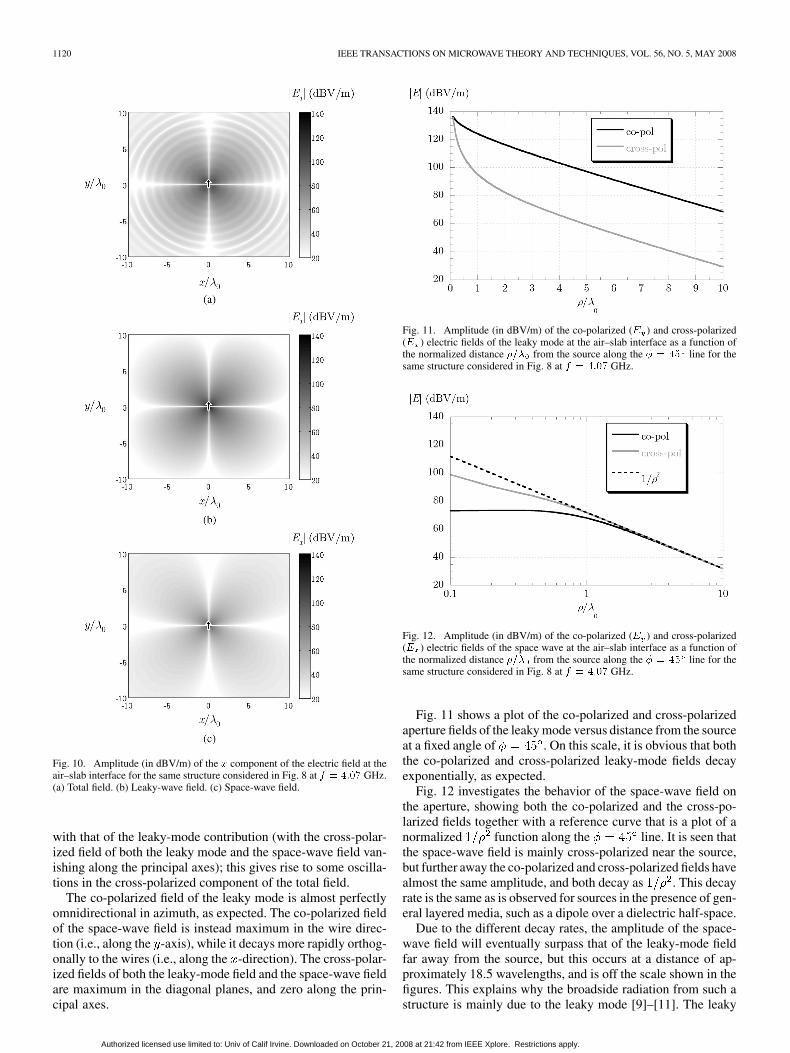
Fig. 9. Amplitude (in dBV/m) of the � component of the electric field at theair–slab interface for the same structure considered in Fig. 8 at � � ����GHz.(a) Total field. (b) Leaky-wave field. (c) Space-wave field.
low-permittivity slab that is optimized for maximum radiationat broadside (as in Fig. 8), the leaky-mode field is expected todominate the total field of the aperture. To verify this, results areshown in Figs. 9 and 10 for the leaky-mode field and the space-wave field on the aperture for the case shown in Fig. 8 for theco-polarized ( ) and cross-polarized fields ( ), respectively. Theleaky-mode field and space-wave field have been numericallyevaluated, as explained in Section II-C. The total field on theaperture is also shown, plotted on the same scale as the leaky-mode and space-wave fields for an easy comparison.
Fig. 9 verifies that the leaky-mode field is the dominant con-tributor to the co-polarized field of the aperture with the ampli-tude of the co-polarized space-wave field being on the order of50 dB lower. On the other hand, Fig. 10 shows that the space-wave contribution to the cross-polarized field on the aperture isnot negligible, its amplitude being comparable (but a bit weaker)
Authorized licensed use limited to: Univ of Calif Irvine. Downloaded on October 21, 2008 at 21:42 from IEEE Xplore. Restrictions apply.
1120 IEEE TRANSACTIONS ON MICROWAVE THEORY AND TECHNIQUES, VOL. 56, NO. 5, MAY 2008
Fig. 10. Amplitude (in dBV/m) of the � component of the electric field at theair–slab interface for the same structure considered in Fig. 8 at � � ���� GHz.(a) Total field. (b) Leaky-wave field. (c) Space-wave field.
with that of the leaky-mode contribution (with the cross-polar-ized field of both the leaky mode and the space-wave field van-ishing along the principal axes); this gives rise to some oscilla-tions in the cross-polarized component of the total field.
The co-polarized field of the leaky mode is almost perfectlyomnidirectional in azimuth, as expected. The co-polarized fieldof the space-wave field is instead maximum in the wire direc-tion (i.e., along the -axis), while it decays more rapidly orthog-onally to the wires (i.e., along the -direction). The cross-polar-ized fields of both the leaky-mode field and the space-wave fieldare maximum in the diagonal planes, and zero along the prin-cipal axes.
Fig. 11. Amplitude (in dBV/m) of the co-polarized (� ) and cross-polarized(� ) electric fields of the leaky mode at the air–slab interface as a function ofthe normalized distance ��� from the source along the � � �� line for thesame structure considered in Fig. 8 at � � ���� GHz.
Fig. 12. Amplitude (in dBV/m) of the co-polarized (� ) and cross-polarized(� ) electric fields of the space wave at the air–slab interface as a function ofthe normalized distance ��� from the source along the � � �� line for thesame structure considered in Fig. 8 at � � ���� GHz.
Fig. 11 shows a plot of the co-polarized and cross-polarizedaperture fields of the leaky mode versus distance from the sourceat a fixed angle of . On this scale, it is obvious that boththe co-polarized and cross-polarized leaky-mode fields decayexponentially, as expected.
Fig. 12 investigates the behavior of the space-wave field onthe aperture, showing both the co-polarized and the cross-po-larized fields together with a reference curve that is a plot of anormalized function along the line. It is seen thatthe space-wave field is mainly cross-polarized near the source,but further away the co-polarized and cross-polarized fields havealmost the same amplitude, and both decay as . This decayrate is the same as is observed for sources in the presence of gen-eral layered media, such as a dipole over a dielectric half-space.
Due to the different decay rates, the amplitude of the space-wave field will eventually surpass that of the leaky-mode fieldfar away from the source, but this occurs at a distance of ap-proximately 18.5 wavelengths, and is off the scale shown in thefigures. This explains why the broadside radiation from such astructure is mainly due to the leaky mode [9]–[11]. The leaky
Authorized licensed use limited to: Univ of Calif Irvine. Downloaded on October 21, 2008 at 21:42 from IEEE Xplore. Restrictions apply.
BURGHIGNOLI et al.: MODAL PROPAGATION AND EXCITATION ON WIRE-MEDIUM SLAB 1121
Fig. 13. Amplitude of the Cartesian components of the electric field at theair–slab interface of a truncated grounded wire-medium slab excited by a hori-zontal electric dipole, calculated with FEKO at � � ���� GHz. Parameters: asin Fig. 8.
mode is very dominant because the dipole source is located in-side the homogenized wire-medium (low-permittivity) slab atthe optimum location (in the middle of the slab) to best excite theleaky mode, while also minimizing the space-wave field. Otherresults (not shown) reveal that, when the dipole is located nearthe interface, the leaky mode becomes somewhat weaker and thespace-wave field becomes much stronger so that the two nowhave comparable amplitudes over the range of distances shownin Figs. 11 and 12.
As mentioned in Section II-C, the use of a homogenizedmodel for calculating the near field excited by a finite sourcemay be questionable since this model cannot take into accountthe microscopic near-field interaction of the source with thelattice (hence, it would not provide reliable results for the inputimpedance of a more realistic source). To assess the validityof the above conclusions about the features of the field at theair–slab interface, an actual wire-medium structure has thenbeen simulated with a general-purpose commercial softwaretool (FEKO) based on the MoM in the spatial domain. Atruncated slab with the same parameters as in Fig. 8 has beenconsidered with a finite extension in the -plane equal to
. In Fig. 13(a), the amplitude of the componentis reported with a grayscale map and equiamplitude contour
lines on the plane ; it can be observed that is indeedsubstantially independent of the azimuthal angle until we getfurther away. In Fig. 13(b), the component is reported; herethe microscopic structure of the near field is clearly apparent,which is not visible in the corresponding homogenized resultsin Fig. 8(b). However, it is confirmed that the componentis dominated in magnitude by the component, although thedifference between the two is only one order of magnitude inthe full-wave results.
In conclusion, when a single dominant leaky mode is excited,the aperture field at the air–slab interface is almost perfectlylinearly polarized with an omnidirectional amplitude, and thehomogenized slab model, although not able to capture the finedetails of the near field, correctly predicts such qualitative fea-tures. It is worth noting that these features are typical of planarleaky-wave antennas based on conventional designs when op-timized for broadside radiation (see, e.g., [20], where a sub-strate–superstrate configuration is analyzed); however, for con-ventional designs, these features are due to the excitation of apair of and leaky modes, whereas a single leakymode is excited in the present wire-medium configuration.
V. CONCLUSION
Modal propagation and excitation on a wire-medium slabin free space have been investigated through both a homoge-nized model of the wire medium, which takes into account bothanisotropy and spatial dispersion, and rigorous full-wave simu-lations.
The homogenized analysis has lead to the result that modalpropagation is omnidirectional, i.e., independent of the propaga-tion angle along the slab, and that surface waves cannot exist. Aparametric analysis of the dispersion features of the leaky modeshas been presented to illustrate the degree of modal omnidirec-tionality as a function of the geometrical parameters of the wiremedium and of frequency.
The excitation of a grounded wire-medium slab by means ofa horizontal electric dipole has also been studied. The main fea-tures of the field at the air–slab interface, i.e., its character ofbeing almost perfectly linearly polarized along the wire direc-tion and omnidirectional in magnitude, have been ascertainedthrough a MoM simulation of an actual truncated wire-mediumstructure, and have been shown to be correctly predicted by theapproximate homogenized model.
Future investigations will concern the input-impedance prop-erties of more realistic sources placed inside the consideredwire-medium slabs, and they will necessarily require the rig-orous treatment of the near-field interaction between the sourceand metal wires through full-wave simulations of the actual pe-riodic material.
APPENDIX
EQUIVALENT TRANSMISSION LINES FOR AND FIELDS
Here, the transverse equivalent networks in the -direction arederived for and waves inside an electrically uniaxialmedium with a spatially and temporally dispersive permittivity,as in (1), starting from the spectral form of Maxwell’s equationsand taking into account the presence of impressed electric andmagnetic currents.
Authorized licensed use limited to: Univ of Calif Irvine. Downloaded on October 21, 2008 at 21:42 from IEEE Xplore. Restrictions apply.
1122 IEEE TRANSACTIONS ON MICROWAVE THEORY AND TECHNIQUES, VOL. 56, NO. 5, MAY 2008
By Fourier transforming the Maxwell equations with respectto and , we have
(21)
(22)
In the case, and , and by simple manipu-lations of (21) and (22), it is possible to express all the remainingfield components in terms of and and of the impressedcurrents. The second equation of (21) and the first equation of(22) can then be written as transmission line equations
(23)
where
(24)
The propagation constant and characteristic impedance of theequivalent transmission line are then
(25)
Note that, by letting , from the first equa-tion of (25), it is inferred that
(26)
Hence, the normalized phase constant (i.e., the effectiveindex ) of a uniform plane wave (i.e., an ordinary wave)inside the considered medium is equal to regardless of itsdirection of propagation, as expected.
In the case, and ; reasoning as in thecase, the first equation of (21), and the second equation
of (22) can then be written as transmission line equations, as in(23), but with a superscript where
(27)
The propagation constant and characteristic impedance of theequivalent transmission line are then
(28)
Again, by letting , one obtains from thefirst equation of (28) and (1)
(29)From (29), it is concluded that the normalized phase constant
(i.e., the effective index ) of a uniform plane wave(i.e., an extraordinary wave) inside the considered medium is
equal to , regardless of its direction of propaga-tion. The fact that is independent of the direction of propaga-tion is a consequence of the spatially dispersive model adoptedfor the effective medium and expressed by (1), as observed in[3].
REFERENCES
[1] J. Brown, “Artificial dielectrics having refractive indexes less thanunity,” Proc. Inst. Elect. Eng., vol. 100, pp. 51–62, May 1953.
[2] G. Shvets, “Photonic approach to making a surface wave accelerator,”in Proc. 10th Adv. Accelerator Concepts Workshop, 2002, vol. CP647,pp. 371–382.
[3] P. A. Belov, R. Marqués, S. I. Maslovski, I. S. Nefedov, M. Silveir-inha, C. R. Simovski, and S. A. Tretyakov, “Strong spatial dispersionin wire media in the very large wavelength limit,” Phys. Rev. B, Con-dens. Matter, vol. 67, pp. 113103-1–113103-4, 2003.
[4] C. R. Simovski and P. A. Belov, “Low-frequency spatial dispersionin wire media,” Phys. Rev. E, Stat. Phys. Plasmas Fluids Relat. Inter-discip. Top., vol. 70, pp. 046616-1–046616-8, Oct. 2004.
[5] M. G. Silveirinha and C. A. Fernandes, “Homogenization of 3-D-con-nected and nonconnected wire metamaterial,” IEEE Trans. Microw.Theory Tech., vol. 53, no. 4, pp. 1418–1430, Apr. 2005.
[6] M. G. Silveirinha, “Additional boundary condition for the wiremedium,” IEEE Trans. Antennas Propag., vol. 54, no. 6, pp.1766–1780, Jun. 2006.
[7] I. S. Nefedov, A. J. Viitanen, and S. A. Tretyakov, “Propagating andevanescent modes in two-dimensional wire media,” Phys. Rev. E, Stat.Phys. Plasmas Fluids Relat. Interdiscip. Top., vol. 71, pp. 046612-1–046612-10, 2005.
Authorized licensed use limited to: Univ of Calif Irvine. Downloaded on October 21, 2008 at 21:42 from IEEE Xplore. Restrictions apply.
BURGHIGNOLI et al.: MODAL PROPAGATION AND EXCITATION ON WIRE-MEDIUM SLAB 1123
[8] I. S. Nefedov and A. J. Viitanen, “Guided waves in uniaxial wiremedium slab,” PIER, vol. 51, pp. 167–185, 2003.
[9] P. Burghignoli, G. Lovat, F. Capolino, D. R. Jackson, and D. R. Wilton,“3D directive radiation from a horizontal dipole embedded in a homog-enized grounded wire-medium slab,” in IEEE AP-S Conf. Dig., Albu-querque, NM, Jul. 9–14, 2006, pp. 2989–2992.
[10] P. Burghignoli, G. Lovat, F. Capolino, D. R. Jackson, and D. R. Wilton,“Leaky modes on a grounded wire-medium slab,” in IEEE MTT-S Int.Microw. Symp. Dig., Honolulu, HI, Jun. 3–8, 2007, pp. 1663–1666.
[11] P. Burghignoli, G. Lovat, F. Capolino, D. R. Jackson, and D. R. Wilton,“Directive leaky-wave radiation from a dipole source in a wire-mediumslab,” IEEE Trans. Antennas Propag., vol. 56, no. 5, May 2008, to bepublished.
[12] P. A. Belov, S. A. Tretyakov, and A. J. Viitanen, “Dispersion and re-flection properties of artificial media formed by regular lattices of ide-ally conducting wires,” J. Electromagn. Waves Applicat., vol. 16, pp.1153–1170, Sep. 2002.
[13] G. Guida, D. Maystre, G. Tayeb, and P. Vincent, “Mean-field theoryof two-dimensional metallic photonic crystals,” J. Opt. Soc. Amer. B,Opt. Phys., vol. 15, pp. 2308–2315, 1998.
[14] P. Baccarelli, P. Burghignoli, F. Frezza, A. Galli, P. Lampariello, G.Lovat, and S. Paulotto, “Fundamental modal properties of surfacewaves on metamaterial grounded slabs,” IEEE Trans. Microw. TheoryTech., vol. 53, no. 4, pp. 1431–1442, Apr. 2005.
[15] F. Capolino, D. R. Jackson, D. R. Wilton, and L. B. Felsen, “Compar-ison of methods for calculating the field excited by a dipole near a 2-Dperiodic material,” IEEE Trans. Antennas Propag., vol. 55, no. 6, pp.1644–1655, Jun. 2007.
[16] F. Capolino, D. R. Wilton, and W. A. Johnson, “Efficient calculation ofthe 2-D Green’s function for 1-D periodic structures using the Ewaldmethod,” IEEE Trans. Antennas Propag., vol. 53, no. 9, pp. 2977–2984,Sep. 2005.
[17] W. Chew, Waves and Fields in Inhomogeneous Media. Piscataway,NJ: IEEE Press, 1995.
[18] A. Hessel, “Travelling-wave antennas,” in Antenna Theory, R. E. Collinand F. J. Zucker, Eds. New York: McGraw-Hill, 1969, ch. 19, pt. 2.
[19] G. Lovat, P. Burghignoli, F. Capolino, D. R. Jackson, and D. R. Wilton,“Analysis of directive radiation from a line source in a metamaterialslab with low permittivity,” IEEE Trans. Antennas Propag., vol. 54,no. 3, pp. 1017–1030, Mar. 2006.
[20] A. Polemi and S. Maci, “On the polarization properties of a dielectricleaky wave antenna,” IEEE Antennas Wireless Propag. Lett., vol. 5, no.1, pp. 306–310, Dec. 2006.
Paolo Burghignoli (S’97–M’01–SM’08) was bornin Rome, Italy, on February 18, 1973. He received theLaurea degree (cum laude) in electronic engineeringand Ph.D. degree in applied electromagnetics from“La Sapienza” University of Rome, Rome, Italy, in1997 and 2001, respectively.
In 1997, he joined the Electronic Engineering De-partment, “La Sapienza” University of Rome, wherehe is currently an Associate Researcher. From Jan-uary 2004 to July 2004, he was a Visiting ResearchAssistant Professor with the University of Houston,
Houston, TX. His scientific interests include analysis and design of planar leaky-wave antennas, numerical methods for the analysis of passive guiding and radi-ating microwave structures, periodic structures, and propagation and radiationin metamaterials.
Dr. Burghignoli was the recipient of a 2003 IEEE Microwave Theory andTechniques Society (IEEE MTT-S) Graduate Fellowship, the 2005 Raj MittraTravel Grant for Junior Researchers presented at the IEEE Antennas and Prop-agation Society Symposium, Washington, DC, and the 2007 “Giorgio Barzilai”Laurea Prize presented by the former IEEE Central & South Italy Section.
Giampiero Lovat (S’02–M’06) was born in Rome,Italy, on May 31, 1975. He received the Laureadegree (cum laude) in electronic engineering andPh.D. degree in applied electromagnetics from “LaSapienza” University of Rome, Rome, Italy, in 2001and 2004, respectively.
In 2005, he joined the Electrical EngineeringDepartment, “La Sapienza” University of Rome,where he is currently an Associate Researcher.From January 2004 to July 2004, he was a VisitingScholar with the University of Houston, Houston,
TX. He coauthored a book on electromagnetic shielding. His current researchinterests include leaky-wave antennas, periodic structures, complex media, andelectromagnetic shielding.
Dr. Lovat was the recipient of the 2005 Young Scientist Award presented atthe URSI General Assembly, New Delhi, India.
Filippo Capolino (S’94–M’97–SM’04) was bornin Florence, Italy, in 1967. He received the Laureadegree (cum laude) in electronic engineering andPh.D. degree from the University of Florence,Florence, Italy, in 1993 and 1997, respectively.
He is currently an Assistant Professor with theDepartment of Information Engineering, Universityof Siena, Siena, Italy. From 1997 to 1998, he wasa Fulbright Research Visitor with the Departmentof Aerospace and Mechanical Engineering, BostonUniversity, Boston, MA, where he continued his
research under a grant from the Italian National Council for Research (CNR)from 1998 to 1999. From 2000 to 2001, he was a Research Assistant VisitingProfessor with the Department of Electrical and Computer Engineering, Uni-versity of Houston, Houston, TX, where he is currently an Adjunct AssistantProfessor. From November to December 2003, he was an Invited AssistantProfessor with the Institut Fresnel, Marseille, France. He is an AssociateEditor for the new Elsevier journal Metamaterials. His research interestsinclude theoretical and applied electromagnetics focused on high-frequencyshort-pulse radiation, array antennas, periodic structures, numerical modeling,and metamaterials.
Dr. Capolino is the Coordinator of the Metamorphose EU DoctoralProgrammes on Metamaterials. He is an associate editor for the IEEETRANSACTIONS ON ANTENNAS AND PROPAGATION. He was the recipient ofthe 1994 MMET’94 Student Paper Competition Award, the 1996 and 2006Raj Mittra Travel Grant for Young Scientists, the 1996 “Barzilai” Prize forthe best paper presented at the National Italian Congress of Electromagnetism(XI RiNEm), and a 1998 Young Scientist Award for participating in the URSIInternational Symposium on Electromagnetic Theory. He was also the recipientof the R. W. P. King Prize Paper Award presented by the IEEE Antennas andPropagation Society for the Best Paper of 2000 by an author under the age of36.
David R. Jackson (S’83–M’84–SM’95–F’99) wasborn in St. Louis, MO, on March 28, 1957. He re-ceived the B.S.E.E. and M.S.E.E. degrees from theUniversity of Missouri, Columbia, in 1979 and 1981,respectively, and the Ph.D. degree in electrical engi-neering from the University of California at Los An-geles (UCLA), in 1985.
From 1985 to 1991, he was an Assistant Professorwith the Department of Electrical and ComputerEngineering, University of Houston, Houston, TX.From 1991 to 1998 he was an Associate Professor,
and since 1998, he has been a Professor with this same department. He hasalso served as an Associate Editor for the Journal of Radio Science and theInternational Journal of RF and Microwave Computer-Aided Engineering. Hiscurrent research interests include microstrip antennas and circuits, leaky-waveantennas, leakage and radiation effects in microwave integrated circuits,periodic structures, and electromagnetic compatibility (EMC).
Dr. Jackson is currently the chair of the Transnational Committee of the IEEEAntennas and Propagation Society (IEEE AP-S), and chair for URSI, U.S. Com-mission B. He is also on the Editorial Board of the IEEE TRANSACTIONS ON
MICROWAVE THEORY AND TECHNIQUES. He was Chapter activities coordinatorfor the IEEE AP-S, a Distinguished Lecturer for the IEEE AP-S, an associateeditor for the IEEE TRANSACTIONS ON ANTENNAS AND PROPAGATION, and amember of the IEEE AP-S Administrative Committee (AdCom).
Authorized licensed use limited to: Univ of Calif Irvine. Downloaded on October 21, 2008 at 21:42 from IEEE Xplore. Restrictions apply.
1124 IEEE TRANSACTIONS ON MICROWAVE THEORY AND TECHNIQUES, VOL. 56, NO. 5, MAY 2008
Donald R. Wilton (S’63–M’65–SM’80–F’87–LF’08) was born in Lawton, OK, on October 25,1942. He received the B.S., M.S., and Ph.D. degreesfrom the University of Illinois at Urbana-Cham-paign, in 1964, 1966, and 1970, respectively.
From 1965 to 1968, he was with the HughesAircraft Company, Fullerton, CA, where he wasengaged in the analysis and design of phased-arrayantennas. From 1970 to 1983, he was with theDepartment of Electrical Engineering, University ofMississippi. Since 1983, he has been Professor of
electrical engineering with the University of Houston, Houston, TX. From 1978
to 1979, he was a Visiting Professor with Syracuse University. From 2004 to2005, he was a Visiting Scholar with the Polytechnic of Turin, Sandia NationalLaboratories, and the University of Washington. He has authored or coauthoredmany publications, lectured, and consulted extensively. His primary researchinterest is in computational electromagnetics.
Dr. Wilton has served as an associate editor for the IEEE TRANSACTIONS
ON ANTENNAS AND PROPAGATION. He has also served the IEEE Antennas andPropagation Society (IEEE AP-S) as a Distinguished National Lecturer and asa member of their Administrative Committee (AdCom). He is also a member ofCommission B, URSI, in which he has held various offices including chair ofU.S. Commission B. He was the recipient of the IEEE Third Millennium Medal.
Authorized licensed use limited to: Univ of Calif Irvine. Downloaded on October 21, 2008 at 21:42 from IEEE Xplore. Restrictions apply.


![Elementary Survey Arthur Higgins Lovat 1947 [PDF Library]](https://static.documents.pub/doc/80x56/550283174a7959362a8b49be/elementary-survey-arthur-higgins-lovat-1947-pdf-library.jpg)


