1.13.0 Prestressed Concrete Concrete in which internal stresses (forces) are induced by means of prestressing steel tendons such that tensile stresses resulting from loads are counteracted to a desired degree is called prestressed concrete. There are two basic methods of prestressing concrete—pretensioning and posttensioning. Pretensioned Concrete In this process, which generally occurs in a factory environment, stressing strands are placed in ten- sion in a concrete form prior to the placement of concrete in that form. After the concrete has cured to a specific strength, the steel stressing strands are “unloaded” so that the stresses are transferred to the concrete by the bond between the steel strands and the concrete. This process is most fre- quently used in the production of hollow core or solid precast plank. 1.13.1 Posttensioned Concrete Posttensioned concrete is a field operation and, therefore, knowledgeable and experienced person- nel are required in order to produce a structurally sound product in a safe environment. Posttensioning is a method to produce structural concrete slabs, girders, and beams utilizing pre- stressing steel as part of a component referred to as a “tendon” which imparts prestressing forces to the concrete component. The tendons can be either encapsulated in flexible metal or plastic sheath- ing, or unbonded and pregreased, or mastic coated. These tendons are individual wires as opposed to the stranded wires used in the prestressing process. Most tendons are shipped in bundles that are tied or banded and safety concerns begin even before any tendons are placed in the form. When the securing bands of the tendons are cut, the bun- dle becomes an uncoiled spring and care must be taken to avoid injury to those unloading the ten- dons prior to installation. The banded tendons are usually bundled to form strand groups and not more than five 1 / 2 inch (12.7 mm) diameter tendons and not more than four 0.6 inch (15.2 mm) diameter strand tendons should be banded in one group. When banding tendons together, care must be taken to avoid damaging the plastic sheathing. The tendons are smoothly splayed out at the anchorage as illustrated in Fig. 1.13.2. The design en- gineer will usually specify the procedures for installing tendons around small openings in a slab (Fig. 1.13.3). It is possible to splice tendons that may be too short by using tendon couplers (Fig. 1.13.4). Dead end anchorages are generally attached at the posttensioning supplier’s plant. A typical jack- ing device is shown in Figure 1.13.5. Concrete 45 1.13.2 Typical Tendon Layout
Transcript
1.13.0 Prestressed Concrete
Concrete in which internal stresses (forces) are induced by means of prestressing steel tendons suchthat tensile stresses resulting from loads are counteracted to a desired degree is called prestressedconcrete. There are two basic methods of prestressing concrete—pretensioning and posttensioning.
Pretensioned Concrete
In this process, which generally occurs in a factory environment, stressing strands are placed in ten-sion in a concrete form prior to the placement of concrete in that form. After the concrete has curedto a specific strength, the steel stressing strands are “unloaded” so that the stresses are transferredto the concrete by the bond between the steel strands and the concrete. This process is most fre-quently used in the production of hollow core or solid precast plank.
1.13.1 Posttensioned Concrete
Posttensioned concrete is a field operation and, therefore, knowledgeable and experienced person-nel are required in order to produce a structurally sound product in a safe environment.
Posttensioning is a method to produce structural concrete slabs, girders, and beams utilizing pre-stressing steel as part of a component referred to as a “tendon” which imparts prestressing forces tothe concrete component. The tendons can be either encapsulated in flexible metal or plastic sheath-ing, or unbonded and pregreased, or mastic coated.
These tendons are individual wires as opposed to the stranded wires used in the prestressingprocess. Most tendons are shipped in bundles that are tied or banded and safety concerns begin evenbefore any tendons are placed in the form. When the securing bands of the tendons are cut, the bun-dle becomes an uncoiled spring and care must be taken to avoid injury to those unloading the ten-dons prior to installation.
The banded tendons are usually bundled to form strand groups and not more than five 1⁄2 inch (12.7mm) diameter tendons and not more than four 0.6 inch (15.2 mm) diameter strand tendons shouldbe banded in one group.
When banding tendons together, care must be taken to avoid damaging the plastic sheathing.The tendons are smoothly splayed out at the anchorage as illustrated in Fig. 1.13.2. The design en-
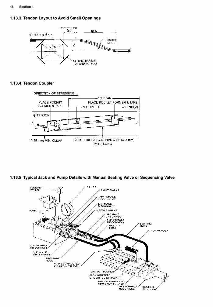
gineer will usually specify the procedures for installing tendons around small openings in a slab (Fig.1.13.3). It is possible to splice tendons that may be too short by using tendon couplers (Fig. 1.13.4).
Dead end anchorages are generally attached at the posttensioning supplier’s plant. A typical jack-ing device is shown in Figure 1.13.5.
Concrete 45
1.13.2 Typical Tendon Layout
46 Section 1
1.13.3 Tendon Layout to Avoid Small Openings
1.13.4 Tendon Coupler
1.13.5 Typical Jack and Pump Details with Manual Seating Valve or Sequencing Valve
1.13.6 Some Posttensioning Do’s and Don’ts
During concrete placement:
1. Any chloride bearing chemicals in the concrete must be avoided for obvious reasons.
2. Concrete should not be placed until all tendons and reinforcing steel have been inspected and arein compliance with the design criteria and approved shop drawings.
3. During the placement of concrete, care must be taken to avoid moving the tendons out of theirdesignated positions.
4. When truck dumping, do not place too much concrete in one location to avoid excessive spread-ing which may effect the placement of the tendons.
5. When pumping concrete do not rest the hose on the tendons, and move the hose nozzle in such amanner so as to avoid displacement of the tendons.
6. When placing concrete by crane and bucket, release the concrete at an elevation that avoids dis-placement of the tendons.
7. Do not place the vibrator on the tendons; avoid contact between the vibrator and the concrete asmuch as possible.
Tendon Stressing
1. Do not begin tendon stressing until break tests of concrete cylinders indicate that the concretehas attained the minimum compressive strength as specified by the design engineer.
2. Edge forms should be removed as quickly as possible to make it easier to clean out the anchor cav-ity while the concrete is still “green.”
3. Check the integrity of the concrete, both inside the pocket and on all exposed surfaces. If thereis evidence of honeycomb in the concrete, or there are voids or cracks or other signs that the con-crete is substandard, DO NOT STRESS IT. One way of determining the existence of honeycomb-ing is to tap the suspected area with a hammer. If a hollow sound is detected, notify the structuralengineer for further instructions.
4. Check the tendon to ensure that it is perpendicular to the anchor and the anchor is parallel to theface of the concrete, unless design dictates otherwise.
5. Remove any excess corrosion inhibiting coatings, any dirt, sand, or concrete slurry from the ten-don tails.
6. Inspect the wedges to ensure that they have been installed evenly and have been seated properly.
7. Each jack should have its own 30-amp protected circuit and all electrical circuits must begrounded.
8. Check all hose connections and make sure that a pressure gauge is installed and functioning.
9. The pump and jack should be started and checked in both extended and retracted positions. Arethey any hydraulic leaks? Is the seating plunger functioning properly?
Stressing the Tendons
1. Although stressing should not commence until the proper design strength of the concrete hasbeen achieved, it is advisable to begin stressing as soon as design strength is verified.
2. A safe, clear area must be created for the stressing crew.
3. Qualified inspection personnel must be present to measure elongations and if any variations be-tween calculated and actual elongations consistently exceed tolerance, stressing should cease andnot start up again until the cause has been determined.
4. When stressing above grade, jacks and pumps need to be secured to a fixed object to preventequipment from being thrown off the elevated platform should a tendon fail during stressing.
5. The pump should be operated by a pendant switch, which will allow the operator to stand awayfrom the pump should a tendon or jack gripper fail.
Concrete 47
The Don’ts of Stressing
1. Don’t stress any tendons that contain concrete slurry inside the anchor cavity. The slurry willprevent proper seating of the wedges.
2. Don’t use the jack when it does not seat properly on the face of the anchor.
3. Don’t overstress tendons to achieve proper elongation.
4. Don’t allow obstructions in the path of the jack extension.
5. Don’t use extension cords longer than 100 feet (30 meters). All extension cords must be threewire, 12 gauge, minimum.
6. Don’t continue stressing if it appears that something is not working properly.
7. Don’t detension with loose plates, spacing shims, or piggy backing.
8. Don’t stand close to the jack or between the jack and the pump while in operation.
9. Don’t permit workers to stand in the immediate area of the jack.
10. If unsure of any operation or procedure—STOP and get professional instructions.
1.13.7 Glossary of Terms
Anchorage A device used to anchor the tendon to the concrete member. In pretensioning, this de-vice is used to anchor the tendon during hardening of the concrete.
Bonded tendons Tendons that are bonded to the concrete by grouting or other means and aretherefore not free to move relative to the concrete.
Initial prestress The stress (force) in the tension immediately after transferring the prestressingforce to the concrete. This occurs after the wedges (pieces of tapered metal with teeth that biteinto the prestressing steel during transfer of the prestressing force) have been seated in the an-chor.
Prestress To place a material (e.g., concrete) in a state of compression prior to the application ofloads.
Prestressing steel High strength steel used in the process, most frequently made up of seven wirestrands or single wires, bars, or groups of wires or bars.
Posttensioning A method of prestressing in which the tendons are tensioned after the concretehas hardened.
Sheath An enclosure in which the prestressing steel is placed to prevent bonding during concreteplacement and also to protect the tendons from corrosion if the tendons are to remain unbonded.
Tendon The complete assembly that consists of the prestressing steel, sheathing, and associatedanchorages.
Unbonded tendons Tendons in which the prestressing steel is permanently free to move relativeto the concrete to which they are applying their prestressing forces.
The Posttensioning Institute (PCI) in Phoenix, Arizona, has developed guidelines for field person-nel involved in installation, stressing, and finishing of unbonded single-strand tendons. Their guide-lines represent generally accepted industry practices, but each posttensioned concrete installationmay vary according to specific engineering demands.
1.14.0 Precast Concrete
Precast concrete can be produced at the job site, which is the case in tilt-up construction or it canbe factory produced in an indoor, controlled environment where it is often autoclaved, a process in-volving high-pressure steam to accelerate early strength. The design of connections of the variouscomponents of a precast concrete structural system is of utmost importance in order to assure thatloads are transferred from one member to another and overall system stability is achieved.
A well-designed connection also takes into account practicality in both manufacture and installa-tion. The designer must always consider cost-effectiveness since contractors are most likely to com-pare a precast system to other structural designs during the project’s genesis and design development.
48 Section 1
Architectural precast panels often prove cost-effective and allow a designer considerable latitudein surface treatment and overall design.
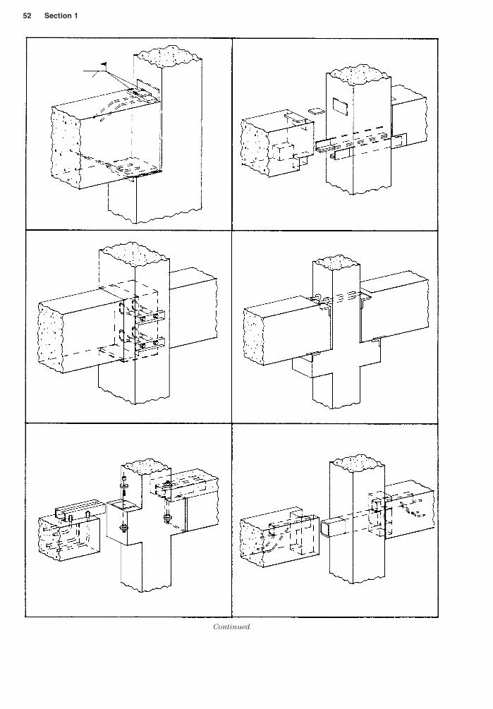
Typical beam-to-column connections, precast-to-steel frame connections, precast plank, column–to–cast-in-place and other connections are shown in the following detail drawings, which are to beconsidered guidelines only and are not meant to be replicated as part of any precast concrete system.
Concrete 49
(By permission from the Prestressed Concrete Institute (PCI), Chicago, Illinois.)
1.14.1 Precast Welded Tieback Connections
50 Section 1
Continued
Concrete 51
(By permission from the Prestressed Concrete Institute (PCI), Chicago, Illinois.)
1.14.2 Precast—Column-to-Beam Connections
52 Section 1
Continued
Concrete 53
Continued
54 Section 1
(By permission from the Prestressed Concrete Institute (PCI), Chicago, Illinois.)
(By permission from the Prestressed Concrete Institute (PCI), Chicago, Illinois.)
1.14.3.1 Precast—Plank-to-CMU Wall Connections
Concrete 57
(By permission from the Prestressed Concrete Institute (PCI), Chicago, Illinois.)
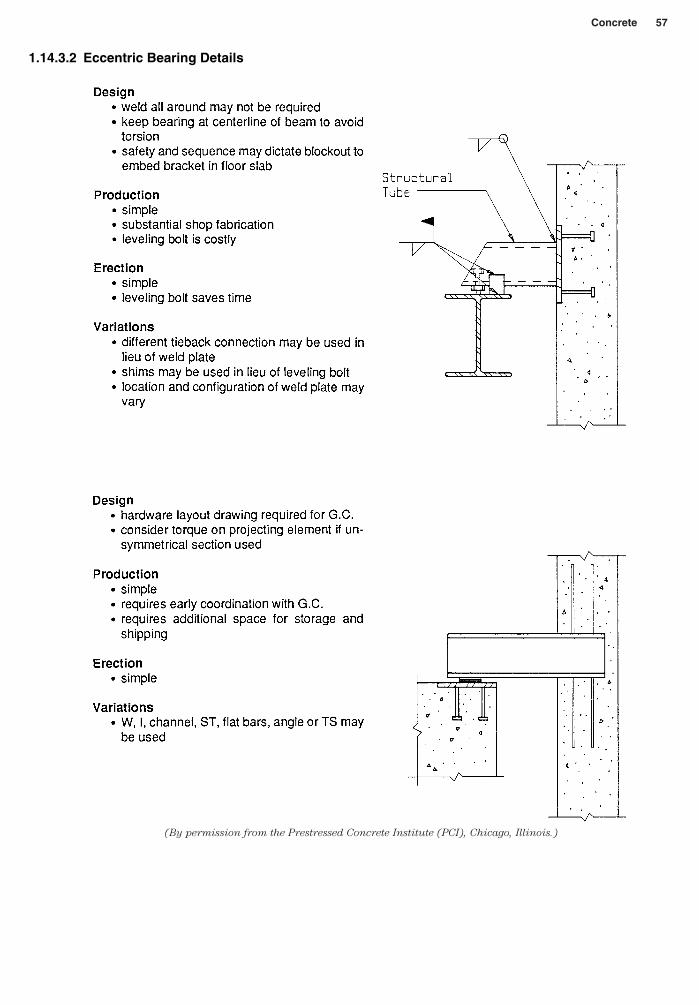
1.14.3.2 Eccentric Bearing Details
58 Section 1
(By permission from the Prestressed Concrete Institute (PCI), Chicago, Illinois.)
1.14.3.3 Beam-to-Wall Connections
Concrete 59
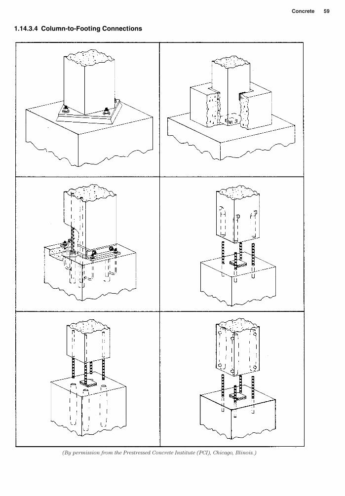
(By permission from the Prestressed Concrete Institute (PCI), Chicago, Illinois.)
1.14.3.4 Column-to-Footing Connections
60 Section 1
Continued
Concrete 61
(By permission from the Prestressed Concrete Institute (PCI), Chicago, Illinois.)
1.14.3.5 Tie Forces and Typical Tie Arrangements
62 Section 1
(By permission from the Prestressed Concrete Institute (PCI), Chicago, Illinois.)
1.14.3.6 Hanger Connections
Concrete 63
(By permission from the Prestressed Concrete Institute (PCI), Chicago, Illinois.)
1.14.3.7 Column Base Connections
64 Section 1
(By permission from the Prestressed Concrete Institute (PCI), Chicago, Illinois.)
(By permission from the Prestressed Concrete Institute (PCI), Chicago, Illinois.)
1.14.3.8 Corbel Design
1.14.3.9 Corbel Force Diagrams and Typical Reinforcement
Concrete 65
(By permission from the Prestressed Concrete Institute
(PCI), Chicago, Illinois.)
1.14.3.10 Keyed Joint Connections
66 Section 1
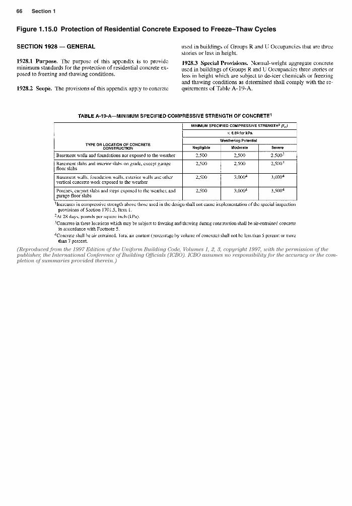
(Reproduced from the 1997 Edition of the Uniform Building Code, Volumes 1, 2, 3, copyright 1997, with the permission of the
publisher, the International Conference of Building Officials (ICBO). ICBO assumes no responsibility for the accuracy or the com-
pletion of summaries provided therein.)
Figure 1.15.0 Protection of Residential Concrete Exposed to Freeze–Thaw Cycles
Concrete 67
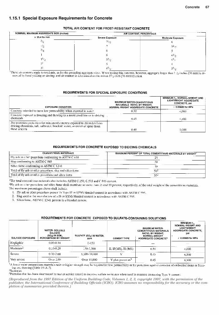
(Reproduced from the 1997 Edition of the Uniform Building Code, Volumes 1, 2, 3, copyright 1997, with the permission of the
publisher, the International Conference of Building Officials (ICBO). ICBO assumes no responsibility for the accuracy or the com-
pletion of summaries provided therein.)
1.15.1 Special Exposure Requirements for Concrete
68 Section 1
(Reproduced from the 1997 Edition of the Uniform Building Code, Volumes 1, 2, 3, copyright 1997, with the permission
of the publisher, the International Conference of Building Officials (ICBO). ICBO assumes no responsibility for the accu-
racy or the completion of summaries provided therein.)
1.16.0 Weathering Regions and Weathering Index
Concrete 69
(Reproduced from the 1997 Edition of the Uniform Building Code, Volumes 1, 2, 3, copyright 1997, with the permission of the
publisher, the International Conference of Building Officials (ICBO). ICBO assumes no responsibility for the accuracy or the com-
pletion of summaries provided therein.)
1.17.0 Seismic Map of the United States
70 Section 1
(Reproduced from the 1997 Edition of the Uni-
form Building Code, Volumes 1, 2, 3, copyright
1997, with the permission of the publisher, the In-
ternational Conference of Building Officials
(ICBO). ICBO assumes no responsibility for the
accuracy or the completion of summaries pro-
vided therein.)
Cast-in-place concrete (nonprestressed). The following min-imum concrete cover shall be provided for reinforcement:
Precast concrete (Manufactured under plant control con-ditions). The following minimum concrete cover shall be pro-vided for reinforcement:
(Reproduced from the 1997 Edition of the Uni-
form Building Code, Volumes 1, 2, 3, copyright
1997, with the permission of the publisher, the In-
ternational Conference of Building Officials
(ICBO). ICBO assumes no responsibility for the
accuracy or the completion of summaries pro-
vided therein.)
1.18.0 Minimum Cover for Reinforcement in Cast-in-Place Concrete
1.18.1 Minimum Cover for Reinforcement in Precast Concrete
Concrete 71
(Reproduced from the 1997 Edition of the Uni-
form Building Code, Volumes 1, 2, 3, copyright
1997, with the permission of the publisher, the
International Conference of Building Officials
(ICBO). ICBO assumes no responsibility for
the accuracy or the completion of summaries
provided therein.)
Prestressed concrete.
The following minimum concrete cover shall be provided for prestredded and nonprestressed reinforcement, ducts and end fittings, except as provided in Sections 1907.7.3.2 and 1907.7.3.3.
1.18.2 Minimum Cover for Reinforcement in Prestressed Concrete
72 Section 1
1.19.0 Concrete—Quality Control Checklist
Concrete 73
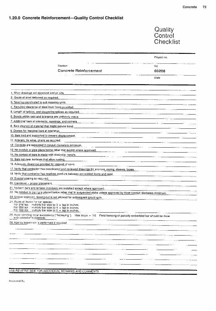
1.20.0 Concrete Reinforcement—Quality Control Checklist
74 Section 1
1.21.0 Concrete Form Removal—Quality Control Checklist


![YAMAHA ROBOT CONTROLLER SUPPORTING ......YAMAHA ROBOT CONTROLLER SUPPORTING SOFTWARE E64-P-Ver. 1.13.0 POPCOM Contents: [1] Installation Guide [2] Backup current data from robot controller](https://static.documents.pub/doc/80x56/5f0b5fca7e708231d4303425/yamaha-robot-controller-supporting-yamaha-robot-controller-supporting-software.jpg)


