O il A cid & M oisture Purge Unit The OAM-Purger May be used with Centrifugal Chillers utilizing the following refrigerants: R-11, R-113, R-114 & R-123 R-12, R-22, R-134a This manual may be use with The following OAM Purger Models: OAM-LPC200-11/113 OAM-LPC200-123 OAM-HPC200 OAM Purger Installation, Operation & Maintenance Manual Redi Controls, Inc. Literature File No. 1140-02.5 Patent 6,952,938 B2
YOU ARE URGED TO READ THIS MANUAL COMPLETELY BEFORE INSTALLING AND/OR OPERATING THIS UNIT
Upon Receiving Your Unit Inspect the unit for possible damage caused during shipping. Contact Equipment servicing before attempting to use a damaged unit. WARNINGS and Cautions
NOTE: WARNINGS and Cautions appear in highlighted boxes as illustrated below at appropriate points throughout this manual. Give special attention to these items.
WARNINGS: Provided to alert you to special situations that could result in serious personal injury, damage to your equipment, or cause your equipment not to work properly. Warnings may appear in this manual or on the equipment. Heed all Warnings.
Cautions: Designed to alert you to situations that may result in damage to your equipment. Personal safety and the proper operation of your equipment require strict observance of these precautions.
EQUIPMENT SHOULD BE INSTALLED AND OPERATED ONLY BY QUALIFIED PERSONNEL
WARNING: Certain servicing procedures may expose you to harmful materials and dangerous conditions. To minimize the possibility of injury, follow safety procedures and instructions described in this manual, on product labels and provided in material safety data sheets.
NOTE: The manufacturer has a continuous equipment improvement policy and reserves the right to change specifications and design of its products without notice.
4
T a b l e of C o n t e n t s
GENERAL INFORMATION........................................................................................................3 Upon Receiving Your Unit ................................ ................................ ................................ ................................ ......... 3 WARNINGS and Cautions ......................................................................................................................................... 3
Before You Start ................................ ................................ ................................ ................................ ........................... 7 OAM Purger Specifications ........................................................................................................................................ 7 Contents of the OAM Purger Installation Kit................................ ................................ ................................ .............. 8 Field-Provided Items .................................................................................................................................................. 8 Preliminary Inspection................................................................................................................................................ 8
OAM PURGER OPERATIONAL OVERVIEW......................................................................................................... 9 How It Works ............................................................................................................................................................. 9
The Three Operational Phases: .............................................................................................................................. 9 How the OAM Purger transfers oil to the Chiller’s oil sump................................ ................................ ..................... 10 Operating Parameters ............................................................................................................................................... 10 Operational LED Indicators...................................................................................................................................... 11 Diagnostic LED indicators........................................................................................................................................ 12 Fault LED indicators ................................................................................................................................................ 12
INSTALLING THE OAM PURGER......................................................................................................................... 13 Location and Mounting ............................................................................................................................................ 13
Figure 1. – OAM Purger Hook-up .......................................................................................................................... 14 Plumbing the OAM Purger ....................................................................................................................................... 14 Liquid Refrigerant Fill Line (with Strainer) .............................................................................................................. 15 Vapor Return Line.................................................................................................................................................... 16 Oil Return Line and Oil Filter-Dryer installation ...................................................................................................... 16
Electrical Connection.................................................................................................................................................. 23 Power Requirement .................................................................................................................................................. 23 Optional “Chiller Run” Signal................................ ................................ ................................ ................................ .. 23 Connecting Power to Purger ..................................................................................................................................... 24
Figure 4. – Electrical Control Box Field Wiring ...................................................................................................... 24
Safety Features ................................ ................................ ................................ ................................ ............................ 29 Safety # 1 guarding against over pressurization. ................................................................................................... 29 Safety # 2 guarding against over pressurization. ................................................................................................... 29 Safety guarding against inadvertent closing of any Isolation Valve(s). .................................................................. 29 Safety preventing transfer of un-distilled refrigerant into Chiller’s oil sump. ........................................................ 29 Safety guarding against Fill Solenoid (SOL-1) failing in the open, or closed position. .......................................... 30 Safety guarding against Equalization Solenoid (SOL-2) failing in the open, or closed position. ............................ 30 Safety guarding against the oil transfer Solenoid (SOL-3) failing in the open position.......................................... 30 Safety guarding Against Temperature Sensor (TS-1) failing. ................................................................................ 30 Safety guarding against Solid State Logic Board Relays sticking or not making.................................................... 30 Safety guarding against the heater failing in, ON position, or OFF position.......................................................... 30
Electrical Control Box................................................................................................................................................. 31 Terminal Block (TB-1) ............................................................................................................................................. 31 Temperature Sensor (TS-1)....................................................................................................................................... 31 250 PSIG Pressure Cut Out ....................................................................................................................................... 31 Switch (HPC-1) ........................................................................................................................................................ 31
Figure 5. – Major Components Electrical Box ......................................................................................................... 31
Temperature Sensor TS-1................................................................................................................................ 38
LEAK TESTING PROCEDURES ............................................................................................................................. 39 Leak Testing OAM Purger when installed on Chillers using LOW PRESSURE REFRIGERANTS. ..................... 39 (See page 40 for leak test procedure on chillers using High pressure refrigerants.) ............................................... 39 Leak Testing OAM Purger when installed on Chillers using HIGH PRESSURE REFRIGERANTS. .................... 40 (See page 39 for leak test procedure on chillers using Low pressure refrigerants.) ................................................ 40
PROCEDURE TO CLEAR OIL LOGGED DISTILLATION TANK...................................................................... 48 Should oil logging occur, clear the Distillation Tank using the following procedure: ....................................... 48
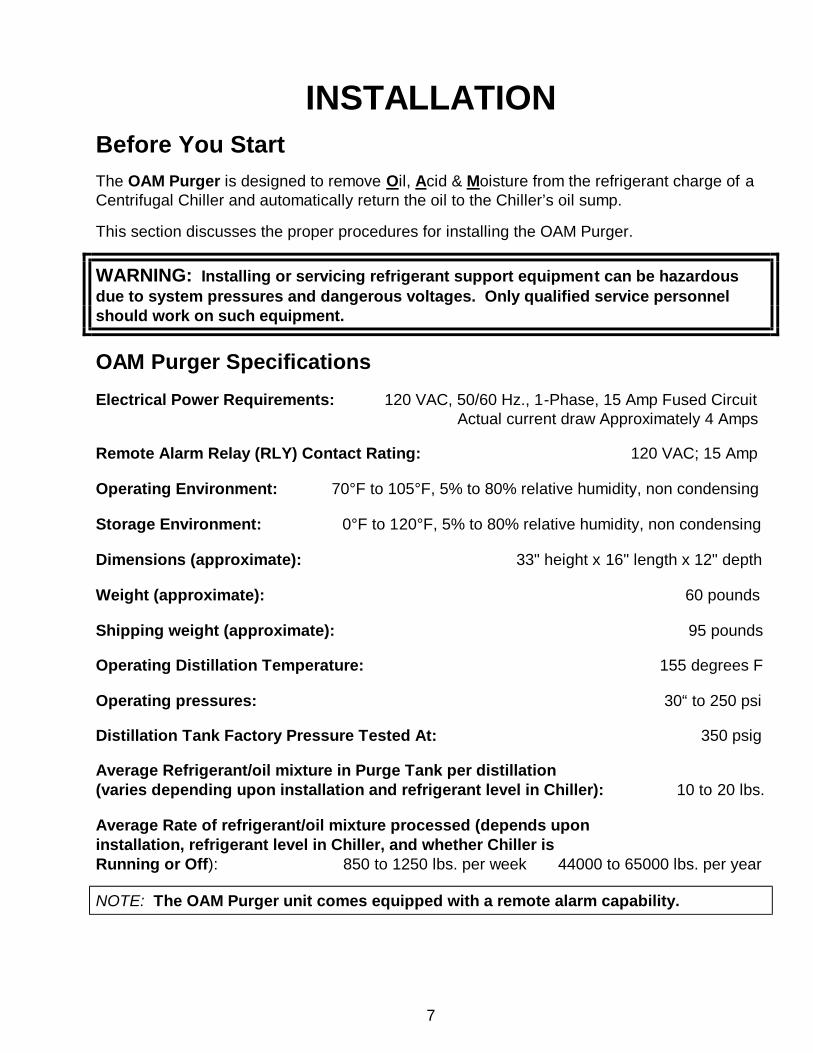
The OAM Purger is designed to remove Oil, Acid & Moisture from the refrigerant charge of a Centrifugal Chiller and automatically return the oil to the Chiller’s oil sump.
This section discusses the proper procedures for installing the OAM Purger.
WARNING: Installing or servicing refrigerant support equipment can be hazardous due to system pressures and dangerous voltages. Only qualified service personnel should work on such equipment.
OAM Purger Specifications Electrical Power Requirements: 120 VAC, 50/60 Hz., 1-Phase, 15 Amp Fused Circuit Actual current draw Approximately 4 Amps Remote Alarm Relay (RLY) Contact Rating: 120 VAC; 15 Amp Operating Environment: 70°F to 105°F, 5% to 80% relative humidity, non condensing Storage Environment: 0°F to 120°F, 5% to 80% relative humidity, non condensing Dimensions (approximate): 33" height x 16" length x 12" depth Weight (approximate): 60 pounds Shipping weight (approximate): 95 pounds Operating Distillation Temperature: 155 degrees F Operating pressures: 30“ to 250 psi Distillation Tank Factory Pressure Tested At: 350 psig Average Refrigerant/oil mixture in Purge Tank per distillation (varies depending upon installation and refrigerant level in Chiller): 10 to 20 lbs. Average Rate of refrigerant/oil mixture processed (depends upon installation, refrigerant level in Chiller, and whether Chiller is Running or Off): 850 to 1250 lbs. per week 44000 to 65000 lbs. per year
NOTE: The OAM Purger unit comes equipped with a remote alarm capability.
8
Contents of the OAM Purger Installation Kit
Each "kit" includes: One Installation, Operation and Maintenance Manual. One OAM Purger with EZ-Change Refrigerant Filter attached. One Oil Filter/Drier (for use in oil return line). One Liquid-line Strainer (for use in refrigerant fill line). One ¼’ sweat check valve (with spring) (for use in oil return line). One 3/8” charging Valve Adapter with copper ferrules and cap. One 1/2” charging Valve Adapter with copper ferrules and cap. Two 5/8” charging Valve Adapters with copper ferrules and cap. One ¾” to 5/8” Reducing Flare Union ( for use with Charging Valve Adapter if necessary). One 5/8” to 1/2” Reducing Flare Union (for use with Charging Valve Adapter if necessary). One 1/2” to 3/8” Reducing Flare Union ( for use with Charging Valve Adapter if necessary). One ¼” MPT Run Brass Fitting (fitting with Schrader valve for use with oil adapter fitting for leak testing.) One plastic tool for inserting power line into electrical terminal block. One Brass Three-way Internal Branch Tee and Copper Ferrule. Two ¼” NPT to ¼” Brass Flare Fittings. Two ¼” NPT to ¼” Brass 90 degree Flare Fittings. Two ¼” NPT Pipe Plugs Twelve ¼” Flare Nuts. One six feet length of 3/8” ID ¾” Line Insulation One ten feet length of 1/8” adhesive backed Insulation Tape. One 18” x 24”x ½” sheet of adhesive backed Insulation.
Field-Provided Items To be furnished OAM Purger Unit mounting hardware. by the installer: Electrical conduit and wiring materials. 1/4-inch copper refrigerant tubing. Refrigerant cylinder (for collection of excess oil) IF excess oil is not initially returned directly to the Chiller’s oil sump.
Preliminary Inspection Before installing the OAM Purger, check the data on the Purger unit nameplate and verify that it is the appropriate model for the refrigerants in the Chiller it is to be install ed on. Make sure the voltage is correct for the application. Visually inspect all components for damage in shipment before installing. Pay particular attention to the Temperature Sensor (TS -1) capillary tube.
9
OAM PURGER OPERATIONAL OVERVIEW
The Redi Controls OAM Purger is designed to remove oil, acids and moisture from a Centrifugal Chiller’s refrigerant. However, its main purpose is to remove oil from the refrigerant and return it to the Chiller’s lubrication circuit (oil sump) where it belongs. Initial oil stripping is accomplished in two phases. The first phase, or initial oil stripping process, occurs at initial start-up of the OAM Purger. This is when all the excess oil that has been added to the system over time is removed and discarded. Often time s the initial stripping process can yield several gallons to multiple tens of gallons depending on how severely the refrigerant is saturated with oil.
The second phase begins when all excess oil has been removed from the refrigerant. The OAM Purger will, from that point on, maintain the system in lubrication balance. Lubrication balance meaning virtually 100 percent of the compressor’s lubricating oil is kept in the oil sump where it belongs.
Operation of the OAM Purger is accomplished by a “Patented” process utilizing gravity, heat and pressure in conjunction with special high capacity desiccants to completely remove oil, acids and moisture from a Chiller’s refrigerant charge.
The OAM Purger works by repeatedly extracting 10 to 20 pounds (depending upon the refrigerant level available in the chiller evaporator) of oil-contaminated refrigerant for processing from the Chiller each purge cycle. The oil -contaminated refrigerant is heated by means of a flexible band electric heater and the liquid refrigerant i s vaporized off. As the refrigerant vaporizes it passes through the special E-Z Change “High Capacity” Moisture/Acid filter-drier where it is cleaned before returning to the Chiller evaporator.
At the end of the distillation phase any distilled oil is automatically returned to the Chiller’s oil sump through an in-line “High Acid Capacity” filter-drier where any residual acids are removed.
The OAM Purger is able to process between 850 and 1250 pounds of refrigerant per week. How It Works
OAM Purger operation is cyclic and non-stop as long as power is applied. Each complete purge cycle comprises three (3) operational phases and is approximately 2 ½ to 3½ hours in duration. The Three Operational Phases: 1. “Fill phase” (Phase 1): Refrigerant contaminated with oil, acid and moisture flows by gravity from the Chiller’s evaporator into the OAM Purger Distillation Tank. The Fill Cycle terminates automatically when liquid refrigerant is sensed by the optical level sensor, or after 75 minutes fill time, whichever comes first. At the end of the fill phase “distillation Phase 2” is initiated.
10
2. “Distillation” (Phase 2): During the distillation phase the distillation heater is energized heating the refrigerant-oil mixture causing the liquid refrigerant to vaporize. The vaporized refrigerant vapor flows from the distillation tank to the chiller evaporator through an integral “High Acid / Moisture Capacity” Filter-Dryer where acids and moisture are removed. Once all refrigerant is vaporized any distilled oil remaining accumulates at the bottom of the OAM Purger Distillation Tank where it is further heated. Upon reaching 155 degrees F an Oil return Phase (Phase 3) is initiated. Average duration of a typical Distillation Phase is approximately 1 1/2 to 2 1/4 hours, depending upon the refrigerant level in the Distillation Tank at the start of the distillation phase. 3. “Oil Transfer” (Phase 3): During the oil return phase distilled oil is automatically transferred from the Distillation Tank to the Chiller’s oil sump. The returning oil flows through an in-line “High Acid Capacity” Filter where residual acids are removed before entering the oil sump.
How the OAM Purger transfers oil to the Chiller’s oil sump
During the Distillation Phase vaporized refrigerant is returned to the chiller evaporator through a 10 psid check valve. Therefore, at the conclusion of the distillation phase the vapor pressure in the OAM tank will be at a pressure 10 psi higher than chiller evaporator / oil sump pressure. This pressure is used to push accumulated oil from the OAM tank back to the oil sump.
Operating Parameters
1. FILL PHASE: 75 minutes maximum. (Controlled by either programmed time or liquid level sensor.) 2. DISTILLATION PHASE: Duration of the Distillation Phase is dependant upon the amount of refrigerant in the OAM Purger tank at the conclusion of the Fill Phase and will vary from approximately 1½ to 2 1/4 hours. 3. OIL TRANSFER PHASE: The Oil Transfer Phase is a 6 minute timed cycle. 4. OIL TEMPERATURE: The temperature of the disti lled oil is limited to 155 degrees F. by Temperature Sensor (TS-1). This setting can be calibrated in the field when necessary. However, DO NOT change the factory setting unless calibration is absolutely necessary. Refer to the Maintenance section for calibration instructions. 5. REFRIGERANT PROCESS CAPACITY: The OAM Purger, on average, processes approximately 850 to 1250 pounds of refrigerant per week. Thus, each week 850 to 1250 pounds of the Chiller’s total refrigerant charge is processed and made progres sively cleaner until all oil, acids and moisture have been removed. To completely clean the refrigerant, the Purger must cycle the Chiller’s total refrigerant charge several times (at lease 4 or 5 times).
11
6. OIL-REFRIGERANT SEPARATION EFFICIENCY: The amount of refrigerant returned to the Chiller’s oil sump along with the oil being returned at the co mpletion each cycle is proportionate to the level of oil concentration in the refrigerant. The higher the oil concentration, the more refrigerant will be returned with the oil to the oil sump. However, under any condition, the amount of refrigerant reaching the oil sump is insignificant . Example - A Chiller with a 500 pound charge containing an average of 12% oil by weight means that the OAM Purger will return approximately 1 Lb. of oil and approximately two ounces or so of refrigerant to the Chiller oil sump on any given cycle. This is only during the initial clean-up period. Once the excess oil is removed, only trace amounts of refrigerant (if any) will ever reach the oil sump because only a small amount of oil will be returned during each return cycle (again that is once the excess oil has been removed) . The two ounces or so of refrigerant that does reach the Chiller oil sump every 2 1/2 to 3 1/2 hours is inconsequential and will have no bearing on Chiller operation if the chiller’s oil sump heater is on. The Chiller’s oil sump heater will quickly vaporize such a miniscule amount of refrigerant long before the next OAM Purger’s oil transfer cycle occurs.
7. POWER CONSUMPTION: Distillation is accomplished by means of a 350 watt electric heater. However, because the heater is only energized approximately 60% of the time power consumption is approximately that of a 250 watt light bulb.
Operational LED Indicators
A series of 6 LED indicators located on the upper right side of the Solid State Logic Board are provided as a means of monitoring purger operation. (See Figure 6, page 33.) Purger Operation LED indicators
D1, D2, D3, D4, D5 Green LED Blinking Indicates 5 second delay before program starts. D1 Green LED Blinking Indicates purger is in FILL Phase 1 and the Distillation Tank is currently being filled with the oil laden refrigerant from the chiller evaporator. The Fill phase is either a 75 minute timed period or until a Liquid Level High signal is received from the Optical Level Sensor of the OAM Purger, whichever comes first.
D2 Green LED Blinking Indicates the purging cycle has advanced to DISTILLATION Phase 2 and is currently in the process of vaporizing the refrigerant from the refrigerant/oil mixture.
D3 Green LED Blinking Indicates the liquid refrigerant has vaporized, distilled oil temperature has reached 155 degrees F. and is currently in the OIL TRANSFER Phase 3.
D4 Green LED ON Solid Anytime the Heater is on the green LED D5 will be on solid. This is simply for informational purposes.
12
D5 Green LED On Solid Anytime the Liquid Level High sensor senses a liquid level the Green D5 LED is on solid. This is simply for information. Diagnostic LED indicators When diagnosing purger problems it is helpful to be able to verify various system components for proper operation. (See “Using Switch SW2 dip switches as diagnostic aid” page 42.)
Fault LED indicators The LED indicators are also used to indicate certain Purge Fault conditions. (Refer to the “Trouble Shooting Section” starting on page 42.) The following is a description of the possible fault conditions:
D6 Red LED Blinking with D1 Green LED ON Solid: Indicates temperature in the Distillation Tank did not drop below 155 degrees F. within a pre-programmed time limit of 20 minutes after initiating a Fill Phase. Refer to Trouble Shooting Section starting on page 42 for probable cause. D6 Red LED Blinking with D2 Green LED ON Solid: Indicates temperature failed to reach 155 degrees F. within a pre-programmed 6 hour time limit after initiation of the Distillation Phase. Refer to Trouble Shooting Section starting page 42 for probable cause.
D6 Red LED Blinking with D3 Green LED ON Solid: Indicates that the Purger reached a temperature of 155 degrees F. too soon during the distillation phase, which would indicate that the OAM is not filling with oil laden refrigerant properly or is losing the OAM purger distillation charge prior to proper distillation. Refer to Trouble Shooting Section page 42 for probable cause.
D6 Red LED Blinking with D4 Green LED ON Solid: Logic board received a signal from the Liquid Level High Optical sensor for a period of 2 hours straight indicating a problem Refer to Trouble Shooting Section page 42 for probable cause.
NOTE: When you see the Red FAULT light “ON”, DO NOT immediately turn the power switch OFF. First, remove the cover from the control box and observe and record which of the LED light(s) are “ON”. This will tell you the kind of fault that has occurred. Turning the switch OFF resets the Logic Board, terminating the Fault indicator. Retain the record of the purge fault. Examine the purger for any apparent problems, and check the troubleshooting section for possible causes of the fault. If there is no readily apparent problem, reset the purger and, then allow purger to operate normally to see if the fau lt repeats.
13
INSTALLING THE OAM PURGER Location and Mounting The OAM Purger comes mounted on its own integral base sufficient for proper support. Unit piping normally provides adequate support necessary to stabilize the unit. Additional support may be provided as deemed necessary. 1. The OAM Purger must be located within four (4) feet of the Chiller’s refrigerant charging
valve or other appropriate valve located near the bottom of the evaporator to which the liquid refrigerant “Fill” line is to be connected.
2. The OAM Purger should be mounted directly on the floor so the liquid refrigerant “Fill” inlet port is as low as possible relative to the refrigerant level in the evaporator. When the Chiller is mounted on a pad, the OAM Purger still should sit on the floor. The extra height of the pad provides additional liquid head to aid in gravity flow of liquid refrigerant from the Chiller to the purger. The OAM Purger cannot overfill because of a Liquid Level High optical sensor which when reached terminates a fil l phase and initiates the distillation phase.
3. The OAM Purger MUST be installed standing in an upright (vertical) position.
WARNING: During a Fill phase if the refrigerant level in the Distillation Tank does not reach at least to the middle sight Glass the Purger is not filling to an acceptable operating level. (Contact Redi Controls for available options.)
14
Figure 1. – OAM Purger Hook-up
NOTICE: Complete FILL LINE and FITTINGS from evaporator to the OAM Purger MUST BE COMPLETELY INSULATED to avoid vapor locking, which will prevent filling.
Plumbing the OAM Purger To facilitate connection of the refrigerant “Fill” line and the “Oil Return” line, to their respective Chiller Valves, special brass “Valve Adapter” fittings and Copper Ferrules have been provided in the OAM Installation Kit. These special adapters allow hook-up to the Chiller’s valves without interfering with normal service access. NOTE: Each Valve Adapter has opposing ¼” FNPT side ports. To determine which of the ports to use, temporarily screw the Valve Adapter onto the charging valve hand tight. Usually only one of these ports will be accessible. This is the port you will use. The other port will be plugged. From the OAM Installation Kit select the appropriate fitting, as called for in the piping instructions, and install in this port. Then, using a ¼” pipe plug from the Installation Kit, plug the unused side port. Each Valve Adapter comes with Flare Cap and Ferrule to cap off the Adapter’s charging access port. Be sure to always use a Ferrule when installing the Valve Adapter and cap.
Oil Return Solenoid Valve (SOL-3)
Oil Filter"High Acid Capacity"
EVAPORATOR
1/4" Vapor Return Line(Equalization Line)
Equalization Solenoid Valve (SOL-2)
1/4" Fitting
Cap
Refrigerant Charging Valve
Valve Adapter
Fill Solenoid Valve (SOL-1)
Inlet Strainer
1/4" Refrigerant "Fill" Line
Insulation
1/4" Internal Flare Branch Tee
Evaporator Gauge Line
1/4" Oil Return Line
Oil Line Check Valve
Valve
Shrader Fitting
Adapter
Cap
ValveOil Charging
Oil Sump
15
Liquid Refrigerant Fill Line (with Strainer)
IMPORTANT: NOTE: Although the following instructs you to connect the Liquid Refrigerant Fill Line to the Chiller’s refrigerant charging valve, this is not always best. Some Chillers have the charging valve located very close to where liquid refrigerant from the condenser enters the evaporator. Usually, when this is the case, the Chiller manufacturer provides an alternate a ccess valve elsewhere near the bottom of evaporator. When this is the case, you should connect to the alternate valve. If the chiller currently has an oil recovery eductor system it probably will be necessary to disconnect the eductor and make the connection there. Wherever the connection is made so as long as sufficient refrigerant from the evaporator is available to the OAM Purger it will function and remove oil from the refrigerant. However, connecting to the optimum location assures fastest oil removal.
Note: On some Carrier Series D centrifugal chillers the refrigerant charging valve is located about even with the refrigerant level in the cooler. Therefore, for the OAM Purger to fill by gravity it will be necessary to cut into the horizontal section of the refrigerant charging line where it exits the bottom of the cooler and add a fitting and valve for connection of the OAM Purger “Fill Line”. 1. Select the appropriate size Valve Adapter from the Installation Kit that fits the Chiller’s
refrigerant charging valve. Depending on how the Fill Line is to run, select either a straight (U1-4B) or 90 degree (E1-4B) brass ¼” NPT x 1/4” Flare fitting from the Installation Kit and install in the appropriate side port. Install a ¼” pipe plug from the Installation K it into the opposite side port.
2. Using the appropriate Copper Ferrule, permanently install the Valve Adapter onto the Chiller’s refrigerant charging valve. (See Figure 1, page 14.)
3. Using ¼” O.D. copper tubing, run a ¼” copper line to the Fill Solenoid Valve (SOL-1) from the valve adapter fitting. (See Figure 1, page 14.)
NOTE 1: Be absolutely sure to keep the Fill Line LOWER than the Liquid Fill Inlet connection on the Distillation Tank. If any part of the Fill Line rises higher than the Fill Inlet, liquid refrigerant may not flow by gravity from the Chiller into the Distillation Tank. 4. Next, from the Installation Kit select the Fill line Strainer and two ¼” flare nuts and install
anywhere in the Fill Line. Make certain the connections to the strainer are leak tight. 5. Before making final connection to the purge unit, INSULATE THE ENTIRE
REFRIGERANT FILL LINE AND STRAINER. Insulation materials have been included in the Installation Kit. IMPORTANT- (See WARNING below about INSULATING.)
16
WARNING: The entire Fill Line, Strainer, the refrigerant charging valve and ALL interconnecting piping UP TO THE EVAPORATOR SHELL MUST be insulated. Failure to properly insulate these items may cause vapor lock preventing the OAM Purger from functioning. (See Figure 1, on page 14.)
6. DO NOT open the refrigerant charging valve at this time.
Vapor Return Line WARNING: When connecting Vapor return line to a shrader valve fitting the valve stem MUST be removed. ALSO DO NOT connect the vapor return line to a port with another device discharging vapor or liquid refrigerant into to evaporator.
1. Close the evaporator gauge stop valve. 2. Disconnect the gauge line from valve. 3. From the Installation Kit, select the ¼” Brass T6-4 Three-way Internal Branch Tee and
Copper Ferrule. Connect the Tee to the gauge stop valve ¼” port. (See Figure 1, pg 14.) 4. Re-connect gauge line to one end of Tee. 5. From the other end of the Tee, run a ¼” copper line to the Equalization Solenoid Valve
(SOL-2). (See Figure 1, page 14.)
NOTE: Avoid sagging or traps in the Vapor Return (Equalization) Line where vapor can condense and accumulate causing a blockage
6. DO NOT re-open evaporator gauge valve at this time.
Oil Return Line and Oil Filter-Dryer installation
NOTE: IMPORTANT! Based on the severity of oil contamination in your system, the amount of oil that will be removed by the OAM Purger on initial start -up could be several gallons more (“excess oil”) than the capacity of your Chiller’s Oil Sump. For example, a 500 pound refrigerant charge with 12% oi l by weight will contain approximately 8.5 gallons of excess oil. Until the Chiller’s refrigerant is purged free of oil, you must decide how you are going to deal with the excess oil before the initial start -up of the OAM Purger. UNDERSTAND: The above example is for illustrative purposes only. A smaller refrigerant charge with a higher percent oil concentration, or a larger refrigerant charge with a lower percentage, may yield much more than 8.5 gallons of excess oil. Before proceeding estimate how much excess oil you will accumulate. To estimate the excess oil you are likely to accumulate, refer to the most recent refrigerant analysis for your Chiller. You will also need to know the weight of your Chiller’s refrigerant charge. Then refer to the “Percent of Oil” Chart 1 on Page 18. Once you know approximately how much excess oil you will be dealing with YOU HAVE TWO OPTIONS:
17
NOTE: It is important to note that the percentage of oil in a sample can vary by as much as 10 percent depending upon where the oil sample is taken from the Chiller. For example, if the sample is taken from a location near where the refrigerant is returned from the condenser, mostly pure refrigerant is being returned to the evaporator at that location and the sample will indicate a lower percentage of oil contamination than actually exists in the Chiller. 1. Option 1: Plumb the “Oil Return Line” as per “Option (1)” Piping Instructions (See page 19). This option allows the excess oil, as it is being stripped from the refrigerant, to flow direct to the Chiller’s oil sump where it can accumulate. With Option (1), it will be necessary to periodically monitor the sump’s oil level and remove excess oil as it accumulates. Once the initial oil stripping process is complete and all excess oil has been removed from the oil sump, further monitoring will no longer be necessary. See Option (1) Piping Instructions. Advantage…once the initial oil stripping process is complete no further action is required. Disadvantage…the main disadvantage to Option (1) is the necessity for someone to periodically monitor and drain-off oil from the oil sump. This can be both time consuming and inconvenient, especially since the oil stripping process can take days or weeks to complete. Option 2: Plumb the “Oil Return Line” as per “Option (2)” Piping Instructions (see page 19). As determined by previous calculation, install sufficient containment capacity, such as a single 50, 100, 200, etc., pound refrigerant recovery cylinder, in the “Oil Return” line between the OAM Purger and the Chiller’s oil sump. The cylinder will retain and hold the excess oil as it is stripped from the refrigerant, preventing it from accumulating in the oil sump. NOTE that the rated capacity of a refrigerant recovery cylinder is for refrigerant which is heavier than oil, therefore a refrigerant recovery cylinder will not hold the same weight of Oil as the rated refrigerant capacity. (See Figures 2 & 3 on page 22 which includes approximate oil holding capacities of various size refrigerant recovery cylinders.) Once the stripping process is complete the cylinder and excess oil must be removed from the system. Advantage…does not require periodic monitoring and draining of oil in order to maintain proper oil level in the oil sump. (Good practice is still to periodically monitor the accumulation of oil in the recovery cylinder in the event that there is more oil recovered than anticipated .) Disadvantage…requires temporary installation of a containment vessel . Also, once the oil stripping process is complete and the excess oil is collected, the containment vessel must be removed from the system.
18
Use this chart to estimate the amount of excess oil in the Chiller’s Refrigerant Charge. According to ASHRAE study 601-TRP, the Average Chiller has 12 % oil by weight in its Refrigerant Charge. A 500 lb. Refrigerant Charge at 12% by weight contains 60 lbs., or 8.5 gallons of oil.
Chart 1. – Refrigerant-Oil Contamination Chart
CHILLER REFRIGERANT CHARGE BY WEIGHT IN lbs.100 200 300 400 500 600 700 800 900 1000 1100 1200
% OIL lbs. of Oil in Refrigerant Charge based on % by weight1% 1 2 3 4 5 6 7 8 9 10 11 122% 2 4 6 8 10 12 14 16 18 20 22 24
OIL WEIGHS APPROXIMATELY 7 Lbs. PER GALLON60 Lbs = approximately 8.5 Gallons
19
OPTION 1 Oil Line Piping Instructions
1. From the Installation Kit select the appropriate Valve Adapter that fits the Chiller’s oil charging valve. Depending on how the line is to be run, select either a straight (U1 -4B) or a 90 degree (E1-4B) brass ¼” NPT x ¼” flare fitting and install in the appropriate adapter side port. Then, using a ¼” NPT pipe plug from the Installation Kit, plug the unused side port.
2. Screw the Valve Adapter permanently onto the Chiller’s oil charging valve. Select the mating flare cap and Copper Ferrule from the Installation Kit and install on the Adapter’s larger access port.
3. Next run a ¼” copper line from the Valve Adapter fitting (from the installation kit you will find a ¼” MPT Run [fitting with a Schrader valve] that must be installed in the Adapter fitting. It will be use later in the leak testing) to the ¼” flare outlet fitting on the OAM Purger “Oil Return” Solenoid Valve (SOL-3). (See Figure 1, page 14.) ALSO A (¼) INCH SWEAT CHECK VALVE (with a spring) (provided in the installation kit) MUST BE INSTALLED IN THE LINE NEAR THE ADAPTER FITTING YOU JUST INSTALLED ON THE CHILLER’S OIL CHARGING VALVE. Make sure the flow direction arrow is pointing toward the oil sump.
4. DO NOT open the oil-charging valve at this time. OPTION 2 Oil Line Piping Instructions
CAUTION: This method is intended to be a temporary arrangement only and should be replaced once the excess oil has been removed and the refrigerant is OIL FREE.
IMPORTANT NOTICE: if you choose option 2 you should be aware that during the initial oil stripping process about 10 to 15% by weight of the oil accumulated in the temporary Collection Cylinder will be refrigerant. Therefore, because of this refrigerant and the volume of the oil recovered be prepared to add make-up refrigerant to the chiller once the initial stripping process is complete. All of the refrigerant in the temporary Collection Cylinder may be recovered by applying a low wattage electric band heater to the recovery tank during the stripping process. It also helps to allow the tank to set with the heater energized for a day or two once the process is complete. After the initial oil stripping process, and once the OAM Purger’s oil return line is connected permanently to the chiller’s oil sump, any refrigerant still entrained in the oil will be returned to the oil sump and be evaporated there.
20
1. Option (2) Installation is identical to Option (1) except you will temporarily install one, and only one, containment vessel in the oil return line. The size of the containment vessel (determined by previous calculation) should be of sufficient capacity to collect and hold all excess oil. CAUTION: DO NOT connect multiple cylinders in series. The excess oil collection hook-up MUST be limited to a single cylinder: i.e., a single 50, 100, or 200 lb. , etc. cylinder, and MUST not be filled to more than 80% of its rated capacity. NOTE that the rated capacity of a refrigerant recovery cylinder is for refrigerant which is heavier than oil, therefore a refrigerant recovery cylinder will not hold the same weight of Oil as the rated refrigerant capacity. (See Figures 2 & 3 on page 22 which indicates the approximate oil holding capacities of various size refrigerant recovery cylinders.)
2. Plumb the selected excess oil containment vessel in the Oil -Return line precisely as illustrated in Figure 2 on page 22. Remember to Install the check valve (provided in the OAM Purger Installation Kit) in the oil return line between the containment vessel and the oil sump, as shown in figure 2, on page 22. The check valve MUST be installed it prevents back flow of oil from the oil sump into the oil containment vessel.
WARNING: Failure to install the Check Valve may result in oil draining from the oil sump into the temporary oil containment vessel, causing the Chiller to shut down because of low oil level.
WARNING: the OAM Purger will not function and also will not transfer oil to the oil containment vessel unless the vessel is properly connected to the Chiller’s oil charging valve and the valve is open.
NOTE: Unless the excess oil that is collected is intended for reuse later, DO NOT install the Oil Filter-Dryer at this time. Wait until the oil stripping process is finished before installing the Oil Filter-Dryer. CAUTION: Option (2) is intended only as a convenient method of dealing with excess oil. You MUST still occasionally monitor the oil sump for excessive oil accumulation since there may be more excess oil than anticipated. Refer to approximate oil holding capacities of the refrigerant recovery cylinders under Figure 2 on page 22.
21
NOTE: On initial start-up the OAM Purger Distillation Tank will accumulate and retain approximately 2 pounds of recovered oil. Therefore, depending upon the level of oil contamination, a number of cycles may be required before actual oil transfer to the Chiller oil sump begins. 3. Once all excess oil has been stripped from the Chiller’s refrigerant, remove the Temporary containment vessel (with excess oil). Using ¼” copper tubing, reconnect the OAM Purger to the Chiller’s oil sump as per Option 1 Piping Instructions. Be sure to install the oil filter at this time. DO NOT open valve at this time. Properly dispose of the accumulated excess waste oil.
(Do Not fill cylinder more than 80% full)Excess Oil Collection Cylinder
Temporary
1
Oil Line Check Valve
Valve
Shrader Fitting
Adapter
Cap
ValveOil Charging
Oil Sump
23
Electrical Connection
WARNING: Be sure to open and lockout all electrical disconnects to prevent possible injury or death caused by electrical shock during installation
NOTE: Use Class 1, 14 AWG copper wire and metal conduit. All field installed wiring must comply with applicable NEC and local electrical codes. Power Requirement The OAM Purger requires one power connection to the Chiller's fused control panel. The electrical requirement is: 120 VAC, 50/60 Hz, 1-Phase 15 Amp Fused Circuit. Actual current draw approximately 4 amps. Optional “Chiller Run” Signal The OAM Purger Logic Board is provided with an optional “Chiller Run” Signal input terminal designated as “IN6”. In most instances it will not be necessary to provide a Chiller Run Signal to the OAM Purger. However, the option is available should there be a need. When the Chiller “Run Signal” option (activation of which requires turning ON dip switch 6 of SW1, see Figure 6 page 33) is used the OAM Purger will be active only while the Chiller is running (while purger receives a Chiller run signal). When the Chiller shuts down the OAM Purger will suspend operation. OAM Purger operation resumes when the Chiller re -starts. If you think you have an application requiring use of the Chiller “Run Signal” option proceed with installation as follows: 1. Connect a Chiller Run Signal” from an appropriate 120 VAC source in the Chiller control panel to input “IN-6” on the OAM Purger Logic Board and turn ON dip switch 6 on SW1, see Figure 6, page 33, for Switch SW1 Dip switch 6 location (See Wiring Diagram Fig. 8, Page 46, and Fig. 6, page 33, Logic Board for “input 6” terminal location.) 2. Now you Must connect a neutral for the “Run Signal” from the Chiller control circuit to the terminal J22 on the OAM control Logic Board, (See Wiring Diagram Fig. 8, Page 46, and Fig. 6, page 33, Logic Board for J22 terminal location.)
24
Connecting Power to Purger The picture to the right shows how to make electrical connections to Terminal Block TB-1. Strip 5/16” of the insulation on each wire. Insert the tool provided with the Installation Kit (or a small screwdriver) into the space above the place you are going to insert the stripped wire. Slightly pry the tool or screwdriver toward the center of the block until you hear a click. This opens the spring clip where the wire is to be inserted. Insert the wire, and then remove the screwdriver. The wire should be held in place. Test by pulling on wire to make sure connection is firm.
1. Connect the Line voltage wire to the Common terminal of the Pressure
Disconnect switch.
2. Connect the Neutral lead to Terminal-4 slot of TB-1 3. Connect the Ground wire to the ground lug. Figure 4. – Electrical Control Box Field Wiring
Neutral Ground Lug
(High) Pressure Disconnect Switch Common Terminal
25
INITIAL START-UP
WARNING: Before starting the OAM Purger for the first time be sure you have considered how you will be handling the excess oil that will be removed. You have two options: see Oil Return Line installation instructions starting on page 16. Removal of excess purged oil from system is essential.
WARNING: THE CHILLER’S OIL SUMP HEATER MUST BE ON, ANYTIME THE OAM PURGER IS ON. Should the chiller’s oil sump heater be off for any reason the OAM Purger must be off.
STARTUP PROCEDURE NOTE: Even though each OAM Purger Unit is completely leak tested at the factory before shipment, it is possible for a fitting or line, etc. to become loosened during shipment. It is absolutely imperative that there be NO LEAKS anywhere in the OAM Purger system. A leak can either result in air entering the Chiller, or the loss of refrigerant. (Instructions on how to locate the leak testing procedure that must be followed is described in step 3 below.)
WARNING! It may be necessary to add refrigerant to the system during the initial oil stripping process. Every pound of oil removed from the refrigerant is equivalent to a volumetric reduction of two (2) pounds of refrigerant from the system. Therefore when significant quantities of oil are removed from the system it may be necessary to compensate for this volumetric loss by adding refrigerant. If the refrigerant level in the evaporator is not at least 2 inches” above the inlet FILL port nuisance OAM Purger faults may result.
1. Check all fittings and piping connection to make absolutely sure all are tight. 2. Verify that the E-Z Change Filter on top of the Purge Distillation Tank is tight. 3. THE OAM PURGER MUST BE LEAK TESTED. See page 39 for OAM purger leak test procedure on a chiller using LOW pressure refrigerants. See page 40 for OAM purger leak test procedure on a chiller using HIGH pressure refrigerants. 4. WHEN YOU HAVE COMPLETED THE LEAK TESTING PROCEDURE proceed to step 5.
26
5. The D1 Green LED indicator (see Figure 6, page 33) should now be blinking, indicating the purger is in Fill Phase and the Distillation Tank is being filled by gravity with oil laden refrigerant from the Chiller. Filling of the distillation tank can be observed by viewing the three (3) sight glasses on the right side of the OAM distillation tank.
After 75 minutes, ( OR if the Liquid Level High sensor senses a level indicating that the tank has filled with an appropriate amount of oil laden refrigerant ) the D1 Green LED indicator will de-energize and D2 Green LED indicator will energize and blink, indicating the purger is in the Distillation Phase. After the distillation cycle (approximately 1 ½ to 21/4 hours) the Oil return phase will begin, it is a timed 6 minutes period. The D3 Green LED should begin blinking. This is good indication that the Purger is functioning properly. After about a day of operation, either the oil level in the oil sump should begin rising or the temporary collection cylinder should begin accumulating oil. The oil removal rate will depend on several things: the percentage of oil in the Chiller’s refrigerant charge, the amount of refrigerant processed in each cycle, and the location from which the refrigerant was removed from the Chiller. 6. Initial start-up is now complete. 7. Replace Control Box Cover. NOTE: The OAM Purger can remove several gallons of oil per day from a Chiller during the initial first few days of operation, when properly installed and with a refrigerant charge that has a high percentage of oil , then gradually decrease in amount day by day until all oil is eventually removed from the Chiller’s refrigerant.
27
DESCRIPTION OF OAM PURGER COMPONENTS (See Figure 5, page 31, Figure 6, page 33 and Figure 7, pages 34 and 35.)
250 PSIG Pressure Cut-Out Switch (HPC-1) High Pressure Cut Out Switch (HPC-1) turns OAM Purger off when pressure reaches 250 psi . Distillation Heater The Distillation Heater is a 350 watt flexible band heater attached around the bottom of the Distillation Tank and supplies the heat to distill the liquid refrigerant from the oil. The heater temperature is regulated by Temperature Sensor (TS-1) to a maximum of 155 degrees F. Distillation Tank The Distillation Tank is where the refrigerant is distilled and separated from the oil by heat. Electrical Control Box The Electrical Control Box contains the Solid State Logic Board, Temperature Sensor (TS -1) and terminal strip and the 250 PSIG Pressure Cut Out Switch (HPC-1). On top of the Control Box are the ON-OFF lighted rocker switch and the Red “FAULT” light.. EZ-Change “High Moisture Capacity” Filter-Dryer The EZ-Change Filter-Dryer is an integral part of the OAM Purger. Its function is to remove acids and moisture from the vaporized refrigerant on its return to the Chiller evaporator. The EZ-Change Filter-Dryer is connected to the OAM Purger Distillation Tank via a “Quick-Connect” coupler with automatic flow shut-off. This permits quick and easy replacement of the EZ-Change Filter-Dryer without the necessity of shutting down either the Chiller or the OAM Purger. Fill Solenoid Valve (SOL-1) The Fill Solenoid valve (SOL-1) controls the filling of the oil laden liquid refrigerant from the Chillers Evaporator. Oil Transfer Solenoid Valve (SOL-3) Oil Transfer Solenoid Valve (SOL-3) controls the transfer of distilled oil from the Distillation Tank to the Chiller’s oil sump.
28
Oil Return Check Valve (CK-1) The oil return check valve prevents inadvertent back-flow of oil from the Chiller’s oil sump into the OAM Purger Distillation Tank. Oil Return Filter “High Acid Capacity” The High Acid Capacity oil filter removes acids from the distilled oil as it passes from the Distillation Tank to the Chiller’s oil sump. Power Switch (PS-1) Power Switch (PS-1) controls input power to the purger control circuit and illuminates when switched ON. The switch also functions as the unit FAULT RESET switch. Pressure Equalization Check Valve (CK-2) The Pressure Equalization Check Valve maintains 10 psid between the OAM tank and the chiller evaporator during the distillation phase in order to maintain sufficient pressure differential to push accumulated oil to the oil sump during the oil transfer phase. Pressure Equalization Solenoid Valve (SOL-2) During the Fill Phase Pressure Equalization Solenoid Valve (SOL-2) is energized (opened) to allow the pressures in the Distillation Tank and the Chiller evaporator to equalize. Once the pressures are equalized, the liquid refrigerant levels in the two vessels are free to seek a common level by gravity, thus allowing filling. Safety Relief Valve (SRV-1) 300 PSI Atmospheric Pressure Relief Valve protects OAM Purger f rom over pressurization. Temperature Sensor (TS-1) Temperature Sensor (TS-1) controls the Distillation Heater and limits oil temperature in the Distillation Tank to 155 degrees F. Terminal Block (TB-1) Terminal Block (TB-1) is used for convenient termination of unit wiring.
29
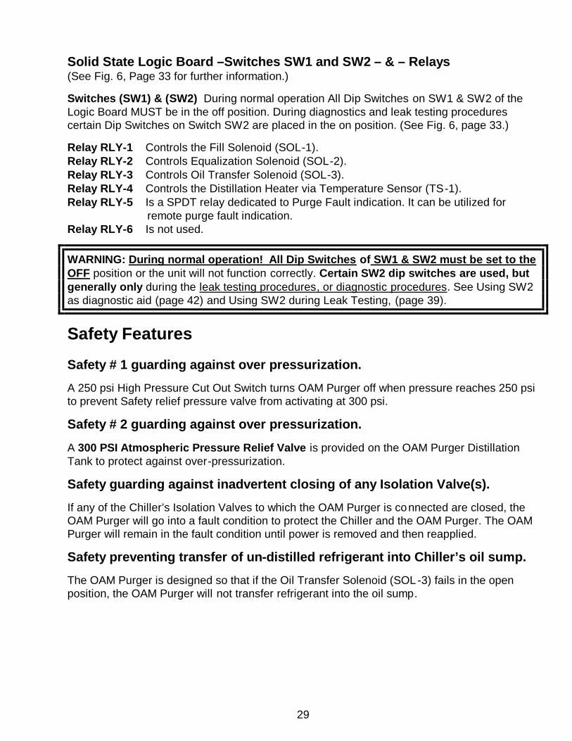
Solid State Logic Board –Switches SW1 and SW2 – & – Relays (See Fig. 6, Page 33 for further information.) Switches (SW1) & (SW2) During normal operation All Dip Switches on SW1 & SW2 of the Logic Board MUST be in the off position. During diagnostics and leak testing procedures certain Dip Switches on Switch SW2 are placed in the on position. (See Fig. 6, page 33.) Relay RLY-1 Controls the Fill Solenoid (SOL-1). Relay RLY-2 Controls Equalization Solenoid (SOL-2). Relay RLY-3 Controls Oil Transfer Solenoid (SOL-3). Relay RLY-4 Controls the Distillation Heater via Temperature Sensor (TS-1). Relay RLY-5 Is a SPDT relay dedicated to Purge Fault indication. It can be utilized for remote purge fault indication. Relay RLY-6 Is not used.
WARNING: During normal operation! All Dip Switches of SW1 & SW2 must be set to the OFF position or the unit will not function correctly. Certain SW2 dip switches are used, but generally only during the leak testing procedures, or diagnostic procedures. See Using SW2 as diagnostic aid (page 42) and Using SW2 during Leak Testing, (page 39).
Safety Features Safety # 1 guarding against over pressurization.
A 250 psi High Pressure Cut Out Switch turns OAM Purger off when pressure reaches 250 psi to prevent Safety relief pressure valve from activating at 300 psi.
Safety # 2 guarding against over pressurization.
A 300 PSI Atmospheric Pressure Relief Valve is provided on the OAM Purger Distillation Tank to protect against over-pressurization.
Safety guarding against inadvertent closing of any Isolation Valve(s).
If any of the Chiller’s Isolation Valves to which the OAM Purger is connected are closed, the OAM Purger will go into a fault condition to protect the Chiller and the OAM Purger. The OAM Purger will remain in the fault condition until power is removed and then reapplied.
Safety preventing transfer of un-distilled refrigerant into Chiller’s oil sump.
The OAM Purger is designed so that if the Oil Transfer Solenoid (SOL-3) fails in the open position, the OAM Purger will not transfer refrigerant into the oil sump.
30
Safety guarding against Fill Solenoid (SOL-1) failing in the open, or closed position. The OAM Purger is programmed to determine if the Fill Solenoid Valve (SOL -1) fails in the open or closed position. If either occurs, the OAM Purger will go into a fault condition to protect the Chiller and the OAM Purger. The OAM Purger will remain in the fault condition until power is removed and then reapplied. Safety guarding against Equalization Solenoid (SOL-2) failing in the open, or closed position. The OAM Purger is programmed to determine if the equalization solenoid (SOL -2) fails in the open or closed position. If either occurs, the OAM Purger will go into a fault condition to protect the Chiller and the OAM Purger. The OAM Purger will remain in the fault condition until power is removed and then reapplied. Safety guarding against the oil transfer Solenoid (SOL-3) failing in the open position. The OAM Purger is programmed to determine if the oil transfer Solenoid (SOL -3) fails in the open position. If this occurs, the OAM Purger will go into a fault condition to protect the Chiller and the OAM Purger. The OAM Purger will remain in the fault condition until power is removed and then reapplied. Safety guarding Against Temperature Sensor (TS-1) failing. The OAM Purger is programmed to determine if the Temperature Sensor ( TS-1) fails. If this occurs, the OAM Purger will go into a fault condition to protect the Chiller and the OAM Purger. The OAM Purger will remain in the fault condition until power is removed and then reapplied. Safety guarding against Solid State Logic Board Relays sticking or not making. The OAM Purger is programmed to determine if the Relays on the Solid State Logic Board are either welded shut or if they fail to make. If this occurs, the OAM Purger will go into a fault condition to protect the Chiller and the OAM Purger. The OAM Purger will remain in the fault condition until power is removed and then reapplied. Safety guarding against the heater failing in, ON position, or OFF position. If the Heater fails in the ON position, or if the Heater does no t work, the OAM Purger will go into a fault condition to protect the Chiller and the OAM Purger. The OAM Purger will remain in the fault condition until power is removed and then reapplied.
31
Electrical Control Box The Electrical Control Box contains the Solid State Logic Board, Temperature Sensor (TS-1) and terminal strip and the 250 PSIG Pressure Cut Out Switch (HPC-1). On top of the Control Box are the ON-OFF lighted rocker switch and the Red “FAULT” light. Terminal Block (TB-1) Terminal Block (TB-1) is used for control wiring and for providing convenient termination for unit power wiring. Temperature Sensor (TS-1) Temperature Sensor (TS-1) controls the Distillation Heater and limits oil temperature in the Distillation Tank to 155 degrees F. 250 PSIG Pressure Cut Out Switch (HPC-1) High Pressure Cut Out Switch terminates OAM Purger operation when pressure in the OAM Purger Distillation Tank exceeds 250 Psi. Used to protect the OAM Purger and the Chiller from over pressurization. Figure 5. – Major Components Electrical Box
Solid State Logic Board
Terminal Block (TB-1)
250 Psi High Pressure Cut out Switch (HPC-1)
Temperature Sensor (TS-1)
32
Logic Board Relays and Dip Switches (See Figure 6, on page 33) Relay RLY-1 Controls the Fill Solenoid Valve (SOL-1) Relay RLY-2 Controls Equalization Solenoid Valve (SOL-2). Relay RLY-3 Controls Oil Transfer Solenoid Valve (SOL-3). Relay RLY-4 Controls the Distillation Heater via Temperature Sensor (TS-1). Relay RLY-5 A SPDT relay dedicated to Purge Fault indication. It can also be utilized for remote indication. Relay RLY-6 Not used. Switches (SW1) & (SW2) (dip switches) Switches (SW1) & (SW2) During normal operation All Dip Switches on SW1 & SW2 of the Logic Board MUST be in the off position. During diagnostics and leak testing procedures certain Dip Switches on Switch SW2 are placed in the on position. (See Fig. 6, page 33.)
WARNING: During normal operation All Dip Switches of SW1 & SW2 must be set to the OFF position, or the unit will not function correctly. Certain SW2 dip switches are used, but generally only during the leak testing procedures, or for diagnostic aids, See using SW2 as diagnostic aid (page 42) and using SW2 during Leak Testing, (page 39).
33
Figure 6. – Solid State Logic Circuit Board
Neutral Connection
Temperature Sensor TS-1
Input 1
Display D1 Fill Phase LED
Indicator
Line voltage Wire L1
Logic Board Fuse ½ amp
Display D2 Distillation
Phase LED or Fault
Indicator
Display D3 Oil Transfer LED or Fault
Indicator
Display D5 Liquid Level High Sensor,
activated Indicator
Display D6 RED LED
With GREEN LED
FAULT INDICATOR
SWITCH SW2 Dip Switches 1, 2, 3 and 4 may be used for diagnostics 1, 2 and 3 are be used during leak testing (See pages 39 and 40 for explanation of when to use during leak testing.)
RLY-4 Relay Heater
RLY-1 Relay
Fill Solenoid (SOL-1)
RLY-3 Relay
Oil Transfer Solenoid (SOL-3)
RLY-5 Relay
Fault Indicator
RLY-6 Relay
NOT USED
RLY-2 Relay
Pressure Equalization
Solenoid (SOL-2)
Input 2 Liquid Level switch &
bleed resistor lead connection
Optional Run Signal
Input 6
Terminal J22
Isolated neutral
For Optional
Run signal
Display D4 Heater ON
LED or Fault indicator
SWITCH SW1 Dip Switch 6 enables Chiller “Run
Signal” Requirement Option.
Neutral Connection
Ground Connector
34
Figure 7. – Major Components of OAM Purger (Also See Next Page)
EZ Change Refrigerant Filter
Quick Change Coupling with
Automatic Flow Shutoff Valve
Base
Heater
High Pressure Cut Out Switch
Refrigerant Fill Solenoid (SOL-1)
Oil Transfer Solenoid (SOL-3)
Refrigerant Vapor Line Connection to Chiller
Evaporator
Line Connection to Chiller Charging Valve (Outlet of Fill Solenoid)
Equalization Solenoid (SOL-2)
Line Connection to Oil Sump
(Outlet of oil transfer Solenoid)
Pressure Equalization Check Valve
Liquid Level High Optical Sensor
Electrical Box
Sight Glasses
Schrader Valve Location
(Actual valve Not visible)
Safety Relief Valve
Location (Actual valve Not visible)
35
Figure 7. – (continued) Major Components of OAM Purger
Power and Reset Switch
Fault Warning Light
Distillation Tank
Equalization Solenoid (SOL-2)
Oil Return Line
Connection
Temperature Sensor (TS-1) Bulb,
Bulb Well & Capillary
Tube
Oil Transfer Solenoid (SOL-3)
Refrigerant Fill Line
Connection To Chiller
Charging Valve
Refrigerant Fill Solenoid (SOL-1)
Pressure Equalization Check Valve
Refrigerant Vapor Line
Connection to Chiller
Liquid Level High Optical Sensor
36
MAINTENANCE This section discusses the OAM Purger system maintenance requirements and procedures, electrical wiring diagram, basic OAM Purger troubleshooting procedures and leak testing procedure. The following maintenance procedures are required to assure efficient and reliable operation of the OAM Purger.
WARNING: Certain servicing procedures may expose you to harmful materials and dangerous conditions. To minimize the possibility of injury, follow safety procedures and instructions described in this manual, on product labels and provided in material safety data sheets.
EZ Change Refrigerant Filter Dryer Replacement Instructions Most centrifugal Chillers have no means for removal of harmful oil, moisture and acids from the refrigerant. Typically, oil, moisture and acids are allowed to accumulate in the refrigerant until a refrigerant analysis indicates they have reached dangerous levels and it is time to do something about them. Usually this means either replacing the entire refr igerant charge or removing the charge and distilling it back into the Chiller. Leaving moisture, acid and oil in the Chiller’s refrigerant charge not only subjects the Chiller to unnecessary harmful conditions, it is not a very cost-effective way to maintain a centrifugal Chiller. The purpose of the OAM Purger is not just to remove oil from the Chiller’s refrigerant. It removes moisture and acids as well. In fact, the OAM Purger is the most effective means, if not the only means, of continually purging harmful moisture and acids from a centrifugal Chiller. The OAM Purger will continue removing oil from the refrigerant after the filter -dryer is saturated. However, the OAM Purger can only remove moisture and acids as long as the EZ Change filter-dryer is fresh and active. The EZ Change Refrigerant Filter-Drier should be changed about every three months. A place has been provided on the filter-dryer label to record the date the filter-dryer was installed. Although three months may seem like a short time, you must remember that the OAM Purger processes approximately between 850 and 1250 pounds of liquid refrigerant per week. This means that during each three month period the OAM Purger will have processed (removed moisture and acids) from between 10,000 to 15,000 pounds of refrigerant.
The OAM Purger incorporates an integral self-sealing ball-check valve between the
37
filter-dryer and the Purger Distillation Tank. When the filter-dryer is unscrewed and removed, the ball-check valve closes off the flow path from the distillation tank preventing either refrigerant from escaping or air from being drawn in. The EZ Change Filter-Dryer requires much less time for change-out than a typical in-line filter-dryer. NOTE: Although the OAM Purger unit self-seals when the EZ Change Filter-Dryer is removed, a small amount (de minimus) of pressure release from dryer canister should be anticipated when removing. Steps for Changing EZ Change Filter-Dryer 1. Turn unit power switch to “OFF” position. 2. Using appropriate wrenches, loosen filter dryer.
3. SLOWLY unscrew and remove spent filter dryer. 4. Immediately install new filter dryer. (Use small amount of O-ring lubricant on each O-ring.) 5. Using wrenches, gently tighten. DO NOT over-tighten. 6. Turn unit power switch back to “ON” position.
WARNING: Always complete filter change-out. Never leave OAM Purger Unit unattended with filter port open. Unit WILL NOT function with filter dryer removed.
NOTE: Upon power-up, the OAM Purger will always initiate operation in a Fill Phase of the operating cycle. Periodic Maintenance Quarterly 1. Replace the EZ Change Refrigerant Filter Dryer.
2. Visually inspect the Purger.
38
Annually 1. Replace the EZ Change Filter-Dryer if due (see last replacement date indicated on label).
2. Replace the High Acid Capacity Oil Filter. The oil filter also has a place on the label to record the replacement date. It is essential that the Oil Filter be replaced at least once a year. However, semi-annual replacement is preferred.
3. Visually inspect the Purger.
Control Calibration
Temperature Sensor TS-1 General instructions on maintenance and adjustments. Avoid sharp bends or kinks in the capillary tube. Do not allow capillary tube to rub and abrade against any moving surface. Avoid constant bending of the tubing to avoid work hardening effects. The readings on the temperature sensor are a guide only. A separate thermometer must be used for exact adjustment of the set points. The temperature sensor in your OAM Purger came adjusted by use of a separate thermometer. The setting as it appears on the temperature sensor may not exactly correspond to the actual set point of 155 degrees F. 1. Use a flat screwdriver or a ¼” refrigeration (square) wrench to adjust set points.
2. Adjust the upper set point using the range spindle (the spindle to the left as you look at it).
3. Adjust the lower set point by turning the differential spindle (the spindle to the right as you look at it).
UPPER SET POINT (minus) DIFFERENTIAL (equals) LOWER SET POINT
High Acid Capacity Oil Filter
39
LEAK TESTING PROCEDURES
DIP Switch SW2 switches 1, 2 and 3 must be ON during leak testing procedure. (See Fig. 6, page 33 for location of Switch SW2.)
WARNING: During the leak testing procedure ALL VALVES supplying the OAM PURGER MUST BE CLOSED.
Switching SW2’s Dip switches 1, 2 and 3 ON opens all the OAM Purger’s solenoid valves so their respective lines can be tested for leaks .
1. Dip Switch 1 ON…energizes Fill Solenoid (SOL-1) and opens OAM Purger tank and line up to the Chiller Charging Valve. (Green D1 LED on solid.)
2. Dip Switch 2 ON…energizes Equalization Solenoid (SOL-2) and opens OAM Purger tank and line up to the Evaporator Valve. (Green D2 LED on solid.)
3. Dip Switch 3 ON…energizes Oil Return Solenoid (SOL-3) and opens OAM Purger tank and line up to the Oil Sump valve. (Green D3 LED on solid.)
WARNING: Be sure DIP Switches 1, 2 and 3 on SW2 are returned to the OFF position when finished with the leak test. If either of these DIP Switches are left in the ON position, the OAM Purger will not function properly. (See Fig. 6, page 33 for location of Switch SW2.)
Leak Testing OAM Purger when installed on Chillers using LOW PRESSURE REFRIGERANTS. (See page 40 for leak test procedure on chillers using High pressure refrigerants.) ALL chiller valves to OAM Purger MUST remain CLOSED during this procedure unless. To properly leak test the entire OAM Purge system you will have to pressurize the OAM Purger Unit including all fittings and piping connections up to the Chiller’s Valves.
1) Remove control box cover and flip DIP-switches 1, 2 and 3 on SW2 to the ON position (See Figure 6, page 33 for location of SW2 and Dip Switches 1, 2 and 3). This will energize all three Purger Unit solenoid valves allowing interconnecting lines to chiller to be pressurize.
2) Connect a pressure source, such as nitrogen, to the shrader port on the top of the Purger Filter Drier. (See Figure 7, page 34 for location.)
3) Pressurize OAM Purger to approximately 40 psig.
40
4) Turn OAM Power Switch to ON. 5) Leak test entire OAM Purger system. 6) Repair any leaks. 7) Once the leak test procedure is complete, bleed off test pressure and evacuate entire
OAM Purge system. Because of the various check valves in the OAM system the only way the entire system can be evacuated is by connecting the vacuum pump to the oil charging valve adapter shrader valve.
8) Once evacuation is complete, turn Unit Power Switch OFF. 9) Flip SW2 DIP switches 1, 2 and 3 back to the OFF position. 10) OPEN all Chiller Valves to OAM Purger. 11) Turn OAM Purger Power Switch back to the ON position. The OAM Purger is now in
operation.
NOTE: Any time power is applied or re-applied to the OAM, (after a 5 second delay, indicated by 5 green blinking LEDs) the OAM Purger always starts in a Fill Phase. After the 5 second programmed delay the D1 green LED should begin flashing. Leak Testing OAM Purger when installed on Chillers using HIGH PRESSURE REFRIGERANTS. (See page 39 for leak test procedure on chillers using Low pressure refrigerants.)
ALL chiller valves to OAM Purger MUST remain CLOSED during this procedure EXCEPT when otherwise instructed as part this procedure. 1. Connect refrigeration manifold gauge to the ¼” shrader valve. (See Figure 7, page 34.)
2. With power to OAM Purger OFF remove cover from control panel. On the solid-state logic control board locate DIP-Switch SW2. (See Figure 6, page 33 for dip-switch SW2 location.) Flip switches 1, 2 and 3 to the ON position. This will energize all three OAM Purger solenoid valves when power is applied.
3. Replace control panel cover and turn power switch ON. Solenoid valves (SOL-1), (SOL-2) and (SOL-3) should now be energized.
4. Now, while monitoring the refrigeration gauge, slowly and carefully crack open the
refrigerant “FILL” Line valve on the chiller and allow chiller pressure to pressurize the OAM system to approximately 40 psig and re-close valve. The entire purge system including the FILL line, Vapor Return line, Oil Return line (and the temporary oil recovery cylinder if installed) will be pressurized.
41
5. Using appropriate leak-testing method, leak test entire OAM System including all interconnecting lines, fittings, etc. Fix and repair any leaks.
6. Once you are certain there are NO leaks, turn OFF power and flip Dip switches 1, 2 and 3 back to the OFF position.
7. RE-OPEN ALL CHILLER VALVES.
8. Turn power ON. The OAM Purger is now in operation. OAM Purger Evacuation Procedure ALL chiller valves to OAM Purger MUST remain CLOSED during this procedure EXCEPT when otherwise instructed as part this procedure. 1. Due to system check valves the only way the entire OAM System can be completely
evacuated is by connecting the vacuum pump to oil sump valve adapter shrader valve. (see figure 1 page 14 for location).
2. Flip Dip switches 1, 2 and 3 on SW2 to the ON position. 3. Turn power ON to OAM and evacuate. 4. Once evacuation is complete close valve on gauge manifold set and remove vacuum
pump. Leave manifold gauges closed and connected to oil return shrader valve. 5. Again, while monitoring the refrigeration gauge, slowly and carefully crack open the
refrigerant “FILL” Line valve on the chiller and allow chiller pressure to pressurize the OAM system to approximately ½ psig.
6. Now, disconnect refrigeration gauges and cap the shrader valve. 7. Turn OAM Power Switch OFF and flip switch SW2’s dip switches 1, 2 and 3 to the OFF
position. 8. RE-OPEN all three (3) chiller valves to the OAM Purger. 9. Turn OAM Power Switch to ON position. The power switch “Green” indicator light should
now be energized. The OAM Purger is now in operation.
NOTE: Any time power is applied or re-applied to the OAM, (after a 5 second delay, indicated by 5 green blinking LEDs) the OAM Purger always starts in a Fill Phase. After the 5 second programmed delay the D1 green LED should begin flashing.
42
TROUBLE SHOOTING
Should an operational difficulty or malfunction occur, the diagnostic chart and checkout procedures on the following pages should help to quickly determine the cause and corrective action. The Troubleshooting Chart has a "Symptom" column which describes what the unit is doing; a "Possible Cause" column which identifies possible sources of the problem; and a "Solution" column which describes what must be done to correct the problem.
NOTE: Should the OAM Purger shut down on a FAULT condition, DO NOT POWER OFF THE PURGER until you have first removed its electrical panel cover and recorded the status of the green indicator LED’s D1 through D5 located on the Logic Board . Knowing the particular LED(s) that are lighted will help you diagnose the cause of the problem. Once the unit is powered off, this information will be lost. Retain the record of the LED readings. Examine the purger for any apparent problems, check the troubleshooting section for possible causes of the fault. Check to see if all appropriate Dip Switches on SW1 & SW2 are off (see pages 33, 39 & 42), then if there is no apparent problem, reset power. See if the fault repeats.
Using Switch SW2 Dip Switches as a diagnostic aid Switch SW2 Dip Switches can be used to activate the solenoid valves and distillation heater for various procedures. This can be very helpful when diagnosing and or correcting certain operational problems. By switching the appropriate DIP Switch to the ON position, the corresponding valve or heater will energize. 1. SW2 switching Dip Switch 1 ON……..energizes Fill Solenoid (SOL-1), Green D1 LED will be on solid. 2. SW2 switching Dip Switch 2 ON……..energizes Equalization Solenoid (SOL-2), Green D2 LED will be on solid. 3. SW2 switching Dip Switch 3 ON……. energizes Oil Return Solenoid (SOL-3), Green D3 LED will be on solid. 4. SW2 switching Dip Switch 4 ON……..energizes the Distillation Heater and the Green D4 LED will be on solid.
WARNING: Be sure DIP Switches, 1, 2, 3 and 4 on Switch SW2 are returned to the OFF position when finished. If any of these DIP Switches are left in the ON position, the OAM Purger will not function properly. (See Fig. 6, page 33 for location of Switch SW2.)
43
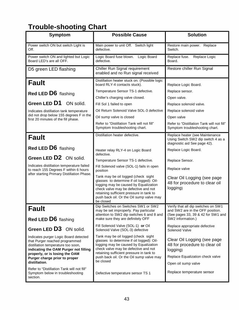
Trouble-shooting Chart Symptom Possible Cause Solution
Power switch ON but switch Light is Off.
Main power to unit Off. Switch light defective.
Restore main power. Replace Switch.
Power switch ON and lighted but Logic Board LED’s are all OFF.
Logic Board fuse blown. Logic Board defective.
Replace fuse. Replace Logic Board.
D5 green LED flashing Chiller Run Signal requirement enabled and no Run signal received
Restore chiller Run Signal
Fault
Red LED D6 flashing
Green LED D1 ON solid. Indicates distillation tank temperature did not drop below 155 degrees F in the first 20 minutes of the fill phase.
Distillation heater stuck on. (Possible logic board RLY-4 contacts stuck).
Temperature Sensor TS-1 defective.
Chiller’s charging valve closed.
Fill Sol 1 failed to open
Oil Return Solenoid Valve SOL-3 defective
Oil sump valve is closed
Refer to “Distillation Tank will not fill” Symptom troubleshooting chart.
Replace Logic Board.
Replace sensor.
Open valve.
Replace solenoid valve.
Replace solenoid valve
Open valve
Refer to “Distillation Tank will not fill” Symptom troubleshooting chart.
Fault Red LED D6 flashing
Green LED D2 ON solid. Indicates distillation temperature failed to reach 155 Degrees F within 6 hours after starting Primary Distillation Phase.
Distillation heater defective.
Heater relay RLY-4 on Logic Board defective.
Temperature Sensor TS-1 defective.
Fill Solenoid valve (SOL-1) fails in open position
Tank may be oil logged (check sight glasses to determine if oil logged): Oil-logging may be caused by Equalization check valve may be defective and not retaining sufficient pressure in tank to push back oil. Or the Oil sump valve may be closed
Replace heater (see Maintenance Using Switch SW2 dip switch 4 as a diagnostic aid See page 42).
Replace Logic Board.
Replace Sensor. Replace valve Clear Oil Logging (see page 48 for procedure to clear oil logging)
Fault Red LED D6 flashing
Green LED D3 ON solid. Indicates purger Logic Board detected that Purger reached programmed distillation temperature too soon, indicating the OAM Purger not filling properly, or is losing the OAM Purger charge prior to proper distillation.
Refer to “Distillation Tank will not fill” Symptom below in troubleshooting section.
Dip Switches on Switches SW1 or SW2 may be set improperly. Pay particular attention to SW2 dip switches 6 and 8 and make sure they are definitely OFF
Fill Solenoid Valve (SOL-1) or Oil Solenoid Valve (SOL-3) defective
Tank may be oil logged (check sight glasses to determine if oil logged): Oil-logging may be caused by Equalization check valve may be defective and not retaining sufficient pressure in tank to push back oil. Or the Oil sump valve may be closed Defective temperature sensor TS 1
Verify that all dip switches on SW1 and SW2 are in the OFF position. (See pages 33, 39 & 42 for SW1 and SW2 information.) Replace appropriate defective Solenoid Valve
Clear Oil Logging (see page 48 for procedure to clear oil logging)
Replace Equalization check valve Open oil sump valve Replace temperature sensor
44
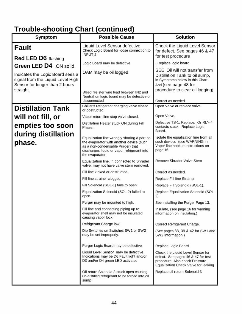
Trouble-shooting Chart (continued) Symptom Possible Cause Solution
Fault Red LED D6 flashing
Green LED D4 ON solid.
Indicates the Logic Board sees a signal from the Liquid Level High Sensor for longer than 2 hours straight.
Liquid Level Sensor defective Check Logic Board for loose connection to INPUT 2 Logic Board may be defective OAM may be oil logged Bleed resister wire lead between IN2 and Neutral on logic board may be defective or disconnected
Check the Liquid Level Sensor for defect. See pages 46 & 47 for test procedure
, Replace logic board
SEE Oil will not transfer from Distillation Tank to oil sump, in Symptoms below in this Chart And (see page 48 for procedure to clear oil logging)
Correct as needed
Distillation Tank will not fill, or empties too soon during distillation phase.
Chiller’s refrigerant charging valve closed or obstructed.
Vapor return line stop valve closed.
Distillation Heater stuck ON during Fill Phase.
Equalization line wrongly sharing a port on the evaporator with another device (such as a non-condensable Purger) that discharges liquid or vapor refrigerant into the evaporator.
Equalization line, if connected to Shrader valve, may not have valve stem removed.
Fill line kinked or obstructed.
Fill line strainer clogged.
Fill Solenoid (SOL-1) fails to open.
Equalization Solenoid (SOL-2) failed to open.
Purger may be mounted to high.
Fill line and connecting piping up to evaporator shell may not be insulated causing vapor lock.
Refrigerant Charge low.
Dip Switches on Switches SW1 or SW2 may be set improperly.
Purger Logic Board may be defective
Liquid Level Sensor may be defective Indications may be D6 Fault light and/or D3 and/or D4 green LED activated
Oil return Solenoid 3 stuck open causing un-distilled refrigerant to be forced into oil sump
Open Valve or replace valve.
Open Valve.
Defective TS-1, Replace. Or RLY-4 contacts stuck. Replace Logic Board.
Isolate the equalization line from all such devices (see WARNING in Vapor line hookup instructions on page 16.
Remove Shrader Valve Stem
Correct as needed.
Replace Fill line Strainer.
Replace Fill Solenoid (SOL-1).
Replace Equalization Solenoid (SOL-2).
See installing the Purger Page 13.
Insulate, (see page 16 for warning information on insulating.)
Correct Refrigerant Charge.
(See pages 33, 39 & 42 for SW1 and SW2 information.)
Replace Logic Board
Check the Liquid Level Sensor for defect. See pages 46 & 47 for test procedure. Also check Pressure Equalization Check Valve for leaking
Replace oil return Solenoid 3
45
Trouble-shooting Chart (continued) Symptom Possible Cause Solution
Heater fails to heat. See using Switch SW2 Dip Switches as diagnostics aid on page 42 (dip switch 4)
Defective Heater.
RLY-4 relay defective.
Disconnected lead.
Defective Temperature Sensor TS-1 Contacts stuck closed.
Defective Logic Board.
Replace heater (See Maintenance Section on Using Switch SW2 DIP switch 4 as a diagnostic aid. See page 42 for SW2 information)
Replace Logic Board.
Reconnect lead.
Replace Sensor.
Replace Logic Board.
Fill Solenoid Valve (SOL-1) fails to open or close See using Switch SW2 Dip Switches as diagnostics aid on page 42 (Dip switch 1)
SOL-1 Solenoid Valve defective.
RLY-1 relay defective.
Disconnected lead.
Solenoid seat may be contaminated
Replace valve.
Replace Logic Board.
Reconnect lead.
Replace Solenoid
Equalization Solenoid Valve (SOL-2) fails to open or close. See using Switch SW2 Dip Switches as diagnostics aid on page 42 (Dip switch 2)
SOL-2 Solenoid Valve defective.
RLY-2 relay defective.
Disconnected lead.
Solenoid seat may be contaminated
Replace valve.
Replace Logic Board.
Reconnect lead.
Replace Solenoid
Oil transfer Solenoid Valve (SOL-3) fails to open or close. See using Switch SW2 Dip Switches as diagnostics aid on page 42 (Dip switch 3)
SOL-3 Solenoid Valve defective.
RLY-3 relay defective.
Disconnected lead.
Solenoid seat may be contaminated
Replace valve.
Replace Logic Board.
Reconnect lead.
Replace Solenoid
Oil will not transfer from Distillation Tank to oil sump.
Or procedure to follow if unit is oil logged Clear Oil Logging (see page 48 for procedure to clear oil logging
SOL-3 Solenoid Valve defective.
Oil Sump valve closed.
Oil return line kinked or blocked.
Oil Filter blocked.
Logic board RLY-3 relay defective.
Equalization Solenoid Valve SOL-2 stuck open or leaking past valve seat.
Pressure Equalization Check Valve defective and leaking and not retaining pressure for oil push back
Oil Check Valve CK-1 stuck closed
Tank may be oil logged (check sight glasses to determine if oil logged): Oil-logging may be caused by Equalization check valve may be defective and not retaining sufficient pressure in tank to push back oil. Or Oil sump valve may be closed
Replace valve.
Open Valve.
Correct as necessary.
Replace oil filter.
Replace Logic Board.
Replace valve.
Replace Pressure Equalization Check Valve
Replace oil Check Valve CK-1
Clear Oil Logging (see page 48 for procedure to clear oil logging)
FOR INFORMATION ABOUT FACTORY REPAIR 317-865-4130
46
TROUBLESHOOTING THE LIQUID LEVEL SENSOR Preliminary Test: 1) Turn OAM Power Switch OFF. 2) While observing the LEDs on OAM Logic Board; turn OAM Power Switch back ON. Normal Result (A) LED D1 ON Blinking; indicates the OAM liquid level sensor is functioning properly and the OAM Unit is operating in the FILL Mode. (So long as liquid is not present in the upper sight glass). Faulty Result (B)… LEDs D2 ON Blinking, D4 and D5 ON SOLID; means either the Liquid Level Sensor has erroneously detected a liquid level and is therefore defective, or the Logic Board is defective. To determine which component is at fault proceed with the following test: 1) Again, turn OAM Power Switch OFF. 2) Disconnect the Yellow level sensor wire and the Blue Bleed Resistor wire from Input
Terminal IN2 on the OAM Logic Board. This eliminates the Level sensor from the circuit. 3) Turn the OAM Power Switch back ON. Determination (1) LED D1 ON Blinking; indicates the Logic Board is responding correctly therefore the problem is the Liquid Level Sensor. Proceed to Liquid Level Sensor Replacement Instructions on page 47. Determination (2) Any other result indicates a bad board. Board must be replaced. (When replacing Board do not forget to re-connect the Yellow level sensor wire and the Blue Bleed Resistor wire to Input Terminal IN2 on the OAM Logic Board.)
47
Liquid Level Sensor Replacement Instructions
Liquid Level Sensor malfunction can result from either a defective Electronic Module or a cracked or cloudy Prism. A faulty Electronic Module is most likely causing the problem and therefore should be replaced first since it can be replaced quickly and easily without opening the refrigeration system. However, if after replacing the Electronic Module the Liquid Level Sensor still does not functio n properly then the Prism is probably at fault. A cracked or cloudy Prism can cause erratic response or no response at all to the presence of liquid.
It the Prism is defective the complete Liquid Level Sensor will have to be replaced. In order to replace the complete sensor it will be necessary to isolate and depressurize the OAM Distillation Tank. MODULE PRISM Replacing Level Sensor Switch Electronic Module…
1) Turn OAM Power Switch OFF. 2) Disconnect the white Liquid Level Sensor wire from TB-1 terminal 2, and the black sensor wire
from TB-1 terminal 5. 3) Disconnect the yellow sensor wire from the Bleed Resistor connected to Input terminal IN2 on
the Logic Board 4) Remove sensor wiring and conduit from electrical box. 5) Remove conduit and conduit connector from sensor. 6) Remove the Retaining Ring that holds the Electronic Module in place in the sensor body. This
will require a pair of IRR P-101 or equivalent snap ring pliers. 7) Remove the retainer 8) Using the module leads gently pull the defecti ve module and O-ring from the sensor body, being
careful not to loose the O-ring. 9) Insert the new replacement module with old O-ring into the sensor body. 10) Insert retainer and re-install retaining ring. 11) Re-connect sensor wires.
NOTE: It is imperative that the white wire be connected to TB-1 terminal 2 and the black wire be connected to TB-1 terminal 5. The yellow wire must be connected to the Blue Bleed Resistor wire and both must be connected to Logic Board Input terminal IN2.
48
PROCEDURE TO CLEAR OIL LOGGED DISTILLATION TANK
The following conditions can cause “oil logging” of the OAM Purger Distillation Tank: 1. The oil sump “Oil Charging” valve has been inadvertently left closed.
2. The “Oil Return” Solenoid Valve (SOL-3) fails in the closed position.
3. “Relay (RLY-3)” fails to energize Solenoid Valve (SOL-3) preventing oil return to oil sump.
4. The “Oil Return” line is kinked, or obstructed, preventing oil return to oil sump. 2 5. The Pressure Equalization Check Valve is defective preventing the OAM from retaining
pressure that is used to return oil to the oil sump during the oil return phase.
Should oil logging occur, clear the Distillation Tank using the following procedure: 1. Troubleshoot the purger to determine which of the above mentioned conditions has caused the oil
logging problem.
2. Correct the problem. Only after the problem has been corrected can you proceed to the next step.
3. Turn OFF power to purger.
4. Isolate the purger from the Chiller by closing all valves to purger: Refrigerant Charging Valve, Oil Sump Charging Valve and the Evaporator Gauge Stop Valve.
5. Remove cover from Electrical Panel, on Switch SW2 flip Dip Switch 3 to the ON position. (This procedure allows the Oil Return Solenoid Valve (SOL-3) ONLY to energize when power is reapplied.) (See Figure 6, on page 33 for location of SW2.)
6. Using a manifold gauge set, connect a pressure source, such as nitrogen, to the Shrader Access Fitting located near the top of the Distillation Tank. Pressurize the tank to approximately 5 psig.
7. Now, RE-OPEN the oil sump oil-charging valve.
8. Turn power to purger back ON.
9. The 5 psig pressure will now push the oil from the Distillation Tank back to the Chiller’s oil sump.
10. When the manifold gauge indicates 2 psig pressure in the Distillation Tank, enough oil has been transferred. Be sure to stop at 2 psig to prevent nitrogen from entering the Chiller.
11. Remove manifold gauge set from purger.
12. Turn power to purger back OFF again.
13. Flip SW2, dip switch 3 back to the OFF position. (See Figure 6, on page 33 for location of SW2.)
14. Use vacuum pump to evacuate the OAM Purger.
15. Place cover back on electrical panel.
16. OPEN ALL valves to purger.
17. Turn power to purger back ON. The OAM Purger should now function properly.
49
Figure 8. – Electrical wiring diagram
4 D2
Distillation Heater
IN1
IN7
IN6
IN2
WHT
Wiring SchematicModel OAM-200
BLK WHT
BLK
BLK
BLK
Equalizer
Oil Return
Fill
L1 LINE
NEUTRAL
GND
1
RLY-1NO
3
2
RLY-2NO
NO
RLY-3
RLY-4
WHT
WHT
BLK
BLK
BLK
SOL-2
SOL-3
SOL-1
Bleed Resistor
Run Signal Isolated NeutralBLU
BLU
Optional Chiller "Run Signal"
BLK
Optical Level Sensor
BLK
WHT
YEL
D1
5
5
LOGIC BOARDLOGIC BOARD
NO
RLY-5NC
COM
COM
NO
NO
NCRLY-6
BLK
BLK
FAULT
BLK
BLK
BLK
BLK
NO
NCHPC-1
COM
115 VAC
BLK
TB1
BLK BLK WHT
5
5
4
4
2
2 3
3 4
4
2
2
1
11
1 2
2
2 2B2A
TS-12
1
RED
4
D4
D3
D6
D5
WHT
WHT
WHT
NEUTRAL
5
5BLKBLK
GND
WHT
WHT
50
WARRANTY
Equipment Warranty Subject to the terms below, REDI CONTROLS will, within one year after date of purchase, repair any REDI CONTROLS’ product being used by the original purchaser, which is defective due to faulty materials or workmanship. REDI CONTROLS has the right to repair or replace a defective part or replace the entire product. To file a Warranty claim on any system or component, return the defective unit to the address below, or other location as REDI CONTROLS directs, freight prepaid. This Warranty does not apply to or cover:
• Damages beyond REDI CONTROLS’ control.
• Malfunctions that result from failure to properly install, operate or maintain a product in accordance with instructions provided by REDI CONTROLS.
• Failures of equipment due to abuse, accident or negligence.
• Damages from, or part failures due to equipment not being installed per REDI CONTROLS’ instructions, per applicable codes or ordinances, or in accordance with good trade practices.
• Labor or other charges incurred in removing or reinstalling any REDI CONTROLS product or part.
• Damages resulting from use of a REDI CONTROLS product for any purpose other than for which it was designed and manufactured.
• Any implied warranty of merchantability or fitness for any particular purpose, occurring after the Warranty Period.
• Loss of use, loss of time, inconvenience, rental for substitute products, loss of business, loss of income, or any other consequential damages resulting from use or failure of any REDI CONTROLS product.
Inquiries to: REDI CONTROLS at 755 E. Main Street, Greenwood, Indiana, 46143