Page 2 of 16 1145 2kW and 3kW SpeedControl 1145 is a drive for control of PMSM, BLDC motors - typical in compressors / up to 3000W / 3 x 14A 3 phase motors. For single phase supply, with build in EMC filter and without harmonic current on the supply. Compliant for use with A2L refrigerant Vertical mounting Coldplate mounting Horizontal mounting
Transcript
Page 2 of 16
1145 2kW and 3kW SpeedControl 1145 is a drive for control of PMSM, BLDC motors - typical in compressors / up to 3000W / 3 x 14A 3 phase motors. For single phase supply, with build in EMC filter and without harmonic current on the supply.
Compliant for use with A2L refrigerant
Vertical mounting
Coldplate mounting
Horizontal mounting
Page 3 of 16
Table of Content
Product Description 3
Warnings 4
Configuration Standard is ModBus 5
SpeedControl 1145 Must be Tuned for Specific Compressor / Motor 5
Compressor Models / Motors Already Profiled 5
How to Get Inverter Tuned for New Compressor Models 7
The 0-10V Add-on Print with Dip-switch Selection of Profile 8
The Power - Amp. (How?, Where?, What?) 9
Cooling 10
Configuration Examples 11
Choose the Right Product Number - Selection Guide 13
Diagram 14
Technical Data 15
WEEE, Applicable Standards etc. 16
Page 4 of 16
Product Description
SpeedControl 1145 is a single phased supplied drive for control of PMSM and BLDC and motors up to 3000W/ 3 x 14A. SpeedControl 1145 is enclosed in an IP 20 metal housing for demanding environments. The compact construction, very low sound level as there is no active fan in the drive and the fact that it is maintenance free makes it suitable for many applications. All parts are integrated in the drive which makes no external capacitors or inductors required. Active cooling is not included.
The SpeedControl 1145 has integrated APFC (Active Power Factor Correction). The APFC prevents the drive from contributing significantly to the harmonic currents on the grid which is a problem for many drives. Harmonic currents impair the reliability of the mains resulting in poor use of the grid and in house electrical installations. This is partly due to the fact that current and voltage are not in phase, but more so due to non-linear components that are used in all electronic products which generate a wide range of harmonic currents at 150Hz, 250Hz, 350Hz etc. etc., which should not be present in 50Hz installations. These harmonic currents accounts for a considerable loss of efficiency. To protect the grid there are a number of legislative regulations (EN61000-3-2) which must be observed when releasing a drive. Furthermore drives used in other type of products, particularly when these are used in domestic housing, drives are subject to strict requirements to ensure high efficiency (ECO design) and efficient exploitation of the building installations. These requirements can be met in various ways depending on the size of the drive. Therefore we also offer several solutions including an APFC which by using an advanced power entry enhances our largest frequency converter, offering a very high performance and a cost-efficient use of the electrical installation.
To reduce the overall cost and minimize installation work, an APFC has been integrated in SpeedControl 1145. This makes SpeedControl 1145 an all-in-one solution which also includes an EMC filter to ensure that we also meet the requirements of the EMC Directive.
Many manufacturers choose to use an A2L or A3L refrigerant to reduce the use of refrigerant with a high GWP (Global Warming Potential). The SpeedControl 1145 is designed to be in compliance with the IEC 60335-2-40:2016 with respect to the A2L refrigerants. It is also possible to use the SpeedControl 1145 for applications using A3L refrigerant all though it will require a close cooperation between LS Control and the manufacturer.
The SpeedControl 1145 range is a new series of unique PM motor drives designed for the growing market of energy saving units. It is also a sensor less drive – which makes mounting of sensors in the PM motor obsolete. The drive is available as standard with cold plate or heat sink for vertical or horizontal mounting.
Permanent magnet synchronous motors (PMSM) are highly efficient and widely used today for fans, compressors, pumps and other applications. Compared to conventional drives and AC motors, the new EC and attached PM motors are considerably energy saving, improving the efficiency of the finished unit significantly. PM motors have the flat characteristic that the torque is almost constant during the controllable speed range. These motors typically have an efficiency above 94% by using a correct drive. However, the rapid development within the technology and the motor is controlled by using of motors results in new and improved motors continuously. The SpeedControl 1145 employs the latest technology within sensor less FOC Sinusoidal motor currents control of PM motors. Motors must be matched to the drive for optimum performance and energy savings. A number of profiles are already available, but if the motor profile for a specific compressor is not available, there is a new tuning procedure making tuning to new compressor models and motor profiles available at any site, i.e. customer site, manufacturer site etc
Page 5 of 16
Warnings Before the drive is taken into use, verify that the specifications of the drive are compatible with the mains to which it is going to be connected. Furthermore verify that the motor is suitable for drive connection and that it is in compliance with the specifications of the drive. Check the place of installation for any special requirements and precautions which must be observed during installation, commissioning or operation. The drive must be supplied through a mains switch with at least 3mm breaker space between all conductors according to IEC364. The fuse installed in the electrical switchboard must be 16A or less for SpeedControl 1145. The drive must always be connected to yellow/green grounding conductor (PE) in supply. If the drive is connected to an installation with a residual current device as an extra protection, the device must be marked with minimum the following symbol: HPFI/PFI Class A Si
The components of the power unit of the drive are live when it is connected to mains. Coming
into contact with this voltage is extremely dangerous and may cause death or severe injury.
The control unit (connection 5-8) is isolated from the mains potential.
The motor terminals U, V and W are live when the drive is connected to mains, even when the motor is not running.
The HW Stop terminals 1 - 2 and LS terminals 3 - 4 are NOT isolated from the mains potential.
The earth leakage current may exceed 3.5 mA AC when the drive is connected to a motor.
According to standard EN61800-5-1 a reinforced protective ground connection must be mounted.
If the drive is part of a machine solution, the machine manufacturer is responsible for providing the machine with a main switch. (EN60204-1).
If the drive is disconnected from mains while the motor is running, high and dangerous voltage may still be present on the power unit of the drive. In this case the motor is operating as a generator supplying the drive with power.
After disconnecting the drive from mains, wait minimum 30 minutes before handling the drive.
The drive may automatically start the motor after a fault situation or after re-connection of
mains. Note that there might be a minimum downtime during which the motor cannot be stopped.
In a domestic environment this product may cause radio interference in which case supplementary mitigation measures may be required.
Intended for use in first environment, that includes domestic premises, it also includes
establishments directly connected without intermediate transformers to a low-voltage power supply network which supplies buildings used for domestic purpose.
Page 6 of 16
Configuration Standard is ModBus
SpeedControl 1145 is a ModBus configured product and an updated ModBus address list is found on the LS Control web page https://lscontrol.dk/en/products/frequency-converter-for-compressors
It is of most importance that the ModBus values are set correctly for a specific choice of compressor as an erroneous setting may in worst case corrupt the connected motor / compressor.
The below picture and drawing illustrates the placement of the ModBus clamps and the HW Stop Clamps.
SpeedControl 1145 Must be Tuned for Specific Compressor / Motor
For the SpeedControl 1145 to operate smoothly and effectively the motor data of the specific compressor must be entered correctly into the drive.
To ease this task, a number of motor profiles are already ready for use and can be selected by ModBus setting or via a small add-on device which enable motor selection to be done by dip-switch setting and also enable the drive to run using a 0-10V signal.
Compressor Models / Motors Already Profiled
Hence the number of compressor / motor profiles continuously will be rising a spread sheet is available at ›https://lscontrol.dk/da/produkter/frekvensomformere-til-kompressorer‹ which will be updated with all profiles on an on-going basis. The spread sheet is 2 parted - one part lists all compressor manufacturers and models available with which profile - the other part lists motor data in connection to the specific motor profiles.
Example of spread sheet for the compressor list with according motor profile for SpeedControl 1145
Page 7 of 16
Below example gives an idea of the structure of the spread sheet part showing the motor data in connection with the motor profiles. However, it must be kept in mind that this is only an example and do not represent all profiles available. Please refer to home page to get the complete list.
Example of spread sheet for motor data with according motor profile for SpeedControl 1145
Note; In the list of profiles for compressor models a classification system ranging from A to C and ’blank’ is used. A-classification is the highest rank, an A-classification is the result of a LS Control performed full range test on the compressor at LS Control test center. A B-classification is the result of the later described tuning procedure, where LS Control has supported an online tuning of a compressor under certain conditions and the expectation is that the profile will work well in other applications using the same compressor model. The lowest level, the C-classification, is a profile supplied by a customer who has tuned the compressor profile by himself and LS Control has no knowledge of the performance. Finally, ’blank’ classification is used for compressor models that share the same type of motor with another compressor model with a ranked profile but has not been tested on the specific compressor model. However, it is expected that the motor profile also will work on the new compressor model.
Nevertheless; It is always the responsibility of the customer to perform a full test at site to ensure that SpeedControl 1145 works well under any anticipated conditions in the specific application.
If the wanted motor profile is not available in the spread sheet on the home page, the drive must be tuned to a new profile fitting your specific motor / compressor model.
The SpeedControl 1145 may be tuned in the field at site by a technician in cooperation with support department in LS Control.
Page 8 of 16
How to Get SpeedControl 1145 Tuned for New Compressor Model / Motor Profile
It is important to contact LS Control in case the SpeedControl 1145 is to be used with a compressor model / motor type which is not in the spread sheet. In conjunction it is decided on how to proceed. If a classification B motor profile is to be made it is of most importance a SpeedControl 1145 is delivered in right model and with no tuning and below procedure is followed.
Customer has a PC with internet connection at site When there is a PC with internet connection at site LS Control will send an USB-Modbus connector to site (free of chage when returned to LS Control after tuning).
When the connector is received and the ’TeamViewer’ program has been downloaded and installed to the PC to be used, an appointment between Technician at site and LS Control Support department is made.
The ’TeamViewer’ is located at https://lscontrol.dk/en/about-us/support/ Please click the icon ’LS Control Support’ to install the TeamViewer on the PC to be used to tune the SpeedControl 1145.
Getting ready and performing the tuning process
Connect the SpeedControl 1145 to the compressor in the product application. Make sure not to connect the power supply, the 0-10V Signal print or any other parts (ModBus translators) must not in any way be connected to the ModBus interface no matter if it should be part of the final application.
Then connect the PC to the SpeedControl 1145 using the USB-Modbus connector. Call LS Control Support.
LS Control will take over the PC and run a test procedure via the TeamViewer. A customer technician must be available at site during the test procedure to turn on the power supply and to increase and decrease the load on the drive.
Page 9 of 16
When test procedure is completed successfully the drive has been tuned to this specific compressor model.
Customer is now able to continue their own testing of entire product / application using either ModBus or connect the 0-10V Signal print and test using a 0-10V signal.
In the meantime at LS Control the compressor model and motor will be given a profile number within the software for all future produced SpeedControl 1145s to include this profile making it able to run with this specific compressor model, only by selecting the profile number in the Modbus address or setting the dip-switch on the 0-10V print to the profile number of the specific compressor model.
Please note; Any stock of the SpeedControl 1145 delivered prior to the tuning must be returned to LS Control for software update before including the new compressor model or it may be updated by LS Control partner by using a special programmer which may be bought at LS Control.
Customer does not have a PC or does not have an internet connection at site
If customer doesn´t have a PC or an internet connection at the site where the tuning is to be performed, LS Control will provide a suitcase with all necessary equipment to hook up to LS Control Support.
The suitcase with equipment is provided free of charge under the terms that it is returned to LS Control after tuning the drive. Naturally the suitcase will include a detailed description on how to get the PC enclosed online on the internet and ready for LS Control Support to take over.
When content of suitcase has been set up the rest of the tuning procedure is as described above under the paragraph ’Getting ready and performing tuning’.
The 0-10V Add-on Print with Dip-switch Selection of Profile
As already described the SpeedControl 1145 is configured and controlled by ModBus as standard. However an add-on print is available which enables the drive to be configured with any known motor profile by using the dip-switches and furthermore the drive may then be controlled by a 0-10V signal.
0-10 V Add-on Print
Choose motor profile using the dip-switch.
Mount and click in to the hole above the Modbus terminals
Ready for operation
Must be chosen before mounting
Page 10 of 16
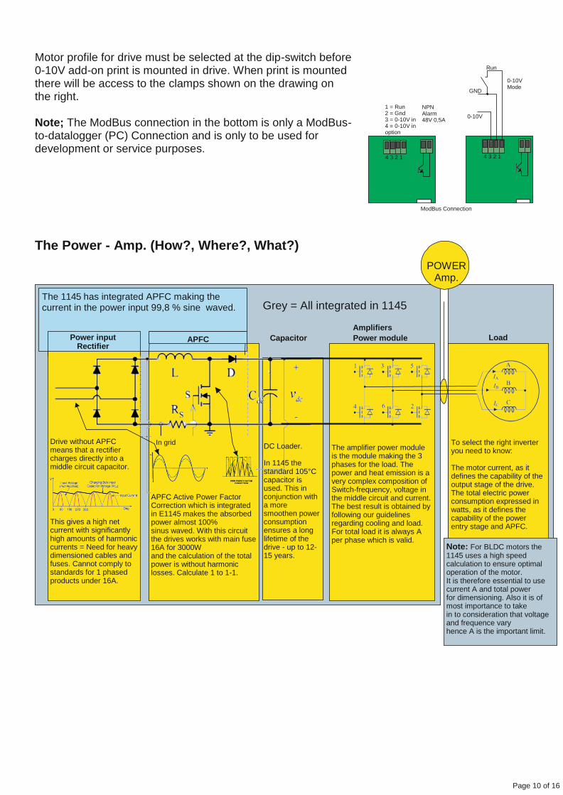
Motor profile for drive must be selected at the dip-switch before 0-10V add-on print is mounted in drive. When print is mounted there will be access to the clamps shown on the drawing on the right.
Note; The ModBus connection in the bottom is only a ModBus- to-datalogger (PC) Connection and is only to be used for development or service purposes.
1 = Run 2 = Gnd 3 = 0-10V in 4 = 0-10V in option
4 3 2 1
NPN Alarm 48V 0,5A
ModBus Connection
The Power - Amp. (How?, Where?, What?)
POWER
Amp.
The 1145 has integrated APFC making the current in the power input 99,8 % sine waved.
Grey = All integrated in 1145
Amplifiers
Capacitor Power module Load
DC Loader.
In 1145 the standard 105°C capacitor is used. This in conjunction with a more smoothen power consumption ensures a long lifetime of the drive - up to 12- 15 years.
The amplifier power module is the module making the 3 phases for the load. The power and heat emission is a very complex composition of Switch-frequency, voltage in the middle circuit and current. The best result is obtained by following our guidelines regarding cooling and load. For total load it is always A per phase which is valid.
To select the right inverter you need to know:
The motor current, as it defines the capability of the output stage of the drive. The total electric power consumption expressed in watts, as it defines the capability of the power entry stage and APFC.
Note: For BLDC motors the 1145 uses a high speed calculation to ensure optimal operation of the motor. It is therefore essential to use current A and total power for dimensioning. Also it is of most importance to take in to consideration that voltage and frequence vary hence A is the important limit.
Run
GND
0-10V Mode
0-10V
4 3 2 1
APFC Active Power Factor Correction which is integrated in E1145 makes the absorbed power almost 100% sinus waved. With this circuit the drives works with main fuse 16A for 3000W and the calculation of the total power is without harmonic losses. Calculate 1 to 1-1.
In grid
This gives a high net current with significantly high amounts of harmonic currents = Need for heavy dimensioned cables and fuses. Cannot comply to standards for 1 phased products under 16A.
Drive without APFC means that a rectifier charges directly into a middle circuit capacitor.
APFC Power input Rectifier
Page 11 of 16
Cooling
All drives must be cooled effectively to get the best results. Hence the placement of the drive must be taken into considerations to ensure the drive is able to get rid of the heat generation.
As a basic rule the drive generates up to 8% of the total power as heat dissipation. meaning if the total output is 1000W the drive generates up to 80W heat, at 3000W it is approx. up to 240W
The loss in the drives mainly originates from the rectifier, EMC interference components APCF - middle circuit and amplifier. Even though the newest technology for these components are used they still contribute to a loss. It is however also of influence at which switch frequency the connected load is operating at its best.
Note: If the drive is cooled by mounting on a heat exchanger it must be ensured that the surface of the heat exchanger is large enough to ensure sufficient cooling.
If the drive is mounted for use of air cooling it is important to ensure sufficient air speed passes through the heat sink. It is recommended that the air speed is at least 2 - 3 m/sec. at full load.
NOTE the drive turns it self down if it gets to hot. Giving that if sufficient cooling is not ensured you will experience reduced function of the equipment.
Configuration Examples
The next pages shows suggestions for mounting the SpeedControl 1145 within a unit. Please bear in mind that it is only examples and the SpeedControl 1145 can be used in many other applications.
Page 12 of 16
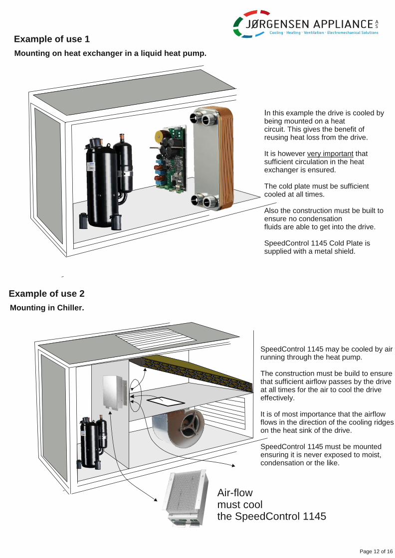
Example of use 1
Mounting on heat exchanger in a liquid heat pump.
In this example the drive is cooled by being mounted on a heat circuit. This gives the benefit of reusing heat loss from the drive.
It is however very important that sufficient circulation in the heat exchanger is ensured.
The cold plate must be sufficient cooled at all times.
Also the construction must be built to ensure no condensation fluids are able to get into the drive.
SpeedControl 1145 Cold Plate is supplied with a metal shield.
Example of use 2
Mounting in Chiller.
SpeedControl 1145 may be cooled by air running through the heat pump.
The construction must be build to ensure that sufficient airflow passes by the drive at all times for the air to cool the drive effectively.
It is of most importance that the airflow flows in the direction of the cooling ridges on the heat sink of the drive.
SpeedControl 1145 must be mounted ensuring it is never exposed to moist, condensation or the like.
Air-flow must cool the SpeedControl 1145
Page 13 of 16
Example of use 3
Mounting in out door heat pump unit.
SpeedControl 1145 may be cooled by air running through the heat pump.
The construction must be build to ensure that sufficient airflow passes by the drive at all times for the air to cool the drive effectively.
It is of most importance that the airflow flows in the direction of the cooling ridges on the heat sink of the drive.
SpeedControl 1145 must be mounted ensuring it is never exposed to moist,condensation or the like.
Cables and electronics must be mounted in enclosures for outdoor use and there must be a gasket for the lead-in of the heat sink.
Example of use 4
Mounting on Wall in a unit
SpeedControl 1145 may be cooled with air running down the wall.
Mount approx. 160cm above floor. With sufficient air the drive may be loaded with 1500W without active cooling.
It is important that the drive is mounted in a way which ensures that the air cools the drive effectively and sufficient airflow passes by the drive at full load.
SpeedControl 1145 must be mounted ensuring it is never exposed to moist, condensation or the like.
Cables and electronics must be mounted in an enclosure.
Heat pump or cooling unit
Page 14 of 16
Choose the Right Product Number - Selection Guide
2 KW
3 KW
28625 SpeedControl 1145 E 2KW LHS dc/dc
28650 SpeedControl 1145 E 3KW LHS dc/dc
2 KW
3 KW
2 KW
3 KW
2 KW
3 KW
2 KW
3 KW
2 KW
28620 SpeedControl 1145 E 2KW SHS dc/dc
28680 SpeedControl 1145 E 3KW SHS dc/dc
28630 SpeedControl 1145 E 3KW CP dc/dc
28655 SpeedControl 1145 E 3KW CP dc/dc
28627 SpeedControl 1145 2KW LHS dc/dc
28652 SpeedControl 1145 3KW LHS dc/dc
28622 SpeedControl 1145 2KW SHS dc/dc
28682 SpeedControl 1145 3KW SHS dc/dc
28632 SpeedControl 1145 3KW CP dc/dc
3 KW 28670 SpeedControl 1145 3KW CP dc/dc
Diagram
Page 9 of 11
APFC Coil
Supply Voltage
L3
L7 L4
L5
L6
1 2 3 4
5 = ModBus A 6 = Modbus B 7 = GND 8 = Supply in or out. Consult LS Control before using
Also see seperate Modbus document for description at www.lscontrol.dk
8
motor output Cable shield
must be connected with clamp
1 = HW1 hardware stop 2 = HW2 hardware stop 3 = LSC1. (Consult LS Control before using) 4 = LSC2. (Consult LS Control before using)
NOTE: All cables except for supply voltage must be shielded.
LED Explanation
L1 = Green run LED - Flashes when OK
L2 = Red Fault LED - ON when Fault
L3 = Yellow Fault Type LED - Flashes error number.
L4 = Yellow ModBus Communication LED - flashes fast
L5 = Yellow LED reserved for future use
L6 = Yellow LED reserved for future use
L7 = Red hardware stop LED - ON=Fault, Flashes=OK
HW Stop switch The inverter is supplied with a hardware (HW) Stop switch function. This HW Stop function can be used with a switch (e.g. a pressure switch or a thermal switch). The switch must be connected between connector HW1 and HW2 and it must be closed for the inverter to run the motor. If the switch is open the inverter is stopped and it will not be able to restart until the supply voltage has been disconnected long enough for the inverter to come to a complete stand still.
Note: Wires between connector and cable shield MUST be as short as possible. Motor cable should NOT cross or be placed together with other wires / cables.
The product complies with the requirements of the EMC directive 2014/30/EU, the Low Voltage Directive 214/35/EU and the RoHS Directive 2011/65/EU and carries the CE-marking
Safety: EN 61800-5-1:2007 - Adjustable speed electrical power drive systems - Part 5-1: Safety requirements - Electrical, thermal and energy.
EMC: EN 61800-3:2005 - Adjustable speed electrical power drive systems - Part 3: EMC requirements and specific test methods EN 61800-3/A1:2002 - Adjustable speed electrical power drive systems - Part 3:
WEEE Electrical and electronic equipment contains material which may be hazardous to human health and environment if it is not handled correctly at disposal.
Electrical and electronic equipment is marked with a crossed/out wheelie bin logo. This logo symbolises that electrical and electronic equipment must not be disposed together with normal household waste but must be collected separately.
Contact your local authorities for further information on disposal of equipment under the WEEE directive.