Database Logical Modeling MICROSOFT EXAM OBJECTIVES COVERED IN THIS CHAPTER: ✓ Define entities. Considerations include entity composition and normalization. ■ Specify entity attributes. ■ Specify degree of normalization. ✓ Design entity keys. Considerations include FOREIGN KEY constraints, PRIMARY KEY constraints, and UNIQUE constraints. ■ Specify attributes that uniquely identify records. ■ Specify attributes that reference other entities. ✓ Design attribute domain integrity. Considerations include CHECK constraints, data types, and nullability. ■ Specify scale and precision of allowable values for each attribute. ■ Allow or prohibit NULL for each attribute. ■ Specify allowable values for each attribute. Chapter 1 COPYRIGHTED MATERIAL
Transcript
Database LogicalModeling
MICROSOFT EXAM OBJECTIVES COVERED INTHIS CHAPTER:
✓ Define entities. Considerations include entity composition and
normalization.
■ Specify entity attributes.■ Specify degree of normalization.
✓ Design entity keys. Considerations include FOREIGN KEY
constraints, PRIMARY KEY constraints, and UNIQUE
constraints.
■ Specify attributes that uniquely identify records. ■ Specify attributes that reference other entities.
✓ Design attribute domain integrity. Considerations include
CHECK constraints, data types, and nullability.
■ Specify scale and precision of allowable values for eachattribute.
■ Allow or prohibit NULL for each attribute. ■ Specify allowable values for each attribute.
Chapter
1
2942C01.qxd 11/5/04 1:28 PM Page 1
COPYRIG
HTED M
ATERIAL
For many users, database design is a total mystery. Overthe years, database management systems became easier to use and wereincluded in office productivity tools. Databases were being created bypeople unaware of what a database design is. With a system like SQLServer, if the architecture of your database does not follow the rules ofrelational systems, you will end up with an unusable application.
In this chapter, we will discuss:
■ Designing a database system
■ The Entity/Relationship model
■ The relational model and the normalization process
■ The denormalization process
Designing a Database System
Whatever its size, the development of a database system may besplit into five stages:
1. Planning and Analysis
2. Conceptual Design
3. Logical Design
4. Physical Design
5. Implementation
2942C01.qxd 11/5/04 1:28 PM Page 2
This chapter focuses on the first three phases of designing. Phase four iscovered in Chapter 2. Phase 5 is discussed throughout the book, since itconcerns the development of database objects.
The planning and analysis phase is an investigation phase, during whichyou are going to gather and analyze needed information. This stage is gen-erally done with the help of users, and is crucial to the second phase.
You should involve users in the analysis phase because you do not knowtheir job as well as they do, and because they should agree that what youare doing will work in the real world. You’ll probably encounter difficultiesin involving users because they may not have time nor feel concerned.Insist! Explain to them that you are working for them and that the time theyinvest now with you will prevent lost time later due to an inadequate appli-cation. Sometimes, people won’t want to meet with you because they areintimidated; they fear to tell you that they dislike computers or fear you aregoing to use computer words or idioms they won’t understand. Users areinvolved only up to the logical design; they do not need to be concernedabout DBMS systems or any computer related information.
The whole process of planning and analyzing information and buildinga conceptual design can be a long and costly one. That’s the reason whyit’s often skipped, which is a huge a mistake! You can compare these twosteps to designing a house. Would you think of building your house with-out blueprints? That’s the decision you make if you build a database with-out analysis and conceptual design. A deficient or even non-existent con-ceptual design leads to inaccurate logical design and an unusable physicalone. Of course, we know the real world is not perfect. The bordersbetween the analysis, conceptual, and logical designs are often blurred.You go from one stage to the other, back and forth. That’s why severalmethodologies or pieces of software will derive a conceptual design from alogical one, helping you to create your logical design step by step.
It’s always easier to modify the logical design than the physical one, once ithas been implemented. Spend time creating your design! Check it! Makeusers validate it!
Designing a Database System 3
2942C01.qxd 11/5/04 1:28 PM Page 3
In fact, the conceptual and logical designs will generally be used as com-munication tools since they present data and functions in an understand-able manner, even for the computer illiterate. The conceptual design isroughly made of two distinct models: the data model and the functionmodel. The data model defines the data stored in the database; the func-tion model defines the queries that will be executed on the database.
The New Database Analysis
You are a senior database developer of a medium-size organizationand are called to analyze the future vacation and sick leave applicationfor the Human Resources department. As an employee, you probablyhave ideas about information needed in this kind of application. But,as you are not working for HR, you do not know all of the subtleties oftheir jobs. The first step is to gather all necessary information, keepingin mind that even minor facts for you could be critical for someone inHR.
You make an appointment with Gary Pinkleton, the HR Manager, todetermine the information the HR employees need. Fortunately, Garyis a well-organized guy, and he also invited Joan Winslow, the OfficeManager, to the meeting. Each of them prepared a documentsummarizing the purpose of the application and the information thatis needed. Unfortunately, they dislike computers, as do many of theHR employees, and you have to take that into account. They are paperand people oriented! You thank them for the good job they’ve done,and explain you would like to interview some HR employees in chargeof managing vacation and sick leave, just to understand the way theywork now. Then you will get back to them to discuss any issues met.
After gathering information through interviews, available documents,artifacts, etc., you have to analyze it. Probably the most importantthing at that stage is to keep connected to the real world, being surethe analyzed information is representative of the situation. During theanalysis stage, you have to organize, prioritize, and validateinformation.
4 Chapter 1 ■ Database Logical Modeling
2942C01.qxd 11/5/04 1:28 PM Page 4
Once you have all the necessary, accurate, and validated information,you can create cases to show actions between users and the newsystem and to describe the states of the system. Being able to identifytheses cases will help the conceptual and logical design because it willenhance the relationships between specific information.
After a couple of weeks, you meet again with Gary and Joan. Youused Microsoft Visio to diagram your entity/relationship model andexplain to them how you see things working. They are impressed bythe simplicity of the diagram and the fact you clearly understood theirneed. They are reassured about the new application because you havenot talked yet about computers or the way the application is to beimplemented, but they can sense how it will work and see that all thenecessary information is there.
Because you used what I call a user-oriented approach, they feelreassured about the new computer system and confident in the factthat the application will definitely help them do their jobs. On yourside, you know that, as they participate in its design, they are partlyresponsible for the new system, so it will be easier to implement it inthe department.
There is a classic confusion between the conceptual and the logical design.The ER model refers to the conceptual design stage and the relationalmodel to the logical design stage. The ER model has been very popularbecause it is easy to derive it to create the relational model. Both modelsare discussed in the following sections.
The Entity/Relationship Model
Peter Chen first introduced the Entity/Relationship (ER) model in1977. It has become very popular because an ER model is very simple tocreate and read, and can be used directly to create a relational model andtransform its elements into database elements. The ER model translates
The Entity/Relationship Model 5
2942C01.qxd 11/5/04 1:28 PM Page 5
your analyzed information into data requirements, and, as stated earlier,is used to facilitate communications between the database architect andthe future users of the new system. An ER model is made of three differentelements:
■ Entity, which represents real-world concepts, such as places, objects,events, persons, orders, customers, and so on.
■ Relationship, which represents associations between objects, such asthe fact that a customer may place an order.
■ Attribute, which describes the entity, such as the invoice date or thecustomer first name.
In the next pages, you’ll notice there is a difference between an entity and anentity instance. An instance is an individual occurrence of an entity. In therelational world, an entity is equivalent to a table and an instance to a row.
Deriving entities, attributes, and relationships from the analysis phasemay be an intricate process. What you need to do is to take every sentenceof your conceptual model and transform the nouns (subjects) into the enti-ties, the adjectives or nouns (direct objects) into the attributes, and theverbs into the relationships. Well, this may sound a little bit too easy, butin fact, that’s a logical process.
Let’s look at an example. The HR Manager of your company asked youto consider the following in your database (see previous design scenariosidebar):
■ An employee is defined by his/her employee ID, first name, lastname, hired date, and department.
■ He/she applies for a vacation leave.
With these two statements, you discover two entities: Employee andVacation Leave, plus five attributes of the Employee entity:
■ ID
■ First Name
■ Last Name
■ Hire Date
■ Department
6 Chapter 1 ■ Database Logical Modeling
2942C01.qxd 11/5/04 1:28 PM Page 6
You also discover one relationship: applies for (between Employeeand Vacation Leave). We do not have enough information to define whata Vacation Leave is, but that’s a kind of data we’ll need to gather from theHR Manager or any member of his/her team.
Let’s take a closer look at how to define entities and attributes first,then how to define relationships between entities.
Defining Entities and Attributes
As stated earlier, entities define real-word concepts, and attributesdescribe precisely these concepts. Peter Chen defines an entity as “a thingthat can be distinctly identified.” There are two interesting aspects of thisdefinition. First, he describes an entity as being a “thing.” It might be bet-ter to say an entity can be a thing, a concept, an object, an event, or a per-son, but on the whole, it is “something.” Second, he says that the entitycan be distinctly identified. That may be the most important part of theconcept. An item that does not have descriptive information and permitsits identification is not an entity! So while analyzing a new database appli-cation, you should precisely describe and identify an item, so it has everychance to be an entity.
An attribute is a noun or an adjective that identifies or describes anentity. An attribute identifying an entity is called a key attribute. Anattribute describing an entity is called a non-key attribute. For example,the employee ID is a key attribute of the employee entity. On the contrary,the employee’s first name is a non-key attribute. We’ll see later in thischapter that key attributes play an important role in relationships betweenentities.
Take the example of your address book. Each address represents a per-son or an organization you know—that’s an instance of the entity. Eachaddress owns different attributes: the contact’s first name, last name,address, zip code, city, country, e-mail, phone number, and so on. If youhave ever used Microsoft Excel to store that kind of data, you’ve used thespreadsheet format to create a table. An instance of the entity corresponds
Define entities. Considerations include entity composition
and normalization.
■ Specify entity attributes.
The Entity/Relationship Model 7
2942C01.qxd 11/5/04 1:28 PM Page 7
to one row of this table and an attribute to one of its columns. From theinterview conducted during the analysis phase, you can easily define enti-ties and attributes from all the sentences and information gathered.
Generally, the consultant or anyone in charge of the analysis of the newdatabase creates the entity/relationship diagram representing entities andrelationships. In an ER model, each entity is represented by a labeled rec-tangle. The label is the name of the entity, which should always be a noun.Each entity attribute is listed inside the adequate entity rectangle.
Some ER gurus do not agree on listing the attribute directly on the ERmodel. In fact, there are different ways to represent entities, relation-ships, and attributes. The diagrams presented there conform to what isfound in different Microsoft publications (official curriculum, books,white papers, and so on.) It may not exactly conform to Peter Chen’s ERhistoric representations, but it’s less academic and more understandablefor a majority of people.
You can use Microsoft Visio 2000 to create an entity/relationship diagram,and to derive the logical and physical models from that point. Visio 2000manages metadata directly to automatically generate tables, relationships,triggers, indexes, and so on from the diagrams. All the diagrams in thischapter have been made with Visio 2000 using the Source ER Model tem-plate, and all the examples are taken from the Pubs or Northwind databasesshipped with SQL Server 2000.
To illustrate this concept of entities and attributes, let’s take a look at apart of the Northwind database, which is shipped with SQL Server 2000.While developing the Northwind database, the following have beenextracted from the interview with the Purchase Manager of NorthwindTraders Inc.:
■ Every product is shipped by a specific supplier.
■ We have the address, phone number, and fax number of every sup-plier. This is mandatory information because we must be able tocontact them anytime.
8 Chapter 1 ■ Database Logical Modeling
2942C01.qxd 11/5/04 1:28 PM Page 8
■ As far as the products are concerned, they are supplied by differentsuppliers, knowing that one supplier can supply many differentproducts.
■ For each product, we store its name, its price, the quantity per unit,the units on stock, and the units on order based on the reorder level,which is different for every product.
■ Sometimes, we are forced to discontinue a product because it’s nolonger produced or we cannot sell it anymore.
From these few statements, we discover two entities: products and sup-pliers, each of them having different attributes. Figure 1.1 illustrates enti-ties and their associated attributes, plus the relationship.
F I G U R E 1 . 1 Entities/Relationship/Attributes
Using this kind of diagram, it becomes easy to communicate with usersand have them help you validate your architectural choices. But, as youmay have noticed, we find a relationship between both entities and keyattributes. Let’s now take a look at how we define these keys and relation-ships.
The purpose of key attributes is to uniquely identify records and toallow relationships to be created between entities. SQL Server allows youto define keys and relationships in the physical model. These elements haveto be identified early in the logical modeling process.
Relationships
Relationships are complex elements. They represent associations betweenentities and bind them with a set of defined rules. As stated earlier,relationships are generally derived from verbs or verb phrases in theconceptual model, but that’s only the first step. Relationships carry threeother main characteristics:
Direction indicates the source entity. For instance, a customer places anorder, so the relationship goes from the customer entity to the order entity.The source of the relationship is often referred to as the parent entity andthe destination as the child entity. In the preceding example, the customerentity is the parent and the order entity is the child. A relationship alwaysgoes from a parent to one or more children.
Cardinality defines the number of instances of a specific entity that couldbe associated with an instance(s) of another entity. For example, anemployee can apply for one or more vacation leaves. An employee mayapply for the first time (one); an older employee may have applied manytimes (many).
Existence determines the precedence between entities. That is, the entitythat must exist before another entity is created. It may be optional ormandatory. For example, the relationship between a vacation leave and anemployee is optional: the employee may apply for a vacation leave. But,the relationship between an employee and a department is mandatory:each employee belongs to one department.
Design entity keys. Considerations include FOREIGN KEY
constraints, PRIMARY KEY constraints, and UNIQUE
constraints.
■ Specify attributes that uniquely identify records.
■ Specify attributes that reference other entities.
10 Chapter 1 ■ Database Logical Modeling
2942C01.qxd 11/5/04 1:28 PM Page 10
A relationship is represented by a line between both entities. The type ofline differs depending on the used methodology, the software, your univer-sity teacher, the country you live in, the weather. To be honest, there are asmany notations as database experts. Let’s take three illustrated examples.
Figure 1.2 shows an arrow that indicates the direction of the relation-ships, labeled with its name and the cardinality on both sides.
F I G U R E 1 . 2 A relationship represented by a direction arrow
In this association, a supplier may supply many products, which isrepresented by the “supply” relationship. The character 0 (zero) on thesupplier’s side indicates that a supplier can exist without related products.The character N (many) on the products side indicates that a supplier maysupply many products. The direction of the arrow is natural and goes fromone to many.
Figure 1.3 (used by default by Visio 2000) says that the line should bean arrow, with the arrowhead indicating the parent entity (the opposite ofthe “natural” direction), labeled with its name and cardinality on the childside.
F I G U R E 1 . 3 A default Visio 2000 relationship
In Figure 1.3, the “supply” relationship represents the same associationas the preceding figure. The arrowhead indicates the parent entity, which isthe source of the relationship. In fact, you should not see an arrowhead
Suppliers Products
supply
*
Suppliers Products
supply0 N
The Entity/Relationship Model 11
2942C01.qxd 11/5/04 1:28 PM Page 11
but a starting point enlarging like a megaphone. The smallest side of thearrowhead indicates the “one” side, while the largest side indicates the“many” side. The asterisk character (*) on the “many” side indicatesthe cardinality.
In Figure 1.4 (using crow’s feet) the vertical bar on the line indicatesthe “one” side of the relationship and a crow’s foot indicates the “many”side. The zero sign on the line indicates this is a one-to-zero-or-manyrelationship.
The different types of relationships are discussed later in this chapter.
F I G U R E 1 . 4 A relationship using a crow’s foot
In Figure 1.4, the “supply” relationship is always the same. The doublevertical bar indicates the parent side. The first vertical bar next to the Sup-pliers entity indicates that a supplier must exist for every product (manda-tory). The second vertical bar (representing a 1) indicates that one supplier(at most) must exist for every product. The crow’s foot next to the Prod-ucts entity (representing many) indicates the child side. The 0 sign beforethe crow’s foot indicates that it is a one-to-zero-or-many relationship,meaning a supplier can be associated to zero, one, or many products.
On the physical side, SQL Server 2000 offers a diagram functionalitythat uses different notations. Figure 1.5 shows you the physical implemen-tation of the above example.
Suppliers Products
supply 0
12 Chapter 1 ■ Database Logical Modeling
2942C01.qxd 11/5/04 1:28 PM Page 12
F I G U R E 1 . 5 SQL Server 2000 one-to-many relationship
As you can see, the relationship direction is illustrated by a key on the“one” side and an infinity sign (∞) on the “many” side. In the case of aone-to-one relationship, the key sign is on both sides, like in Figure 1.6.
F I G U R E 1 . 6 SQL Server 2000 one-to-one relationship
In the above examples, you probably see that direction and existenceare quite straightforward characteristics, which can be discovered easily.Cardinality is a little more complex, due to the different types of relation-ships: one-to-one, one-to-many, and many-to-many.
One-to-One Relationship
A one-to-one relationship (Figure 1.7) occurs when one instance of theparent entity is associated to one (at most) instance of the child entity. Forinstance, every company has only one CEO, and a CEO cannot be CEO oftwo different companies. It exists as a one-to-one relationship between thecompany entity and the CEO entity. In such a relationship, the direction isfrom the independent entity (the company) to the dependent entity (theCEO).
F I G U R E 1 . 7 A one-to-one relationship
Company CEO
is managed by11
The Entity/Relationship Model 13
2942C01.qxd 11/5/04 1:28 PM Page 13
You may wonder what the use is of a one-to-one relationship. In thisexample, if there is only one CEO per company, why not create only oneentity comprising all the necessary attributes? That is definitely the answerthat can be given in a majority of cases. But you may decide to logicallysplit information to keep entities small and manageable. This kind of rela-tionship exists to take into account that some decisions are human and notonly mathematical.
One-to-Many Relationship
A one-to-many relationship (the most frequently used relationship) occurswhen one instance of the parent is associated to zero, one, or manyinstances of the child entity. For instance, a customer may place manyorders. In this case, there is a one-to-many relationship between thecustomer entity and the order entity. The direction of a one-to-manyrelationship is always from the “one” side entity to the “many” side entity.Figure 1.8 shows a one-to-many relationship.
F I G U R E 1 . 8 A one-to-many relationship
Figure 1.8 is equivalent to Figure 1.3. The asterisk represents the“many” side. In this example, each supplier supplies zero or manyproducts.
Many-to-Many Relationship
A many-to-many relationship (Figure 1.9) occurs when one instance of theparent is associated with zero, one, or many instances of the child entityand when one instance of the child entity is associated with zero, one, ormany instances of the parent entity. Even if the description may soundintricate, it’s quite a common situation. Consider when a customer placesan order. He/she can order many products and those products can be onmany orders. So, the relationship between the Orders entity and theProducts entity is a many-to-many relationship. Many-to-many
Suppliers Products
supply
*
14 Chapter 1 ■ Database Logical Modeling
2942C01.qxd 11/5/04 1:28 PM Page 14
relationships cannot be directly implemented in a relational database, butmust be transformed into at least two one-to-many relationships, as we aregoing to see in the next sections. In a many-to-many relationship, thedirection is arbitrary.
F I G U R E 1 . 9 A many-to-many relationship
Figure 1.9 shows a many-to-many relationship because an order con-tains one or many products and a product can be contained in zero, one,or many orders. That kind of relationship has to be resolved by insertingan entity called an association entity. Figure 1.10 shows a solution to ourmany-to-many relationship.
F I G U R E 1 . 1 0 A resolved many-to-many relationship
By introducing the Order Details entity, we transform the many-to-many relationship into two one-to-many relationships. The new diagramshows that every order is made of one or many order details, and that eachproduct may be referenced by zero, one, or many order details. As you cansee, the original cardinality and existence are conserved by the new entityand relationships. A majority of many-to-many relationships are resolvedthat way.
Orders ProductsOrder Details
is made of is referenced in*
*
Orders Products
contains/is contained in1..**
The Entity/Relationship Model 15
2942C01.qxd 11/5/04 1:28 PM Page 15
Recursive Relationship
A recursive relationship is an epiphenomenon of a one-to-one or one-to-many relationship. A relationship is recursive when the source entity andthe destination entity are the same. For example, every employee reports tohis/her manager. But the manager is an employee, too. A recursiverelationship is illustrated in Figure 1.11.
F I G U R E 1 . 1 1 A recursive relationship
The previous figure shows that every employee reports to zero, one, ormany employees. This kind of relationship is very easy to handle, since it istotally compatible with the relation model and SQL Server 2000.
Keys
Key attributes play a “key” role in relationships and in the relationalmodel. There are two major types of keys: primary and foreign. Let’s takea look at what these keys are, what they are used for, and how they arechosen.
Primary Key
The primary key is an attribute or a set of attributes identifying uniqueinstances of each entity. For example, the social security number identifiesevery citizen of a country, or the invoice number identifies every invoicecreated by a specific company. An entity may have multiple attributes orsets of attributes that identify unique instances of each entity. Each of theseattributes or sets of attributes is called a candidate key. While an entity canhave more that one candidate key, it has only one primary key. The othercandidate keys are called alternate keys.
Employees
*reports to
16 Chapter 1 ■ Database Logical Modeling
2942C01.qxd 11/5/04 1:28 PM Page 16
If a key is made of multiple attributes, it is said to be composite.
Besides the fact of being an attribute or a set of attributes, a primarykey must have the following properties to uniquely identify every instance:
■ Every attribute must have a value. That means that no attributecomposing the key can be NULL.
■ The value of the key must be unique for every instance of the entity.If the key is composite, every group of attribute values has to beunique.
Some experts and gurus say that a primary key cannot be changed. In fact,even if it is not a good practice to permit the modification of a primary key,SQL Server 2000 permits it by default. You can forbid it by using triggers orstored procedure, as we’ll discover in the following pages.
The choice of the primary key may be complex and tricky, when noobvious choice is possible or when multiple choices are possible. Let’s lookat two examples: an employee and a customer. An employee can be identi-fied by different attributes: the combination of his/her first name and lastname, his/her employee ID, or his/her social security number. In a smallcompany, the combination of the first and last names could be a goodchoice, but in a medium or large company with thousands of employeesthis combination may not be unique. The social security number is a per-fect choice for every company because every employee has one prior tohis/her hiring. Now, the SSN may not be an identified or a necessaryattribute, so having an employee ID automatically attributed by the systemcould be a good choice. Both attributes are candidate keys.
The customer can be identified by his/her ID or the combination ofhis/her name, address, and ZIP code, or you can create an increment ID toautomatically identify the customer. The ID is not always known at recordcreation time, and the combination of name, address, and ZIP code createsquite a large key (that is containing too many attributes and too manycharacters). The last choice is sometimes called an artificial key because ithas no real meaning to the entity, except being a unique identifier. Theneed for an artificial key arises when no attributes are really suitable orwhen the candidate keys seem too large.
The Entity/Relationship Model 17
2942C01.qxd 11/5/04 1:28 PM Page 17
SQL Server 2000 addresses the problem of artificial keys with identity prop-erty and UNIQUEIDENTIFIER datatypes. Read more about this in Chapter 3:Creating and Maintaining Tables.
In general, the primary key is identified in the ER by underlining thename of the attributes that compose the key and optionally listing it at thebeginning of the attributes list (if other attributes are listed, of course). Asyou can see, Figure 1.12 is Figure 1.10 with the primary keys.
F I G U R E 1 . 1 2 Defining the primary keys
Note that the primary key of the associate entity (Order Details) is acomposite key made of the primary keys of both parent entities. This isgenerally the case in this many-to-many relationship situation, though theprimary key could be an artificial key, such as a counter.
SQL Server 2000 proposes to create a primary key through the primary keyconstraint, enforcing the non-NULL and unique properties of such a key.The creation of a primary key in SQL Server 2000 automatically creates anindex. The physical creation of a primary key is discussed in Chapter 4:Implementing Data Integrity.
Primary keys are often noted as “PK” in diagrams. In SQL Server 2000,they are defined with a small yellow key. Every entity should have a pri-mary key. As we see in a following section, this is a basic requirement forthe first normal form.
Besides the primary key, the alternate keys can also be identified in theER diagram and the relational model. An alternate key is a candidate key,so it may share the primary key characteristics: not NULL and uniqueness.
Orders ProductsOrder Details
is made of is referenced in*
*OrderID OrderIDProductID
ProductID
18 Chapter 1 ■ Database Logical Modeling
2942C01.qxd 11/5/04 1:28 PM Page 18
The alternate keys may be enforced in SQL Server 2000 using the uniqueconstraints or unique indexes. The physical creation of a unique constraintis discussed in Chapter 4: Implementing Data Integrity, and the uniqueindexes are discussed in Chapter 5: Creating and Maintaining Indexes.
Besides the identifying entity instances, the primary key and eventuallythe alternate keys are used to define relationship source, linked to foreignkeys.
Foreign Key
A foreign key is an attribute or a set of attributes that identifies the childside of a relationship. A foreign key is in fact the “migrating” primary key(or alternate key) of the parent entity. For example, if a customer entity isidentified by a customer ID attribute, that customer ID attribute will befound in the order entity, since a relationship exists between customer andorder. In Figure 1.13, the Orders entity is associated by one-to-manyrelationships with three different entities.
F I G U R E 1 . 1 3 Primary and foreign keys
Customers EmployeesOrders
place manage*
*
*CustomerID OrderID EmployeeID
CustomerIDEmployeeIDShipperID
Reports To
*reports to
Shippers
ShipperID
ship
The Entity/Relationship Model 19
2942C01.qxd 11/5/04 1:28 PM Page 19
The three non-key attributes of the Orders entity are “migrated” pri-mary keys of the other entities. As you can see, discovering a foreign key isa straightforward process, once you know every primary key and everyrelationship.
A foreign key is linked to a primary or alternate key. In SQL Server 2000, arelationship is created through declarative integrity, with what is called aconstraint. A relationship is created by declaring a foreign key constraintreferencing either a primary key constraint or a unique constraint (alternatekey) as the source.
To finish with relationships and foreign keys, the last notion is that ofthe “identifying relationship.” This is particularly useful if you use an ERdesign software like Visio 2000. A relationship is said to be identifying ifthe primary key of a child entity contains all the attributes of a foreign key.If the primary key of the child entity does not contain all the attributes of aforeign key, then the relationship is non-identifying.
In Visio 2000, as soon as you create an identifying relationship, the foreignkey is automatically included in the primary key.
Figure 1.14 shows you an extract of the Entity/Relationship diagram ofthe Northwind database.
You may be used to more complicated or more complete diagrams dueto the fact that only keys are listed here. Adding non-key attributes is asubject of discussion between experts. Some say that they should beincluded, other say they should not be. Depending on the complexity ofyour model, you may create different models or different levels allowingthe display of non-key attributes.
20 Chapter 1 ■ Database Logical Modeling
2942C01.qxd 11/5/04 1:28 PM Page 20
F I G U R E 1 . 1 4 An extract of the ER model of the Northwind database
Visio 2000 and SQL Server 2000 let you customize the display of your ERmodel so that you can declare every attribute but display only the onesnecessary to your analysis.
Before switching to the relational model of our database, let’s spendsome time with integrity. Integrity rules are essential to a database system,assuring that your data is correct and consistent.
Customers EmployeesOrders
place manage*
*
*
CustomerID OrderID EmployeeID
CustomerIDEmployeeIDShipperID
Reports To
report to
Shippers
ShipperID
Order Details
OrderID
ProductID
Products
ProductsID
Shippers
ShipperID
Categories
CategoryID
ship
aremade of
arereferenced
in SupplierIDCategoryID
supply
*
*
*
are composed of
The Entity/Relationship Model 21
2942C01.qxd 11/5/04 1:28 PM Page 21
Adding Data Integrity Rules
Integrity is one of the cornerstones of the relational model and has beenover the years incorporated in every RDBMS (Relational Database Man-agement System) on the market. There are four types of integrity:
■ Domain integrity
■ Entity integrity
■ Referential integrity
■ Enterprise integrity
Domain Integrity
A domain defines the possible values of an attribute. Domain integrityrules govern these values. In a database system, the domain integrity isdefined by:
■ The datatype and the length
■ The NULL value acceptance
■ The allowable values, through techniques like check constraints orrules
■ The default value
For example, if you define that the attribute Age, of an Employee entity,is an integer, the value of every instance of that attribute must be numericand an integer. If you define this attribute as always positive, then a nega-tive value is forbidden. The value of this attribute being optional indicatesthat the attribute can be NULL. All these characteristics form the domainintegrity of this attribute.
Datatypes in a database system can be numerous. Over the years, thestorage need pushed RDBMS developers to introduce complex datatypes
Design attribute domain integrity. Considerations include
CHECK constraints, data types, and nullability.
■ Specify scale and precision of allowable values for each attribute.
■ Allow or prohibit NULL for each attribute.
■ Specify allowable values for each attribute.
22 Chapter 1 ■ Database Logical Modeling
2942C01.qxd 11/5/04 1:28 PM Page 22
to handle any case. Generally, datatypes can be divided into four types ofattributes:
Character Character attributes may have a fixed or a variable length,but the maximum length is precisely defined. For example, a ZIP codemay be an attribute of five-character length.
Numeric Numeric attributes can be integers of different lengths, orthey can be real figures. In a computer, a numeric attribute can be twotypes of real figures: floating point and fixed point. For a floating point,the number of decimals is not known and the figure can be rounded toany decimal. For a fixed point, the architect defines the scale, which isthe maximum number of decimals, and the precision, which is the max-imum number of digits of the number. With these “precise” real figures,no rounding errors can occur. They are very useful for storing moneyvalues (for example, storing in the same entity values in dollars, Euros,and yen, up to the fourth decimal) or a precise decimal value.
Note that SQL Server 2000 proposes two “precise” real figures: numericand decimal. Before SQL Server 7, their internal implementation was alittle bit different. Since SQL Server 7, numeric and decimal figures aresynonyms.
Special Special attributes are, for example, datatypes like Boolean(true or false), GUID (Globally Unique Identifier), or Variant. Theymay be very useful for minimizing consumed space or providingspecial features.
We cover these special datatypes in detail in Chapter 3: Creating and Main-taining Tables.
Binary Binary attributes can be anything besides character, numeric,and special types, such as a photograph, a sound, a file, a movie, and abinary string. These attributes are stored in the database in their binaryformat, without any modification. The RDBMS does not know whatthese binary data are, but knows they are a flow of binary digits.
The Entity/Relationship Model 23
2942C01.qxd 11/5/04 1:28 PM Page 23
The datatypes depend precisely on the RDBMS that you are going touse. But you can define in the conceptual model the global datatypes ofevery attribute, allowing you to define the domain integrity. For example,an attribute value can be implemented as one character allowing two val-ues, Y and N, as a tiny integer allowing only 0 and 1, or as a bit, depend-ing on the available features of your system. But you can define in the con-ceptual and logical model phases that this attribute has to be Boolean.
Entity Integrity
The entity integrity states that every instance of an entity has to beuniquely identified. The existence of the primary key is the core of theentity integrity. If you defined a primary key for each entity, they followthe entity integrity rule.
Referential Integrity
The referential integrity rules are enforced by the relationships betweenentities. As a starting point, the referential integrity rules state that a childinstance cannot exist if there is no corresponding parent instance. Forexample, an order cannot exist without a matching customer, or an orderdetail cannot exist without the associated order.
Generally, referential integrity is defined by the following:
■ You cannot delete a parent instance if one or many associated childinstances exist.
■ You cannot insert a child instance if the associated parent instancedoes not exist.
In other words: orphanage is impossible! Unfortunately, in the real world,orphans exist. Referential integrity defines rules to manage orphanage:
■ Insert a child instance rule.
■ Delete a child instance rule.
■ Update a primary key rule.
Insert Rules
The insert rules include the following:
Dependent A child instance can be inserted only if a matching parentinstance exists. This is generally the default rule.
24 Chapter 1 ■ Database Logical Modeling
2942C01.qxd 11/5/04 1:28 PM Page 24
Default A child instance can always be inserted. If no matching parentexists, then the foreign key is set to the default value or to NULL.
Automatic A child instance can always be inserted. If no matchingparent exists, then one is created automatically.
No Effect A child instance can always be inserted, even if no matchingparent exists. This situation leads to no referential integrity and to datainconsistency!
Customized A child instance can only be inserted if specific con-straints are met. Depending on the existence of the matching parentinstance, the custom function will follow the Dependent, the Default,the Automatic, or the No Effect rule.
Delete Rules
Delete rules include the following:
Restrict A parent instance can be deleted if and only if no matchingchild instance exists. This is generally the default.
Cascade The deletion of a parent instance triggers automatically thedeletion of all matching child instances.
Default The deletion of a parent instance triggers the update of theforeign key of all matching child instances to a default or a NULLvalue.
No Effect A parent instance can always be deleted, regardless of theexistence of child instances. This situation leads to no referentialintegrity and to data inconsistency!
Customized A parent instance can only be deleted if specific con-straints are met. Depending on the existence of the matching childinstance(s), the custom function will follow the Cascade, the Default, orthe No Effect rule.
Update Rules
Update rules include the following:
Restrict A parent instance’s primary key cannot be updated if at leastone child instance exists. This is generally the default rule.
The Entity/Relationship Model 25
2942C01.qxd 11/5/04 1:28 PM Page 25
Cascade The update of a parent instance’s primary key triggers auto-matically the update of the foreign key of all matching child instances tothe new value of the primary key.
Default The update of a parent instance’s primary key triggers theupdate of the foreign key of all matching child instances to a default ora NULL value.
No Effect A parent instance’s primary key can always be updated,regardless of the existence of child instances. This situation leads to noreferential integrity and to data inconsistency!
Customized A parent instance’s primary key can only be updated ifspecific constraints are met. Depending on the existence of the matchingchild instance(s), the custom function will follow the Cascade, theDefault, or the No Effect rule.
In SQL Server 2000, only the Dependent insert rule, the Restrict or Cascadedelete rules, and the Restrict or Cascade update rules can be enforced withforeign key and reference constraints.
Operation Order Issue
As a SQL Server freelance expert, you are called to design the newcustomer relationship management system of Golf Line Inc., a smallcompany selling golf accessories through direct selling and the Internet. Martha Jarvis, the CEO, wants to know the company’s cus-tomers better. The golf players generally spend a lot of money on golfaccessories, and she wants to be able to know who these people are,what they like and dislike, how much they spend every year, and so on.
You first meet Jon Albert, the in-house IT guy, who explains thedifferent existing systems. The invoicing database is an old Accessapplication, that slows down every day. So, you’ll need to incorporateinvoicing facilities into the new system. The product database ismanaged by SQL Server. Every week, the in-house product managerreceives new products from different suppliers, and decides with
26 Chapter 1 ■ Database Logical Modeling
2942C01.qxd 11/5/04 1:28 PM Page 26
Martha which products to add to their catalog and those to take out.You’ll need to use that product database in coordination with the newapplication.
After a quick meeting with Martha and Jon, you are hired to designand implement the new system. While designing it, you face classicalproblems of relationship rules. The first one deals with theCustomer/Order relationship. You cannot create an order if matchingcustomers does not exist, and you cannot delete a customer withmatching orders.
You think about the Insert order situation. While entering a new orderin the system, what happens if the customer does not exist? Sure, thefront-end application will force the user to choose the customer first,but that situation could happen during batch inserts. So, the order isentered first and then the customer. If you decide to enforce theDependant insert rule, the order cannot be inserted. With theAutomatic insert rule, a new customer is automatically inserted,allowing the order to be inserted. The last operation is the update ofthis new customer.
Concerning the delete order, the problem may be a little morecomplex. Martha told you she wanted to mail people who have notordered during the last six months, to be able to offer them specialdiscounts and promotions. But at the same time, she told you to getrid of customers who have not been ordering for more than two years.She wants to keep a live database. The problem is simple: if youdelete these customers, there will be inaccuracy in the orders, sincethe customer ID of these customers do not exist anymore. The Restrictdelete rule does not work. If you implement the Cascade delete rule,you are going to lose every order the customers placed and paid. Soyou decide to implement a Customized delete rule: each time acustomer is “deleted” for aging reasons, it is moved to an archivetable, and the order is not impacted. This solution gives you theadvantage of keeping a table of live customers and keeping all theinformation about the orders.
We all know that there are as many possible solutions to a problem asthere are the number of people you are asking for a solution. These rules
The Entity/Relationship Model 27
2942C01.qxd 11/5/04 1:28 PM Page 27
are there to meet all these possible solutions. Depending on your knowl-edge of the skills of the architect, on the complexity of your solution, andon the software you are using, you’ll choose whatever solution suits you.
Enterprise Integrity
The last type of integrity is enterprise integrity, also called business rules.These rules, generally implemented through programmatic methods, likestored procedures or triggers on the database server side, define the waythe company works. For example, you can state that a customer cannotplace a new order if he still owes more than $10,000, or that an ordergreater than $200,000 has to be approved by the sales manager beforebeing shipped. Enterprise integrity is generally not defined in the datamodel, but rather in the function model.
The Relational Model and theNormalization Process
So far, we have discussed the conceptual model of our database,creating the ER model, entities, relationships, attributes, and attributeproperties. It is now time to skip to the logical model, creating what iscalled the relational model. The relational model was first introduced byE.F. Codd in 1970, while he was a researcher at IBM. At that time, thismodel was revolutionary in the database world. In the relational model,two-dimensional tables represent data. Each table refers directly to anevent, a person, and an object, like the entities we were talking about inthe previous pages. In this model, a database is a collection of tables.
The organization of these tables is called the logical model, or logicalview. The physical model, or physical view, is the real way data are storedin the database system that may differ from one software to another.
Define entities. Considerations include entity composition
and normalization.
■ Specify degree of normalization.
28 Chapter 1 ■ Database Logical Modeling
2942C01.qxd 11/5/04 1:28 PM Page 28
The physical model will be discussed in Chapter 2: Database PhysicalModeling.
Going from the ER model to the relational model is very easy, since thefirst step is only a name change. Table 1.1 gives you the main differencesbetween the main database elements, depending on the model or the for-mal names.
TA B L E 1 . 1 Name Differences of Database Elements
ER Model Relational Model Formal Name Physical Model
No real formal representation of the logical model exists, except the oneproposed by the ER model. So, you just transform entities in a table andattributes in a column, and the diagram remains the same. Let’s first take alook at the definition of the relational table.
The Relational Table
A relational table matches an ER entity. It defines the logicalrepresentation of the data and follows six rules:
Every column is atomic. This is definitely one important rule as far asrelational tables are concerned. Being atomic means that a column con-tains only one value that cannot be broken into smaller pieces.
Atomicity examples are included in the section “First Normal Form” below.
Each column has a unique name. Each column matches an attribute,and must have a unique name within a table. Two different columnsbelonging to two different tables can have the same name.
The Relational Model and the Normalization Process 29
2942C01.qxd 11/5/04 1:28 PM Page 29
Every value of a specific column is the same type. For the relationalmodel, this rule means that every value of a column belongs to the samedomain, and respects the domain integrity rule.
There are no duplicate rows. Each row is identified by a primary key,assuring its uniqueness. This rule states that every row can be accessedjust by knowing its primary key.
The rows are unordered. The physical order of rows is meaningless.This property guarantees that the rows can be sorted in different ways,depending on what you need.
The columns are unordered. As with the rows, column order is mean-ingless. This property guarantees you can query the column of a table inthe order you wish.
SQL Server 2000, like many other RDBMS, allows you to create tables with-out primary keys and with non-atomic columns. You can drive your car at120 MPH downtown, but is it really a good idea? Concerning computer the-ory, I do not know a lot of things that have lasted more than 30 years, likethe relational model. Therefore, it must be a good theory to still be the basisfor RDBMS.
As you see, moving from the ER model to the relational model isstraightforward if you just follow the previous rules. Nevertheless, whilebuilding our logical design, we did not really care about rows. If we startthinking about what happens when we “insert” data into the model, wemay discover that we have duplicates, or information redundancy, which isinformation existing in more than one occurrence. That’s where the nor-malization process arrives. Normalizing data is the process of eliminatingduplicated data by defining keys and creating new relationships and newentities.
Like ER modeling, the normalization process is mathematical and quitenatural. A lot of database architects normalize their data without knowingthe formal rules. Once you know them, you may find this process quitecomplex, but in fact, it’s straightforward if you use real-world data.
Each step of the normalization process starts with your logical modeland ends with a new, normalized model. Each of these models has a name:First Normal Form, Second Normal Form, and so on. The model can
30 Chapter 1 ■ Database Logical Modeling
2942C01.qxd 11/5/04 1:28 PM Page 30
include up to five normal forms (and even six if we consider the Boyce-Codd Normal Form), but it’s been a common practice to stop at the ThirdNormal Form. In addition, the Microsoft Exam does not address normalforms beyond the third. In the following section, we will explain in detailhow to get from a non-normalized model to the Third Normal Form andgive you hints about the other three forms.
Normal Forms
Normal form theory is based on functional dependency between columns.Column A is said to be functionally dependent on column B if each valueof B is associated with only one value of A. For example, an employee’slast name is functionally dependent on the employee’s ID. Knowing an ID,you are guaranteed to know the employee’s last name. In a relational table,every column must be dependent on the primary key. As you will see, thisrule governs the normal forms.
Another concept is the full functional dependency. This concerns com-posite keys. Column A is said to be fully functionally dependent on B (Bbeing a composite key) if A is functionally dependent on B and not on anysubset of B. In other words, the whole primary key is necessary to accu-rately identify column A’s value. If this value can be identified accuratelywith only a few columns from the primary key, then A is not fully func-tionally dependent on the primary key.
Functional dependencies may be represented with the followingnotation:
B → A
This means A is functionally dependent on B, or knowing a value of Byou know the matching value of A.
If A is functionally dependent on B, we also say that A is a determinant of B.
The goal of normal forms is to remove redundant data from relationaltables by splitting the tables into smaller tables, without losing any data.It is necessary that the decomposition is lossless. That means that you caneasily come back to the base table by combining the new created tableswith a join.
The Relational Model and the Normalization Process 31
2942C01.qxd 11/5/04 1:28 PM Page 31
First Normal Form
A relational table is in First Normal Form (1NF) if:
■ It has a primary key.
■ Each column is atomic.
■ There is no repeating group of columns.
As you can see, the rules have nothing to do with redundancy, butalmost follow some of the rules of relational tables. In fact, a table is saidto be relational if it is in 1NF.
You should now understand the principle of the primary. So, let’s have aquick look at atomicity of columns. Imagine we create a table listingauthors and the books they have written. This is shown in Figure 1.15.
F I G U R E 1 . 1 5 Non-atomic column
The Titles column can contain multiple values. For example, author213-46-8915 wrote two books. He co-authored one of them with author409-56-7008 (The Busy Executive’s Database Guide). It may become verydifficult to query such a table and find information about a specific book.The first solution that comes to mind is to split the Titles column into twocolumns, as shown in Figure 1.16.
32 Chapter 1 ■ Database Logical Modeling
2942C01.qxd 11/5/04 1:28 PM Page 32
F I G U R E 1 . 1 6 Repeating group of columns
The solution addresses the issue of atomicity, but does not solve thequery problem. It may be difficult, for example, to find if a specific titlehas been written by one or many authors, or to know the number ofco-authors of one title. Worse, what if an author writes a third title?Where are you going to store it? Well, you could create a third Titlecolumn. But the problem would occur for the fourth, the fifth, and soon. Furthermore, even if you create 20 Title columns, it would be awaste of space for authors who only wrote one or two books.
If you want to put this table in 1NF, you could introduce a new column,title_id, identifying each book, and create a composite primary key(Figure 1.17).
F I G U R E 1 . 1 7 Table in 1NF
The Relational Model and the Normalization Process 33
2942C01.qxd 11/5/04 1:28 PM Page 33
Now our table is in First Normal Form, since a primary key identifiesevery row, and every column is atomic. The problems we talked about arenow solved: an author can write as many books he wishes, and it’s simpleto group the table by title to list every co-author.
Let’s use a more complex table to uncover problems that could arisewith a table in 1NF. The table in Figure 1.18 illustrates the entity describedby the following:
■ An author writes one or many books.
■ Books are published by one publisher only.
■ Books may be written by many authors, the royalties being sharedamongst co-authors.
■ Each publisher’s head office is in a particular city.
■ Every publisher may publish one or more books.
F I G U R E 1 . 1 8 Royalties Table in First Normal Form
The Royalties relational table, shown in Figure 1.18, is already in FirstNormal Form. Nevertheless, it contains redundant data. For example, thepublisher_name or the city is repeated. Redundancy may cause anomaliesduring data insertion, deletion, or update. For example:
■ You cannot insert a new publisher until it has published at least onebook.
■ If you delete a row, you are deleting information about an authorand a book, and you lose information about the publisher.
34 Chapter 1 ■ Database Logical Modeling
2942C01.qxd 11/5/04 1:28 PM Page 34
■ If you update the city of a publisher, you have to update every rowof the author who has been published by this publisher.
We have to decompose this table to achieve Second Normal Form.
Second Normal Form
A relational table is in Second Normal Form (2NF) if:
■ It is in 1NF.
■ Every non-key column is fully functionally dependent on theprimary key.
In Figure 1.18, the Royalties table is in 1NF but not in 2NF because thecolumns title and publisher_id depend only on the title_id and not on thekey (au_id, title_id). You can easily establish this fact if you study the func-tional dependencies of the table:
(au_id, title_id)→ royaltyper
title_id→ pub_name, city
pub_name→ city
So, two non-key columns are not fully functionally dependent on theprimary key. That is, they do not depend on the entire primary key, butonly on one of its subsets. Decomposing a table in 1NF to achieve 2NF is alogical process:
1. Identify all the determinant parts of the primary key and theirdependant columns.
2. Create a new table from every determinant and their dependantcolumns.
3. The determinant becomes the primary key of the new table.
4. Delete the dependant columns from the source table. Do not deletethe determinant, since it will become the foreign key.
You may rename the source table if you wish to keep meaningful infor-mation. To transform the Royalties table to 2NF, we create a new table,named Titles, with the columns title_id, pub_name, and city. Title_idbecomes the primary key of this new table (Figure 1.19).
The Relational Model and the Normalization Process 35
2942C01.qxd 11/5/04 1:28 PM Page 35
F I G U R E 1 . 1 9 The new Titles and Royalties tables in Second Normal Form
Though the tables are in 2NF, update anomalies can still occur. Forexample:
■ You cannot insert a new publisher if you do not know the title_id ofat least one of the books published.
■ If you delete a row in the Titles table, you lose the informationabout the publisher at the same time. A publisher may disappear ifyou delete its last published book referenced in the table.
To avoid these anomalies, the Titles table should be decomposed toachieve the Third Normal Form.
Third Normal Form
A relational table is in Third Normal Form (3NF) if:
■ It is in 2NF.
36 Chapter 1 ■ Database Logical Modeling
2942C01.qxd 11/5/04 1:28 PM Page 36
■ Every non-key column is functionally dependent only on the pri-mary key. In other words, a non-key column cannot be dependenton another non-key column.
In our example, the Royalties table is already in 3NF because the col-umn royaltyper depends on both columns of the primary key: the royaltypercentage attributed to an author depends on the author and on thebook. Conversely, the table Titles is in 2NF but not in 3NF because thecity column may be determined both by the publisher name (pub_name)and by the primary key. The functional dependencies of the table show thisstraightforward situation:
title_id→ pub_name
title_id→ city
pub_name→ city
The dependency between title_id and city is called transitive dependency. Iftitle_id→ pub_name and pub_name→ city, then title_id→ city.
This relation table is nonetheless in 2NF because city is functionallydependent on the primary key. A table can be decomposed to achieve 3NFby doing the following:
1. Identify all the determinants amongst non-key columns and theirdependent columns.
2. Create a new table from every determinant identified and theirdependent columns. The determinant becomes the primary key ofthe new table.
3. Delete the dependent columns from the source table. Do not deletethe determinant, since it will become the foreign key.
To achieve Third Normal Form in our example, we create a third table,called Publishers, containing pub_name and city, with pub_name becom-ing its primary key and deleting city from the Titles table (Figure 1.20).
The Relational Model and the Normalization Process 37
2942C01.qxd 11/5/04 1:28 PM Page 37
F I G U R E 1 . 2 0 Publishers and Titles tables in Third Normal Form
Once in Third Normal Form, all the anomalies we encountered so fardisappear:
■ You can insert a new publisher even if it has not published a book.
■ If you delete a royalty, you are not losing information about thepublisher.
■ The city of a publisher has to be updated in only one place.
■ You may delete a row in the Titles table without simultaneouslylosing the information about the publisher.
The normalized logical model of our database is illustrated in Figure 1.21. It contains the three tables with the relationships and thekeys.
F I G U R E 1 . 2 1 The normalized logical model
Publishers RoyaltiesTitles
publishes generates* *
pub_name title_id au_id
title_idpub_namecity
royaltyper
city
38 Chapter 1 ■ Database Logical Modeling
2942C01.qxd 11/5/04 1:28 PM Page 38
3NF has many advantages. Amongst them, we find:
■ Better data consistency.
■ Data space is saved, because data occurs only once.
■ Fewer anomalies.
In 99.99 percent of cases, 3NF is enough. Having achieved 3NF, youmay have achieved higher normalization. Nevertheless, after E.F. Codddefined the first three normal forms, some gurus found issues in it. So,higher normal forms have been introduced. Let’s have a very quick lookat these higher forms.
Advanced Normalization
The database community generally accepts three other levels of normalforms. These levels concern tables containing at least three columns thatare all keys. These normal forms are the following:
Boyce/Codd Normal Form Boyce/Codd Normal Form (BCNF) is amore precise version of the 3NF. It concerns a table that contains manycomposite overlapping candidate keys and is based on the concept ofdeterminants. A relational table is in BCNF if and only if everydeterminant is a candidate key.
Review the definition of determinant and candidate key in the previouspages.
Fourth Normal Form Fourth Normal Form (4NF) is based on the con-cept of multivalued dependency (MVD). A MVD can occur in a tablecontaining at least three columns. If one column has multiple rowswhose values are matching another column value of a single row, thenthere is a MVD. A table is in 4NF if it is in BCNF and if every MVD isalso functionally dependent.
The Relational Model and the Normalization Process 39
2942C01.qxd 11/5/04 1:28 PM Page 39
MVD is noted as ->>. A->>B means A multidetermines B. Given a table withthree columns—A, B, and C—if a set of B values matching a pair of A and Cvalues depends only on the A value and not on the C value, then A->>B.
Fifth Normal Form Fifth Normal Form (5NF) is based on the conceptof join dependencies. Join dependency means that if a table is beingdecomposed into three or more tables, it can be joined again to retainits original state. A table is said to be in 5NF if it cannot be decomposedinto smaller tables without the loss of data. In other words, if you add arow to a table that is not in 5NF, and if you decompose this table intosmaller tables and join these tables again, the result you obtain containsspurious data.
If you are interested in going further than 5NF, I recommend that you readAn Introduction to Database Systems, by Chris Date (Addison Wesley, 7th
Edition, 1999). It’s a little bit academic, but one of the best books on data-base theory.
You may have thrown your book away after reading the definitions ofthese last normal forms. This is really complicated material. Lots of data-base specialists, if not all them, agree on the fact that most of the real-lifetables in 3NF are also in 4NF and 5NF, so achieving the 3NF is the onlyrequirement for a database. There may be less than a tenth of a percent oftables that need a real 4NF or 5NF analysis.
3NF guaranties that almost no redundancy remains in your database.But is it a good idea? While the situation is theoretically ideal, it maybecome unusable due to the number of tables and necessary joins toretrieve specific information. So, while we’re at it, let’s introduce redun-dancy into your 3NF database again!
40 Chapter 1 ■ Database Logical Modeling
2942C01.qxd 11/5/04 1:28 PM Page 40
The Denormalization Process
The whole database community agrees on the 3NF requirement for adatabase. Nevertheless, if the result of the 3NF is the total or almost totalelimination of data redundancy, it can lead to poor performance. Considerthe relational model illustrated in Figure 1.22, directly extracted from theNorthwind database.
F I G U R E 1 . 2 2 Relational model in 3NF
If you want to calculate the total turnover realized with a specific cus-tomer, you must write a query that joins the three tables, calculate theamount of every order detail, and total all the amounts. That query willconsume quite a lot of CPU time. Now consider adding the field Total-Amount to the table Orders. We obtain the relational model illustrated inFigure 1.23.
Define entities. Considerations include entity composition
and normalization.
■ Specify degree of normalization.
The Denormalization Process 41
2942C01.qxd 11/5/04 1:28 PM Page 41
F I G U R E 1 . 2 3 Introducing a redundant calculated field
In Figure 1.23, the CompanyName column is required, which is why is itbolded. All the other columns allow the NULL value.
Now, when you want to calculate the total turnover realized with a spe-cific customer, you just have to join two tables and calculate a sum. Youcould even add a field Total Turnover in the Customers table, if you needfrequent access to this information. The global idea of denormalization ispresented in this example: introducing redundancy to improve data accessperformance.
While denormalization has advantages, it also has drawbacks, the worstbeing the maintenance of redundant data. In the previous example, eachtime an order detail is inserted, the total amount of the order has to becalculated and updated in the order table, or in the customer table if youdecided to store it with the customer’s data. Data integrity is endangeredby denormalization, and update performance may decrease.
Data integrity is endangered because you have to guarantee that theredundant data are up to date. For example, you may decide that theTotal Turnover column in the Customers table should be updated everynight by a batch process recalculating every value, or that its value should
be calculated on the fly and cross-checked every night to correct possibleinaccuracies. On the other hand, if you have to update the Customers tableeach time you insert a new order, you slow your insert query. Is the redun-dancy worth it?
Denormalization is a dangerous game and is generally more an art thana science. The techniques that are presented in this chapter give you anidea of what you can do with denormalization. Each time you denormalizeyour model, you must always thoroughly document your choice.
One last word before switching to the denormalization techniques: somedatabase architects or consultants always denormalize a model or willadvise you to do so, because they say that a model in 3NF cannot performwell. This is not necessarily true. Never predict performance problemsbefore implementing the physical model because software and hardwarehave progressed, and what was true five or six years ago may not necessar-ily be true today. Also, every database is unique, and what is true for onesystem may be not be true for another; the volume of data, the number ofusers, the type of the server, of the network, the software used, and so oncould be different. It creates a combination that has to be studied preciselybefore making any decision concerning de-normalization. Never denormal-ize before implementing your physical model and the first performance testis under full load.
We will cover the following denormalization techniques in the upcom-ing sections:
■ Adding a redundant column
■ Adding a derived column
■ Partitioning tables
Adding a Redundant Column
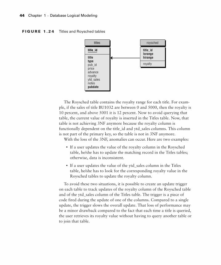
Adding a redundant column is probably the most straightforward andlogical denormalization technique. It consists of copying a column in achild table to a parent table. It generally violates the Third Normal Form,but it does help some queries to avoid a join. In the Pubs database,consider the Titles and Roysched tables (Figure 1.24).
The Denormalization Process 43
2942C01.qxd 11/5/04 1:28 PM Page 43
F I G U R E 1 . 2 4 Titles and Roysched tables
The Roysched table contains the royalty range for each title. For exam-ple, if the sales of title BU1032 are between 0 and 5000, then the royalty is10 percent, and above 5001 it is 12 percent. Now to avoid querying thattable, the current value of royalty is inserted in the Titles table. Now, thattable is not achieving 3NF anymore because the royalty column isfunctionally dependent on the title_id and ytd_sales columns. This columnis not part of the primary key, so the table is not in 3NF anymore.
With the loss of the 3NF, anomalies can occur. Here are two examples:
■ If a user updates the value of the royalty column in the Royschedtable, he/she has to update the matching record in the Titles tables;otherwise, data is inconsistent.
■ If a user updates the value of the ytd_sales column in the Titlestable, he/she has to look for the corresponding royalty value in theRoysched tables to update the royalty column.
To avoid these two situations, it is possible to create an update triggeron each table to track updates of the royalty column of the Roysched tableand of the ytd_sales column of the Titles table. The trigger is a piece ofcode fired during the update of one of the columns. Compared to a singleupdate, the trigger slows the overall update. That loss of performance maybe a minor drawback compared to the fact that each time a title is queried,the user retrieves its royalty value without having to query another table orto join that table.
Triggers are discussed in Chapter 6: Creating and Maintaining DatabaseObjects.
Adding a Derived Column
Another useful technique of denormalization is the use of derived columns.A derived column is a column whose values are calculated from the valuesof one or many other columns of the same table or other tables. Addingsuch a column generally violates the 3NF, since this column is functionallydependent on non-key columns.
The simplest example is the computed column: In a Sales table, youstore the amount, the sales tax, and the net price, calculated from theamount and the sales tax.
The Titles and Sales table in Figure 1.25 illustrates a more complicatedexample.
F I G U R E 1 . 2 5 Titles and Sales table
Each time you wish to know the year-to-date sales of a given book, youneed to query the Sales table and total the values of the qty column forthat book. It may be a long-running query if the sales table is big. To avoidquerying that table and totaling the values, the architect introduced theytd_sales column in the Titles table. Now each time you query the sales ofa given book, you just have to query the Titles column. Of course, as for
the redundant column, the value of that column needs to be maintaineddynamically to be consistent and accurate.
You can add triggers to the Sales table to update the ytd_sales columnof the Titles table each time a sales record is inserted, deleted, or updated.This trigger will lower the performance and inserts, deletes, and updates.But again, the performance gain of the data retrieval must outweigh theperformance loss of the insert, delete, and update operations.
Partitioning Tables
Partitioning a table is not really a denormalizing technique, but it is worthmentioning because it can address particular performance issues. There aretwo ways to partition a table: horizontally or vertically.
Vertical Partitioning
Vertical partitioning consists of cutting the table in two or more tables bymoving entire columns. Consider the example illustrated in Figure 1.26.
F I G U R E 1 . 2 6 Vertical partitioning
The Publishers table has been split into two tables. One (Publishers)contains all the “basic” information, and the other (Pub_info) contains thelogo and the pr_info field. This split has been realized for two reasons:
■ There is not a logo and a description for every publisher, so itmakes more sense to split mandatory information from optionalinformation.
■ The fields in the Pub_info table are large binary objects (BLOB), andthe architect may want to store them in another disk or “tablespace.”
Publishers pub_info
has1
pub_id pub_id
logopr_info
pub_namecitystatecountry
46 Chapter 1 ■ Database Logical Modeling
2942C01.qxd 11/5/04 1:28 PM Page 46
SQL Server 2000 allows you to store text and image columns on anotherfilegroup thanks to the clause TEXTIMAGE_ON of the CREATE TABLE state-ment. See Chapter 2: Database Physical Modeling, for more information onthe CREATE TABLE statement.
Another interesting point concerning vertical partitioning is the tablewidth and the number of records per page. In SQL Server 2000, an 8Kpage contains a certain number of records. The wider the table, the fewerthe records per page. The cache hit ratio may increase, the number of I/Oper operation may lower, and the SQL Server cache may be well used.
In splitting a table for performance purposes, you should consider keep-ing the columns that are accessed more frequently in the “master” tableand moving the other columns to one or more “slave” tables. Then, a one-to-one relationship between the master and each slave table guarantees thereferential integrity.
Horizontal Partitioning
Another classic way of partitioning a table consists of moving a certainnumber of rows to one or many other tables. This is done duringarchiving, for example. If you consider a Sales table, you can imagine thatevery July the sales from July of last year to June of this year are archived.This technique is fine to keep small tables for the transactional system,while still allowing access to the archived data.
A view can be used to simulate a full view of archived and live data. Withthe new feature of partitioned view of SQL Server 2000, this techniquebecomes very interesting to achieve scaling out.
Other examples can be found in real-world applications, like splittingcustomers from prospects, active customers from customers who have notplaced an order for more than 12 months, and so on.
The Denormalization Process 47
2942C01.qxd 11/5/04 1:28 PM Page 47
Summary
This chapter is the only entirely theoretical one of the book. It maybe hard to remember all the terms and concepts we have learned here. Butit’s the kind of information you will use all your database life long, becauseyou cannot create a good database application without keeping these con-cepts in mind.
In this chapter, we covered the following:
■ Designing a database system
■ The Entity/Relationship model
■ The relational model and the normalization process
■ The denormalization process
Exam Essentials
Know what makes a good database design. In the exam, you will bejudged on your real-world knowledge. Knowing what makes a gooddatabase design will enable you to focus on the technical questions andtricks.
Identify entities and attributes. The basis of ER modeling is the identi-fication of entities and attributes. Having a thorough knowledge ofmodeling will help you criticize the way a database is designed and willhelp you to create a good design.
Identify the types of relationships. Even if one-to-one or one-to-manyrelationships are obvious, you should know how to manage every typeof relationship, even many-to-many.
Know how to define key attributes. Candidate keys, primary keys,and alternate keys are the identification keys of your entities. Foreignkeys are the basis of relationships. Defining them will allow you toenforce entity and referential integrity.
48 Chapter 1 ■ Database Logical Modeling
2942C01.qxd 11/5/04 1:28 PM Page 48
Identify precisely all the integrity types. Integrity is the source of cor-rect data. Know the four types of integrity, what they are used for, andhow they can be enforced to design a precise and optimal ER model.
Know how to normalize and denormalize an ER model. You shouldhave no problems with normal forms, at least up to the third. Denor-malization techniques are commonly used and can appear in the exam.
Key Terms
Before you take the exam, be certain you are familiar with the fol-lowing terms:
alternate keys character attributesartificial key Integrityattribute key attributebinary attributes logical designbusiness rules logical modelcandidate key many-to-many relationshipcardinality non-key attributeconceptual design normal formdenormalization Normal form theoryderived column normalization processdeterminant Numeric attributesdirection one-to-many relationshipdomain one-to-one relationshipdomain integrity physical modelenterprise integrity primary keyentity referential integrityentity integrity Relational Database Manage-ER model ment Systems (RDBMS)existence relational modelfixed point relational tablefloating point relationshipforeign key special attributesfull functional dependency transitive dependency
Key Terms 49
2942C01.qxd 11/5/04 1:28 PM Page 49
Review Questions
1. You are a developer for World Wide Importers. You are designingthe new shipment tracking system. You print your ER model toshow some selected users during the next phasing meeting (seegraphic).
50 Chapter 1 ■ Database Logical Modeling
2942C01.qxd 11/5/04 1:28 PM Page 50
What should you add to your model to ensure a useful meeting withyour end-users?
A. Attributes
B. Entities
C. Datatypes
D. Relationships
2. Build a list: As a database consultant, you have been asked tooptimize a database model designed by the IT department of aninsurance company. The model comprises just entities and attributes.You should follow a certain number of steps before producing anoptimized ready-to-implement model. What is the proper sequenceof steps to produce this model? Some elements may not be part ofthe sequence.
Define primary keys
Denormalize the model
Define attributes
Normalize the model
Define alternate keys
Define entities
Define relationships
3. You are a developer for World Wide Importers. One developer ofyour team is working on the Products entity. Each product isimported by one supplier only. You need to record information onevery product and on every supplier. Your developer shows you thestructure of the table he designed and a data sample (see graphics onnext page).
Review Questions 51
2942C01.qxd 11/5/04 1:28 PM Page 51
As a matter of fact, you discover that the table needs a little extrawork. In which normal form is it?
A. First
B. Second
C. Third
D. Boyce-Codd
4. You are developing a new customer care system for an insurancecompany. Every customer will be assigned a unique customer IDmade of a combination of 7 characters and 8 figures. You expect tohave over one million customers, each signing an average of 2.5policies. Furthermore, it is important to track every customer’squestions and complaints. You expect over 10 questions andcomplaints per customer. You want to minimize space used in yourdatabase. What primary key are you going to define for thecustomers table to minimize space and programming tasks?
A. An integer column, defined with an auto-numbering property
B. The customer ID
52 Chapter 1 ■ Database Logical Modeling
2942C01.qxd 11/5/04 1:28 PM Page 52
C. A unique identifier column, designed to generate a new globallyunique ID for every row
D. A big integer column, defined with an auto-numbering property
5. You are a database developer for a banking corporation. Recently,one of the counter clerks “lost” a customer. This customer went tothe bank for a deposit, but the counter clerk could not find her byher customer ID. In fact, after a few minutes’ search, he found her,but with a wrong ID. After looking at the audit tables, it seemedanother counter clerk accidentally modified the customer ID. Youneed to forbid the modification of the primary key to avoid anyother “loss” like this. In SQL Server 2000, what is the fastest way toimplement this feature, without modifying the existing front-endapplication?
A. Alter the table to enable the CHECK PRIMARY KEY option.
B. Alter the table to disable the MODIFY PRIMARY KEY option.
C. Add an AFTER UPDATE trigger to the table that rolls back thetransaction in case of modification of the primary key value.
D. It is not possible to implement this feature in SQL Server.
6. The database application you developed last year for the insurancecompany you are working with was performing well, until lastmonth when some users started to complain about some long-running queries. Last month your company acquired anotherinsurance company and inserted all its existing customers andpolicies into the database, increasing the volume of data by amagnitude of 3. You have been asked to find the cheapest solutionto this performance problem before the end of the week. Afterhaving analyzed what was happening, you have observed that only10 percent of the data is used 90 percent of the time. In fact, dataolder than 2 years are selected only in 0.5 percent of the time. Whatis the solution you are going to implement?
A. Buy a new RAID 5 subsystem and spread the data all over thedisks.
Review Questions 53
2942C01.qxd 11/5/04 1:28 PM Page 53
B. Change the server to a new 4-way machine.
C. It is not possible to enhance performance before the end of theweek. You need more time.
D. Split the data horizontally and store the archive table on anotherdisk.
7. The database application you developed last year for the regionalbank you are working with was performing well, until last monthwhen some users started to complain about some long-runningqueries. Last month your company acquired another bank andinserted all its existing customers and accounts into the database,increasing the volume of data by a magnitude of 5. You have beenasked to find the cheapest solution to this performance problembefore the end of the week. After having analyzed what washappening, you have observed that each time an employee wasgaining access to a customer record, the system was calculating theamount of money of his account based on all the money transferredsince the beginning of the year. What is the solution you are going toimplement to hasten the access to the customer record?
A. Create a stored procedure that calculates the amount on the fly.
B. Denormalize the customer table to include the calculated amountvalue, updated through a batch that runs every night.
C. Index the transfer table to fasten the join with the customerstable.
D. Create a temporary table in tempdb that stores the account’samount and query this table each time a customer is queried.
8. You are helping your town library develop their new computersystem to track members, books, and borrowed books. The managerof the library is a computer addict but knows little of ER modeling.She designed a Member table to store every member, assigning eacha unique ID. She designed a Book table to store every book of thelibrary, and a Borrowed table to assign every borrowed book tomembers. Each member can only borrow three books at a time, can
54 Chapter 1 ■ Database Logical Modeling
2942C01.qxd 11/5/04 1:28 PM Page 54
keep them up to four weeks and must bring them back at the sametime. The proposed design is illustrated in the following graphic:
What level of normal form is reached by this model?
A. None
B. 1NF
C. 2NF
D. 3NF
9. You are a SQL Server developer for Northwind Traders. Your userscomplain about performance of the application when they query theorder amount per employee name and per customer name. After aquick investigation, you discover that this is due to the number oftables joined to calculate the amount. Your logical design isrepresented in the graphic on the next page.
Review Questions 55
2942C01.qxd 11/5/04 1:28 PM Page 55
What can you do to optimize this query?
A. Create a new denormalized table containing the employee name,the customer name, and the amount ordered, and create thenecessary trigger to maintain this table.
B. Create a stored procedure that performs the needed calculation.
C. Create new indexes on the Order Details table.
D. Create a view on the four tables.
10. You are a database developer for the local university. You need todefine a relationship between the students and the courses, knowinga student can attend many courses and one course can be attendedby many students. You have the two entities illustrated in thefollowing graphic:
Students Courses
StudentIDFirstNameLastName
CourseIDCourseName
56 Chapter 1 ■ Database Logical Modeling
2942C01.qxd 11/5/04 1:28 PM Page 56
How can you implement this many-to-many relationship?
A. Insert a StudentID attribute in the Courses table and a CourseIDcolumn in the Students table.
B. Create a new entity called StudentsCourses containing at leasttwo attributes, StudentID and CourseID, forming the primarykey.
C. Insert a StudentID attribute in the Course table.
D. Insert a CourseID attribute in the Students table.
11. One of the developers on your team asked you about a problem hecould not address. He needs to represent a hierarchy in the new HRdatabase. Every employee reports to a manager. Managers canreport to another manager and so on, up to the CEO. He explains toyou that there are five hierarchical levels in the company, so heintends to create five entities representing every level. You think thiscan lead to many problems, the first being the case of a promotion.A promoted employee has to be moved from one level to an upperlevel, and that could lead to consistency issues. What is the bestsolution, using the ER model, to address such a hierarchy?
A. Use two tables, one containing the employee information andone the hierarchy information.
B. It is impossible to address this problem in a relational database.
C. Keep a table for every hierarchical level and develop a series ofstored procedures to manage inserts, deletes, and updates.
D. Insert a ReportsTo column in the Employees table and create arecursive relationship.
12. As an independent SQL Server expert, you have been chosen toexplain the ER modeling that the developers will to use to model theneeded data and business processes to users of the future loyaltymanagement system. You decide to define the basic objects of theER model. What are they? (Chose three.)
A. Entity
B. Relationship
C. Datatype
Review Questions 57
2942C01.qxd 11/5/04 1:28 PM Page 57
D. Attribute
E. Property
F. Columns
13. You are a SQL Server database developer for Northwind Traders.You designed the Products, Categories, and Suppliers tableillustrated in the graphic below.
What is the level of normalization of your model?
A. 1NF
B. 2NF
C. 3NF
D. BCNF
14. You are designing a new procurement database for a regional bank.While defining the suppliers and orders relationship, you are facedwith the choice of what has to be done when a supplier is deletedfrom the database. You must propose all the SQL Server possibledeclarative choices to your customer. What are they? (Choose allthat apply.)
A. Restrict: You cannot delete a supplier if it is linked with existingorders.
B. No Effect: You can delete a supplier even if it is linked withexisting orders.
58 Chapter 1 ■ Database Logical Modeling
2942C01.qxd 11/5/04 1:28 PM Page 58
C. Default: All foreign keys are defined to a default value if thematching primary key is deleted.
D. Cascade: Every order is deleted if the linked supplier is deleted.
15. You are a database developer for an insurance company. Everyinsurance policy is managed by one and only one product manager.One product manager can manage many policies. How can yourepresent that information in the database?
A. Include the manager ID in the Policies entity.
B. Include the policy ID in the Managers entity.
C. Create a relationship entity formed by the policy ID and themanager ID.
D. Include the manager ID in the Policies entity and the policy ID inthe Managers entity.
Answers to Review Questions
1. D. Attributes and entities are represented in the diagram. End-usersdo not need to be know about datatypes, but they do need to knowabout relationships to fully understand the links between entities.
2.
Defining primary keys first allows you to enforce entity integrityand prepare the normalization process that is based on functionaldependency to the primary key. Normalizing the database leadsnaturally to the definition of relationships. You will then have a3NF model that you will only need to denormalize if needed.
Define primary keys
Normalize the model
Define relationships
Denormalize the model
Answers to Review Questions 59
2942C01.qxd 11/5/04 1:28 PM Page 59
3. B. Some non-key attributes depend on other non-key attributes. Forexample, Country depends on the supplier name and product ID.This is a transitive dependency: if you have the product ID, you canfind the supplier name, and once you get the supplier name, youcan find the supplier country. So, if you know the product ID, youknow the supplier country. Country is not functionally dependentonly on the primary key, but also on the Company Name.
4. A. For one million rows, the integer is sufficient (it goes up to morethan 2 billion) and will consume only 4 bytes per row instead of 15for the customer ID, 16 for the unique identifier, and 8 for the biginteger.
5. C. Options A and B do not exist. C is the only way to do it withoutmodifying the programming logic.
6. D. The 3NF seems to be the problem in the sense that there is toomuch data in the table and the machine is probably not suited forthat volume of data. So, the cheapest solution is to split the tablehorizontally and store older data on another disk to minimize thevolume of data in memory.
7. B. This is a classic problem of heavy calculation on a frequentlyaccessed table. The only solution is to denormalize the table with acolumn updated through a batch or a trigger, depending on thefrequency of inserts and deletes.
8. A. The Borrowing table contains a repeating group. To be in FirstNormal Form, the table should only contain one BookID column,not three.
9. A. Creating a new table will give the best results since the infor-mation will be immediately available. However, the informationshould be updated through synchronous or asynchronousmechanisms.
60 Chapter 1 ■ Database Logical Modeling
2942C01.qxd 11/5/04 1:28 PM Page 60
10. B. The only way to implement a many-to-many relationship in ERmodeling is by creating a new entity made of, at least, the primarykeys of the linked entities.
11. D. This is the classical hierarchy problem. In such a case, the onlysolution is a recursive relationship, which handles the hierarchy.
12. A, B, and D. ER stands for Entity-Relationship, and an entity ismade of attributes.
13. B. This is a tricky question. At first sight, the model is in 3NF, butthere is a transitive dependency in the Suppliers table: ContactTitledepends on ContactName and not only on SupplierID. You shouldintroduce a Contacts table to be in 3NF.
14. A, B, and D. This is a tricky one. Options A and D are obvious, butB is possible if you do not enforce the foreign key in the Orderstable. C is only possible through stored procedures or triggers.
15. A. This is a one-to-many relationship. Each policy can have only onemanager ID, so the manager ID must be part of the Policies table.