Introduction to Laser Beam and Spectral Measurement www.cvimellesgriot.com 11.1 Introduction to Laser Beam and Spectral Measurement Introduction to Laser Beam and Spectral Measurement Introduction to Beam Analysis 11.2 Fundamentals of Power and Energy Measurement 11.4 Fundamentals of Beam Positioning 11.12 Fundamentals of Spectral Analysis 11.15 Fundamentals of Beam Profiling and Beam Measurement 11.22 Introduction to Laser Beam and Spectral Measurement 11
Transcript
Introduction to Laser Beam and Spectral M
easurement
www.cvimellesgriot .com
11.1Introduction to Laser Beam and Spectral Measurement
Introduction to Laser Beam and Spectral Measurement
Introduction to Beam Analysis 11.2
Fundamentals of Power and Energy Measurement 11.4
Fundamentals of Beam Positioning 11.12
Fundamentals of Spectral Analysis 11.15
Fundamentals of Beam Profilingand Beam Measurement 11.22
Introduction to Laser Beamand Spectral Measurement 11
It is becoming increasingly important to characterize laser beam parametersfully. The traditional ways of specifying laser beams are necessary, butnot sufficient. It used to be that the measurement of wavelength, power,beam width, and mode structure were sufficient for most applications.But there is a significant trend in the photonics industry toward requiringdiffraction-limited performance from lasers and optical systems in orderto increase the precision and reproducibility with which beams propagate,interact, and can be focused on a target.
CVI Melles Griot provides a complete range of instrumentation to measurenot only the traditional parameters, but also difficult-to-measure para-meters such as beam profile, propagation factor (M2), and beam spectralmeasurements in both wavelength and frequency space. Our instrumentstake full advantage of state-of-the-art transducers and the full computa-tional and graphic-display capabilities of modern personal computers.Thus this range of instruments provides cost-effective solutions to manylaser-beam measurement and characterization needs, both in researchand development laboratories and in manufacturing quality-assurancetest stations.
CVI Melles Griot instrumentation falls into four broad categories: powerand energy measurement, beam-postion measurement, spectral analysis,and beam-intensity profiling.
POWER AND ENERGY MEASUREMENT
One of the most fundamental measurements for a laser is its outputpower and/or energy. CVI Melles Griot offers complete metering systems(detector head and control/display unit) featuring broadband thermopileand pyroelectric thermal detectors, with flat response from 200 nmto 20 mm, as well as several varieties of photodiode (quantum) powerand energy detectors.
Introduction to Beam Analysis
For observing modulated continuous wave (cw) beams, determining pulseshapes, and measuring high-speed noise, we offer a range of high-sen-sitivity silicon detectors and matching current amplifiers, together witha modular mounting system and a full range of accessories, includingintegrating spheres.
BEAM-POSITION MEASUREMENT
An unfortunate characteristic of a laser beam is that it changes positionas a function of time, age, and atmospheric conditions. In most cases,the movement is only a fraction of a diameter, but in a long-path opticaltrain, even this movement can cause problems. CVI Melles Griot offers
Intr
oduc
tion
to L
aser
Bea
m a
nd S
pect
ral M
easu
rem
ent
www.cvimellesgriot .com
Introduction to Laser Beam and Spectral Measurement
Introduction to Laser Beam and Spectral Measurement11.2
Beam Alignment and Positioning MeasurementPower and Energy Meters
four types of systems for measuring beam position and drift: a quadrantdetector system for exact centering and alignment, a lateral-effectsdetector system for measuring larger-scale movement, a dual-detectoralignment system that measures both beam position and angulardeviation (critical for aligning long-path transfer systems and articulatedarms), and a camera-based system for the simultaneous measurementof multiple beams.
SPECTRAL ANALYSIS
A fundamental property of a laser is its wavelength. For many lasers,particularly those operating on narrow atomic transitions, the wave-lengths are well defined, at least down to a tenth of a nanometer or less(e.g., the red helium neon lasers output is always 632.8 nm). For broadbandlasers, however, this is not the case. A typical dye or titanium-sapphire lasercan be continuously tuned over 50 nm or more; the output of a semi-conductor diode laser can drift over several nanometers as a function oftemperature; some diode-pumped solid-state lasers can be tuned overmany nanometers. To measure the fundamental wavelength of a laser,CVI Melles Griot now offers an inexpensive laboratory wavemeter withan accuracy of 0.5 nm. To measure the fine modal structure of the laserbeam, we offer two confocal Fabry-Perot optical spectrum analyzers withfree spectral ranges (FSRs) of 1.5 GHz and 300 MHz.
In addition to the instruments mentioned above, CVI Melles Griot nowoffers a variety of Czerny-Turner spectrometers and a spectrophotometerfor measuring the spectral content of incoherent sources, as well as a lineof spectral-line and illumination sources.
BEAM INTENSITY PROFILERS
For a circular Gaussian beam, knowing the beam-waist diameter and thefar-field divergence is sufficient to characterize completely the propagationof that beam through an optical system. Unfortunately, many real laserbeams are neither circular nor near-Gaussian. There may be a contributionfrom higher-order transverse modes; there may be truncation (clipping)or other distortions introduced by lenses, apertures, or other system optics;and the beam itself may be rectangular, elliptical, or completely irregular.Even for a well-behaved near-Gaussian laser beam it is not safe to assumethat the divergence and beam-diameter specification indicated on thespecification sheet are sufficient to understand the propagation char-acteristics, since the beam waist is rarely located right at the laser, and,in the near field, divergence is much less than in the far field.
CVI Melles Griot offers the most complete line of beam-intensity profilersin the industry, including pinhole, slit, and knife-edge beam scanners,camera-based profilometers for measuring pulsed and cw sources, and M2
meters for determining beam propagation characteristics.
Introduction to Laser Beam and Spectral M
easurement
www.cvimellesgriot .com
11.3Introduction to Laser Beam and Spectral Measurement
Introduction to Laser Beam and Spectral Measurement
Power and energy detectors can be grouped into two broad categories:thermal detectors and quantum detectors. Thermal detectors simply absorbthe incident radiation, increasing the detecting element’s temperature untilthe combined effects of conduction and thermal radiation from the detec-tor are in equilibrium with the energy being absorbed by the detector. Thetwo main types of thermal detectors are thermopiles, used primarily tomeasure the power of cw laser beams, and pyroelectric detectors, usedto measure the energy in a laser pulse. Because thermal detectors measureonly the heat generated in the detector, they are extremely broadband,typically with a flat spectral response from 200 nm to 20 mm and beyond.
Quantum detectors operate on a completely different principle. Thedetector is a semiconductor, and the incident radiation excites electronsfrom the semiconductor’s valence band into the conduction band, generatinga current that is proportional to the number of photons in the incident radi-ation. The gap between the two bands is well defined, and only photons withsufficient energy will be able to move an electron from the valence band tothe conduction band. The critical energy lc is given by
where h is Planck’s constant, c is the speed of light in the semiconductor,and Eg is the energy gap. There are two basic types of quantum detectors:photoconductors, used primarily for measurements in the near infrared(to 5 mm), and photodiodes, used primarily for visible and ultravioletwavelengths. The sensitivity of quantum detectors is very high, allowingmeasurements in the picowatt range, and their response time can be much,much faster than that of thermal detectors. On the other hand, their wave-length sensitivity is very nonlinear, their effective wavelength range is muchnarrower, and they are easily damaged by higher power laser beams.
THERMOPILE DETECTORS
A thermopile detector consists of two sets of thermocouples connectedin series (see figure 11.1). One set of thermocouples is attached to anabsorbing disc (the detector) and the other set is attached to the case(ambient temperature). As incident radiation is absorbed by the disc, thedisc’s temperature rises, generating a voltage that is directly proportionalto the difference in temperature between the disc and the case. Thereadout unit then interprets the voltage measurement and presents theinformation in units of watts (power) or joules (energy).
The detector disc is typically made from graphite or aluminum with a durable,black, absorbing finish. The responsivity of the detector primarily dependsupon the thermal mass of the detector disc and the thermocouples mountedto it. The energy is absorbed at the surface and must have time to spreadthrough the detector and bring the disc to a uniform temperature. For largerdetectors, used primarily for high-power lasers, this can take several seconds;for smaller detectors, a fraction of a second is typical. To counteract this slowresponse time, manufacturers often incorporate circuitry in the readoutelectronics that analyzes the slope of the temperature rise and anticipates
Fundamentals of Powerand Energy Measurement
the equilibrium point. Because of the slow response, thermopile detectorsare used primarily for measuring cw output power and average power forpulsed lasers. Peak pulse power and pulse energy measurements are veryquestionable at rates above a few pulses per second.
PYROELECTRIC DETECTORS
Pyroelectricity and piezoelectricity are closely related. In fact, most piezo-electric crystals also exhibit pyroelectricity. When a pyroelectric crystal is heatedor cooled, the stress generated by expansion or contraction generates avoltage across the crystal which is proportional to the rate at which theenergy is being absorbed. Either this voltage, or the surface charge on thecrystal, can then be measured by a readout unit and converted to watts(peak power) or joules (pulse energy). Unlike a thermopile detector, atthermal equilibrium the voltage across the crystal and the surface chargedissipate, making these detectors unsuitable for cw applications. Detectorsystems that read the voltage across the crystal are limited to relatively lowpulse repetition rates (10’s of Hz) because the heat must permeate throughthe thermal mass of the crystal. Detector systems that measure the surfacecharge can operate at high pulse rates (>1 kHz) because only the temper-ature of the crystal at the surface is important; however, at low repetitionrates (<10 Hz) the response falls off markedly.
PHOTOCONDUCTORS
Photoconductive detectors are heavily doped semiconductors that have afinite electrical conductivity that increases with temperature. They are usedprimarily for infrared detection. Typically, the detectors are biased at a fixedvoltage, and the current flowing through the detector provides the signal.One problem with photoconductive detectors is that a small change inambient temperature may significantly increase the dark current (thecurrent flowing through the device when no light is present), swamping thesignal. Consequently, either the temperature of the detector must bestabilized or some sort of phase-sensitive detection scheme must be used.
Intr
oduc
tion
to L
aser
Bea
m a
nd S
pect
ral M
easu
rem
ent
www.cvimellesgriot .com
Introduction to Laser Beam and Spectral Measurement
Introduction to Laser Beam and Spectral Measurement11.4
Photodiodes have complex electrical characteristics and can best beunderstood using the concept of the equivalent circuit—a circuit of indi-vidual components (resitors, capacitors, etc.) whose collective (lump-sum)behavior models that of the actual photodiode.
The ideal photodiode can be considered as a current source parallel to asemiconductor diode. The current source corresponds to the current flowcaused by the light-generated drift current, while the diode represents thebehavior of the junction in the absence of incident light.
An actual photodiode is represented by the equivalent circuit shown infigure 11.2.
In addition to a current source in parallel with a semiconductor diode, anonconductive layer devoid of carriers (depletion layer) is sandwichedbetween two conductive layers. This is a classic parallel-plate capacitor,which can support charge separation only in one direction. The effectivecapacitance, termed the junction capacitance (Cj), is represented in theequivalent circuit by a capacitor in parallel with the other components. Thephotodiode junction also has finite shunt resistance (Rsh). Ancillary parts ofthe diode (neutral layers, electrical contacts) also give rise to a resistance,usually much smaller than the shunt resistance. This resistance acts betweenthe diode junction and the signal sensing circuit and is therefore termedthe series resistance (Rs). The series resistance can usually be assumed toequal zero for modeling and computational purposes.
Photodiode Operation
A photodiode behaves like a photocontrolled current source in parallel witha semiconductor diode and is governed by the standard diode equation:
whereI is the total device currentIphoto is the photocurrentIdk is the dark currentV0 is the voltage across the diode junctionq is the charge of an electronk is Boltzmann’s constantT is the temperature in degrees Kelvin.
The I-V (current-voltage) relationship of this equation is shown in figure11.3. Two significant features to note from both the curve and theequation are that the photogenerated current ( Iphoto ) is additive tothe diode current, and the dark current is merely the diode’s reverseleakage current. Finally, the detector shunt resistance is the slope of theI-V curve (dV/dI ) evaluated at V=0.
Quantum Efficiency
Photodiodes are quantum devices. Each incoming photon will generateeither one or zero units of electron charge which will contribute to thephotocurrent. The probability of generating a charge is termed thequantum efficiency (h). Quantum efficiency mainly depends on howefficiently charge carriers are swept across the junction. The overallquantum efficiency of the photodiode is often referred to as externalquantum efficiency.
Introduction to Laser Beam and Spectral M
easurement
www.cvimellesgriot .com
11.5Introduction to Laser Beam and Spectral Measurement
Introduction to Laser Beam and Spectral Measurement
Pincident light
sensing circuit(resistive load or amplifier)
Iphotodiode
C j
Rsh
Rs
Figure 11.2 Lumped-sum equivalent-circuit modelof a photodiode
I
Idk
P1
P2
V
P
V
+
-
bre
akd
ow
n r
egio
n
i
P2 >P1
dVdI
= Rsh
Figure 11.3 The II-VV relationship of a photodiode
Responsivity (ℜ) quantifies the photoelectric gain of a detector. Photodioderesponsivity is the ratio of the photocurrent (across an effective zeroresistance) generated for each watt of incident light power, expressed asamps/watt (A/W). Responsivity depends directly on the quantumefficiency. The maximum theoretical achievable responsivity correspondsto detection of every incident photon (unit quantum efficiency). Theenergy carried by each photon depends on its frequency according tothe equation E = hv, where v is the photon frequency (inversely propor-tional to l, its wavelength) and h is Planck’s constant. Therefore,expressing the responsivity in A/W (as opposed to A/photon) gives thisparameter an inherent wavelength dependency:
wherec is the speed of lightq is the charge of an electronl is the wavelength in meters of the photons being detected.
Responsivity has an additional wavelength dependence arising from thevariation of quantum efficiency with wavelength. At wavelengths wheresilicon does not absorb strongly, photons may penetrate more deeply intothe device (or pass through it), leading to minority carrier generation tooremote from the junction to be detected (i.e., lower quantum efficiency).The typical shape of the silicon photodiode responsivity spectral curve isdetermined by the absorption spectrum of silicon (see figure 11.4). Photo-diode responsivity is usually specified at a single wavelength unless acomplete wavelength calibration is performed.
As an example, a silicon photodiode normally will have a high quantumefficiency for light at 800 nm. Assuming a typical hof 0.8 at this wavelength,this leads to a responsivity of 0.52 A/W. At 400 nm a typical h would beonly 0.15, which leads to a responsivity of 0.1 A/W.
Responsivity alone is a weak figure of merit because it specifies only the gainof a photodiode, not its associated noise. Signal-to-noise ratio represents theultimate figure of merit, as discussed later.
Linearity of Response
In many applications it is necessary for the responsivity to remain constantover a wide range of incident light power. Most P-N silicon photodiodesare linear (better than 1%) over seven or eight orders of magnitude. How-ever, when the number of incident photons becomes comparable to thenumber of electron-hole locations in the active region, the device saturates,resulting in a loss of linearity.
In the case of the CVI Melles Griot silicon photodiodes, the photocurrentwill have a linear relationship to the incident intensity, providing the currentdensity is less than 5#1045 A/mm2. The maximum allowable radiantintensity is therefore given by:
where ℜ is the responsivity at the detection wavelength in A/W.
It is important to understand this limitation when using a photodiode todetect laser radiation. The raw output beam from a 1-mW HeNe laser hasmore than twice the intensity (W/mm2) necessary to saturate a typicalsilicon photodiode.
System linearity is also affected by the sensing circuit. Incident light on thephotodiode’s active area produces a photocurrent which is usually mea-sured by the amount of voltage dropped across an external resistance ofknown size. As the resultant voltage in the sensing circuit increases, thephotodiode becomes forward biased, leading to nonlinear response.
Junction Capacitance
When designing a sensing circuit to maximize the speed or linearity ofresponse, one must know two important electrical characteristics of aphotodiode: the junction capacitance (Cj) and the shunt resistance (Rsh).Without these, the RC time constant of the complete operating circuitcannot be calculated.
The parallel-plate capacitance across the depletion region gives rise toa junction capacitance which increases with the area of the junction.Since increasing capacitance in a circuit slows its speed of response, pho-todiodes with smaller active areas are inherently capable of faster responsethan those with larger active areas. The junction capacitance is a functionof the thickness of the depletion layer, which varies with applied bias
Intr
oduc
tion
to L
aser
Bea
m a
nd S
pect
ral M
easu
rem
ent
www.cvimellesgriot .com
Introduction to Laser Beam and Spectral Measurement
Introduction to Laser Beam and Spectral Measurement11.6
400 600 800 1000
0.2
0.4
0.6
0.8
WAVELENGTH IN NANOMETERS
1200
100%QUANTUM EFFICIENCY
RES
PON
SIV
ITY
IN A
MPS
/WA
TTS
Figure 11.4 Typical responsivity of a CVI Melles Griotsilicon photodiode
Care should be taken to limit the current through the diode in the reversebias region so that the resultant power dissipated does not exceed 200 mW.
Noise-Equivalent Power and Signal-to-Noise Ratio
Noise-equivalent power (NEP) is the incident light level impinging ona photodiode, which produces a photocurrent equal to the noise level. Itis usually regarded as the most significant figure of merit for a photode-tector. The NEP is a function of the photodiode’s responsivity, the noise ofthe photodiode and the associated sensing circuit, and the frequencybandwidth over which the noise is measured. In systems applications, thesignal-to-noise Ratio (SNR) may be computed by taking the ratio of theincident optical power to the photodiode NEP.
In general terms, NEP is defined as follows:
where ℜ is in A/W.
The rms noise current (irms) is the total integrated noise over the frequencies of interest (f1 to f2), defined as follows:
(see figure 11.5). Therefore, it is common to specify the junction capac-itance at zero external bias. This topic is covered in the discussion onreverse bias operation of photodiodes.
Detector Angular Response
The photocurrent generated from a photodiode is essentially indepen-dent of angle of incidence of the incoming radiation when the angle ofincidence is less than 30 degrees. Typically, a variation in photocurrentof 1 to 2 percent can be expected, provided the detector’s active areais underfilled, i.e., the incoming radiation does not completely cover thedevice’s entire active area. (This condition assumes the photodiode’sabsorption layer thickness approximately equals the depletion layerthickness in the photodiode junction.)
In circumstances where the photodiode is immersed in a collimated beamof incident light, the device’s responsivity will fall off with the cosine ofthe angle of incidence as follows:
ℜv=ℜcosv
where ℜ is the photodiode responsivity at normal incidence.
Photodiode Speed of Response
Inherent limitations of photodiode response are due to structure andspecific junction design, the presence of an externally applied bias, andthe wavelength of incoming radiation. The inherent time constant of aphotodiode causes a delay in generated photo current (t). For CVI MellesGriot silicon photodiodes, this time constant is typically 7 to 15 nsec. Thephotodiode speed of response for various load conditions is discussed inthe section on sensing circuits for photodiodes.
Dark Current
The P-N junction of a photodiode does not present an infinite resistanceto reverse current flow. Consequently, when a reverse bias is applied to aphotodiode, a small current (Idk) flows even in the absence of incidentlight, as shown in the I-V curve. This dark current increases slowly withincreasing reverse bias. Dark current approximately doubles every 8°C.
A large dark current is undesirable since it may represent a significantbackground above which the actual photocurrent is measured. Further-more, shot noise associated with the dark current may be significant.
Breakdown Region
There is a maximum reverse bias voltage that can be applied to a photo-diode, called the reverse breakdown voltage. At this point, the device isno longer useful as a photodetector and can sustain permanent damage.
Introduction to Laser Beam and Spectral M
easurement
www.cvimellesgriot .com
11.7Introduction to Laser Beam and Spectral Measurement
Introduction to Laser Beam and Spectral Measurement
200
600
1000
1400
1800
2200
0 2 4 6 8 10
JUN
CTI
ON
CA
PAC
ITA
NC
E IN
pf/
cm2
REVERSE BIAS IN VOLTS
Figure 11.5 Typical relationship of a silicon photodiode’sjunction capacitance and applied bias
The lower detection limit for any photodetector is ultimately determined bythe device’s noise characteristics. There are three main contributions to pho-todiode noise: Johnson noise, shot noise, and 1/f noise (see figure 11.6.)
Johnson Noise
The statistical fluctuation in the thermal electron-hole pair generation iscalled thermal noise or Johnson noise (IRsh). Johnson noise is broadband“white” noise and is expressed as noise per unit bandwidth. The expressionfor Johnson noise of the photodiode shunt resistance is as follows:
wherek is Boltzmann’s constantT is the absolute temperature in degrees KelvinRsh is the shunt resistance in ohms.
As seen from the above formula, Johnson noise increases in proportion tothe square root of the temperature.
Intr
oduc
tion
to L
aser
Bea
m a
nd S
pect
ral M
easu
rem
ent
C j R sh√2q(Iphoto+Idk) √4kT
Rsh
Io( )1s
a
Inoise
C s I amp
vn
R TIA
Vout
C TIA
- G(s)=∞+
√4kT R sh
Vn(s)shotnoise
Johnsonnoise
1/fnoise
Figure 11.6 System noise model of a detector and transimpedance-amplifier setup
A/ HzIkT
RR
shsh
=4
(11.7)
If the bandwidth over which the noise is integrated is 1 Hz at frequencyf, this is referred to as the noise spectral density at frequency f, with unitsof W/Hz1/2. Since the rms noise is highly dependent upon system application,it is common for noise sources to be specified in terms of noise spectraldensity at a specific frequency. Since the noise will vary with wavelength,frequency, and temperature, all pertinent parameters must be specified whendiscussing NEP. The nomenclature NEP (l, f, T) delineates the specificationat wavelength l, frequency f, and temperature T.
www.cvimellesgriot .com
Introduction to Laser Beam and Spectral Measurement
Introduction to Laser Beam and Spectral Measurement11.8
Shot Noise
Shot noise (Ish) is the statistical noise associated with the photocurrentand dark current (if present). Since shot noise is also broadband, it isexpressed as noise per unit bandwidth:
whereq is the charge carried by an electronIphoto is the photocurrentIdk is the dark current.
1/ff Noise
The mechanism for 1/f noise is not particularly well understood. Oftenthe characteristics are empirically determined for individual families ofphotodetectors. The 1/f noise is governed by the following characteristics:
whereI0 is typically an inverse function of the active areaa is an empirically derived constant that will vary from 0.25 to
1.0 depending upon the specific construction of thedetector
s is the Laplace operator and = jq.
1/f noise is of concern at frequencies below 100 Hz. For higher frequencyapplications, photodiode performance is limited by other noise sources.1/f noise is zero at zero bias.
Like all semiconductor devices, photodiodes are temperature sensitive.The relative population inversion of electrons and holes in the P- and N-layers of the photodiode is directly influenced by temperature, whichchanges the conductivity and shifts the absorption spectrum. The majorphotodiode parameters that are sensitive to temperature are shunt resis-tance, dark current, and, to a lesser extent, responsivity. Typically, the darkcurrent of a silicon photodiode approximately doubles for each 8°C increaseor decrease in the device temperature. The shunt resistance approximatelydoubles for each 6°C change:
These formulas can be used to calculate the shunt resistance and darkcurrent for any temperature from the specified values, which are usuallyspecified at 25°C.
Increasing the temperature of a semiconductor shifts its absorption spectrumto longer wavelengths by reducing the effective band gap. Fortunately,the absorption spectrum of silicon is quite broad. Consequently, the smalltemperature-induced shifts in the absorption spectrum affect the respon-sivity significantly only at the edges of the spectral responsivity curve, asshown in figure 11.7.
INTEGRATING SPHERES
In many applications of photodetectors, it is necessary to measure theabsolute or relative intensity of a wide-angle beam (divergent source)
or of an inhomogeneous beam much larger than the active area of aphotodetector. Integrating spheres have been used for many years toscramble or average light by multiple diffuse reflections in order toobtain meaningful intensity measurements of these types of sources.
An integrating sphere is a hollow sphere (often aluminum) whose entireinner surface is uniformly coated with a layer of matter which has a highlydiffuse reflectance. When light from a source enters an integrating sphere,it loses all memory of direction and polarization. At the exit port, the lightintensity is uniform and diffuse. Although other methods have beendeveloped to deal with the problems of averaging the intensity from aninhomogeneous source or of a wide-angle beam, an integrating sphere isthe best solution in many applications. In fact, the only real differencesbetween the integrating spheres of today and the spheres of many yearsago are the improved quality and stability of the diffuse reflectance coating.
Lambertian Source — Radiance and Irradiance
The two keys to the operation of an integrating sphere are the coating onthe inside of the sphere and the spherical shape itself. The coated interiorsurface is designed to have a highly diffuse reflectance. When a hypo-thetically perfect diffuse reflector is illuminate with uniform intensity, itbehaves like a perfectly diffuse source—a Lambertian source (i.e., each unitarea reflects light into all available solid angles with equal efficiency).
The complete definition of a Lambertian source is a light source whoseradiance is independent of viewing angle. The most well-known Lam-bertian source is the sun. Radiance is defined as the energy flux perunit projected area per unit solid angle leaving a source or, in general,any reference surface.
Radiance, L, can be expressed as
wheredI is the intensitydQ is the solid angledA is the unit area of the sourcecosv is the viewing or inclination angle.dAcosv is the projected surface area.
To understand the operation of the integrating sphere, consider the lightreflected from a uniformly illuminated small area of the interior surface.This unit area is so small that it can almost be considered a point source.This virtual point source radiates equal intensity in all possible direc-tions. The rest of the sphere can be thought of as a target over which thelight from this source will be distributed. Two counterbalancing factorsensure that this light will be distributed with equal intensity over the entiretarget surface. The important intensity parameter for a target surface isthe incident energy (flux) per unit area. This is termed the irradiance ofthe target surface.
Introduction to Laser Beam and Spectral M
easurement
-5
-4
-3
-2
-1
0
1
2
3
4
5
300 400 500 600 700 800 900 1000 1100
DEV
IATI
ON
OF
SPEC
TRA
L R
ESPO
NSE
IN P
ERC
ENT
WAVELENGTH IN NANOMETERS
15°C
20°C
35°C
30°C
15°C
20°C
30°C
35°C
25°C
Figure 11.7 Temperature dependence of siliconphotodiode responsivity
dk dk
sh sh
I T I T
R T R T
T T
T T
2 18
2 16
2
2
1 2
1 2
( ) = ( )
( ) = ( )
−( )
−( )
LdI
d dA=
Q vcos
(11.10)
(11.11)
(11.12)
www.cvimellesgriot .com
11.9Introduction to Laser Beam and Spectral Measurement
Introduction to Laser Beam and Spectral Measurement
The inverse square law shows that the light flux per unit area will be aminimum at the most distant point on the sphere. However, the irradianceof a unit area of the target surface depends on its angle of inclination tothe source. A large angle of incidence causes the incident flux to be spreadover a large target area (cosine projection). A small angle of incidencepresents the smallest area to any incident light. The same cosine projectionargument applies to the projected area of the source.
The two effects exactly cancel each other so that the light intensity isuniform over the entire area of the sphere. This can be proven by simplegeometry, as shown in figure 11.8.
Consider a small unit area of irradiating surface (dAs), and a small unitarea of target surface (dAt). The intensity of light (irradiance) a on thetarget due to the source dAs is given by:
where L is the source radiance and v is the angle of incidence on dAt. Thed2 term is from the inverse square law, and the cos2v term relates to theeffective (cosine projected) areas of the source and target.
In a real application, when an extended area of the surface is illuminatedwith nonuniform intensity, the directly illuminated spot on the spherecan be considered as a large number of minute Lambertian sources. Inprinciple, therefore, the total flux of the beam entering the sphere isspread (averaged) over the entire surface following only a single reflection.
In order to deliver reliable integration and low throughput loss, the coatingof the integrating sphere must be a very efficient diffuse reflector.Coatings used on integrating spheres provide reflection efficienciesbetween 95 and 99 percent. The reflectance must be high in order tominimize absorption loss caused by multiple reflections, but it must not
reflect light in a specular sense (incidence angle=reflectance angle). Anyspecular component to the reflections off the surface will only helppreserve some memory of original angular and spatial distribution of thelight source. In many applications, it is also necessary that the propertiesof the coating be fairly insensitive to wavelength.
Light is not completely averaged or integrated on the first reflection. Toprevent erroneous readings that are dependent on input angle, thedetector or output port is often shielded with a baffle plate. This small metalplate, also coated with the same diffuse reflectance material, is positionedto preclude any light from the entrance port from reaching the detectorafter only a single reflection.
Performance Characteristics
Two meaningful figures of merit for integrating spheres are throughput andstability. Throughput is defined as the ratio of the flux exiting the sphereto the flux entering the sphere. It is determined by the size of the ports (inputand exit) relative to the sphere area and by the reflectivity.
whereAe is the area of the exit port divided by total sphere areaR is the reflectance of the coatingAp is the total area of all ports divided by total sphere area.
Figure 11.9 shows the reflectance of a typical integrating sphere coating.
Intr
oduc
tion
to L
aser
Bea
m a
nd S
pect
ral M
easu
rem
ent
www.cvimellesgriot .com
Introduction to Laser Beam and Spectral Measurement
Introduction to Laser Beam and Spectral Measurement11.10
100
96
92
88
84
80
76
WAVELENGTH IN NANOMETERS
500 1000 1500 2000 2500
PER
CEN
T R
EFLE
CTA
NC
E
Figure 11.9 Typical reflectance of the integrating spherecoating
Throughput is very dependent on the reflectance of the sphere surface ina nonlinear manner (see figure 11.10).
Stability is the reciprocal of the change in throughput with respect to thechange in reflectivity of the coating. This is an important parameter sincethe reflectivity of the coating may degrade slightly in certain operating envi-ronments over a long period of time, and the reflectivity may be degradednonuniformly over the sphere surface. A small change in the reflectivityof a low-stability sphere will result in a large change in throughput. There-fore, a low-stability sphere is less likely to give an accurate, reproduciblereading than a high-stability sphere.
Stability is related to throughput. A high-throughput sphere is inherentlyless stable than a lower-throughput sphere because of the nonlineardependence of throughput on reflectivity. Stable spheres have reflectivityvalues of 90 percent or less, whereas the low-stability (high-throughput)spheres typically have reflectivities of 97 percent or greater. As an example,a typical low-throughput sphere with a 90 percent reflectivity coatingwill have an inherent stability factor of 0.5, whereas an identical high-throughput sphere with a 99 percent reflectivity coating will have astability factor of 0.05.
Diverse Applications
Integrating spheres are versatile devices which are used in a widerange of applications. This versatility is best illustrated by the examplesoutlined below.
1. Diode Laser and Fiber-Optic Power Measurements. Integratingspheres are ideal for collecting and measuring the highly divergentradiation typical of diode lasers and fiber optics.
2. Intensity Measurements of Extended Sources. Tungstenfilaments, plasma discharges, and other extended sources can be difficultto collimate or efficiently image onto a photodiode of limited area. The largeentrance port of the CVI Melles Griot 13 ISP 005 integrating spherefacilitates coupling in light from extended sources and reduces the needfor a complicated optical system.
3. Absolute Radiometry in Anamorphic Laser Systems. Anintegrating sphere and a large-area detector can accurately measureradiation that is too large to focus onto a detector, or light that is colli-mated in one plane but defocused in the other. A typical application ismeasuring the output from laser line projectors.
4. Measurement of Inhomogeneous Beams. The integratingsphere effectively scrambles the input radiation so that any beam inho-mogeneity and detector nonuniformities do not affect the accuracy ofthe measurement.
5. Creation of a Uniform Intensity Profile. An integrating spherecan be used as a transmissive component to homogenize the spatialintensity profile of a beam from an inhomogeneous source. Uniformillumination is required in applications such as calibrating CCD, CMOS,and photodiode arrays.
Introduction to Laser Beam and Spectral M
easurement
www.cvimellesgriot .com
11.11Introduction to Laser Beam and Spectral Measurement
Introduction to Laser Beam and Spectral Measurement
92
PERCENT REFLECTANCE
1.0
0.5
0.2
0.194 96 98 100
NO
RM
ALI
ZED
TH
RO
UG
HPU
T
Figure 11.10 Normalized throughput variation withreflectance for an integrating sphere
Position-sensitive detectors (PSDs), which detect and record the positionsof incident light beams, find application in the analysis of light sources andindustrial alignment of machinery and targets (when used in conjunctionwith a laser).
Three types of detectors are used for sensing the position of the centroidof a beam in the x-y plane orthogonal to the optic axis: the quadrantdetector, the dual-axis lateral-effect detector, and camera-based detectors(CCD or CMOS). In the case of the quadrant and lateral-effect detectors,four electrodes are attached to a large-area silicon detector, and the fourcurrents generated by photoabsorption are processed with the appropriatealgorithm to give the x and y positions. In the camera-based systems, thebeam position is determined by measuring the intensity of light impingingon each pixel. The quadrant and lateral-effect detectors are discussed inmore detail in the next paragraphs. Camera-based detectors are availablefrom CVI Melles Griot in 1/2-inch (CCD) or 1/3-inch (CMOS) formats.
QUADRANT DETECTORS
The quadrant detector is a uniform disk of silicon with two 10-m-widegaps across the surface. Thus, there are four independent and equal pho-todetectors on the sensing surface. The center of the detector is known veryaccurately since it is the mechanical intersection of the two gap lines anddoes not change with time or temperature. A symmetrical laser or otheroptical beam centered on the detector will generate equal photo currentsfrom each of the four sectors. If the beam moves from the center of thedetector, the currents from the four sectors will change, and the process-ing algorithm will give the x and y displacements relative to the center.
Figure 11.11 illustrates the geometry of the quadrant and lateral-effectdetectors.
In the quandrant detector, the four sectors are represented by lettersA, B, C, and D.
Fundamentals of Beam Positioning
The equations used to describe the x and y displacements of the beam arethe following:
,
where a, b, c, and d are the currents generated by each of the four sectors.There are two significant restrictions on the motion of beams used withquadrant detectors. First, to give x-y data, the beam must always over-lap a portion of all four sectors. Second, there is only meaningful absoluteposition information for small displacements of the beam.
The limits of the 8-mm-clear-aperture CVI Melles Griot quadrant detectorsare illustrated in figure 11.12.
As shown, if a beam is 2 mm in diameter, its center can move a maximumof 1 mm in any direction before it no longer overlaps all the quadrants.Therefore, the center of the beam must remain within a 2-mm-diametercircle, centered on the detector. The motion of beams larger than 4 mmin diameter is restricted by the clear aperture of the detector rather thanthe quadrant overlap requirement. Consequently, the center of a 6-mm-diameter beam can only move 1 mm in any direction without movingoutside the clear aperture and losing part of the signal.
Because most laser beams are circular with Gaussian intensity distributions,the photocurrents become nonlinear for displacements of more thanabout 10 percent of the beam radius. Therefore, absolute x and y coor-dinates become unreliable for beam displacements that are greater thanthe “measuring limit” shown in figure 11.12.
Because of these two restrictions, the quadrant detector is most useful insystems where a beam must be aligned or centered to an optical axis. Itis especially useful where it is necessary to monitor small displacementsover long periods with high stability. In feedback systems, displacementinformation from the quadrant cell is used to realign (null) a laser beam.
Intr
oduc
tion
to L
aser
Bea
m a
nd S
pect
ral M
easu
rem
ent
www.cvimellesgriot .com
Introduction to Laser Beam and Spectral Measurement
Introduction to Laser Beam and Spectral Measurement11.12
A B
C D
quadrantdetector
lateral-effectdetector
electrodes
y
x
Figure 11.11 Physical configuration of the quadrant andlateral-effect detectors
xb d a c
a b c d
ya b c d
a b c d
=+( ) − +( )+ + +
=+( ) − +( )+ + +
POSI
TIO
N
RA
NG
E A
VA
ILA
BLE
(mm
dia
met
er c
ircl
e)
BEAM DIAMETER (mm)
8
6
4
2
8642
measuring limit
centering limit
Figure 11.12 Beam size vs position range for our quad-rant detector
The dual-axis lateral-effect detector uses a doped disk of silicon withfour electrodes connected around its perimeter. Opposite pairs of elec-trodes yield photocurrents that can be processed to give unique valuesof x and y displacement.
Traditionally, the algorithm has been performed with fixed electroniccircuitry, and positions have been accurate to a few percent. The CVIMelles Griot lateral-effect detector employs a software-controlled algo-rithm and stored calibration corrections to linearize the detector responseacross the entire sensing area. Unlike the quadrant detector, the dual-axislateral-effect detector can be used to measure accurately the absoluteposition of a beam over its entire surface.
Figure 11.13 illustrates the position-measurement limit for the 8-mm-diameter CVI Melles Griot dual-axis lateral-effect detector system. Incontrast to a quadrant detector, very small beams can move over theentire 8-mm-diameter surface of the lateral-effect detector. However,because a beam must remain entirely within the area of the detectingsurface, larger beams have a limited range of travel. For example, thecentroid of a 4-mm-diameter beam must remain within a 4-mm-diametercircle centered on the detector.
Because the lateral-effect detector can accurately measure beam positionacross its entire surface area, it is frequently used to measure large relativemotion of beams and machinery.
APPLICATIONS OF POSITION-SENSING DETECTORS
Position-sensitive detectors (PSDs) are used in numerous laboratory andindustrial applications to measure displacements of one form or another.Figures 11.14 through 11.18 illustrate typical setup configurations. In themanufacturing process they characterize lasers and align optical systems.When used in conjunction with lasers they can be used for industrialalignment, calibration, and analysis of machinery.
The following PSD applications are intended to provide examples; they arenot meant to be definitive. It would be impossible to list all the uses of these
devices. Contact an applications engineer at your nearest CVI Melles Griotoffice for assistance in evaluating your application’s requirement for PSDs.
Laser Testing
Laser manufacturers frequently use PSDs to characterize their collimatedlasers. Using a calibrated beamsplitter and two PSDs in the arrangementshown in figure 11.14, one can test the absolute power and power fluc-tuation of the laser as well as the beam drift, centration, and alignmentof the beam to the outer housing or tube. The CVI Melles Griot position-sensing detector systems are particularly well-suited to this applicationsince they provide a graphic target display for tracking beam movement,and a strip chart display to monitor beam characteristics over time.
Measuring Errors in Slideways
In conjunction with a laser, a lateral-effect detector can measure tolerancesin slideways with high precision (see figure 11.15). The detector is rigidlymounted perpendicular to a traveling carriage. A laser is aligned to the detec-tor to define a straight optical path. As the carriage moves along the way,the detector measures beam position changes in two axes perpendicularto the direction of motion. Changes in beam position indicate deformitiesin the rails, play in the bearings, or both.
Where long travel is expected, and/or strain induced by the detector headcable is not tolerable, the PSD can be replaced by a corner-cube retrore-flector. The detector is mounted parallel to the laser, and light is reflectedback into the PSD. Beam position readings will be twice the actual carriagemovement. Similar PSD-based metrology can measure characteristics suchas surface flatness.
Introduction to Laser Beam and Spectral M
easurement
www.cvimellesgriot .com
11.13Introduction to Laser Beam and Spectral Measurement
Introduction to Laser Beam and Spectral Measurement
BEAM DIAMETER (mm)
POSI
TIO
N
RA
NG
E A
VA
ILA
BLE
(mm
dia
met
er c
ircl
e)
measuring limit
8
6
4
2
8642
Figure 11.13 Beam size vs position range for an8-mm-diameter dual-axis lateral-effect detector
In industries where materials such as textiles and paper are roll-fed, rollerparallelism can be crucial. A laser and a PSD are often used to align andmeasure this parallelism (see figure 11.16). A laser is mounted onto a V-block with two bubble levels. The V-block is placed on the first roller andleveled in two axes. A PSD with an attached focusing lens is aligned(nulled) to the laser beam, and the V-block is transferred to the second roller,which is then adjusted so that the laser beam is nulled to the PSD. Afteralignment, the rollers are parallel. The difference between the beam posi-tion reading from the first roller and that from the second roller can bedivided by the focal length of the lens to yield the angular accuracy ofparallelism in radians.
Controlling Optical Beam Alignment
In certain applications it is necessary to align a laser beam to a target andmaintain the alignment with extreme precision over long periods of time(see figure 11.17). An active feedback loop maintains alignment by nulling
the beam to the center of the target. Quadrant detectors are often usedas the target in such applications because the center of a quadrantdetector does not change with time or temperature. The high resolutionand accuracy of the quadrant detector senses even small drifts of thebeam away from center. Nulling is controlled by a computer that processesthe signals from the detector and adjusts a pointing mirror to re-center thebeam. Because CVI Melles Griot quadrant detector systems provide beamposition information in real time, such alignment can be maintained withhigh precision and stability.
Other Measurements
PSDs can be used in many more measurement applications, includingrotation measurement, linear displacement, and vibration analysis, asshown in figure 11.18.
Intr
oduc
tion
to L
aser
Bea
m a
nd S
pect
ral M
easu
rem
ent
www.cvimellesgriot .com
Introduction to Laser Beam and Spectral Measurement
Introduction to Laser Beam and Spectral Measurement11.14
11.15Introduction to Laser Beam and Spectral Measurement
Introduction to Laser Beam and Spectral Measurement
Fundamentals of Spectral Analysis
produces a transmission maximum. This occurs when the optical pathdifference is an integral number of whole wavelengths, i.e., when
wherem is an integer, often termed the order top is the optical thicknessv is the angle of incidence, andd is the phase change upon reflection (a constant term that can
be ignored in most cases).
At other wavelengths, destructive interference of transmitted wavefrontsreduces transmitted intensity toward zero (i.e., most, or all, of the light isreflected back toward the source). Transmission peaks can be made verysharp by increasing the reflectivity of the mirror surfaces. A simple Fabry-Perot interferometer transmission curve is shown in figure 11.20. The ratioof successive peak separation to full width at half-maximum (FWHM)transmission peak is termed finesse. High reflectance results in high finesse,or high resolution.
Some Fabry-Perot interferometers are constructed from solid materials suchas glass or fused silica. For temperature stability reasons, fused silica ispreferred. In these interferometers, the gap between the mirror surfacesis fixed for any specific angle of incidence and temperature, and thetransmission versus wavelength pattern is stationary. However, in mostFabry-Perot interferometers, air is the medium between high reflectors;therefore, the optical thickness, top, is essentially equal to d, the physical thick-ness. The air gap may vary from a fraction of a millimeter to several centimeters.If this gap is made to vary slightly, in a predictable way, the transmission peaksof the Fabry-Perot will shift as a function of wavelength.
multiple reflections in air space
high reflectance (>95%) low absorbance mirrors
top
opticalthickness
v
Figure 11.19 Schematic of a Fabry-Perot Interferometer
80
70
60
50
40
30
20
10
m (m+1)FRINGE ORDER
PER
CEN
T TR
AN
SMIT
TAN
CE
(m+2)
90
100
FWHM
FSR
finesse =FSR
FWHM
Figure 11.20 Transmission pattern showing the freespectral range (FSR) of a simple Fabry-Perot interferometer
opm tl v d= +2 cos
The Fabry-Perot Spectrum AnalyzerA Fabry-Perot interferometer can be used as a filter to produce anextremely narrow linewidth, or it can be used with a detector toresolve fine spectral details. Its passband is typically in the range of5#1045 to 1041 cm41 (1.5 MHz to 3 GHz). By physically adjustingthe cavity spacing, this passband can be made to scan over a smallwavelength region to allow precise spectral tuning. An optical spec-trum analyzer based on this interferometer can really be thought of asa very-high-resolution spectrometer with a relatively narrow range ofspectral coverage.
FABRY-PEROT INTERFEROMETER THEORY
The Fabry-Perot interferometer is a simple device which relies on theinterference of multiple reflected beams. Figure 11.19 shows a schematicof a Fabry-Perot cavity.
Incident light undergoes multiple reflections between the coated surfaceswhich define the cavity. Each transmitted wavefront has undergone an evennumber of reflections (0, 2, 4, . . . ). Whenever there is no phase differencebetween emerging wavefronts, interference between these wavefronts
Introduction to Laser Beam and Spectral Measurement
Introduction to Laser Beam and Spectral Measurement11.16
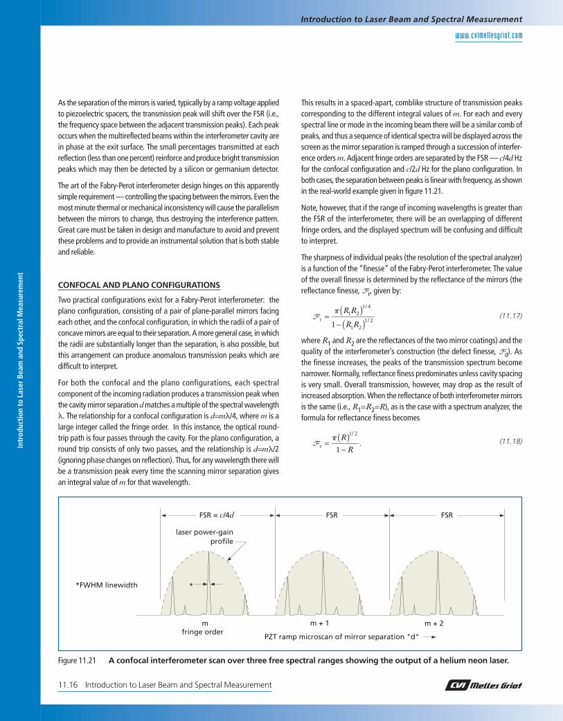
This results in a spaced-apart, comblike structure of transmission peakscorresponding to the different integral values of m. For each and everyspectral line or mode in the incoming beam there will be a similar comb ofpeaks, and thus a sequence of identical spectra will be displayed across thescreen as the mirror separation is ramped through a succession of interfer-ence orders m. Adjacent fringe orders are separated by the FSR — c/4d Hzfor the confocal configuration and c/2d Hz for the plano configuration. Inboth cases, the separation between peaks is linear with frequency, as shownin the real-world example given in figure 11.21.
Note, however, that if the range of incoming wavelengths is greater thanthe FSR of the interferometer, there will be an overlapping of differentfringe orders, and the displayed spectrum will be confusing and difficultto interpret.
The sharpness of individual peaks (the resolution of the spectral analyzer)is a function of the “finesse” of the Fabry-Perot interferometer. The valueof the overall finesse is determined by the reflectance of the mirrors (thereflectance finesse, Fr, given by:
where R1 and R2 are the reflectances of the two mirror coatings) and thequality of the interferometer’s construction (the defect finesse, Fd). Asthe finesse increases, the peaks of the transmission spectrum becomenarrower. Normally, reflectance finess predominates unless cavity spacingis very small. Overall transmission, however, may drop as the result ofincreased absorption. When the reflectance of both interferometer mirrorsis the same (i.e., R1=R2=R), as is the case with a spectrum analyzer, theformula for reflectance finess becomes
As the separation of the mirrors is varied, typically by a ramp voltage appliedto piezoelectric spacers, the transmission peak will shift over the FSR (i.e.,the frequency space between the adjacent transmission peaks). Each peakoccurs when the multireflected beams within the interferometer cavity arein phase at the exit surface. The small percentages transmitted at eachreflection (less than one percent) reinforce and produce bright transmissionpeaks which may then be detected by a silicon or germanium detector.
The art of the Fabry-Perot interferometer design hinges on this apparentlysimple requirement — controlling the spacing between the mirrors. Even themost minute thermal or mechanical inconsistency will cause the parallelismbetween the mirrors to change, thus destroying the interference pattern.Great care must be taken in design and manufacture to avoid and preventthese problems and to provide an instrumental solution that is both stableand reliable.
CONFOCAL AND PLANO CONFIGURATIONS
Two practical configurations exist for a Fabry-Perot interferometer: theplano configuration, consisting of a pair of plane-parallel mirrors facingeach other, and the confocal configuration, in which the radii of a pair ofconcave mirrors are equal to their separation. A more general case, in whichthe radii are substantially longer than the separation, is also possible, butthis arrangement can produce anomalous transmission peaks which aredifficult to interpret.
For both the confocal and the plano configurations, each spectralcomponent of the incoming radiation produces a transmission peak whenthe cavity mirror separation d matches a multiple of the spectral wavelengthl. The relationship for a confocal configuration is d=ml/4, where m is alarge integer called the fringe order. In this instance, the optical round-trip path is four passes through the cavity. For the plano configuration, around trip consists of only two passes, and the relationship is d=ml/2(ignoring phase changes on reflection). Thus, for any wavelength there willbe a transmission peak every time the scanning mirror separation givesan integral value of m for that wavelength.
laser power-gainprofile
*FWHM linewidth
m m + 1 m + 2fringe order
PZT ramp microscan of mirror separation "d"
FSR = c/4d FSR
*
FSR
Figure 11.21 A confocal interferometer scan over three free spectral ranges showing the output of a helium neon laser.
The FWHM is given by the ratio of the FSR to the finesse. Thus, for a high-resolution spectrum, the FSR should be small and the finesse high.
The defect finesse results from the inevitable residual imperfections inmanufacture. As the cavity spacing becomes small, overall surface defects,such as deviation from absolute parallelism or from absolute flatness(sphericity in a confocal interferometer), tend to predominate, but sur-face microroughness also contributes to the total defect finesse value.
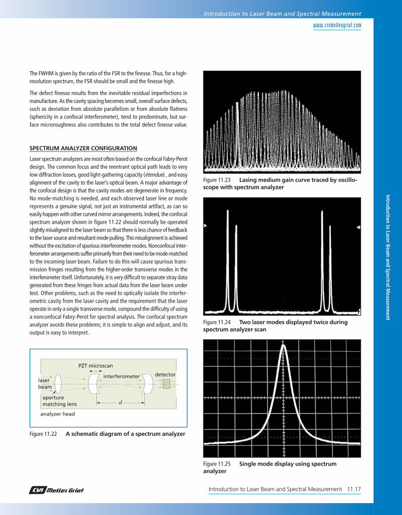
SPECTRUM ANALYZER CONFIGURATION
Laser spectrum analyzers are most often based on the confocal Fabry-Perotdesign. The common focus and the reentrant optical path leads to verylow diffraction losses, good light-gathering capacity (étendue) , and easyalignment of the cavity to the laser’s optical beam. A major advantage ofthe confocal design is that the cavity modes are degenerate in frequency.No mode-matching is needed, and each observed laser line or moderepresents a genuine signal, not just an instrumental artifact, as can soeasily happen with other curved mirror arrangements. Indeed, the confocalspectrum analyzer shown in figure 11.22 should normally be operatedslightly misaligned to the laser beam so that there is less chance of feedbackto the laser source and resultant mode pulling. This misalignment is achievedwithout the excitation of spurious interferometer modes. Nonconfocal inter-ferometer arrangements suffer primarily from their need to be mode-matchedto the incoming laser beam. Failure to do this will cause spurious trans-mission fringes resulting from the higher-order transverse modes in theinterferometer itself. Unfortunately, it is very difficult to separate stray datagenerated from these fringes from actual data from the laser beam undertest. Other problems, such as the need to optically isolate the interfer-ometric cavity from the laser cavity and the requirement that the laseroperate in only a single transverse mode, compound the difficulty of usinga nonconfocal Fabry-Perot for spectral analysis. The confocal spectrumanalyzer avoids these problems; it is simple to align and adjust, and itsoutput is easy to interpret.
Introduction to Laser Beam and Spectral M
easurement
www.cvimellesgriot .com
11.17Introduction to Laser Beam and Spectral Measurement
Introduction to Laser Beam and Spectral Measurement
aperturematching lens
interferometer detector
PZT microscan
laser beam
d
analyzer head
Figure 11.22 A schematic diagram of a spectrum analyzer
Figure 11.23 Lasing medium gain curve traced by oscillo-scope with spectrum analyzer
Figure 11.24 Two laser modes displayed twice duringspectrum analyzer scan
Figure 11.25 Single mode display using spectrumanalyzer
Introduction to Laser Beam and Spectral Measurement
Introduction to Laser Beam and Spectral Measurement11.18
lref
dref
d
reference beam
sample beam
sample detector
referencedetector
moving mirror
fixed mirror
l=dref
dlref
beamsplitter
Figure 11.26 A Michelson interferometer-basedwavemeter
displacement of the scanning mirror is known. In order to obtain highlyaccurate wavelength measurements, a reference laser with an accuratelyknown wavelength is measured simultaneously to determine the scanningmirror displacement in terms of this wavelength. With this type of instrument,measurements with an accuracy of 82 ppm can be obtained.
Interferometric wavemeters can be very accurate, but they are also veryexpensive, making them unsuitable for routine laboratory applicationsrequiring accuracy of a few tenths of a nanometer.
SEMICONDUCTOR-BASED WAVEMETERS
A new technique, used in the WaveMate™, may be the optimum solutionfor every-day low-resolution (~0.5 nm) measurements. In this technique,wavelength measurement is accomplished with a single photosensorconsisting of two stacked silicon photodiodes, as shown in figure 11.27.
The absorption characteristics of the first photodiode acts as a filter for thesecond photodiode. The two photodiodes have different spectral responsecurves (see figure 11.29).
By comparing the output of the two photodiodes, an intensity-independentsignal unique for the wavelength of the incident beam is obtained.
WaveMate consists of a sensor head and a console for processing anddisplay. The sensor head contains the photodiode, photoamplifiers, ther-mostat and a variable neutral density filter. In the console both signalsare error corrected and the wavelength is then calculated and displayed.
Measuring WavelengthWhen working with a laser, it is usually quite important to know thewavelength the laser is producing. With many this is not typically a prob-lem because the wavelength is defined to within a small fraction of ananometer by the physics of the lasing system. The red helium neon lineis always at 632.8 nm, the main blue argon-ion wavelength is always at488.0 nm, and so forth. However, when working with a tunable wave-length laser, or a laser than can experience significant wavelength driftas a function of temperature (e.g., a typical semiconductor diode laser),having an instrument available to determine the wavelength quickly withan acceptable level of accuracy is very useful.
Many systems have been developed over the years to measure the wave-length of light, whether from a laser, a lamp, or the output of an opticalexperiment. Traditionally, the light to be measured was collected and fedinto a spectrometer or grating monochromator. If the native accuracyof the monochromator readout was not sufficient, the result could becompared to the readout for closely spaced atomic lines from a spectralsource that bracketed the unknown wavelength, using proportional tech-niques. For highly accurate readings, however cumbersome long-pathinstruments were required, and, under the best of circumstances, wave-length measurement was a time-consuming task.
The advent of computers gave rise to a new class of instruments, thewavemeter, a table-top instrument that one could shine the unknownlight into and receive an immediate readout of the wavelength to a levelof accuracy that rivaled the best monochromator systems.
INTERFEROMETRIC WAVEMETERS
For absolute accuracy and precision wavemeters, interferometric techniqueshave proven the most practical. One common device is based on thescanning Michelson interferometer shown in figure 11.26.
The incident beam is split between a fixed path and a smoothly varyingpath. Both beams are reflected back and recombined at the beamsplit-ter to produce a sinusoidal interference pattern which results from thesmoothly changing phase relationship between the beams. The unknownwavelength of the incident light, l, can be calculated using the Michelsoninterferometer equation:
ml = 2nd.
In this equation, m is the number of fringes recorded as the scanningmirror of the Michelson interferometer moves through the distance, d. Therefractive index, n, of the medium (typically air) between the mirrors of theinterferometer is included to account for the difference between thephysical path distance and the optical path distance. The accuracy of thiswavelength calculation depends primarily on the precision to which the
Spectrometers, Monochromators,and SpectrophotometersA spectrometer is an instrument used to determine the wavelengths (andtheir relative intensities) present in a source of light. A monochromatoris an instrument used to separate out a single specific wavelength orwavelength band present in a source of light. The spectrophotometer isan instrument used to determine the wavelengths present in the lightreflected from an object.
All of these instruments share the same basic operating principal—lightfrom a source passes through, or is reflected by, a dispersing element whichspreads the light into its spectral colors. A detector then measures the inten-sity of the output at various points in the spectrum. The distinction amongthe instruments, illustrated in figure 11.30, is in the configuration of thesource of light, the dispersing element, and the detector.
In a spectrometer, the source is a lamp (or the output of an experiment), thedispersing element is stationary, and the detector is an array of detectors.
In a monochromator, the source is a lamp (or the output of an experiment),the dispersing element rotates, and a single detector is fixed in place.
In a spectrophotometer, the source is the light reflected from a sample, thedispersing element is stationary, and the detector is an array of detectors.
In most cases, the dispersing element is a ruled or holographic grating.In the monochromator, the detector is typically a photodiode or a pho-tomultiplier tube. In the spectrometer and spectrophotometer, thedetector is typically a linear CCD or CMOS detector with individualpixel readouts.
SPECTROMETER THEORY
A Czerny-Turner spectrometer is shown schematically in figure 11.31.
Light enters the optical bench through a slit and is collimated by aspherical mirror. A plane grating diffracts the collimated light; a cylindricalmirror then focuses the resulting diffracted light. An image of the spectrumis projected onto a one-dimensional linear detector array.
Intr
oduc
tion
to L
aser
Bea
m a
nd S
pect
ral M
easu
rem
ent
www.cvimellesgriot .com
Introduction to Laser Beam and Spectral Measurement
Introduction to Laser Beam and Spectral Measurement11.20
SPECTROMETER MONOCHROMATOR SPECTROPHOTOMETER
source source
source
exit slit
entrance slit
entrance slit
entrance slit
fixed grating
fixed grating
rotating grating
detectorarrayor film
detectorarray
detector
collectinglens
collectinglens
collectinglens
Figure 11.30 The spectrometer family
fiber-opticinput connector
entranceslit
detectorarrayfocusing
mirror
fixed grating
collimatingmirror
Figure 11.31 Schematic of symmetric Czerny-Turnerspectrometer
11.21Introduction to Laser Beam and Spectral Measurement
Introduction to Laser Beam and Spectral Measurement
From these equations it is clear that increasing the distance from thefocusing mirror to the detector spreads the spectrum over a wider area,increasing the dispersion and, in principle, increasing the resolving powerof the instrument.
RESOLVING POWER
Resolution is the ability of an instrument to separate adjacent spectral lines,and is given by the equation
where dl is the difference in wavelength between two spectral lines ofequal intensity. It may be shown that
whereWg=the illuminated width of the grating and N=the total number of grooves in the gratings.
Using the earlier equations, it can also be shown that
Obviously, the resolving power of a spectrometer depends on the width of thegrating, the geometry, and the wavelength to be resolved. The size of theincoming light at the entrance aperture is determined by the slit width or,in the absence of a slit, the fiber diameter.
WAVELENGTH AND ORDER
Unlike a dispersing prism, a diffraction grating does not produce a singlespectra, but instead it produces multiple spectra determined by theequation
kl=constant
where k is an integer. Consequently, for a broad spectral source, thespectra will overlap. For example, at the detector location for800 nm, output at 400 nm, 266.6 nm, and 200 nm will also be present.Consequently, filters must be used to eliminate the higher-order spectra.
BLAZED GRATINGS
Blazed gratings are designed to produce maximum efficiency at a specificwavelength. This is accomplished by forming the grooves in such a mannerthat the incident and refracted angle, at that wavelength, are equal (theLittrow condition). A grating that is blazed for a first-order wavelength,will also be blazed for the corresponding higher-order wavelengths.
The fundamental grating equation is as follows:
sina=sinb=1046knl
wherea is the angle of incidence in degreesb is the angle of diffraction in degreesk is the diffraction order (an integer)n is the grating density in lines/mml is the wavelength of light in nm
and the angular separation (angular dispersion) between two wavelengths,in radians, is given by
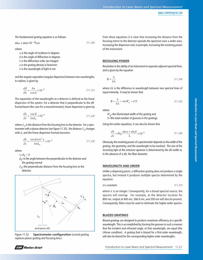
The separation of the wavelengths at a detector is defined as the lineardispersion of the system. For a detector that is perpendicular to the dif-fracted beam (the case for a monochromator), linear dispersion is given by
where Lb is the distance from the focusing lens to the detector. For a spec-trometer with a planar detector (see figure 11.32) , the distance Lb changeswith b, and the linear dispersion formula becomes
whereg=bh4b
bh=is the angle between the perpendicular to the detector andthe grating normal
Lh=the perpendicular distance from the focusing lens to thedetector.
As a laser beam propagates, its width and spatial intensity distribution willchange in space and time owing changes in the laser cavity, divergence,and interaction with optical elements. Spatial intensity distribution is one ofthe fundamental parameters that indicates how a laser beam will behavein an application. Laser printing, material processing, fiber optic coupling,optical data storage, laser pumping, and photochemistry are some of the appli-cations whose efficiency depends on a laser’s spatial intensity profile andbeam width. Theory can sometimes predict the behavior of a beam, butmanufacturing tolerances in lenses and mirrors, and ambient conditionsaffecting the laser cavity, necessitate verification. Consequently, it is crucialfor researchers, system designers, and laser manufacturers to be able tomeasure accurately these parameters. ISO standard 11146 defines approachesto be used in measuring such beams. All CVI Melles Griot products are in fullconformance with this standard.
DEFINING BEAM WIDTH
The boundaries of optical beams are not clearly defined and, in theory at least,extend to infinity. Consequently, the dimensions of a beam cannot be definedas easily as the dimensions of hard physical objects. The commonly useddefinition of beam width is the width at which the beam intensity has fallento 1/e2 (13.5%) of its peak value when measured in a plane that is orthog-onal to the optical axis. This is derived from the propagation of a Gaussianbeam and is appropriate for lasers operating in the fundamental TEM00mode (see figure 11.33).
Many lasers, however, exhibit a significant amount of beam structure, andapplying this simple definition leads to problems. Therefore, the ISO 11146standard specifies the beam width as the 1/e2 point of the second momentof intensity, a value that is calculated from the raw intensity data and whichreduces to the common definition for a Gaussian beam.
Fundamentals of Beam Profilingand Beam Measurement
METHODS OF MEASURING BEAM WIDTH
There are four main types of beam-profiling instrumentation: camera-basedsystems, knife-edge scanners, slit scanners, and pinhole scanners. Each hasspecific advantages and disadvantages. Different measurement techniquesmay result in slightly different results; therefore, it is critical that compara-tive measurements be made with the same technique.
Camera-Based Profilers
Camera-based profilers use a two-dimensional array of square or rectangularpixels as the imaging device,which, much like photographic film, instantlyrecord and display the entire optical pattern that impinges on the camerasurface. The intensity distribution of a laser beam is recorded pixel by pixeland displayed as either a topographic or three-dimensional contour plot.The advantage of such profilers is that they can detect and display anystructure that may exist on the profile. They can display two- and three-dimensional plots of profiles, and they can be used with both cw andpulsed lasers. The chief disadvantage of these instruments is that theirmeasurement resolution is limited by pixel size (usually between 5 and 10mm on a side), which, in general, limits their use to measuring beamsgreater than ~60 mm in width. A new class of camera-based profiler, themBeam™, overcomes this size limitation by magnifying the laser beam,in a calibrated manner, by a factor of up to 100#. This allows profilingof beams less than 5 mm in diameter but limits the maximum beamdiameter to about 50 mm. Another disadvantage is limited spectral range.
Two types of image detectors are used in CVI Melles Griot beam camera-based profilers—charge-coupled device (CCD) detectors and complemen-tary metal-oxide semiconductor (CMOS) detectors. In general, CCDdetectors have a greater dynamic range and lower noise than CMOSdetectors, but they are somewhat slower and require much more complexcircuitry. In camera-based beam profilers, the performance differencesare minor. One clear advantage of a CMOS detector is that the failure ofpixel can shut down a complete row because of the way in which chargetravels through the detector.
Knife-Edge, Slit, and Pinhole Profilers
All three of these instruments generate a profile by mechanically movingan aperture across the beam in a plane orthogonal to the optical axis.The light passing through the aperture is measured by a detector andcorrelated with the position of the aperture as it crosses the beam. Unlikecamera-based scanners, which measure a profile in three dimensions(x, y, intensity), scanners measure only two dimensions at a time (x andintensity or y and intensity). Consequently, three-dimensional represen-tations generated by these systems are calculated, not measured, andthe accuracy or the reconstruction depends upon basic assumptionsmade about the beam characteristics and the algorithms used in thereconstruction.
Intr
oduc
tion
to L
aser
Bea
m a
nd S
pect
ral M
easu
rem
ent
www.cvimellesgriot .com
Introduction to Laser Beam and Spectral Measurement
Introduction to Laser Beam and Spectral Measurement11.22
13.5
CONTOUR RADIUS-1.5w 1.5w
20
40
60
80
100
-w 0 w
PER
CEN
T IR
RA
DIA
NC
E I(
r)
(P = total power in beam)
pw2I(r) = 2P
e-2r
2
w 2
Figure 11.33 Gaussian profile of a TEM00 mode (note thebeam radius w at the 1/e2 (13.5%) intensity level)
Pinhole profilers use a small pinhole as the aperture and plot the trans-mitted power vs position. The resolution of the profile is determined bythe size of the aperture. The chief advantage of a pinhole profiler is itsability, within the resolution, to create an exact profile of a plane througha portion of the beam. The disadvantages are that the transmitted powerthrough the pinhole is very small, aligning the pinhole is extremely dif-ficult, and multiple positional measurements are needed to generate aprofile of the entire beam.
Scanning Slit Profilers
Slit profilers use a long narrow aperture which encompases the full widthof the beam in a direction perpendicular to the travel of the slit. It then plotsthe transmitted power through the slit vs position. Unlike the pinholescanner, the slit scanner scans through the entire beam, not just a singleplane. However, unless the beam is circularly symmetric and near Gaussian,the profile may not be an exact representation of the intensity profile.Like pinhole scanners, the resolution of the scan is a function of the widthof the slit, and the narrower the slit, the less light reaches the detector,decreasing the signal-to-noise ratio.
Scanning Knife-Edge Profilers
Knife-edge profilers use an aperture large enough to pass the entire beam.The aperture has one sharp, straight edge (knife edge). As the aperturetraverses the beam, the system measures the portion of the beam that isnot blocked by the blade (see figure 43.34) and plots the differential (rateof change in intensity) vs positon of the power through the aperture.
This has several advantages when compared to a slit or pinhole scans:The beam intensity is not limited by the size of the pinhole or slit width,so the signal-to-noise ratio is very high; resolution is not limited by thesize of the aperture, allowing beams of a few microns in diameter to bemeasured; and because, at some point in the scan the full beam strikesthe detector, accurate power and noise measurements can be taken. Likethe slit scanner, the accuracy of a scan depends upon the geometry of thebeam. For best results, the beam should be circularly symmetric and nearGaussian.
Tomographic Scanning
As discussed above, scanning slit and knife-edge scanners cannot generatetruly accurate three-dimensional reconstructions of laser beam profiles.Reasonable approximations can be made, however, by using tomographictechniques—the same techniques used with MRI and CAT scanners tocreate three-dimensional images of internal organs. The key to makingthese reconstructions is to scan the beam in as many different directionsas possible. For useful tomographic analysis, scans from at least threedifferent directions are needed. If scans could be made from 10 or moredirections, the three-dimensional reconstruction would be highly accurate.
CVI Melles Griot offers two knife-edge systems that use tomographicalgorithms to construct three-dimensional profiles. The BeamAlyzer™system has a three-blade scan, and the Super BeamAlyzer™ has a seven-blade scan (see figure 11.35). For most beams, the Super BeamAlyzer’sreconstructions rival those measured directly with a camera-based scanner. Introduction to Laser Beam
and Spectral Measurem
ent
www.cvimellesgriot .com
11.23Introduction to Laser Beam and Spectral Measurement
Introduction to Laser Beam and Spectral Measurement
detector
rotating drum
knife-edge
laser beam
attenuatingfilter
Figure 11.34 Simplified mechanics of a knife-edge beamprofiler
direction of drum rotation
footprint of laser beam
knife-edge
Figure 11.35 Orientation of the knife edges on the7-blade Super BeamAlyzer™ tomographic beam profiler
where l is the wavelength of the beam, W0 is the beam waist, and v0 is thefar-field divergence of the beam. The propagation factor is an invariant thatdescribes the relationship of a non-Gaussian beam to a Gaussian beamas it passes through an optical system. If k=M=1, the beam is Gaussian.If k<1 (M2>1), the beam is not Gaussian, but all of the standard Gaussianpropagating formulas may be used with appropriate modifications (e.g.,W0=M#w0, v0=M#v0 where w0 and v0 are the corresponding Gauss-ian parameters). Indeed, the concept of an “embedded Gaussian” hasbeen introduced as a construct to assist with both theoretical modelingand laboratory measurements (see figure 11.36).
Intr
oduc
tion
to L
aser
Bea
m a
nd S
pect
ral M
easu
rem
ent
www.cvimellesgriot .com
Introduction to Laser Beam and Spectral Measurement
Introduction to Laser Beam and Spectral Measurement11.24
kM W
= =1
2
0
l
p v
2wR(R) = M[2w (R)] = M(2w0√2)
2v
z
embeddedGaussian
mixedmode
2w0R = M(2w0)
2w0
z = 0 z = R
M(2v)
Figure 11.36 The embedded Gaussian concept A mixed-mode beam which has a waist M (not M2) times larger than the embedded Gaussianwill propagate with a divergence M times greater than the embedded Gaussian, and the mixed-mode width will always be M times the embeddedGaussian width, but will have the same radius of curvature and the same Rayleigh range
rotating drumscanner
detector
measurementplane
moving lens
Figure 11.37 A simple moving-lens MM2 setup
(11.28)
MM2 Measurement
A variety of instruments have been developed to measure the propagationfactor and M2 in the laboratory. Most are based on the same funda-mental operating principle; the incoming laser beam is focused by a lens.This creates a beam that has a beam waist at the focal point, a near-fielddivergence region (within the Raleigh range), and a far-field region (many,many times the Rayleigh range) all within a distance of a few inches.Using a beam profiler, the beam diameter at the waist and the diametersat near-field and far-field points on either side of the waist are measured.A computer then fits a hyperbolic curve to the data and, using the fun-damental Gaussian formulas, calculates the beam waist and divergenceof the embedded Gaussian, M2, the location of the beam waist in theincoming laser beam, and other critical parameters. A schematic diagramof a simple M2 moving lens device is shown in figure 11.37.