Page 1
7/14/2011
1
AS/NZS 7000:2010
Worked Examples
11kV Single Circuit Concrete Poles
9.2m
1.8m
Single CircuitLV or 11 kV
Worked Example 1
11kV Single circuit pole line
Ground Line
9.2m
1.8m
Single Circuit
Maximum change in line direction is 10 degrees
Line INLINE POLE
Page 2
7/14/2011
2
Line Design ParametersComponent Detail Reference
Location Coastal plain North
Island
Terrain Flat / undulating
Exposure Terrain Cat 2 AS/NZS 1170.2
Design working life 50yrs Table 6.1 AS/NZS 7000
Design security level Level 1 Table 6.1 AS/NZS 7000
Design Wind RP 50yrs Table 6.1 AS/NZS 7000
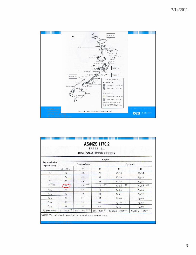
Design Wind velocity VR
39.0 m/s Region A7 AS/NZS 1170.2 Table
3.1
Lee wind area No Fig B2 AS/NZS7000
Topographic multiplier M t
1.0 Cl. B3 AS/NZS7000
Directional multiplier Md
1.0 Cl. B3 AS/NZS7000
Terrain multiplier Mzcat
1.0 Table 4.1 AS/NZS1170.2
Ice load Nil Appendix EE AS/NZS7000
Selection of design wind return period
Australian Panel B2 –Overhead Lines Seminar –AS/NZS Overhead Line Design Sydney 28 -29 March 2011
Page 3
7/14/2011
3
Australian Panel B2 –Overhead Lines Seminar –AS/NZS Overhead Line Design Sydney 28 -29 March 2011
Australian Panel B2 –Overhead Lines Seminar –AS/NZS Overhead Line Design Sydney 28 -29 March 2011
AS/NZS 1170.2
Page 4
7/14/2011
4
Line Design Parameters
Component Detail Reference
Pole type 11.0m Prestressed concrete
Conductor ‘Dog’ ACSR
Earthwire Nil
Wind span 70m
Weight span 70m
Deviation angle 10 degrees
Pole details
Item Assumed Pole Details
Pole type 11m PSC Rectangular I
section
Embedment Depth 1.8m
Conductor attachment Ht 9.2m
Transverse Base width @GL 430mm
Longitudinal Base width @GL 150 mm
Transverse Tip width 160 mm
Longitudinal tip width 150 mm
Pole tip load longitudinal capacity 8.0kN
Pole tip load transverse capacity 22.0kN
Assume max bending moment 200mm below ground level
Page 5
7/14/2011
5
Conductor details
DOG ACSR VALUE UNIT
Everyday Temperature (EDT): 10 DegC
Minimum Temperature: -5.76 DegC
Maximum Design Temperature: 50 DegC
Stringing Temperature: 15 DegC
Stringing Tension, 10% UTS 3.00 kN
Stringing Tension, (EDT) 3.29 kN
Nominal Overall Diam: 14.2 mm
Cross Sectional Area: 118.8 m2
Initial Mod Of Elasticity: 56.54 x 10⁹ Pa
Ultimate Tensile Strength: 3357 kg
32.93 kN
Self weight: 0.396 kg/m
0.00388 kN/m
Wind Pressures
Unit Design Wind Pressures:Regional site design wind velocity
Unit Design Wind Pressure
Vsit
,β
qz
==
VR
Md
Mz,cat
Ms M
t=39m/s ( Cl B3 AS/NZS 7000)
= 913 Pa
Element Design Wind Pressures:
Conductors (Cd = 1.0): = 913 x 1.00 (Design Wind Pressure x Drag Force Coef)
= 913 Pa
Pole (Cd = 1.6): = 913 x 1.6 (Design Wind Pressure x Drag Force Coef)
= 1460 Pa
Crossarm End (Cd = 1.2): = 913 x 1.2 (Design Wind Pressure x Drag Force Coef)
= 1096 Pa
Insulators (Cd = 1.2): = 913 x 1.2 (Design Wind Pressure x Drag Force Coef)
= 1096 Pa
2 3,0.6 10 (kPa)sitV β
−× ( Cl B5 AS/NZS 7000)
Page 6
7/14/2011
6
Australian Panel B2 –Overhead Lines Seminar –AS/NZS 7000 :2010 Overhead line Design Sydney 28-29 March 2011
Design Load Combinations
Conductor Applied LoadsLoad Condition Symbol Design Load
Everyday load condition, 10 DegC, no wind Fat 3.27 kN
Sustained load condition, -5.76 DegC, no wind Fat 4.57 kN
Sustained load condition, 00C, no wind Fat 3.99 kNMaximum wind load condition, 0 DegC, Wind = 913 Pa Ftw 8.76 kN
Maximum wind load condition, minimum temperature -5.76 DegC, Wind = 913 Pa Ftw 9.26 kN
Failure Containment, 10 DegC, max. wind x 0.25 Fb 3.97 kN
Page 7
7/14/2011
7
Check Conductor Design Tensions
For ultimate loading conditions:
Ultimate Tensile Strength of conductor Rn = 32.93 kN
Conductor Capacity ØRn = 23.05 kN (Material Ø Factor = 0.7 Table 6.2 AS/NZS 7000)
Under maximum wind condition:
Conductor tension = 1.25 x Fat
= 1.25 x 8.76
= 10.95 kN < ØRn
Under minimum temperature condition:
Conductor tension = 1.25 x Fat
= 1.25 x4.57
= 5.71 kN < ØRn
Therefore OK for DOG conductor
Check loads on pin insulatorsMaximum transverse wind load from
conductor on insulator Tiw
= Azx Conductor wind pressure
= (Diam x Span x SRF) x Conductor wind pressure
= 14.2/1000 x 70 x 1 x 913/1000
= 0.91 kN < (0.85 x 9.6) kN for 1130W,
Line deviation transverse conductor load
under maximum wind load Tid
= 2 x Fat
x
= 2 x 8.76 x sin(5)
= 1.53 kN
Sum of design ultimate loads at conductor
level on top of insulator: ∑kiTi = k
ix Wind load + 1.25 x deviation load
= 0.75x0.91+1.25x1.53
= 2.59 kN < (7÷2) or 3.5 kN for 1130W,
< (0.85 x 9.6) kN for M20 high tensile pin,
Maximum vertical load from conductor Vu
= Span x weight per m
(No ice or snow) = 70 x 0.00388 x 1.1
(Load Factor 1.1 from Table 7.3 AS/NZS
7000)
= 0.30 kN < (7÷2) kN for 1130W, OK
Use 1130W, Pin M20 High Tensile
2sin
θ
Page 8
7/14/2011
8
Check Conductor Separation at Midspan
Clause 3.7.3.2 of AS/NZS 7000:2010 provides
Where; X = Projected horizontal distance (m) between conductors midspan
Y = Projected vertical distance (m) between conductors midspan
U = r.m.s. vector difference in potential (kV)
k = Constant, normally equal to 0.4
D = Greater of two conductor sags centre equiv. span, 50 DegC, still air
l = Length in metres of any free swing conductor
In this structure case
Y = 0 m;U = 11 kV; k = 0.4 ; D = 1.14 m ; and l = 0 m
Therefore; X ≥ 11 / 150 + 0.4 x √ (1.142 + 0) ≥ 0.529 m
and X = (X1 + X2)/2 = (300 + 950)/2 for 1400 x 100 x 75 HW crossarm,
Ie X1 = 300, X2 = 950
Distance between conductors midspan X = 0.625 m
Minimum required separation; ≥ 0.529
OK for 1400 x 100 x 75 HW crossarm and electrical separations are OK
2 2(1.2 )150
UX Y k D l+ ≥ + +
HW Crossarm DesignCheck conductors vertical loads Vertical Bending in crossarm:
Vertical Load of conductors = unit weight x weight span x 9.806
= .00388x70 = .27kN
For intermediate suspension structures the conductor vertical loads are very small and
would only govern design where ice loads apply and for design spans > 250m.
Here, span = 70m .
Therefore OK
Check conductors horizontal loads: (Assuming loads are transferred through to pole via
a single bolts in shear and stabilized by standard flat plate braces)
Ultimate horizontal load ∑Wu = (ki x Wind load + 1.25 x deviation load) x 3
= ((0.75 x 0.91) + (1.25 x 1.53))x 3
i.e. N = 7.76 kN
Page 9
7/14/2011
9
Timber Joint Design (Crossarm to Pole)
Now for a M16 Grade 4.6 bolt
Qskl = 23.4 kN for Joint Group J1 (ironbark) Table 4.9(B) AS 1720.1
where beff = 75 mm (parallel to grain) & single shear
so design capacity; ØNj ≥ N*
ØNj = Ø k1 k16 k17 n Qskl (Clause 4.4.3.2 of AS1720.1 – 1997)
where Ø = 0.8;
k1 = 0.57 (duration of load - say permanent for deviation);
k16 = 1 ( bolt loads not transferred by side plates);
k17 = 1 (from Table 4.11 AS 1720.1);
n = 1 (No. of bolts = 1)
therefore ØNj = 10.67 kN ≥ 7.76 kN
OK for M16 bolt to pole in 75mm wide crossarm,
1400 x 100 x 75 HW crossarm OK
Concrete pole designTransverse design wind loads:
1. Wind on Pole:
Wnpole = Pole Az x Pole wind pressure
= 9.2x(0.24+0.15)/2 x 1460/1000
= 2.62 kN
This force acts at height =((0.240.15)x9.2/2x9.2/3+(0.15x9.2x9.2/2)/(9.2x(0.24+0.15)/2
= 4.25 m
2. Wind on Crossarm:
Wncrossarm = Crossarm Az x Crossarm wind pressure (assume 100 x 75mm)
= (0.1 x 0.075) x 1096/1000
= 0.01 kN This force acts at height of: 9.20 m
Page 10
7/14/2011
10
Concrete pole design
3. Wind on Conductors:
Wncond = Conductor Az x Conductor wind pressure (3 conductors)
= 3 x (Diam x Span x SRF ) x Conductor wind pressure
= 3 x (14.2/1000 x 70 x 1) x913/1000
= 2.72 kN This force acts at height of 9.20 m
(Ref Fig B5 and B6 of AS/NZS 7000 for SRF )
4. Wind on Insulators:
(assume 150 x 129mm projected area)
Wninsul = Insulator Az x Insulator wind pressure
= 3 x (0.150 x 0.129) x 1367/1000
= 0.08 kN This force acts at height of 9.20 m
Concrete pole design
Line deviation loads:
Line deviation angle =10 degrees
Tid
=2 x Fat
x sin 10/2
=2 x 8.76 x sin(5)
=1.53kN
Determine pole design overturning moments:
Taking moments about ground line for the maximum wind and weight loading
condition
∑(BM) = 1.0 Wn +1.1 Gs +1.25 Gc + 1.25 Ftw
= 1.0 ((2.62 x 4.25) + (0.01 x 9.2) + (2.72 x 9.2) + (0.08 x 9.2)) + 1.1 ( 3x .27 x .75) +
1.25 (3 x 1.53 x 9.2 )
= 90.435 kN-m
Assume 9.28 m effective cantilever ( ie 9.20 O/A above ground +200 - 120 to king bolt)
Pole design transverse tip load = 90.43 / 9.28
= 9.74 kN Pole Capacity
Page 11
7/14/2011
11
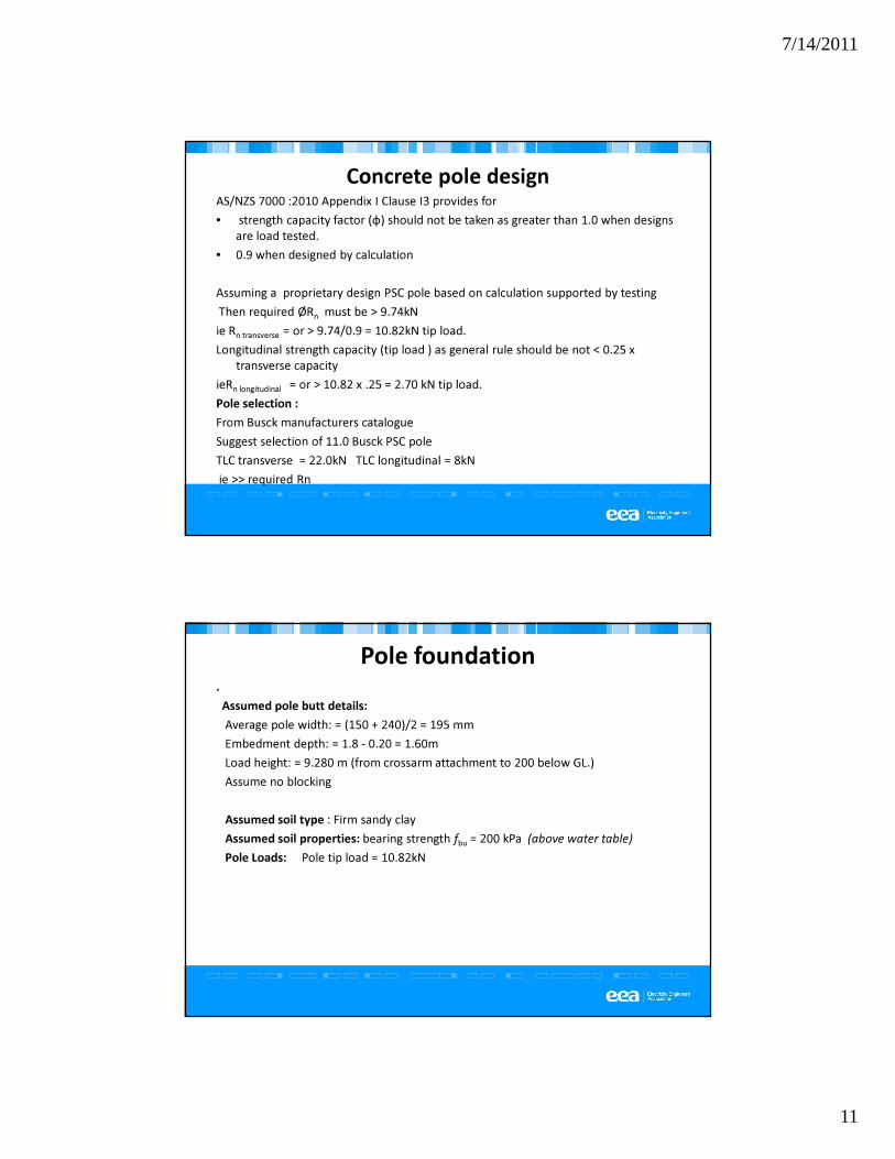
Concrete pole designAS/NZS 7000 :2010 Appendix I Clause I3 provides for
• strength capacity factor (φ) should not be taken as greater than 1.0 when designs
are load tested.
• 0.9 when designed by calculation
Assuming a proprietary design PSC pole based on calculation supported by testing
Then required ØRn must be > 9.74kN
ie Rn transverse = or > 9.74/0.9 = 10.82kN tip load.
Longitudinal strength capacity (tip load ) as general rule should be not < 0.25 x
transverse capacity
ieRn longitudinal = or > 10.82 x .25 = 2.70 kN tip load.
Pole selection :
From Busck manufacturers catalogue
Suggest selection of 11.0 Busck PSC pole
TLC transverse = 22.0kN TLC longitudinal = 8kN
ie >> required Rn
Pole foundation.
Assumed pole butt details:
Average pole width: = (150 + 240)/2 = 195 mm
Embedment depth: = 1.8 - 0.20 = 1.60m
Load height: = 9.280 m (from crossarm attachment to 200 below GL.)
Assume no blocking
Assumed soil type : Firm sandy clay
Assumed soil properties: bearing strength fbu = 200 kPa (above water table)
Pole Loads: Pole tip load = 10.82kN
Page 12
7/14/2011
12
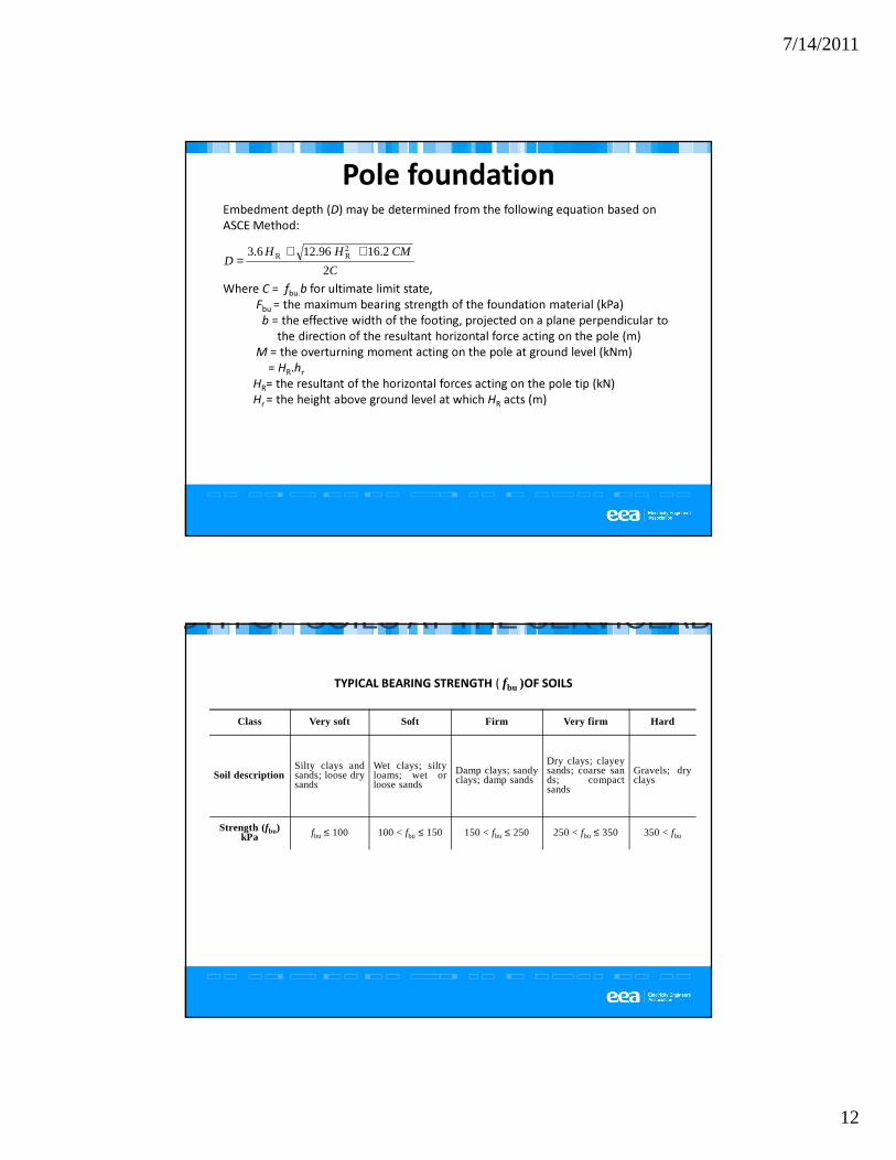
Pole foundationEmbedment depth (D) may be determined from the following equation based on
ASCE Method:
Where C = fbu.b for ultimate limit state,
Fbu = the maximum bearing strength of the foundation material (kPa)
b = the effective width of the footing, projected on a plane perpendicular to
the direction of the resultant horizontal force acting on the pole (m)
M = the overturning moment acting on the pole at ground level (kNm)
= HR.hr
HR= the resultant of the horizontal forces acting on the pole tip (kN)
Hr = the height above ground level at which HR acts (m)
C
CMHHD
2
2.1696.126.3 2RR ++
=
TYPICAL BEARING STRENGTH ( fbu )OF SOILS
Class Very soft Soft Firm Very firm Hard
Soil descriptionSilty clays andsands; loose drysands
Wet clays; siltyloams; wet orloose sands
Damp clays; sandyclays; damp sands
Dry clays; clayeysands; coarse sands; compactsands
Gravels; dryclays
Strength (fbu) kPa fbu ≤ 100 100 < fbu ≤ 150 150 < fbu ≤ 250 250 < fbu ≤ 350 350 < fbu
BEARING STRENGTH OF SOILS AT THE SERVICEABILITY LIMIT STATE
Page 13
7/14/2011
13
Compacted Soil Footing:
Assume standard heel block (490 x 225)
b = 490 mm
h = 225 mm
Average pole width b = ((240 -(240-150)/3) + 240)/2
= 225 mm
Applying values to formula D = 3.44m > 1.60 available
Stabilized backfill footing :
Assume use compacted stabilised backfill or compacted road base backfill in 600 dia
bored hole with standard heel block. ie b=600
Applying assumed soil values D= 2.00m > 1.60 available
Note: Neither of these two alternatives are acceptable. This is due to the high O/T
moment being applied by the deviation loads (52.78kNm out of 90.43kNm )
Alternative stabilized backfill footing :
Assume use compacted stabilised backfill or compacted road base backfill in
900 mm dia. bored hole with standard heel block. ie b=.900m
Applying assumed soil values D= 1.6m c/w 1.6 available and would be OK
Page 14
7/14/2011
14
Breast Block Alternative:
Once breast logs are utilised the overturning moments are
resisted by reaction mobilised by the bearing blocks and
base block
Assume 1200wide x 360 deep block 200 below GL
Resolving BM’s around pinned base
Rbreast = 10.82 x (9.280 +1.60) / (1.60 - 0.180) = 82.49 kN
Rbase = 82.49 – 10.82 = 72.08 kN
Bearing block area = 1.2 x .360 = .432 m2
Bearing pressure = 82.49/.432=195kPa < 200 kPa assumed
Stay
θ
Rh
RV
Ts
Back stay alternative :
Due to the high O/T moment being applied by the deviation
loads (52.78kNm out of 90.43kNm ) this option may be more
suitable in soft soil sites
OTM on pole = 90.43 kNm
Assume stay attachment point is at crossarm brace bolt at
330 mm below crossarm attachment point
Stay attachment height = 9.28- 0.33 = 8.95m
Therefore Rh = 90.43/8.95 = 10.10 kN
Stay Tension Ts = Rh / Cos45 = 14.28kN
9.5mm dia stay wire has rated capacity of 45kN
Use 9.5mm stay wire and standard dead man anchor
Vertical load component of stay load = Rh x tan45 =14.28kN
This is a relative small vertical load on the pole and is OK
Page 15
7/14/2011
15
Questions?
Australian Panel B2 –Overhead Lines Seminar –AS/NZS Overhead Line Design Sydney 28 -29 March 2011