Page 1
Distributed SystemsDistributed Systems
12 12 CoordinationCoordination
June 22/24/29 2009Gerd Liefländer
System Architecture Group
© 2009 Universität Karlsruhe (TH), System Architecture Group 1
Page 2
Outline: Next Lectures
Coordination Problems Global State
Failure Detection
Mutual Exclusion
Overview
© 2009 Universität Karlsruhe (TH), System Architecture Group 2
Election
Multicast
Consensus
Deadlocks
Distributed Transactions
Recommended reading:Tanenbaum, Ch. 5, 7, Coulouris/Dollimore/Kindberg, Ch. 11, 12, 13
Page 3
Motivation
Given an asynchronous DS, i.e. no process has a view of the current global state of the DS
Need to coordinate the actions of cooperating processes to achieve common goals Failure detection: how to know in an asynchronous network
whether my peer is dead or alive?
© 2009 Universität Karlsruhe (TH), System Architecture Group 3
Mutual exclusion: how to guarantee that no two processes will ever get access to a critical section at the same time?
Election: how will the system elect a new master in a master-slave based distributed application?
Multicast: how to enhance when sending to a group of recipients that reliability of the multicast (i.e. correct delivery, only once,
etc.) preservation of the order of the messages
Page 4
Global StateGlobal State
4© 2009 Universität Karlsruhe (TH), System Architecture Group
Chandy/Lamport: Distributed Snapshots: Determining Global States of DShttp://research.microsoft.com/users/lamport/pubs/chandy.pdf
Dijkstra: Comments on Chandy/Lamport/Misra Algorithmhttp://www.cs.utexas.edu/users/EWD/transcriptions/EWD08xx/EWD864.html
Michael L. Powell and David L. Presotto,“PUBLISHING: A Reliable Broadcast Communication Mechanism, Proceedings of the Ninth ACM Symposium on Operating Systems Principles, Oct 83.
Ozalp Babaoglu and Keith Marzullo: Consistent Global States of Distributed Systems: Fundamental Concepts and Mechanisms, in Distributed Systems, Sape J. Mullender, Addison-Wesley, 1993.
Page 5
Outline of this Chapter1
Complexities of state detection in DS The notion of consistent state The distributed snapshot algorithm
(Chandy/Lamport)
5
(Chandy/Lamport) Application to detect stable properties and
checkpointing Another approach for global state recording:
publishing
1 Most slides on Global State are from Sanjeev R. Kulkarni (Princeton Uni)
© 2009 Universität Karlsruhe (TH), System Architecture Group
Page 6
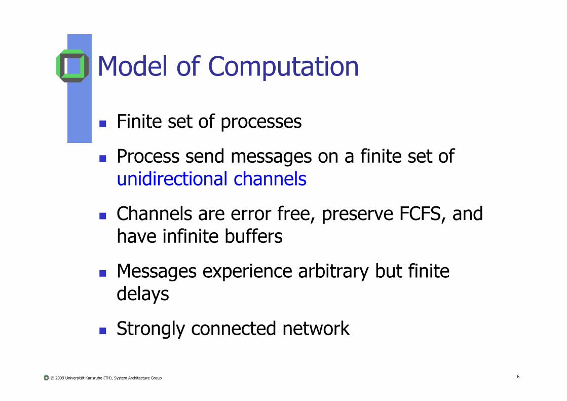
Model of Computation
Finite set of processes
Process send messages on a finite set of unidirectional channels
6
Channels are error free, preserve FCFS, and have infinite buffers
Messages experience arbitrary but finite delays
Strongly connected network
© 2009 Universität Karlsruhe (TH), System Architecture Group
Page 7
Model of Computation (cont.)
A computation is a sequence of events. An event is an atomic action that changes the
state of a process and at most one channel state that is incident on that channel.
7
Arcs indicate a message transfer
p
q`
Sp0 Sp
1 Sp2 Sp
3
Sq0 Sq
1 Sq2 Sq
3
© 2009 Universität Karlsruhe (TH), System Architecture Group
Page 8
Happened Before Relation
Events e and e` of the same process. if e happens before e` then e e`
e and e` in two different processes
8
if e = send(m) and e` = recv(m) then e e`
Transitive if e e` and e` e`` then e e``
© 2009 Universität Karlsruhe (TH), System Architecture Group
Page 9
Determining Global State
Global State“The global state of a distributed computation is the set of local states of all individual processes involved in the computation plus
9
p o ss s o d o pu a o p usthe state of their communication channels.”
© 2009 Universität Karlsruhe (TH), System Architecture Group
Page 10
More on States
process state memory state + register state + signal masks +
open files + kernel buffers + … or
10
application specific info like transactions completed, functions executed etc.
channel state “Messages in transit” i.e. those messages that
have been sent but not yet received
© 2009 Universität Karlsruhe (TH), System Architecture Group
Page 11
Why to deal with Global States?
Many problems in distributed computing can be cast as executing some action on reaching a particular state
e.g.
distributed deadlock detection is finding a cycle in
11
g ythe wait for graph.
termination detection
check pointing
some more…..
© 2009 Universität Karlsruhe (TH), System Architecture Group
Page 12
Snapshot Problem
Suppose computation of a distributed application hasbecome passive on each involved node
We want to be able to distinguish whether a distributed application
Global States
© 2009 Universität Karlsruhe (TH), System Architecture Group 12
pp
1. is temporarely blocked
2. has “terminated” or
3. is deadlocked
Page 13
Snapshot Problem
Garbage collection
Global States
waits for
© 2009 Universität Karlsruhe (TH), System Architecture Group 13
Deadlock
Termination problemwaits for
waits for
passive
terminated
passive
terminated
Page 14
Why is Global State difficult in DS?
Distributed state: Have to collect information that is spread across several machines!!
14
Only local knowledge: A process in a distributed computation might not really know the current states of the other processes
© 2009 Universität Karlsruhe (TH), System Architecture Group
Page 15
Difficulties
Instantaneous recording not possible
No global clock: the distributed recording of local t t t b h i d b d ti
15
states cannot be synchronized based on time Some local states reflect an outdated state, some
reflect the current state
Random network delays: no centralized process can initiate the detection
© 2009 Universität Karlsruhe (TH), System Architecture Group
Page 16
Difficulties due to Non Determinism
Deterministic Computation At any point in computation there is at most one
event that can happen next.
16
Non-Deterministic Computation At any point in computation there can be more
than one event that can happen next.
© 2009 Universität Karlsruhe (TH), System Architecture Group
Page 17
Example: Deterministic Computation
Producer code:
while (1) {
Consumer code:while (1) {
17
produce m; send m; wait for ack;
}
{recv m; consume m; send ack;
}
Very simple solution for a distributed producer consumer problem
© 2009 Universität Karlsruhe (TH), System Architecture Group
Page 18
Example: Initial State
18
m
© 2009 Universität Karlsruhe (TH), System Architecture Group
Page 19
Example: Intermediate State
19
m
© 2009 Universität Karlsruhe (TH), System Architecture Group
Page 20
Example
20
m
© 2009 Universität Karlsruhe (TH), System Architecture Group
Page 21
Example
21
a
© 2009 Universität Karlsruhe (TH), System Architecture Group
Page 22
Example: Intermediate State
22
a
© 2009 Universität Karlsruhe (TH), System Architecture Group
Page 23
Example: Product m consumed
23
a
© 2009 Universität Karlsruhe (TH), System Architecture Group
Page 24
Deterministic State Diagram
24© 2009 Universität Karlsruhe (TH), System Architecture Group
Page 25
Non-Deterministic Computation
25
m1
m2
m3
p
q
r
Three processes interacting asynchronously© 2009 Universität Karlsruhe (TH), System Architecture Group
Page 26
p
q q
Three Possible Runs
m1 m3m1
m2
m3
p
26
r
r
m2m2
m1m3
m2
r
p
q
© 2009 Universität Karlsruhe (TH), System Architecture Group
Page 27
A Non-Deterministic Computation
27
All these states are feasible
© 2009 Universität Karlsruhe (TH), System Architecture Group
Page 28
Feasible and Actual States
Any state that an external observer could have observed is a feasible state
A state that an external observer did observe
28
A state that an external observer did observe is an actual state
© 2009 Universität Karlsruhe (TH), System Architecture Group
Page 29
A Non-Deterministic Computation
29
Only some states are actual
© 2009 Universität Karlsruhe (TH), System Architecture Group
Page 30
Non-Determinism
Deterministic computation A local event would reveal everything about the
global state! The process will know other process’ state
30
Not so for Non-Deterministic computation!
m
© 2009 Universität Karlsruhe (TH), System Architecture Group
Page 31
A Naïve Snapshot Algorithm
Processes record their state at any arbitrary point
A designated process collects these states
31
+ So simple!!
- Correct??
© 2009 Universität Karlsruhe (TH), System Architecture Group
Page 32
Example: Producer Consumer
p records its state
p q
32
m
© 2009 Universität Karlsruhe (TH), System Architecture Group
Page 33
Example
p q
33
m
© 2009 Universität Karlsruhe (TH), System Architecture Group
Page 34
Example
q records its state
p q
34
m
© 2009 Universität Karlsruhe (TH), System Architecture Group
Page 35
Example: Recorded Global State
p q
35
m m
© 2009 Universität Karlsruhe (TH), System Architecture Group
Page 36
Where did we err?
What did we do?
p
36
We recorded inconsistently
q
m
© 2009 Universität Karlsruhe (TH), System Architecture Group
Page 37
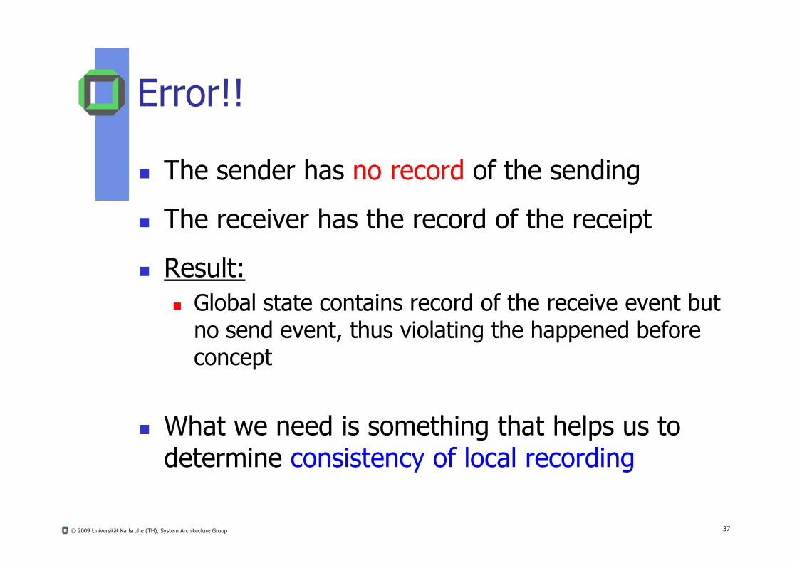
Error!!
The sender has no record of the sending
The receiver has the record of the receipt
Result:
37
Global state contains record of the receive event but no send event, thus violating the happened before concept
What we need is something that helps us to determine consistency of local recording
© 2009 Universität Karlsruhe (TH), System Architecture Group
Page 38
NotionNotion of of ConsistencyConsistency
38© 2009 Universität Karlsruhe (TH), System Architecture Group
Page 39
The Notion of Consistency
A global state is consistent if it could have been observed by an external observer
If e e` then it is never the case that e` is
39
If e e then it is never the case that e is observed by the external observer and not e
All feasible states are consistent
© 2009 Universität Karlsruhe (TH), System Architecture Group
Page 40
An Example
p q
40
p
q
Sp0 Sp
1 Sp2 Sp
3
Sq0 Sq
1 Sq2 Sq
3
m1
m2
m3
© 2009 Universität Karlsruhe (TH), System Architecture Group
Page 41
A Consistent State?
p q
Sp1 Sq
1
41
p
q
Sp0 Sp
1 Sp2 Sp
3
Sq0 Sq
1 Sq2 Sq
3
m1
m2
m3
© 2009 Universität Karlsruhe (TH), System Architecture Group
Page 42
Yes
p q
Sp1 Sq
1
42
p
q
Sp0 Sp
1 Sp2 Sp
3
Sq0 Sq
1 Sq2 Sq
3
m1
m2
m3
© 2009 Universität Karlsruhe (TH), System Architecture Group
Page 43
A Consistent State?
p q
Sp2 Sq
3
m3
43
p
q
Sp0 Sp
1 Sp2 Sp
3
Sq0 Sq
1 Sq2 Sq
3
m1
m2
m3
© 2009 Universität Karlsruhe (TH), System Architecture Group
Page 44
Yes
p q
Sp2 Sq
3
m3
44
p
q
Sp0 Sp
1 Sp2 Sp
3
Sq0 Sq
1 Sq2 Sq
3
m1
m2 m3
© 2009 Universität Karlsruhe (TH), System Architecture Group
Page 45
An Inconsistent State
p q
Sp1 Sq
3
45
p
q
Sp0 Sp
1 Sp2 Sp
3
Sq0 Sq
1 Sq2 Sq
3
m1
m2
m3
© 2009 Universität Karlsruhe (TH), System Architecture Group
Page 46
Why Consistent Global State?
How to combine information from multiple nodes, that the sampling reflects a global consistent state?
Problem:
Global States
© 2009 Universität Karlsruhe (TH), System Architecture Group 46
Local view is not sufficient
Global view:
We need messages transfers to the other nodes in order to collect their local states
Meanwhile these local states can change again
Page 47
Local History
N processes Pi, P := {P1, P2, ... Pn}, for each Pi: On a separate node ni Event series = history hi := <ei,1, ei,2, ... > May be finite or not
Observing a local history hi up to event ei k you get:
Global States
© 2009 Universität Karlsruhe (TH), System Architecture Group 47
Observing a local history hi up to event ei,k you get:prefix of history hi,k := < ei,1, ei,2, ... , ei,k >
Each ei,k is either a local or a communication event
Process state: State of Pi immediately before ei,k denoted si,k
State si,k records all events included in history hi,k-1 Hence, si,0 refers to Pi ‘s initial state
Page 48
Global History and Global State
Global States
Global history h := h1 h2 ... hn-1 hn
Similarly we can combine a set of local states to form a global state S := (s1, s2, … sn)
© 2009 Universität Karlsruhe (TH), System Architecture Group 48
However, which combination of local states is consistent?
Page 49
Cuts
Global States
Similar to the global state, we can define cuts based on k-prefixes:
C := h1,c1 h2 ,c2 ... hn-1,cn-1 hn,cn
h1 c1 is history up to and including event e1 c1
© 2009 Universität Karlsruhe (TH), System Architecture Group 49
1,c1 y p g 1,c1
The cut C corresponds to the state
S = (s1,c1+1, s2,c2+1, … sn,cn+1)
The final events in a cut are its frontier or its border line :
BL = {ei,ci | i {1,2, …n}}
Page 50
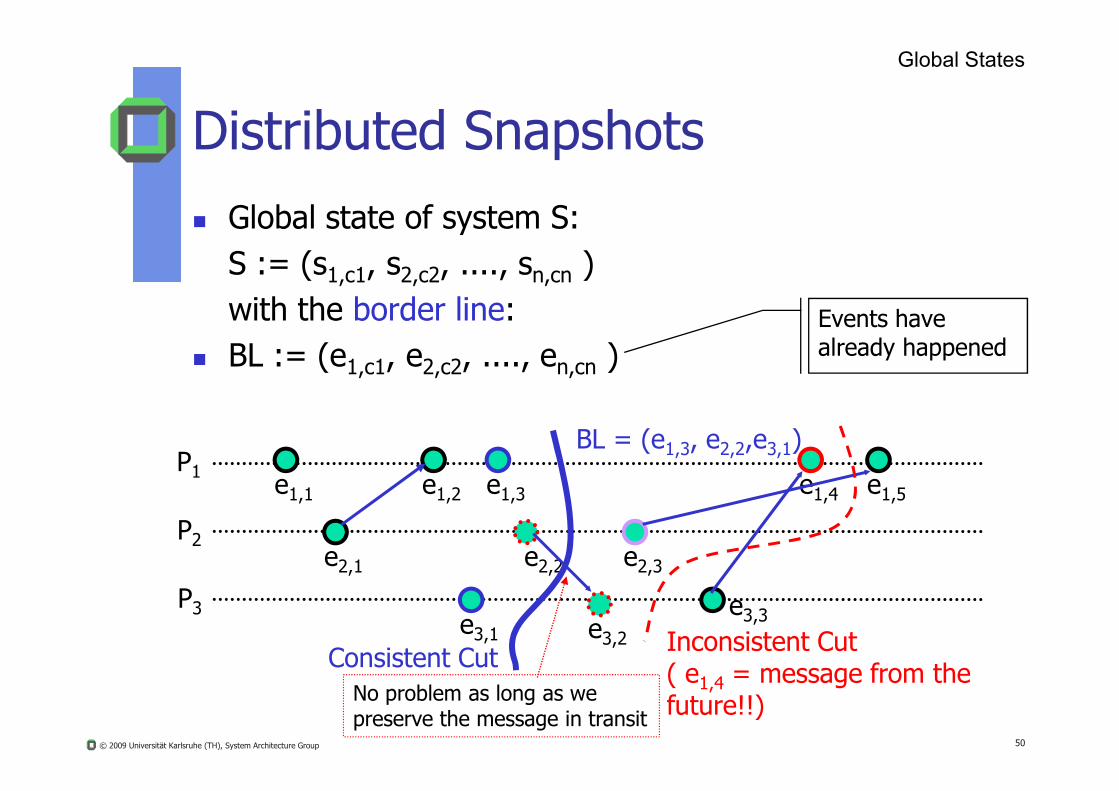
Distributed Snapshots Global state of system S:
S := (s1,c1, s2,c2, ...., sn,cn ) with the border line:
BL := (e1,c1, e2,c2, ...., en,cn ) Events have already happened
Global States
© 2009 Universität Karlsruhe (TH), System Architecture Group 50
P1
P2
P3
e1,1
e2,1
e1,2
e3,1
e1,3
e2,2
e3,2
e2,3
e3,3
e1,4 e1,5
BL = (e1,3, e2,2,e3,1)
Consistent Cut Inconsistent Cut( e1,4 = message from the future!!)No problem as long as we
preserve the message in transit
Page 51
Consistent Cuts
We call a cut C consistent iff for all events e’ C: e → e’ implies e C
A global state is consistent if it corresponds to
Global States
© 2009 Universität Karlsruhe (TH), System Architecture Group 51
A global state is consistent if it corresponds to a consistent cut
Remark: We can characterize the execution of a system as
a sequence of consistent global states
Page 52
Linearization
A global history that is consistent with the “happened before” relation is also called a linearization or consistent run
Global States
© 2009 Universität Karlsruhe (TH), System Architecture Group 52
A linearization only passes through consistent global states
A state S’ is reachable from state S’ if a linearization that passes through S and S’
Page 53
Distr. Distr. SnapshotSnapshot AlgorithmAlgorithm((Chandy/LamportChandy/Lamport))
Features:Does not promise us to give us exactly what is thereBut gives us consistent state!!
53© 2009 Universität Karlsruhe (TH), System Architecture Group
Page 54
Brief Sketch of the Algorithm
p sends a marker message along all its outgoing channels after it records its state and before it sends any other messages.
On receipt of a marker message from input channel cif h t t d d it t t
54
if p has not yet recorded its process state record the local process state state ( c ) = EMPTY
else state ( c ) = messages received on c since it had
recorded its state excluding the marker.
© 2009 Universität Karlsruhe (TH), System Architecture Group
Page 55
Chandy/Lamport Algorithm1
Global States
Requirements:
1. No process failures, no message losses
2. Sequence of received messages is the same as sequence of sent messages
3 d l h l h C S
© 2009 Universität Karlsruhe (TH), System Architecture Group 55
3. Bidirectional channels with FCFS property
4. Network is a strongly connected graph• From each process there is a connection path to each
other process
P2
P1 P3
Ch1
Ch2
Ch3
Ch4
1published 1985
Page 56
Chandy Lamport Algorithm (2)
Each process can initiate CLA to get a new global state
2 types of messages
marker messagesli ti
© 2009 Universität Karlsruhe (TH), System Architecture Group 56
application messages
First marker message is for saving local process state
Next marker messages are for saving the other input channel states
Page 57
Principle of Operation
Global States
Initially broadcast a marker message that contains a unique snapshot id (e.g. initiator id + sequence #) in order to differ from concurrent snapshot initializations
Process Q receiving a marker message for the first f h l
© 2009 Universität Karlsruhe (TH), System Architecture Group 57
time from input channel ic: If not yet done, records its local process state Define input channel state ic = EMPTY Q sends the marker message to all its other output channels Continue with the local application process Each received application message is queued in its
corresponding message queue
Page 58
Principle of Operation
Global States
Process Q receiving the marker message at another input channel CHi Terminates collection of messages at message queue MQi
Save and records state(CHi) to local state of Q If all incoming channels of Q have been saved and recorded
© 2009 Universität Karlsruhe (TH), System Architecture Group 58
If all incoming channels of Q have been saved and recorded, send aggregated local state of Q with all its input channels states to the initiator of the CLA
Page 59
Chandy/Lamport (1)
Input Channels Output Channels
Local State
© 2009 Universität Karlsruhe (TH), System Architecture Group 59
Pi
disk
Page 60
Chandy/Lamport (2)
Input Channels Output Channels
Local State
© 2009 Universität Karlsruhe (TH), System Architecture Group 60
Pi
disk
Application messages
Page 61
Chandy/Lamport (3)
Pi
Input Channels Output ChannelsLocal State
j
jFirstmarker
j
j
© 2009 Universität Karlsruhe (TH), System Architecture Group 61
diskApplication message j Marker message fromInitiator Pj
j j
Current state ofPi input channels
Application messages not belonging to current snapshot
Page 62
Chandy/Lamport (4)
Pi
Input Channels Output ChannelsLocal State
j
© 2009 Universität Karlsruhe (TH), System Architecture Group 62
diskApplication message j Marker message
j Lastmarker
Send snapshot message of Pito the initiator processvia appropriate output channel
Page 63
Algorithm in Action
p Sp0 Sp
1 Sp2 Sp
3
63
qSq
0 Sq1 Sq
2 Sq3
m1 m2 m3
© 2009 Universität Karlsruhe (TH), System Architecture Group
Page 64
Algorithm in Action
p Sp0 Sp
1 Sp2 Sp
3
q records state as Sq1 , sends marker to p
64
qSq
0 Sq1 Sq
2 Sq3
m1 m2 m3
© 2009 Universität Karlsruhe (TH), System Architecture Group
Page 65
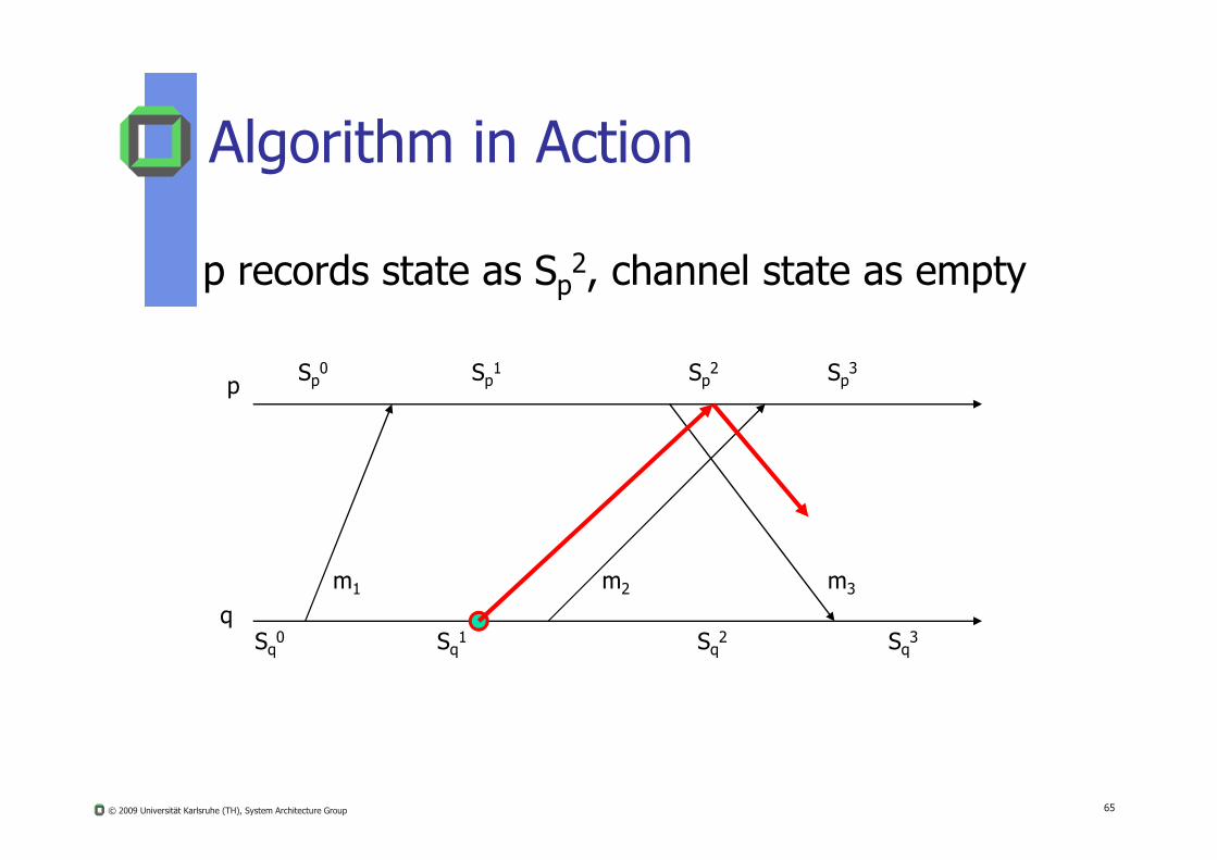
Algorithm in Action
p Sp0 Sp
1 Sp2 Sp
3
p records state as Sp2, channel state as empty
65
qSq
0 Sq1 Sq
2 Sq3
m1 m2 m3
© 2009 Universität Karlsruhe (TH), System Architecture Group
Page 66
Algorithm in Action
p Sp0 Sp
1 Sp2 Sp
3
q records channel state as m3
66
qSq
0 Sq1 Sq
2 Sq3
m1 m2 m3
© 2009 Universität Karlsruhe (TH), System Architecture Group
Page 67
Algorithm in Action
p Sp0 Sp
1 Sp2 Sp
3
Recorded Global State = ((Sp2, Sq
1), (0,m3) )
67
qSq
0 Sq1 Sq
2 Sq3
m1 m2 m3
Comment: Although application message m2 has been received in the meanwhile, this message does not belong to the global state initiated by q
© 2009 Universität Karlsruhe (TH), System Architecture Group
Page 68
Properties: Recorded Global State
If Si and Sj are the real global state when Lamport’s algorithm started and finished respectively and S* is the state recorded by the algorithm then,
68
S* is reachable from Si
Sj is reachable from S*
© 2009 Universität Karlsruhe (TH), System Architecture Group
Page 69
Still what good is it?
Stable Properties A property SP is called a stable property iff for all
states S’ reachable from S
69
SP(s) → SP(S’)
eg: deadlock, termination, token loss
© 2009 Universität Karlsruhe (TH), System Architecture Group
Page 70
Stable Properties
70
Si
Sj
S*
© 2009 Universität Karlsruhe (TH), System Architecture Group
Page 71
Stable Properties
71
Si
Sj
S*
© 2009 Universität Karlsruhe (TH), System Architecture Group
Page 72
Detection of Stable Properties
Outcome = false;while ( outcome == false ){
determine Global State S;
72
determine Global State S;outcome = SP(S);
}
© 2009 Universität Karlsruhe (TH), System Architecture Group
Page 73
Checkpointing
S* serves as a checkpoint
On a failure, restart th t ti
73
the computation from S*
Problem! Not able to restore to
Sj
Si
Sj
S*
© 2009 Universität Karlsruhe (TH), System Architecture Group
Page 74
Solution: Publishing
A Broadcast medium A central recorder process records all the
messages received by each process
74
messages received by each process Processes record their states at their own
time and send it to the recorder
© 2009 Universität Karlsruhe (TH), System Architecture Group
Page 75
Architecture of Publishing
75
recorder Sp1 Sq1
STATE SENTID
MSGSRECD
p Sp1
q Sq1
p q
© 2009 Universität Karlsruhe (TH), System Architecture Group
Page 76
q sends the message
m1
76
recorder Sp1 Sq2
p qSTATE SENT
IDMSGSRECD
p Sp1
q Sq1 1
© 2009 Universität Karlsruhe (TH), System Architecture Group
Page 77
p sends an ack recorder records m1
77
recorder Sp2 Sq2
p qSTATE SENT
IDMSGSRECD
p Sp1 m1
q Sq1 1
© 2009 Universität Karlsruhe (TH), System Architecture Group
Page 78
Determining Global State
Recorder can construct global state from Checkpointed States of all processes
78
Plus
Messages recd since last checkpoint
© 2009 Universität Karlsruhe (TH), System Architecture Group
Page 79
Problems
Publishing keeps track of all messages received by each process
Expensive! Solution
79
Solution recorder takes checkpoint of process p at time t deletes all messages recd by p before t.
© 2009 Universität Karlsruhe (TH), System Architecture Group
Page 80
p checkpoints
80
recorder Sp2 Sq2
p qSTATE SENT
IDMSGSRECD
p Sp1 m1
q Sq1 1
© 2009 Universität Karlsruhe (TH), System Architecture Group
Page 81
Recorder stores Sp2deletes m1
81
recorder Sp2 Sq2
p qSTATE SENT
IDMSGSRECD
p Sp2
q Sq1 1
© 2009 Universität Karlsruhe (TH), System Architecture Group
Page 82
The initial situation
82
recorder Sp2 Sq2
p qSTATE SENT
IDMSGSRECD
p Sp1 m1
q Sq1 1
© 2009 Universität Karlsruhe (TH), System Architecture Group
Page 83
Say p crashes
83
recorder Sq2
p qSTATE SENT
IDMSGSRECD
p Sp1 m1
q Sq1 1
© 2009 Universität Karlsruhe (TH), System Architecture Group
Page 84
Recorder reinstates p to Sp1
84
recorder Sq2
p q
Sp1
STATE SENTID
MSGSRECD
p Sp1 m1
q Sq1 1
© 2009 Universität Karlsruhe (TH), System Architecture Group
Page 85
Replays back m1
m1
85
recorder Sq2
p q
Sp2
STATE SENTID
MSGSRECD
p Sp1 m1
q Sq1 1
© 2009 Universität Karlsruhe (TH), System Architecture Group
Page 86
q crashes
86
recorder
p q
Sp2
STATE SENTID
MSGSRECD
p Sp1 m1
q Sq1 1
© 2009 Universität Karlsruhe (TH), System Architecture Group
Page 87
Recorder reinstates q to Sq1
87
recorder
p q
Sp2
STATE SENTID
MSGSRECD
p Sp1 m1
q Sq1 1
Sq1
© 2009 Universität Karlsruhe (TH), System Architecture Group
Page 88
Ignore m1
m1
88
recorder
p q
Sp2
STATE SENTID
MSGSRECD
p Sp1 m1
q Sq1 1
Sq1
© 2009 Universität Karlsruhe (TH), System Architecture Group
Page 89
Comparison
SNAPSHOT PUBLISHINGNetwork Strongly Need not be
89
Network connected Need not be
Mode Distributed Centralized
Scalability Yes No
Restorability No Yes
© 2009 Universität Karlsruhe (TH), System Architecture Group
Page 90
Summary
Global state detection is difficult in DSs
Chandy/Lamport’s snapshot algorithm may not give an actual state but is very helpful in d t ti t bl ti
90
detecting stable properties
Publishing gives an asynchronous way of determining global states but is not realy scalable
© 2009 Universität Karlsruhe (TH), System Architecture Group
Page 91
Mutual ExclusionMutual Exclusion
Centralized AlgorithmDecentralized AlgorithmToken Ring AlgorithmDistributed Algorithm
© 2009 Universität Karlsruhe (TH), System Architecture Group 91
Page 92
Mutual Exclusion in Local OS
Well known problem in multitasking OSes, e.g. access to shared memory, e.g.
Buffers
Global variables …
h d
© 2009 Universität Karlsruhe (TH), System Architecture Group 92
access to shared resources
access to shared data
various centralized mechanisms to ensure mutual exclusion, e.g. Semaphores
Monitors
Spin locks
Page 93
No StarvationNo deadlock
Requirements: Mutual Exclusion Requirements for a valid solution:
1. Safety: At most one process allowed to be in the CS
2. Liveliness (bounded Waiting): Each competitor must enter or exit its CS after some finite waiting time
3 Fair Ordering: Waiting in front of a CS is handled according to
Mutual Exclusion
© 2009 Universität Karlsruhe (TH), System Architecture Group 93
3. Fair Ordering: Waiting in front of a CS is handled according to FCFS
4. Progress: Length on RS does not influence the protocol in front of a CS
5. Portability: Hard to achieve in a DS
6. Fault tolerance: We assume that messages are delivered correctly, e.g. only once and after some finite delay
Page 94
Number of needed messages per critical section CS, minimal nm
Protocol delay (to evaluate who is the next) per CS, minimal dLast node leaves CS Next node enters CS
Protocol delay
time
Performance CriteriaMutual Exclusion
© 2009 Universität Karlsruhe (TH), System Architecture Group 94
Turnaround time TTCS, time interval between requesting to entera CS and leaving the CS, minimal TTCS
Throughput TPCS, # passing a CS per time unit (maximize TPCS)TPCS = 1/(d + ECS)
Node requests CS Node leaves CStime
Node enters CS
Execution time ECSTurnaround time TTCS
Page 95
Centralized Lock ManagerCentralized Lock Manager
© 2009 Universität Karlsruhe (TH), System Architecture Group 95
Page 96
Centralized Lock Manager CLM
A specific process CLM per critical region is designated to be the lock manager for all competing application clients
CLM controls accesses to CR using a grant token representing permission to enter
Mutual Exclusion
© 2009 Universität Karlsruhe (TH), System Architecture Group 96
p g p
To enter its CS, a client sends a request message to the CLM awaiting a positive answer from the CLM
If no client has the token, CLM replies immediately with the grant token. Otherwise CLM queues this request
Leaving the CS the client sends the grant token back to the CLM
Page 97
A Centralized AlgorithmMutual Exclusion
© 2009 Universität Karlsruhe (TH), System Architecture Group 97
a) P1 asks CLM (P3) for permission to enter its CR granted
b) P2 asks permission to enter same CR. CLM does not reply.
c) When P1 exits its CR, it notifies CLM that grants access to P2
Page 98
Client Client Client
request requestrequest “token granted”
Token holder
Problems with Centralized Locking?Mutual Exclusion
© 2009 Universität Karlsruhe (TH), System Architecture Group 98
CLM = Centralized Lock Manager
request request
queueIf CLM crashes uncertain state of CLM
1. A client might still hold the token2. Client has sent token, but token
was not yet received at CLM3. The CLM has the token4. How long would you wait, before
electing a new CLM?
Page 99
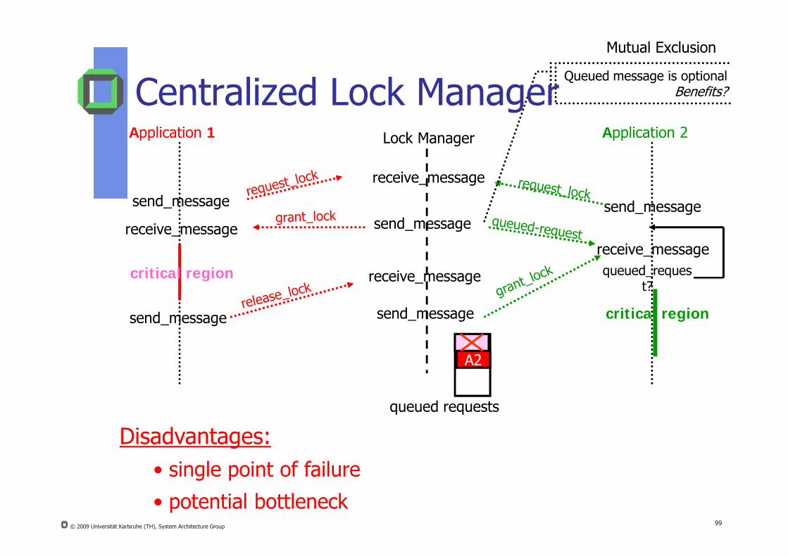
Application 1 Application 2Lock Manager
send_message
receive_message
send_messagereceive_message
critical region
send_message
receive_messagequeued_requesreceive message
Queued message is optionalBenefits?Centralized Lock Manager
Mutual Exclusion
© 2009 Universität Karlsruhe (TH), System Architecture Group 99
queued requests
A1
g
A2
send_message
t?
critical region
receive_message
send_message
Disadvantages:• single point of failure
• potential bottleneck
Page 100
Summary on CLM
Easy to implement Scalability? Bottleneck? Safety fulfilled Liveliness fulfilled
F i d i t f lfill d With t dditi l
Mutual Exclusion
© 2009 Universität Karlsruhe (TH), System Architecture Group 100
Fair ordering not fulfilled: Without additional requirements concerning the network, request are not served in FCFS order Adding logical time stamps per request might improve the
situation, but still does not solve fair ordering
Progress is fulfilled Fault tolerance: CLM might fail
Elect a new CLM (see election algorithms)
Page 101
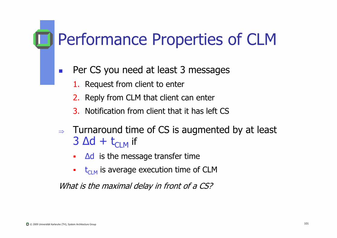
Performance Properties of CLM
Per CS you need at least 3 messages1. Request from client to enter
2. Reply from CLM that client can enter
3. Notification from client that it has left CS
© 2009 Universität Karlsruhe (TH), System Architecture Group 101
Turnaround time of CS is augmented by at least 3 Δd + tCLM if Δd is the message transfer time
tCLM is average execution time of CLM
What is the maximal delay in front of a CS?
Page 102
Decentralized AlgorithmDecentralized Algorithm
Lin’s Voting Algorithm in DHT DS.“A Practical Distributed Mutual Exclusion
Protocol in Dynamic P2P Systems”
Study of your one
© 2009 Universität Karlsruhe (TH), System Architecture Group 102
Page 103
Decentralized Mutual Exclusion
Principle: n lock manager per CS (resource), i.e. the resources are replicated and each replica has its own lock manager
A client can only access a resource if the majority of the n lock managers have sent a grant reply
© 2009 Universität Karlsruhe (TH), System Architecture Group 103
g g p y
Each lock manager responds ”immediately” to a client’s request with grant or deny
A client receiving a deny will retry again soon after
When a lock manager crashes, it will recover quickly, but will have forgotten about permission it had granted in the past
Page 104
Decentralized Mutual Exclusion
Lin et al. showed that it is quite robust
However, under heavy load, i.e. high concurrency in front of the CS (resources) no client will get the majority of the n lock
© 2009 Universität Karlsruhe (TH), System Architecture Group 104
client will get the majority of the n lock managers, thus resulting in a poor performance
Page 105
Algorithms based on Logical Algorithms based on Logical StructuresStructures
Token Ring Tree Structured
© 2009 Universität Karlsruhe (TH), System Architecture Group 105
Page 106
Token Ring AlgorithmMutual Exclusion
© 2009 Universität Karlsruhe (TH), System Architecture Group 106
a) A group of processes on a network à la Ethernet
b) A logical ring (constructed in software)
Page 107
Token-Passing Mutual ExclusionMutual Exclusion
The token-passing algorithm: A process can enter its CS iff it is the current owner
of the access token
When leaving its CS, the owner of the access token
© 2009 Universität Karlsruhe (TH), System Architecture Group 107
g ,sends this token to its immediate successor
Observation:In times when no participant wants to enter its CS, nevertheless the access token is circulating within the logical ring reducing the bandwidth of the network overhead
Page 108
Logical Ring
Current
Standard Token AlgorithmMutual Exclusion
Given a lattice of nodes:
© 2009 Universität Karlsruhe (TH), System Architecture Group 108
Token Holder
Processes waiting in front of their critical
sections CS request are not served
according to FCFS
t1t0
Page 109
Check out the list of requirements:
1. Safety, yes, due to unique token, only token holder may enter its CS
2. Liveliness, yes, as long as logicalring has a finite number of nodes
Mutual Exclusion
Analysis of Token Based Exclusion
© 2009 Universität Karlsruhe (TH), System Architecture Group 109
ring has a finite number of nodes
3. Sequence order, no, TLM maychange the internal order of thewaiting requests
4. Fault tolerance?• splitting of the logical ring
and you might be lost.• losing the token
Page 110
Problems with Token-AlgorithmMutual Exclusion
1. How to distinguish if the token has been lost or if it is used very long?
2. What happens if token-holder crashes for some time and recovers later on?
© 2009 Universität Karlsruhe (TH), System Architecture Group 110
3. How to maintain a logical ring if a participant drops out (voluntarily or by failure) of the system?
4. How to identify and add new participants?
5. Ring imposes an average delay of N/2 hops limiting scalability
Page 111
Receive(“Token” from Node i-1)
Participant on Node i
Receive(“Token” from Node i)
Participant on Node i +1
Implementation IssuesMutual Exclusion
© 2009 Universität Karlsruhe (TH), System Architecture Group 111
Send(“Token” to Node i+1)
Critical Section
Send(“Token” to Node i+2)
Critical Section
Page 112
Implementation Issues
Receive(“Token” from Node i-1)
Participant on Node i
Receive(“Token” from Node i)
Participant on Node i +1
Mutual Exclusion
© 2009 Universität Karlsruhe (TH), System Architecture Group 112
Send(“Token” to Node i+1)
Critical Section
Send(“Token” to Node i+2)
Critical Section
Page 113
Receive(“Token” from Node i-1)
Participant on Node i
Receive(“Token” from Node i)
Participant on Node i +1
Mutual Exclusion
Implementation Issues
© 2009 Universität Karlsruhe (TH), System Architecture Group 113
Send(“Token” to Node i+1)
Critical Section
Send(“Token” to Node i+2)
Critical Section
Question: What may happen if you try to give token to immediate successor?
Page 114
Receive(“Token” from Nodei-1)
Participant on Node i
Critical Section
Receive(“Token” from Nodei)
Participant on Node i +1
Critical Section
?
Prob 1
Mutual Exclusion
Implementation Issuess
© 2009 Universität Karlsruhe (TH), System Architecture Group 114
Send(“Token” to Nodei+1)
C t ca Sect o
Send(“Token” to Node i+2)
Critical Section
Question: How to solve this problem as a system architect?
Page 115
Send_Request(“Token” for CrS_1)
Participant on Node i +1
Prob 1
A token-handler-thread per application and critical section
Receive(“Token” from Nodei)
TokenHandler Node i +1
R i (L l R t) N bl ki
Implementation of a System Architect
Mutual Exclusion
© 2009 Universität Karlsruhe (TH), System Architecture Group 115
Send_Release(“Token” for CrS_1)
Critical Section_1
Send(“Token” to Node i+2)
If Local_Request ?yes
Receive(Local_Request)Receive(“Token” for CrS_1)
Receive(Local_Release)
Send(Local_Request)
no
Non blocking
Page 116
Performance of Token Ring Alg.
Suppose your logical token ring consists of p processes on p different nodes
Per CS you need at least 2 messages1. Token passing message from immediate predecessor
© 2009 Universität Karlsruhe (TH), System Architecture Group 116
2. Token passing message to immediate successor
Minimal turnaround time of CS is increased by 2 Δd Δd is the message transfer time
Average and maximal turn around times?
What about the requirements for a valid solution?
Page 117
Tree Based Token Algorithm
Set of processes can be structured as a rooted tree
Each node has a list for storing processes h h i i i l i
© 2009 Universität Karlsruhe (TH), System Architecture Group 117
that want to enter their critical sections
Initially all request lists are empty and the root contains the grant token
Lower nodes send their requests to the immediate predecessors
Page 118
Tree Based Mutual Exclusion (1)P1
P2 P3 P4
Token
© 2009 Universität Karlsruhe (TH), System Architecture Group 118
P6P5
Initially root P1 is the token holder
Page 119
Tree Based Mutual Exclusion (2)P1
P2 P3 P5P6
P4
Token
© 2009 Universität Karlsruhe (TH), System Architecture Group 119
P6
P6P5
Page 120
Tree Based Mutual Exclusion (3)P1 P3
P2 P3 P5P6
P4
Token
© 2009 Universität Karlsruhe (TH), System Architecture Group 120
P6
P6P5
Page 121
Tree Based Mutual Exclusion (4)P1 P3
P2 P3 P5P6
P4
Token
© 2009 Universität Karlsruhe (TH), System Architecture Group 121
P6
P6P5
Page 122
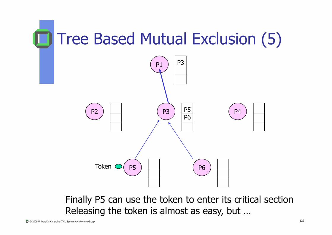
Tree Based Mutual Exclusion (5)P1 P3
P2 P3 P5P6
P4
© 2009 Universität Karlsruhe (TH), System Architecture Group 122
P6
P6P5Token
Finally P5 can use the token to enter its critical sectionReleasing the token is almost as easy, but …
Page 123
Performance of Tree Based Token?
Analyze in the tutorial
How to implement an as fair solution as possible avoiding unbounded waiting of sub-trees
© 2009 Universität Karlsruhe (TH), System Architecture Group 123
Problem: P3 in the example has no knowledge what’s going on in the other sub-trees
Where to collect needed information about the requests
Page 124
Distributed Mutual ExclusionDistributed Mutual Exclusion
Ricard Agrawala
Maekava
© 2009 Universität Karlsruhe (TH), System Architecture Group 124
Page 125
Distributed Lock ManagersMutual Exclusion
Two distinct solutions: Ricart/Agrawala consensus algorithm
All competitors have to agree upon the process that is allowed to enter its CS
Algorithm needs logical clocks
© 2009 Universität Karlsruhe (TH), System Architecture Group 125
g g
Ricart, G.; Agrawala, A.: “An optimal Algorithm for Mutual Exclusion in Computer Networks”, C.ACM, 1981
Maekawa’s voting algorithm Sufficient processes have to vote for one competitor
before it can enter its CS
M. Maekawa. "A Square-root(N) Algorithm for Mutual Exclusion in Decentralized Systems". ACM Transactions on Computer Systems, May 1985.
Page 126
Distributed Lock Managers
Assumptions:
N Processes have unique numeric identifiers They maintain totally ordered Lamport times
All processes have communication channels to all other processes
Mutual Exclusion
© 2009 Universität Karlsruhe (TH), System Architecture Group 126
processes
Reliable communication based on multicast Process requesting access multicasts its request to all other
N-1 processes
Process may only enter its CS when all other N-1 processes have replied an acknowledge message
No node failures
Page 127
Process States
Released, i.e. process doesn‘t need its CS at the moment
Wanted i e process wants to enter its CS
Mutual Exclusion
© 2009 Universität Karlsruhe (TH), System Architecture Group 127
Wanted, i.e. process wants to enter its CS
Held, i.e. process is in its CS
Page 128
Ricart Agrawala Algorithmenter():
state := WANTED;Multicast request to all peers;T := request’s Lamport timestamp;Wait until (N - 1) responses are received;state := HELD;
Mutual Exclusion
© 2009 Universität Karlsruhe (TH), System Architecture Group 128
On receipt of a request <T(i), P(i)> at P(j), ji:if( state == HELD or (state == WANTED and
(T, P(j)) < (T(i), P(i)) ) {Queue request without replying;
} else {Reply to P(i);
}
release():state := RELEASED;Respond to queued requests;
Page 129
Distributed Lock Manager (DLM) Mutual Exclusion
Three message types (2 are required, 1 is optional)
Request_Message
© 2009 Universität Karlsruhe (TH), System Architecture Group 129
Queued_Message
Grant_Message
Page 130
Request Message
A process wishing to enter its CS either
multicasts or
sends (n-1) times individually
Mutual Exclusion
© 2009 Universität Karlsruhe (TH), System Architecture Group 130
an according request message to all processes competing for the critical region
Each request message contains a “Lamport timestamp” and the PID of the requester total ordering
Page 131
Queued MessageMutual Exclusion
This type of message is only optional and is sent by recipients of the request message whenever the requestcannot be granted immediately, i.e.
recipient itself is currently in its CS or
© 2009 Universität Karlsruhe (TH), System Architecture Group 131
recipient itself is currently in its CS or
recipient had initiated an earlier request
Remark: This message type eases to find out whether suspected dead participants
Page 132
Grant MessageMutual Exclusion
Sent to a requesting process from all participants in two circumstances:
recipient is not in its CS and has no earlier request
© 2009 Universität Karlsruhe (TH), System Architecture Group 132
request
if recipient is in its CS
first, it queues the request
Later on when it leaves its CS it will send the grant message to the requester
Page 133
Release MessageMutual Exclusion
Having released the resource this message is sent to allparticipants with a queued request-message.
Another example for Java’s notify_all()
© 2009 Universität Karlsruhe (TH), System Architecture Group 133
Why is it not sufficient to notify just one of the waiting participants?
Page 134
Ricart-Agrawala AlgorithmMutual Exclusion
© 2009 Universität Karlsruhe (TH), System Architecture Group 134
a) 2 processes enter same CR at the same moment.
b) Process 0 has the lowest timestamp, so it wins.
c) When process 0 is done, it sends an OK also, process 2can now enter the critical region.
Page 135
Analysis of Ricart/Agrawala No tokens anymore
Cooperative voting to determine sequence of CSs
Does not rely on an interconnection media offering ordered messages
S i li ti b d l i l ti t (t t l
Mutual Exclusion
© 2009 Universität Karlsruhe (TH), System Architecture Group 135
Serialization based on logical time stamps (total ordering)
If client wants to enter CS it asks all others for permission and proceeds if all others have agreed
If a client C gets a permission request from another client C’ and if C is not interested in its CS, C returns permission immediately to the requester C’.
Page 136
Correctness Conditions (1)Mutual Exclusion
All nodes behave identically, thus we just have to regardnode xAfter voting, 3 groups of requests can be distinguished:
1 known at node x with time stamp less than C
© 2009 Universität Karlsruhe (TH), System Architecture Group 136
1. known at node x with time stamp less than Cx
2. known at x with a time stamp greater than Cx
3. those being still unknown at node x
Page 137
Correctness Conditions (2)
During this voting, marks may change accordingto the following conditions:
Condition 1: Requests of group 1 have to be served or they have to take a time stamp greater th C
Mutual Exclusion
© 2009 Universität Karlsruhe (TH), System Architecture Group 137
than Cx
Condition 2: Requests of group 2 may not get a time stamp smaller than Cx
Condition 3: Request of group 3 must have time stamps greater than Cx
Page 138
Two Phases of Voting Algorithm
1. Participants at node i willing to enter their CS send request messages ei to all other participants, whereei contains the actual Lamport time Li of node i.(After each send, node i increments its counter Ci).
Mutual Exclusion
© 2009 Universität Karlsruhe (TH), System Architecture Group 138
Result: If all permission messages have arrived at node i, the corresponding requester may enter its critical section.
Delay a bit
Cx := max{Cx,Ci +1}
2. All other participants return permission messages ai. Node x replies to a request message ei as soon as all older requests (received at earlier Lamport times) are completed.
Page 139
Node i
N d j
<eiMi>
Ci := max{Ci,M’k+1}delay permission ak
ai
Example of the Voting AlgorithmMutual Exclusion
© 2009 Universität Karlsruhe (TH), System Architecture Group 139
Suppose: Mi < Mk the request message Mi has a smaller time stamp than Mk,we have to delay the answer for the request message ek in node i !
Node j
Node kCk := max{Ck,Mi+1}
<ek,Mk> ak ak<ak,M’k>
Page 140
Summary
Instead of a single point of failure in the centralized solution, now each node is supposed not to fail
We need an efficient multi-cast and/or a group management
Mutual Exclusion
© 2009 Universität Karlsruhe (TH), System Architecture Group 140
In practice rarely used
Page 141
Algorithm #messages per CS
Delay d
Response time if CS is free
Potential Problems
Centralized 3 2T* 2T + E** Crash of central node
Decentralized 3mk 2m Starvation, low
Mutual Exclusion
Analysis of Mutual Exclusion Alg.
© 2009 Universität Karlsruhe (TH), System Architecture Group 141
efficiency
Standard Token
1 … (0 … n-1)*T (0,n-1)*T + E Loss of token, Crash of node
Ricard-Agrawala
2(n-1) 2(n-1)*T 2(n-1)T + E Crash of any node
* T: Message Transfer Time** E: Execution Time of CS
Page 142
Quorum based AlgorithmsQuorum based Algorithms
Maekawa Quorum Voting
© 2009 Universität Karlsruhe (TH), System Architecture Group 142
Page 143
Motivation
Major drawback of Ricard/Agrawala is its scalability problem, because every other member of the critical region has to agree before any P can enter its CS
Each P when about to leave its CS has to sent the
© 2009 Universität Karlsruhe (TH), System Architecture Group 143
release message to its N-1 partners
Furthermore, despite the message transfers overhead reliability is even less than in the centralized solution
Goal: Solution with fewer partners accepting a current request for entering a CS
Page 144
Maekawa’s Voting Approach
Observation: to get access, not all processes have to agree suffices to split set of processes up into subsets (voting sets)
that overlap suffices that there is consensus within every subset
© 2009 Universität Karlsruhe (TH), System Architecture Group 144
Model: processes p1, .., pN
voting sets V1, .., VN chosen such that i, k and for some integer M: pi Vi
Vi Vk (some overlap in every voting set) | Vi | = K (fairness: all voting sets have equal size) each process pk, is contained in M voting sets
Page 145
Maekawa’s CS-Protocol
Protocol: to obtain entry to CS, pi sends request messages to
all K-1 members of its voting set Vi
cannot enter until all K-1 replies received
when leaving CS send release messages to all
© 2009 Universität Karlsruhe (TH), System Architecture Group 145
when leaving CS, send release messages to all members of Vi
when receiving request message if state = HELD or already replied (voted) since last request
then queue request
else immediately send reply
when receiving release message remove request at head of queue and send reply
Page 146
Voting Algorithm (Maekawa)
On initializationstate := RELEASED;voted := FALSE;
For pi to enter the critical sectionstate := WANTED;Multicast request to all processes in Vi – {pi};Wait until (number of replies received = (K 1));
Mutual Exclusion
© 2009 Universität Karlsruhe (TH), System Architecture Group 146
Wait until (number of replies received = (K – 1));state := HELD;
On receipt of a request from pi at pj (i ≠ j)if (state = HELD or voted = TRUE)then
queue request from pi without replying; else
send reply to pi;voted := TRUE;
end if
Page 147
Voting Algorithm (Maekawa)
For pi to exit the critical sectionstate := RELEASED;Multicast release to all processes in Vi – {pi};
On receipt of a release from pi at pj (i ≠ j)if (queue of requests is non-empty)then
Mutual Exclusion
© 2009 Universität Karlsruhe (TH), System Architecture Group 147
remove head of queue – from pk, say; send reply to pk;voted := TRUE;
elsevoted := FALSE;
end if
Each process only needs grants from all its potential voters
Page 148
Maekawa’s Properties
Optimization goal: minimize K while achieving mutul exclusion
Can be shown to be reached when K~(N) and M=K
© 2009 Universität Karlsruhe (TH), System Architecture Group 148
optimal voting sets: nontrivial to calculate
approximation: derive Vi so that | Vi | ~ 2* (N)
place processes in a N x N matrix
let Vi the union of the row and column containing pi
Page 149
Quorum Example (Grid Scheme)
P1 P2 P3 P4 P5
P6 P7 P8 P9 P10
© 2009 Universität Karlsruhe (TH), System Architecture Group 149
V13P11 P12 P13 P14 P15
P16 P17 P18 P19 P20
P21 P22 P23 P24 P25
Page 150
Properties of Maekawa
Satisfies mutual exclusion if possible for two processes to enter critical section, then
processes in the non-empty intersection of their voting sets would have both granted access
impossible, since all processes make at most one vote after receiving request
© 2009 Universität Karlsruhe (TH), System Architecture Group 150
receiving request
However, deadlocks are possible consider three processes with
V1 = {p1, p2}, V2 = {p2, p 3}, V3 = {p3, p1}
possible to construct cyclic wait graph
p1 replies to p2, but queues request from p3
p2 replies to p3, but queues request from p1
p3 replies to p1, but queues request from p2
Page 151
Variations
Maekawa’s algorithm can be modified to ensure absence of deadlocks use of logical clocks processes queue requests in happened-before order means that ME3 is also satisfied
© 2009 Universität Karlsruhe (TH), System Architecture Group 151
Performance bandwidth utilization
2 N per entry, N per exit, total 3 N is better than Ricart and Agrawala for N>4
client delay same as for Ricart and Agrawala
synchronization delay round-trip time instead of single-message transmission
time in Ricart and Agrawala
Page 152
Comments on Fault Tolerance
None of these algorithms tolerates message loss
Ring-algorithms can not tolerate single crash failure
Maekawa’s algorithm can tolerate some crash failure if process is in a voting set not required, rest of the system
not affected
© 2009 Universität Karlsruhe (TH), System Architecture Group 152
not affected
Central-Server: tolerates crash failure of node that has neither requested access nor is currently in the critical section
Ricart and Agrawala algorithm can be modified to tolerate crash failures by the assumption that a failed process grants all requests immediately requires reliable failure detector
Page 153
ElectionElection
Traditional ElectionElections in Wireless EnvironmentsElections in Large-Scale Systems
© 2009 Universität Karlsruhe (TH), System Architecture Group 153
Page 154
When Elections?
Necessary when
System is booted in order to instantiate a
centralized coordinator for system activities
© 2009 Universität Karlsruhe (TH), System Architecture Group 154
centralized monitor to watch system’s state
At run-time when a serial server
fails or
retires
Page 155
Election Algorithms
Some distributed applications need one specific centralized process (task), acting as a
Coordinator, e.g. for centralized mutual exclusion manager
Monitor
Global States
© 2009 Universität Karlsruhe (TH), System Architecture Group 155
Monitor
Collector
…
Via election algorithms you can establish a new coordinator -if the old one has crashed
You need an agreement on the new coordinator
Page 156
Election
Global States
An election should fulfill the following requirements:
E0: Correctness: Only one process will be elected
E1: Safety: each process pi has the attribute
© 2009 Universität Karlsruhe (TH), System Architecture Group 156
electedi = null or
electedi = P,
whereby P is the live process with highest id at the end of the current election
E2: Liveness: each process pi eventually will have the attribute electedi ≠ null
Page 157
Election
Election Algorithms
Suppose, your centralized lock manager has crashed.How to do elect a new one in a DS?
two major election algorithms, both are based upon:
each process/node has a unique process/node number
© 2009 Universität Karlsruhe (TH), System Architecture Group 157
each process/node has a unique process/node number(i.e. there is a total ordering of all processes/nodes)
live process with highest process number of all active processes is the current (will b the next) coordinator
after a crash the restarting former process (eventually the previous coordinator) is put back to the set of active processes and the election is restarted again
Page 158
Election in a Logical Ring
Assumptions:
Processes (+nodes) have unique identifiers
Each process can communicate with all live
© 2009 Universität Karlsruhe (TH), System Architecture Group 158
a p o ss a o u a asuccessors on the ring
Processes can fail (stop responding to its environment); this failure can be detected
Page 159
Ring Algorithm (Le Lann, 1977)
Each process/node Ni knows all its successors, i.e. the complete logical ring
2 types of messages are used: election e: to elect the new coordinator
coordinator c: to introduce coordinator to the nodes
Election
© 2009 Universität Karlsruhe (TH), System Architecture Group 159
coordinator c: to introduce coordinator to the nodes
Algorithm is initiated by any node Ni suspecting that the current coordinator no longer works
Ni send a message e with its node number i to its immediate successor Ni+1
If this immediate successor Ni+1 does not answer, it is assumed thatNi+1 has crashed and the e is sent to Ni+2, …
Page 160
Ring Algorithm
Ni receives an e/c-message with a list of node numbers:
If an e-message does not contain its process/node number i, Ni adds it to the list, sends e-message to Ni+1
If an e-message contains its node number i, this e-message has circled the ring of all active nodes The
Election
© 2009 Universität Karlsruhe (TH), System Architecture Group 160
message has circled the ring of all active nodes. The highest process/node number in the list is the new coordinator and Ni converts e-message into a c-message
If its an c-message, Nj keeps in mind the node with the highest number in that list being the new coordinator
If a c-message has circled once, it’s deleted
After having restarted a crashed node you can use an “inquiry”-message, circling once around the ring
Page 161
4 5
63
4 5
63
(“e”,2)
(“e”,5)(“e”,2,3)
(“e”,5,6)
(“e”,2,3,4)
Ring Algorithm
Nodes 2 and 5 both initiate independently the
5
Election
© 2009 Universität Karlsruhe (TH), System Architecture Group 161
7
81
2
Actual coordinator crashes
8
7
81
2(“e”,5,6,7)
(“e”,5,6,7)
algorithm2
Page 162
4 5
63
(“e”,2,3,4)
(“e”,2,3,4,5)
(“e”,2,3,4,5,6)(“e”,5,6,7,1,2)
4 5
63(“e”,5,6,7,1,2,3)
(“e”,5,6,7,1,2,3,4)
Ring Algorithm
Election
© 2009 Universität Karlsruhe (TH), System Architecture Group 162
7
81
2
(“e”,5,6,7)
(“e”,5,6,7,1)
7
81
2
(“e”,2,3,4,5,6,7)
(“e”,2,3,4,5,6,7,1)
Both e-messages circled once around the ring of all active nodes
Page 163
4 5
63
(“c”,5,6,7,1,2,3,4)
(“c”,2,3,4,5,6,7,1)
Ring Algorithm
Election
© 2009 Universität Karlsruhe (TH), System Architecture Group 163
7
81
2 This coordinator-message circlesonce around the logical-ring,All nodes know that 7 is the new coordinator
Page 164
Improved Ring Algorithm
Assumptions:
Processes do not know each others PID
all nodes communicate on a uni directional
© 2009 Universität Karlsruhe (TH), System Architecture Group 164
all nodes communicate on a uni-directional ring structure, i.e. only with its successor
all processes have unique integer id
asynchronous, reliable system
Page 165
Improved Ring Algorithm Initially, all processes marked “non-participant” To start election, process place election message with own
identifier on ring and marks itself “participant” upon receipt of election message, compare received identifier
with own if received id greater than own id, forward message to neighbor if received id smaller than own id,
© 2009 Universität Karlsruhe (TH), System Architecture Group 165
if own status is “non-participant”, then substitute own id in election message and forward on ring
otherwise, do not forward message (already “participant”) if received id is identical to own id
this process’s id must be greatest and it becomes elected marks own status as “non-participant” sends out coordinator message
when receiving coordinator message mark own status as “non-participant” set attribute electedi appropriately and forward coordinator
message
Page 166
Improved Ring Algorithm1
9
4
317
24
1
Process has 2 possible states:• participating• not participating
Initially each p = not participating
Election message only contains PID of maximal passed process
© 2009 Universität Karlsruhe (TH), System Architecture Group 166
1Chang-Roberts 1979
24
15
28
1
Note: The election was started by process 17.Highest process identifier encountered so far is 24. Participant processes are shown darkened
Receiving process compares PID in election message with its own PID:
If (state = non participating andownPID > e(PID)) then
{ e(PID)=ownPIDstate = participating}
else …
Page 167
Analysis: Improved Ring Election
Properties E0 is satisfied, only one new coordinator
E1 satisfied, since all identifiers are compared
E2 follows from reliable communication property
© 2009 Universität Karlsruhe (TH), System Architecture Group 167
2 p p y
Performance at worst 2N-1 messages for electing the left-hand neighbor
another N coordinator messages
Failures tolerates no failures
Page 168
Election
Election by Bullying
Assumptions:
Network is synchronous
Nodes can crash, crashes will be detected reliably
© 2009 Universität Karlsruhe (TH), System Architecture Group 168
Fully connected network, no message loss
Crash failures only
Nodes have unique identifiers and know ids of all other nodes (else broadcast)
Page 169
Bully Algorithm1
Election
Goal: Find live node with the highest number, choose it as coordinator and tell this all other nodes
Start: Algorithm may start at any node, having recognized that previous coordinator is no longer responding.
© 2009 Universität Karlsruhe (TH), System Architecture Group 169
g p g
Message types:
Election e, initiating the election
Answer a, confirming the reception of an emessage
Coordinator c, telling all others, that it is the new coordinator
1Garcia-Molina, 1982
Page 170
Steps of Bully Algorithm
Election
1. Some node Ni sends e-messages to all other nodes Nj, j > i.
2. If there is no answer within t, Ni elects himself as coordinator sending this info via a c-message to all others Nj, j < i.
3. If Ni got an a-message within t (i.e. there is an active node with a higher number), it is awaiting another time-limit t’. It
© 2009 Universität Karlsruhe (TH), System Architecture Group 170
with a higher number), it is awaiting another time limit t . It restarts election, if there is no c-message within t’
4. If Nj receives an e-message from Ni, it answers with an a-message to Ni and starts the algorithm for itself (step 1).
5. If a node N -after having crashed and being restarted- is active again, it starts step 1.
6. Highest numbered node declares itself to be the newcoordinator
Page 171
e a
a TimeoutN
Node 1
Node 2
Node 3
Node 4
Example Bully Algorithm
Election
© 2009 Universität Karlsruhe (TH), System Architecture Group 171
Node 2 detects the false behavior of the coordinator
New coordinator
Node 4
Node 5
Current Coordinator has crashed
Nodes 3 and 4 have to start the algorithm due to their higher numbertelling node 2 to stop with its election algorithm
Page 172
Bully Algorithm (1)
Election
© 2009 Universität Karlsruhe (TH), System Architecture Group 172
(a) Process 4 starts an election(b) Process 5 and 6 respond, telling 4 to stop(c) Now 5 and 6 each start an election
Page 173
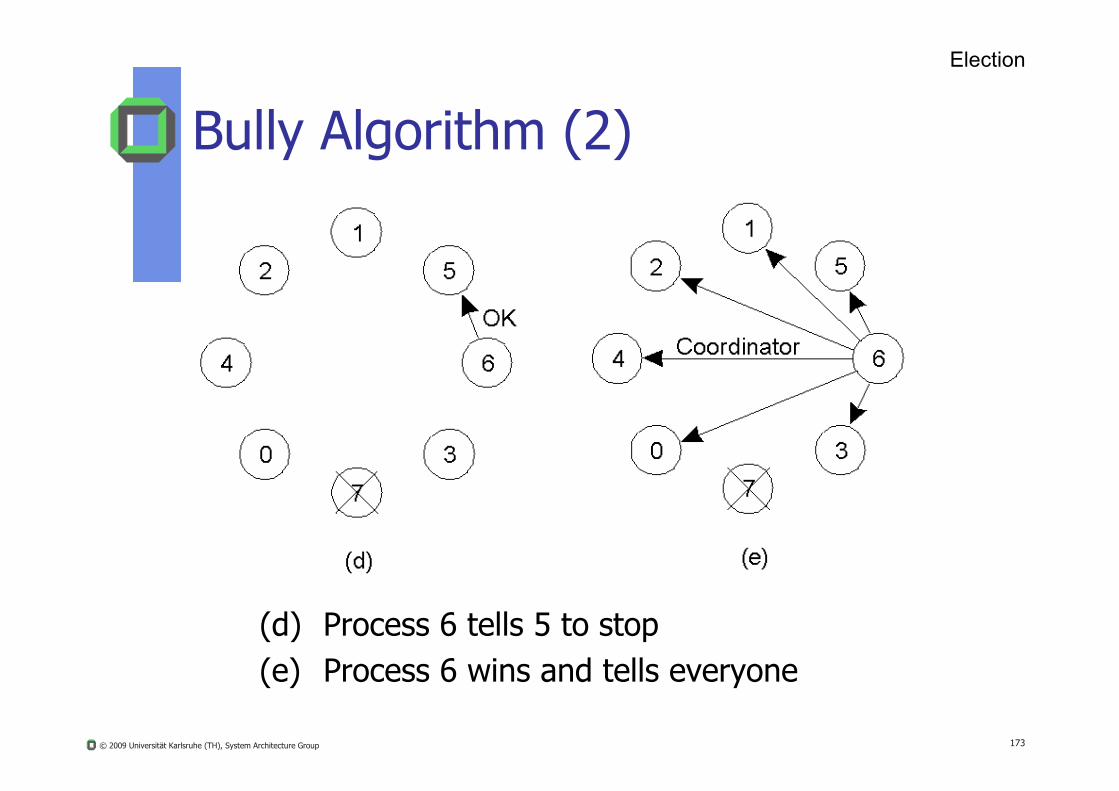
Bully Algorithm (2)
Election
© 2009 Universität Karlsruhe (TH), System Architecture Group 173
(d) Process 6 tells 5 to stop(e) Process 6 wins and tells everyone
Page 174
Analysis of Bully
Properties E0 is satisfied, only one new coordinator
E1 satisfied, since all identifiers are compared
E2 follows from reliable communication property
© 2009 Universität Karlsruhe (TH), System Architecture Group 174
Performance Best case: process p with second highest PID detects crash
of old coordinator
Elects itself coordinator and send N-2 election messages
Requires O(N2) messages in worst case when lowest process detects coordinator crash
N-1 processes with higher Ids start the election
Page 175
Algorithm Number of Messages
Time
Bully O(n2) O(n)
Election
Comparison of 2 Election Algorithms
© 2009 Universität Karlsruhe (TH), System Architecture Group 175
Ring 2(n-1) 2(n-1)
In M. Weber: “Verteilte Systeme” there is another election algorithm (from Mattern) based on a tree-topology
Page 176
Election In Wireless Election In Wireless EnvironmentsEnvironments
Wireless Ad Hoc Nets with non moving nodesVasudevan et al.: “Design and Analysis of a Leader Election Algorithm for Mobile Ad Hoc
Networks”, Proc. 12. International Conference on Network Protocols, 2004
http://www-net.cs.umass.edu/~svasu/pubs.html
© 2009 Universität Karlsruhe (TH), System Architecture Group 176
Page 177
Elections in Wireless Environ. (1)
© 2009 Universität Karlsruhe (TH), System Architecture Group 177
Election algorithm in a wireless network, with node a as the source. (a) Initial network. (b)–(e) The build-tree phase
Page 178
Elections in Wireless Environ. (2)
Figure 6-22. Election algorithm in a wireless network, with node a as the source. (a) Initial network. (b)–(e) The build-tree phase
© 2009 Universität Karlsruhe (TH), System Architecture Group 178
Page 179
Elections in Wireless Environ. (3)
Figure 6-22. (e) The build-tree phase. (f) Reporting of best node to source.
© 2009 Universität Karlsruhe (TH), System Architecture Group 179
Page 180
Elections in LargeElections in Large--Scale DSScale DS
Study of your own
© 2009 Universität Karlsruhe (TH), System Architecture Group 180
Page 181
Elections in Large-Scale Systems (1)
Requirements for superpeer selection:
1. Normal nodes should have low-latency access to superpeers.
2. Superpeers should be evenly distributed across the
© 2009 Universität Karlsruhe (TH), System Architecture Group 181
p p yoverlay network.
3. There should be a predefined portion of superpeers relative to the total number of nodes in the overlay network.
4. Each superpeer should not need to serve more than a fixed number of normal nodes.
Page 182
Superpeer Election
In a DHT system:Reserve a fixed part of the ID space for superpeers
Example:If s superpeers are needed for the DS that uses m
© 2009 Universität Karlsruhe (TH), System Architecture Group 182
If s superpeers are needed for the DS that uses m-bit identifiers, simply reserve k = log2S leftmost bits for superpeersWith n nodes we’ll have on average
2k-m *n superpeersRouting to superpeer: send message for key p to node responsible for p AND 11…1100…000
Page 183
Elections in Large-Scale Systems (3)
© 2009 Universität Karlsruhe (TH), System Architecture Group 183
Moving tokens in a two-dimensional space using repulsion forces
Page 184
Deadlock DetectionDeadlock Detection
© 2009 Universität Karlsruhe (TH), System Architecture Group 184
Page 185
Deadlocks
Outline
Deadlocks Deadlock Conditions Centralized Detections Path Pushing Distributed Detection
How to deal with deadlocks
© 2009 Universität Karlsruhe (TH), System Architecture Group 185
Transactions Transactions in Local systems Characteristic of Transactions Serializability Two Phase locking Protocol Distributed Transactions
How to support complicateddistributed applications
Page 186
Methods against Deadlocks in DS
Prevention (in some transaction oriented systems)
Avoidance (too complicated and time consuming)
Ignoring (still popular)
Deadlock Management
© 2009 Universität Karlsruhe (TH), System Architecture Group 186
g g ( p p )
Detecting (sometimes, if really needed) combined with repairing
Page 187
Deadlocks in Distributed Systems
In a DS a distinction is made between:
Resource deadlock: tasks are stuck waiting for resources held be each other
Deadlock Management
© 2009 Universität Karlsruhe (TH), System Architecture Group 187
Communication dl: tasks are stuck waiting formessage to arrive
However, message buffers ~ resources
Page 188
T1 holds x
• Using “locks” within transactions may lead to deadlocks:
T1 T2
…
T1 waits for y
Distributed Deadlocks
waitinggraph
Distributed Deadlocks
© 2009 Universität Karlsruhe (TH), System Architecture Group 188
T2 holds y…
lock(x)…
lock(y)
…….
lock(y)…
lock(x)time
T2 waits for x
A deadlock has occurred if global waiting graph contains a cycle.
Page 189
Deadlock Prevention
Deadlock Prevention
1. Task may hold only 1 resource at the same time (=> no cycles possible)
2. Pre-allocation of resources ( resource inefficiency)
© 2009 Universität Karlsruhe (TH), System Architecture Group 189
3. Release old resources if requesting a new one
4. Acquire in order (It’s quite a cumbersome task to number all resource types in a DS)
5. “Senior rule”: each application gets a “timestamp” (according to Lamport’s time).
Oldies (seniors) are preferred
Page 190
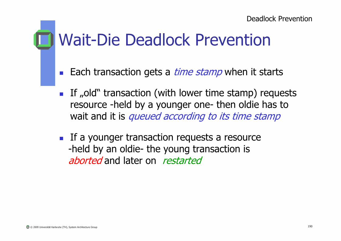
Wait-Die Deadlock PreventionDeadlock Prevention
Each transaction gets a time stamp when it starts
If „old“ transaction (with lower time stamp) requests resource -held by a younger one- then oldie has to wait and it is queued according to its time stamp
© 2009 Universität Karlsruhe (TH), System Architecture Group 190
q g p
If a younger transaction requests a resource -held by an oldie- the young transaction is aborted and later on restarted
Page 191
„Wait-Die“ Prevention
requester holder requester holder
wait
Deadlock Prevention
© 2009 Universität Karlsruhe (TH), System Architecture Group 191
Oldie (5) Kid (20) Kid (20) Oldie (5)wait
waits dies
Page 192
„Wound-Wait“ Prevention
requester holder requester holder
Deadlock Prevention
© 2009 Universität Karlsruhe (TH), System Architecture Group 192
Oldie (5) Kid (20) Kid (20) Oldie (5)
preempts waits
Page 193
Deadlock Avoidance
Deadlock Avoidance
Avoidance* in DS almost never used because:
1. Every node must keep track of global state of DS
substantial storage & communication overhead
© 2009 Universität Karlsruhe (TH), System Architecture Group 193
*Deadlock avoidance rarely used even in local systems
2. Checking for a global state safe must be mutual exclusive, otherwise two concurrent checks may violate the state safe
3. Checking for a global safe state requires substantial processing and communication
Page 194
Deadlock Detection
Deadlock Detection in DS
Increased problem: If there is a deadlock within a DS resources from different nodes may be involved
Several approaches:
© 2009 Universität Karlsruhe (TH), System Architecture Group 194
In any case: Deadlock must be detected within a finite amount of time
Several approaches:
1. Centralized Control
2. Hierarchical control
3. Distributed Control
Page 195
Deadlock Detection in DS
Correctness in a waiting-graph depends on:
progress
Deadlock Detection
© 2009 Universität Karlsruhe (TH), System Architecture Group 195
safety
Page 196
Deadlock Detection in DS
General remarks:
Message delay and out of date data may cause false cycles to be detected (phantom deadlocks)
Deadlock Detection
© 2009 Universität Karlsruhe (TH), System Architecture Group 196
After a “possible” deadlock has been detected, one has to double check if it is a real one
Having detected a deadlock, delete and restart task, if it‘s transaction oriented.
Page 197
Centralized Deadlock Detection
Local and global deadlock detector (LDD and GDD) (if a LDD detects a local deadlock it resolves it locally!).
The GDD gets status information from the LDD on waiting-graph updates
Deadlock Detection
© 2009 Universität Karlsruhe (TH), System Architecture Group 197
g g p p
periodically
on each request
If a GDD detects a deadlock involving resources at two or more nodes, it has to resolve this deadlock globally!)
Page 198
Centralized Deadlock Detection
Major drawbacks: The node hosting the GDD = point of single failure
“Phantom deadlocks” may arise because the global waiting graph is not up to date
Deadlock Detection
© 2009 Universität Karlsruhe (TH), System Architecture Group 198
global waiting graph is not up to date
Page 199
Centralized Deadlock Detection
Each node preserves its local waiting graph (respectively its resource usage graph)
Central coordinator preserve a global waiting graph (union of the local ones)
Deadlock Detection
© 2009 Universität Karlsruhe (TH), System Architecture Group 199
If coordinator detects a cycle it kills one task to break the deadlock
Problem: Does the global waiting graph correspond to the current global state?
Page 200
Phantom Deadlocks
Node 1 Node 2 Coordinator Node
A S S C A S C
Deadlock Detection
© 2009 Universität Karlsruhe (TH), System Architecture Group 200
B
R T
Question: B having released R, requests T, what may happen?
B
R T
How to solve? Using “Lamport time stamps“ per message
Page 201
Hierarchical Deadlock Detection
hierarchy of deadlock detectors (controllers)
waiting graphs (union of waiting graphs of children)
Deadlock Detection
© 2009 Universität Karlsruhe (TH), System Architecture Group 201
deadlocks resolved at lowest level possible
Page 202
Hierarchical Deadlock DetectionDeadlock Detection
© 2009 Universität Karlsruhe (TH), System Architecture Group 202
Each node in tree (except of a leaf node) keeps track of the resource allocation information of itself and of all “kids”
A deadlock that involves a set of resources will be detected by the node that is the common ancestor of all nodes whose resources are among the objects in conflict.
Page 203
Simple Distributed Deadlock Detection1
no global waiting-graph
deadlock detection cycle:
wait for information from other nodes
Deadlock Detection
© 2009 Universität Karlsruhe (TH), System Architecture Group 203
Remark: The non-local portion of the global waiting-graph is an abstract node “ex”
combine with local waiting-information
break cycles, if detected
share information on potential global cycles
1Obermark, 1982
Page 204
Situation on node x:
P1 P4
Some task outside node x waits for a resource currently owned by P4
Simple Distributed Deadlock Detection
Deadlock Detection
© 2009 Universität Karlsruhe (TH), System Architecture Group 204
P2 P3
No local deadlock
ex
Some task outside of node xholds a resource P3 is waiting for.
Page 205
Distributed Deadlock Detection1
A probe message <i, j, k> is sent whenever a task blocks
This probe message is sent along the edges of the
Deadlock Detection
© 2009 Universität Karlsruhe (TH), System Architecture Group 205
p g g gwaiting-graph if the recipient is waiting for a resource
If this probe message is sent to the initiating task, then there is a deadlock
1Chandy/Misra/Haas 1983)
Page 206
Distributed Deadlock DetectionDeadlock Detection
If P has to wait for resource R it sends a message to current resource-owner O
This message contains: PID of waiting task P
PID of sending task S
PID f i i t k E
© 2009 Universität Karlsruhe (TH), System Architecture Group 206
PID of receiving task E
Receiving process E checks, if E is also waiting. If so, it modifies the message: First component of message still holds
2. Component is changed to: PID(E)
3. Component is changed to PID of that process, process E is waiting for.
If message ever reaches waiting process P deadlock
Page 207
(0, 8, 0)
Example of DDD in DSDeadlock Detection
© 2009 Universität Karlsruhe (TH), System Architecture Group 207
P0 P1 P2
Node 1
P3
Node 2
P6 P8
Node 1
P4
P5 P7(0,2,3)
(0,4,6)
(0,5,7))(0,0,1) (0,1,2)
Page 208
Distributed Deadlock Detection
Recommended Reading:
Knapp, E.: Deadlock Detection in Distributed Databases, ACM Comp. Surveys, 1987
Si h P Di t ib t d O ti S t
Deadlock Detection
© 2009 Universität Karlsruhe (TH), System Architecture Group 208
Sinha, P.: Distributed Operating Systems: Concepts and Design, IEEE Computer Society, 1996
Galli, D.: Distributed Operating Systems: Concepts and Practice, Prentice Hall, 2000
Page 209
Deadlocks with Communication
1. Deadlocks may occur if each member of a specific group is waiting for a message of another member of the same group.
2. Deadlocks may occur due to unavailability of
Deadlock Detection
© 2009 Universität Karlsruhe (TH), System Architecture Group 209
2. Deadlocks may occur due to unavailability of message buffers etc.
3. Study for yourself: Read Stallings: Chapter 14.4., p. 615 ff
Page 210
Recommended Literaturehttp://link.springer-ny.com/link/service/series/0558/tocs/t2584.htm
A. Schiper, A.A. Shvartsman, H. Weatherspoon, B.Y. Zhao (Eds.): Future Directions in Distributed ComputingResearch and Position Papers (currently online available)
Part I: Foundations of DS: What to expect from theory?
© 2009 Universität Karlsruhe (TH), System Architecture Group 210
p y
Part II. Exploring Next-Generation Communication Infrastructures and Applications
Part III. Challenges in Distributed Information and Data Management
Part IV. System Solutions: Challenges and Opportunities in Applications of Distributed Computing Technologies