energies Review Electric Boosting and Energy Recovery Systems for Engine Downsizing Mamdouh Alshammari 1,2 , Fuhaid Alshammari 2 and Apostolos Pesyridis 1, * 1 Centre of Advanced Powertrain and Fuels (CAPF), Department of Mechanical, Aerospace and Civil Engineering, Brunel University London, Middlesex UB8 3PH, UK; [email protected]2 Department of Mechanical Engineering, University of Hai’l, Hail 55476, Saudi Arabia; [email protected]* Correspondence: [email protected]Received: 31 October 2019; Accepted: 4 December 2019; Published: 6 December 2019 Abstract: Due to the increasing demand for better fuel economy and increasingly stringent emissions regulations, engine manufacturers have paid attention towards engine downsizing as the most suitable technology to meet these requirements. This study sheds light on the technology currently available or under development that enables engine downsizing in passenger cars. Pros and cons, and any recently published literature of these systems, will be considered. The study clearly shows that no certain boosting method is superior. Selection of the best boosting method depends largely on the application and complexity of the system. Keywords: engine downsizing; electrically assisted turbocharger; electric supercharger; e-turbo; waste heat recovery; turbocharging; supercharging; turbocompounding; organic Rankine cycle 1. Introduction Although internal combustion engines are getting more efficient nowadays, still the major part of fuel energy is transformed into wasted heat. In terms of harmful exhaust emissions, the transportation sector is responsible for the one-third of CO 2 emissions worldwide and approximately 15% of the overall greenhouse gas emissions [1]. Moreover, owing to the limited amount of fossil fuels, prices fluctuate significantly, with consistent general rising trends, resulting in economic issues in non-oil-producing countries. For example, fuel prices have continually increased, from 60 pence/litre in 1997 to 120 pence/litre in 2013 in the United Kingdom [2]. Reduction of exhaust gas emissions is gaining great attention. Recently, organic Rankine cycles (ORC) have been intensively applied [3]. Alshammari et al. [4,5] tested the ORC system as a bottoming cycle in heavy-duty diesel engines. The results were promising with 3% reduction in engine exhaust gases and 6 kW generated power. In a subsequent study, Alshammari and Pesyridis [6] improved the performance of the ORC by testing the coupled engine-ORC system at low-temperature cooling water and integrating the custom-designed radial inflow turbine detailed in [7]. Lowering the cooling water temperature resulted in higher enthalpy drop and hence higher electrical power (9 kW compared to 6 kW in the previous testing). However, the implementation of ORC in modern passenger cars requires additional features to achieve a compact integration and controllability in the engine. Moreover, vehicles gain extra weight when coupled to an ORC system, which results in higher fuel consumption [8]. Another waste heat recovery technology of note in internal combustion engines is thermoelectric generation (TEG). Thermoelectric generators convert some of the waste heat of an internal combustion engine (IC) into electricity using the Seebeck effect. However, this technology has three main challenges. Firstly, it has generally exhibited a substantially inferior efficiency, typically less than 4% [9]. The second challenge is the bigger size of the radiator and extended piping to the exhaust manifold [10]. Thirdly, Energies 2019, 12, 4636; doi:10.3390/en12244636 www.mdpi.com/journal/energies
Transcript
energies
Review
Electric Boosting and Energy Recovery Systems forEngine Downsizing
Mamdouh Alshammari 1,2, Fuhaid Alshammari 2 and Apostolos Pesyridis 1,*1 Centre of Advanced Powertrain and Fuels (CAPF), Department of Mechanical, Aerospace and Civil
Engineering, Brunel University London, Middlesex UB8 3PH, UK; [email protected] Department of Mechanical Engineering, University of Hai’l, Hail 55476, Saudi Arabia;
Received: 31 October 2019; Accepted: 4 December 2019; Published: 6 December 2019�����������������
Abstract: Due to the increasing demand for better fuel economy and increasingly stringent emissionsregulations, engine manufacturers have paid attention towards engine downsizing as the mostsuitable technology to meet these requirements. This study sheds light on the technology currentlyavailable or under development that enables engine downsizing in passenger cars. Pros and cons,and any recently published literature of these systems, will be considered. The study clearly showsthat no certain boosting method is superior. Selection of the best boosting method depends largely onthe application and complexity of the system.
Although internal combustion engines are getting more efficient nowadays, still the majorpart of fuel energy is transformed into wasted heat. In terms of harmful exhaust emissions, thetransportation sector is responsible for the one-third of CO2 emissions worldwide and approximately15% of the overall greenhouse gas emissions [1]. Moreover, owing to the limited amount of fossil fuels,prices fluctuate significantly, with consistent general rising trends, resulting in economic issues innon-oil-producing countries. For example, fuel prices have continually increased, from 60 pence/litrein 1997 to 120 pence/litre in 2013 in the United Kingdom [2].
Reduction of exhaust gas emissions is gaining great attention. Recently, organic Rankine cycles(ORC) have been intensively applied [3]. Alshammari et al. [4,5] tested the ORC system as a bottomingcycle in heavy-duty diesel engines. The results were promising with 3% reduction in engine exhaustgases and 6 kW generated power. In a subsequent study, Alshammari and Pesyridis [6] improved theperformance of the ORC by testing the coupled engine-ORC system at low-temperature cooling waterand integrating the custom-designed radial inflow turbine detailed in [7]. Lowering the cooling watertemperature resulted in higher enthalpy drop and hence higher electrical power (9 kW compared to 6kW in the previous testing). However, the implementation of ORC in modern passenger cars requiresadditional features to achieve a compact integration and controllability in the engine. Moreover, vehiclesgain extra weight when coupled to an ORC system, which results in higher fuel consumption [8].
Another waste heat recovery technology of note in internal combustion engines is thermoelectricgeneration (TEG). Thermoelectric generators convert some of the waste heat of an internal combustionengine (IC) into electricity using the Seebeck effect. However, this technology has three main challenges.Firstly, it has generally exhibited a substantially inferior efficiency, typically less than 4% [9]. The secondchallenge is the bigger size of the radiator and extended piping to the exhaust manifold [10]. Thirdly,
thermoelectric generators are not mature yet and some efficient materials are yet to be manufactured [11].However, new nano-crystalline or nano-wire thermoelectric materials are currently in the developmentstage to improve the conversion efficiency of thermoelectric generators.
Therefore, automotive vehicles, especially passenger cars, need more advanced and practicaltechnologies in order to improve the engine performance in terms of emissions and fuel consumption.The most competent emission reduction technology today is engine downsizing coupled with boostingtechnology. Thirouard et al. [12] defined engine downsizing as the use of a ‘small-capacity engineoperating at high specific engine loads to achieve low fuel consumption’. The main advantages ofdownsizing technology are a significantly increased power and torque for the engine without increasingthe capacity of the engine. Moreover, fuel consumption is reduced primarily by decreasing the frictionlosses associated with reduced engine size and improving the efficiency of an engine when running athigh loads [12]; with small intake throttling, pumping losses are lessened. Petitjean et al. [13] describedthe latter aspect as effectively ‘moving the best fuel economy island [of the engine] close to the steadystate road load condition’, or alternately as avoiding conducting the operation in the area with hugepumping losses. With regard to friction, sliding surface friction is typically reduced by decreasing thepiston-ring-to-cylinder contact area (associated with a reduced number of cylinders and/or decreasedbore and stroke) and the swept area of crankshaft journal bearings.
This effect is illustrated in Figure 1, which compares the brake specific fuel consumption (BSFC)map of a 2.6 L naturally aspirated gasoline engine and a 1.8 L turbocharged downsized engine.The BSFC of downsized engine is consistently low along the steady state road load curve.
than 4% [9]. The second challenge is the bigger size of the radiator and extended piping to the exhaust
manifold [10]. Thirdly, thermoelectric generators are not mature yet and some efficient materials are
yet to be manufactured [11]. However, new nano‐crystalline or nano‐wire thermoelectric materials
are currently in the development stage to improve the conversion efficiency of thermoelectric
generators.
Therefore, automotive vehicles, especially passenger cars, need more advanced and practical
technologies in order to improve the engine performance in terms of emissions and fuel consumption.
The most competent emission reduction technology today is engine downsizing coupled with
boosting technology. Thirouard et al. [12] defined engine downsizing as the use of a ‘small‐capacity
engine operating at high specific engine loads to achieve low fuel consumption’. The main
advantages of downsizing technology are a significantly increased power and torque for the engine
without increasing the capacity of the engine. Moreover, fuel consumption is reduced primarily by
decreasing the friction losses associated with reduced engine size and improving the efficiency of an
engine when running at high loads [12]; with small intake throttling, pumping losses are lessened.
Petitjean et al. [13] described the latter aspect as effectively ‘moving the best fuel economy island [of
the engine] close to the steady state road load condition’, or alternately as avoiding conducting the
operation in the area with huge pumping losses. With regard to friction, sliding surface friction is
typically reduced by decreasing the piston‐ring‐to‐cylinder contact area (associated with a reduced
number of cylinders and/or decreased bore and stroke) and the swept area of crankshaft journal
bearings.
This effect is illustrated in Figure 1, which compares the brake specific fuel consumption (BSFC)
map of a 2.6 L naturally aspirated gasoline engine and a 1.8 L turbocharged downsized engine. The
BSFC of downsized engine is consistently low along the steady state road load curve.
Figure 1. Comparison of brake specific fuel consumption (BSFC) maps of naturally aspirated and
downsized engines [14].
In this example, full‐load performance potential is typically maintained through pressure
charging (supercharging) to facilitate downsizing [15–18]. In conjunction with turbocharging, direct
fuel injection and variable valve timing for inlet and exhaust valves can aid in the downsizing for
gasoline engines [15]. According to Turner et al. [19], gasoline direct injection (GDI) produces high
compression ratios for improved thermal efficiency because of its charge cooling effects, and variable
valve timing (inlet and exhaust) increases scavenging and reduces part‐load throttling losses. These
technologies have been combined and adopted by various manufacturers, including Ford [20] and
Romeo [21], to reduce emissions through engine downsizing. Fiat has removed the throttle (throttling
losses) and its ‘MultiAir’ electrohydraulic valve actuation technology [22]. Other technologies
Figure 1. Comparison of brake specific fuel consumption (BSFC) maps of naturally aspirated anddownsized engines [14].
In this example, full-load performance potential is typically maintained through pressure charging(supercharging) to facilitate downsizing [15–18]. In conjunction with turbocharging, direct fuelinjection and variable valve timing for inlet and exhaust valves can aid in the downsizing for gasolineengines [15]. According to Turner et al. [19], gasoline direct injection (GDI) produces high compressionratios for improved thermal efficiency because of its charge cooling effects, and variable valve timing(inlet and exhaust) increases scavenging and reduces part-load throttling losses. These technologieshave been combined and adopted by various manufacturers, including Ford [20] and Romeo [21], toreduce emissions through engine downsizing. Fiat has removed the throttle (throttling losses) andits ‘MultiAir’ electrohydraulic valve actuation technology [22]. Other technologies synergistic withdownsizing, including spray-guided direct injection [23], have been implemented by Mercedes [24]while variable compression ratio has not yet attained production [25,26].
Energies 2019, 12, 4636 3 of 33
The basis for increased specific engine output, which is crucial to engine downsizing, is thedefinition of fundamental engine performance parameters. Heywood [27] derived the equation forspecific power as follows:
PAp
=η fηvS−p QHVρa,in
(FA
)4
where P is power (W), Ap is the total piston area (m2), ηf is fuel conversion efficiency, ηv is volumetricefficiency, and S−p is mean piston speed (m/s). QHV is fuel heating value (J/kg), ρa,in is the inlet airdensity, and (F/A) is fuel–air ratio.
In this equation, the following factors directly affecting the performance of an engine are considered.Increasing any of them will also increase the engine performance (provided all other factors are equal):
1. Fuel conversion efficiency (inversely proportional to specific fuel consumption);2. Volumetric efficiency;3. Inlet air density;4. Maximum fuel/air ratio that can be usefully burned in the engine;5. Mean piston speed.
Engine downsizing targets points 2 and 3 in this list and point 1 of at least under ‘real-world’ (partload) driving conditions, if not full-load conditions.
In this paper, the boosting requirements are discussed. In addition, the variety of boosting systemsare presented and the suitability of each one is analysed in relation to the engine requirements and incomparison to the other boosting systems.
2. Downsizing Enablers
This section briefly presents various types of turbines and compressors integrated in differentboosting systems.
2.1. Compressor Technologies
Two main configurations of compressors, namely, single-stage and multistage, are discussed interms of their applications and operating conditions. In order to meet the requirements of continuouslyenhanced brake mean effective pressure (BMEP), the turbocharger boost pressure ratio should beincreased as shown in Figure 2.
It is worth mentioning that BorgWarner has developed water-cooled compressor housing. For highspecific power outputs, an extreme boost pressure and pressure ratio are required. However, ahigh-pressure ratio also leads to a high compressor outlet temperature. Therefore, the water-cooledcompressor housing is integrated in order to reduce the compressor outlet temperature and ultimatelyto prevent the coking of oil in the compressor volute and the charge air cooler [28].
Energies 2019, 12, 4636 4 of 33
Figure 2. Required boosting pressure ratio at different BMEP [29].
2.1.2. Multistage Compressor
The multistage configuration Figure 3 is two compressors connected through a common shaft
with the turbine. This configuration is beneficial since the system operates with high boost pressure
and low rotational speed and hence lower stress and higher efficiency. However, multistage
configuration has drawbacks; the difficulty of matching between the compressors and extra power
required by the turbine in order to drive the two compressors.
Figure 3. Configurations of single‐stage and multistage compressors.
Figure 2. Required boosting pressure ratio at different BMEP [29].
2.1.1. Single Stage Compressor
Operating with a high-pressure ratio in single stage compressor in Figure 3 results in transonicflow and strong tip clearance losses. However, at a pressure ratio of 4, the aforementioned challengescan be overcome by applying stability enhancement methods such as air injection at the impellerinducer/diffuser inlet, adjustable inlet guide vanes, and fluctuating plate at the compressor outlet.The aforementioned methods assist in decreasing the mass flow surge for the compressor. Anothermethod for stability enhancement is the treatment of the compressor casing near the inducer. Figure 4shows a compressor map with casing treatments. The figure clearly shows the shift of surge limit atlow speed operation is more distinct and towards higher mass flow rate.
Figure 2. Required boosting pressure ratio at different BMEP [29].
2.1.2. Multistage Compressor
The multistage configuration Figure 3 is two compressors connected through a common shaft
with the turbine. This configuration is beneficial since the system operates with high boost pressure
and low rotational speed and hence lower stress and higher efficiency. However, multistage
configuration has drawbacks; the difficulty of matching between the compressors and extra power
required by the turbine in order to drive the two compressors.
Figure 3. Configurations of single‐stage and multistage compressors. Figure 3. Configurations of single-stage and multistage compressors.
Energies 2019, 12, 4636 5 of 33
Figure 4. Measured performance of compressors with case treatment [30].
2.1.3. Variable Trim Compressor
A new technology is proposed by Swine and Engeda [31]to modify the impeller design by
trimming the impeller. This technology assists in maintaining the efficiency of the compressor high
for longer time. This can be achieved by optimizing the hub and shroud control points in the Bezier
polynomial. Omidi et al. [32] presented a comparison study between trimmed compressor and base
one as can be seen in Figure 5. The results showed that the trimmed compressor presented a higher
isentropic efficiency compared to the base one, with a maximum difference of 2%.
Figure 5. Comparison between trimmed (optimized) and base compressors [32].
2.2. Turbine Technologies
The aim of turbine is either to generate electricity as in the electrical turbocharging systems or
to drive the compressor as in the conventional turbochargers.
2.2.1. Variable Geometry Turbine (VGT)
Figure 4. Measured performance of compressors with case treatment [30].
2.1.2. Multistage Compressor
The multistage configuration Figure 3 is two compressors connected through a common shaft withthe turbine. This configuration is beneficial since the system operates with high boost pressure andlow rotational speed and hence lower stress and higher efficiency. However, multistage configurationhas drawbacks; the difficulty of matching between the compressors and extra power required by theturbine in order to drive the two compressors.
2.1.3. Variable Trim Compressor
A new technology is proposed by Swine and Engeda [31] to modify the impeller design bytrimming the impeller. This technology assists in maintaining the efficiency of the compressor highfor longer time. This can be achieved by optimizing the hub and shroud control points in the Bezierpolynomial. Omidi et al. [32] presented a comparison study between trimmed compressor and baseone as can be seen in Figure 5. The results showed that the trimmed compressor presented a higherisentropic efficiency compared to the base one, with a maximum difference of 2%.
Figure 4. Measured performance of compressors with case treatment [30].
2.1.3. Variable Trim Compressor
A new technology is proposed by Swine and Engeda [31]to modify the impeller design by
trimming the impeller. This technology assists in maintaining the efficiency of the compressor high
for longer time. This can be achieved by optimizing the hub and shroud control points in the Bezier
polynomial. Omidi et al. [32] presented a comparison study between trimmed compressor and base
one as can be seen in Figure 5. The results showed that the trimmed compressor presented a higher
isentropic efficiency compared to the base one, with a maximum difference of 2%.
Figure 5. Comparison between trimmed (optimized) and base compressors [32].
2.2. Turbine Technologies
The aim of turbine is either to generate electricity as in the electrical turbocharging systems or
to drive the compressor as in the conventional turbochargers.
2.2.1. Variable Geometry Turbine (VGT)
Figure 5. Comparison between trimmed (optimized) and base compressors [32].
Energies 2019, 12, 4636 6 of 33
2.2. Turbine Technologies
The aim of turbine is either to generate electricity as in the electrical turbocharging systems or todrive the compressor as in the conventional turbochargers.
2.2.1. Variable Geometry Turbine (VGT)
In VGT, Figure 6, the exhaust gas delivered by the engine is controlled and automatically suppliedto the turbine in order to permit turbine power to sufficiently provide energy, which drives thecompressor at the required boost level wherever the engine is running in its range. This can beaccomplished by varying the throat area of the turbine stator in order to control the mass flow ofthe exhaust gas. As the throat area decreases, the exhaust pressure and the rotational speed increase.Contrarily, increasing the throat area reduces the exhaust pressure and, consequently, the turbochargerboost decreases.
In VGT, Figure 6, the exhaust gas delivered by the engine is controlled and automatically
supplied to the turbine in order to permit turbine power to sufficiently provide energy, which drives
the compressor at the required boost level wherever the engine is running in its range. This can be
accomplished by varying the throat area of the turbine stator in order to control the mass flow of the
exhaust gas. As the throat area decreases, the exhaust pressure and the rotational speed increase.
Contrarily, increasing the throat area reduces the exhaust pressure and, consequently, the
turbocharger boost decreases.
Figure 6. Turbine with different stator positions (variable geometry turbine (VGT)), (a) closed, (b)
mid, (c) open [33].
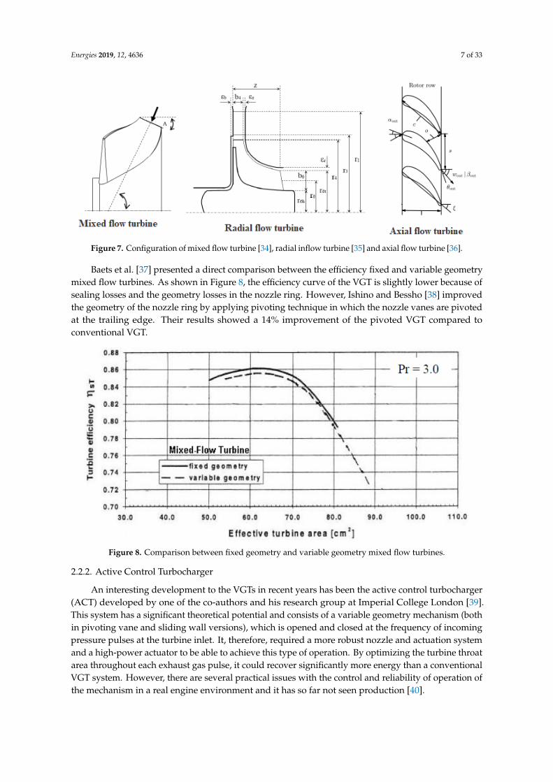
The configuration of the turbine can be axial, radial, or mixed flow. Axial and radial turbines are
commonly applied in turbocharging. However, small axial flow turbines suffer from the high tip
leakage at the rotor blade. Similarly, radial turbines have a limited operating range because of its inlet
geometrical requirements. Mixed flow turbines (which is a modified radial turbine configuration as
can be seen in Figure 7) have an advantage of the cone angle, which is between axial and radial. As a
result, the design of mixed flow turbines has more freedom and, consequently, a wider range of
operation. This enables the mixed flow turbines to accomplish higher mass‐induced mass flow rate
and optimum efficiency at lower velocity ratios, compared to equivalent radial ones.
Figure 6. Turbine with different stator positions (variable geometry turbine (VGT)), (a) closed, (b) mid,(c) open [33].
The configuration of the turbine can be axial, radial, or mixed flow. Axial and radial turbinesare commonly applied in turbocharging. However, small axial flow turbines suffer from the high tipleakage at the rotor blade. Similarly, radial turbines have a limited operating range because of itsinlet geometrical requirements. Mixed flow turbines (which is a modified radial turbine configurationas can be seen in Figure 7) have an advantage of the cone angle, which is between axial and radial.As a result, the design of mixed flow turbines has more freedom and, consequently, a wider range ofoperation. This enables the mixed flow turbines to accomplish higher mass-induced mass flow rateand optimum efficiency at lower velocity ratios, compared to equivalent radial ones.
Energies 2019, 12, 4636 7 of 33
In VGT, Figure 6, the exhaust gas delivered by the engine is controlled and automatically
supplied to the turbine in order to permit turbine power to sufficiently provide energy, which drives
the compressor at the required boost level wherever the engine is running in its range. This can be
accomplished by varying the throat area of the turbine stator in order to control the mass flow of the
exhaust gas. As the throat area decreases, the exhaust pressure and the rotational speed increase.
Contrarily, increasing the throat area reduces the exhaust pressure and, consequently, the
turbocharger boost decreases.
Figure 6. Turbine with different stator positions (variable geometry turbine (VGT)), (a) closed, (b)
mid, (c) open [33].
The configuration of the turbine can be axial, radial, or mixed flow. Axial and radial turbines are
commonly applied in turbocharging. However, small axial flow turbines suffer from the high tip
leakage at the rotor blade. Similarly, radial turbines have a limited operating range because of its inlet
geometrical requirements. Mixed flow turbines (which is a modified radial turbine configuration as
can be seen in Figure 7) have an advantage of the cone angle, which is between axial and radial. As a
result, the design of mixed flow turbines has more freedom and, consequently, a wider range of
operation. This enables the mixed flow turbines to accomplish higher mass‐induced mass flow rate
and optimum efficiency at lower velocity ratios, compared to equivalent radial ones.
Figure 7. Configuration of mixed flow turbine [34], radial inflow turbine [35] and axial flow turbine [36].
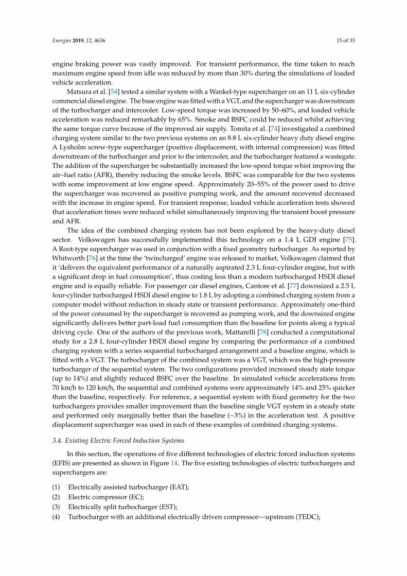
Baets et al. [37] presented a direct comparison between the efficiency fixed and variable geometrymixed flow turbines. As shown in Figure 8, the efficiency curve of the VGT is slightly lower because ofsealing losses and the geometry losses in the nozzle ring. However, Ishino and Bessho [38] improvedthe geometry of the nozzle ring by applying pivoting technique in which the nozzle vanes are pivotedat the trailing edge. Their results showed a 14% improvement of the pivoted VGT compared toconventional VGT.
Figure 7. Configuration of mixed flow turbine [34], radial inflow turbine [35] and axial flow turbine
[36].
Baets et al. [37] presented a direct comparison between the efficiency fixed and variable
geometry mixed flow turbines. As shown in Figure 8, the efficiency curve of the VGT is slightly lower
because of sealing losses and the geometry losses in the nozzle ring. However, Ishino and Bessho [38]
improved the geometry of the nozzle ring by applying pivoting technique in which the nozzle vanes
are pivoted at the trailing edge. Their results showed a 14% improvement of the pivoted VGT
compared to conventional VGT.
Figure 8. Comparison between fixed geometry and variable geometry mixed flow turbines.
2.2.2. Active Control Turbocharger
An interesting development to the VGTs in recent years has been the active control turbocharger
(ACT) developed by one of the co‐authors and his research group at Imperial College London [39].
This system has a significant theoretical potential and consists of a variable geometry mechanism
(both in pivoting vane and sliding wall versions), which is opened and closed at the frequency of
incoming pressure pulses at the turbine inlet. It, therefore, required a more robust nozzle and
actuation system and a high‐power actuator to be able to achieve this type of operation. By optimizing
the turbine throat area throughout each exhaust gas pulse, it could recover significantly more energy
than a conventional VGT system. However, there are several practical issues with the control and
reliability of operation of the mechanism in a real engine environment and it has so far not seen
production [40].
2.2.3. Twin and Double Turbine Scrolls
Figure 9 illustrates the difference between the twin entry and double entry configurations in
turbines. Two turbocharger turbine entries are used to ultimately increase the energy of the exhaust
driving the turbine in which the turbine wheel is directly fed with the highly pulsating flow twin or
double turbine scrolls. The double entry scroll delivers better efficiency at full load while the twin
entry scroll presents better performance at partial load.
Figure 8. Comparison between fixed geometry and variable geometry mixed flow turbines.
2.2.2. Active Control Turbocharger
An interesting development to the VGTs in recent years has been the active control turbocharger(ACT) developed by one of the co-authors and his research group at Imperial College London [39].This system has a significant theoretical potential and consists of a variable geometry mechanism (bothin pivoting vane and sliding wall versions), which is opened and closed at the frequency of incomingpressure pulses at the turbine inlet. It, therefore, required a more robust nozzle and actuation systemand a high-power actuator to be able to achieve this type of operation. By optimizing the turbine throatarea throughout each exhaust gas pulse, it could recover significantly more energy than a conventionalVGT system. However, there are several practical issues with the control and reliability of operation ofthe mechanism in a real engine environment and it has so far not seen production [40].
Energies 2019, 12, 4636 8 of 33
2.2.3. Twin and Double Turbine Scrolls
Figure 9 illustrates the difference between the twin entry and double entry configurations inturbines. Two turbocharger turbine entries are used to ultimately increase the energy of the exhaustdriving the turbine in which the turbine wheel is directly fed with the highly pulsating flow twin ordouble turbine scrolls. The double entry scroll delivers better efficiency at full load while the twinentry scroll presents better performance at partial load.
According to Watson and Janota [42], ‘supercharging can be defined as the introduction of air (orair/fuel mixture) into an engine cylinder at a density greater than the ambience’. This process allows aproportionally huge amount of fuel to be burned, thus increasing the potential power output of theengine. Three basic methods, namely, turbocharging, pressure wave supercharging, and mechanicalsupercharging, are used to achieve this condition.
3.1. Turbocharging
A turbocharger is a device with a compressor and turbine on a single shaft, and the turbine ispowered by energy in the engine’s exhaust gases to drive the compressor and increase the intakepressure. The design of such turbomachines is widely available in literature such as [43–46].
A Sankey diagram for a typical 1.4 L four-cylinder spark ignition (gasoline) engine is shown inFigure 10. A maximum of one-third of fuel energy is converted into useful work, and an average of15% of fuel energy is wasted as exhaust heat. One major benefit of a turbocharger is that it utilizesexhaust gas energy that would otherwise be wasted, thus leading to an overall improvement inthermal efficiency.
Energies 2019, 12, 4636 9 of 33
Figure 10. Sankey diagram showing energy balance for naturally aspirated spark ignition engine
[47].
In other works (particularly in Watson and Janota [42] and Baines [48]), conventional automotive
turbochargers use a centrifugal compressor and radial flow turbine. Such turbomachines have an
optimum operating point and ‘are unsuitable for operation under various flow ranges’ [42] because
of their design and operating principles. This case is applicable for an automotive engine. Emission
reduction technologies, such as exhaust gas recirculation and diesel particulate filters, render
compressor and turbine matching as problematic [49 Several authors [17,42,48,50,51] indicated a fundamental agreement when matching a turbocharger and an engine, that is, torque at low speed
and power at high engine speed. A large turbocharger provides power at high speed but experiences
low‐speed performance and transient response because of the lack of exhaust gas flow rate to
overcome the inertia of the system. A small turbocharger provides improved low‐speed torque and
transient response because of the reduced inertia, although it requires turbine bypassing to prevent
excessive turbocharger speed at high engine speeds, thus sacrificing the efficiency. Small
turbochargers generally exhibit low efficiency because of the increased leakage pressure losses
between the turbine and housing. This low‐speed performance impairment is compounded with
highly boosted engines [17,52]. The drivability characteristics of a comparable naturally aspirated
unit are the aim of a forced reduction engine, and various solutions have been introduced to diminish
the effects of this turbocharging compromise.
A turbine bypass—or ‘wastegate’—actualizes the correct sizing for a turbocharger under low
engine speed [48]. The wastegate is opened with an increase in speed, thus allowing a proportion of
exhaust gas to bypass the turbine, limiting the boost pressure and preventing the overspeeding of the
turbocharger. However, thermal efficiency is relinquished because the bypassed exhaust gas energy
is wasted.
Variable geometry turbine indicates that the effective turbine area (or aspect ratio) can be
matched to the changing exhaust gas flow rate [53]. The concepts designed to achieve this condition
can be classified into two categories depending on the adjustability of the geometry of the volute or
nozzle. According to Matsura et al. [54], a turbocharger with variable geometry volute is a low‐cost
alternative to variable geometry nozzle arrangements, which are generally complex. Despite
experimentally demonstrated improvements in transient response [54–56], only a few variable
geometry volute designs have attained commercial production. Baines [48] indicated that this
condition may be because of the aerodynamic inefficiency issues relative to fixed geometry
counterparts and the durability and performance deterioration in service. Turbochargers with
variable nozzle geometry have achieved huge commercial success. Variable nozzle devices have two
principal types, namely, pivoting vanes and moving sidewall [48], and can provide (amongst other
Figure 10. Sankey diagram showing energy balance for naturally aspirated spark ignition engine [47].
In other works (particularly in Watson and Janota [42] and Baines [48]), conventional automotiveturbochargers use a centrifugal compressor and radial flow turbine. Such turbomachines havean optimum operating point and ‘are unsuitable for operation under various flow ranges’ [42]because of their design and operating principles. This case is applicable for an automotive engine.Emission reduction technologies, such as exhaust gas recirculation and diesel particulate filters,render compressor and turbine matching as problematic [49] Several authors [17,42,48,50,51] indicateda fundamental agreement when matching a turbocharger and an engine, that is, torque at lowspeed and power at high engine speed. A large turbocharger provides power at high speed butexperiences low-speed performance and transient response because of the lack of exhaust gas flowrate to overcome the inertia of the system. A small turbocharger provides improved low-speedtorque and transient response because of the reduced inertia, although it requires turbine bypassingto prevent excessive turbocharger speed at high engine speeds, thus sacrificing the efficiency. Smallturbochargers generally exhibit low efficiency because of the increased leakage pressure losses betweenthe turbine and housing. This low-speed performance impairment is compounded with highly boostedengines [17,52]. The drivability characteristics of a comparable naturally aspirated unit are the aim of aforced reduction engine, and various solutions have been introduced to diminish the effects of thisturbocharging compromise.
A turbine bypass—or ‘wastegate’—actualizes the correct sizing for a turbocharger under lowengine speed [48]. The wastegate is opened with an increase in speed, thus allowing a proportion ofexhaust gas to bypass the turbine, limiting the boost pressure and preventing the overspeeding of theturbocharger. However, thermal efficiency is relinquished because the bypassed exhaust gas energyis wasted.
Variable geometry turbine indicates that the effective turbine area (or aspect ratio) can be matchedto the changing exhaust gas flow rate [53]. The concepts designed to achieve this condition can beclassified into two categories depending on the adjustability of the geometry of the volute or nozzle.According to Matsura et al. [54], a turbocharger with variable geometry volute is a low-cost alternativeto variable geometry nozzle arrangements, which are generally complex. Despite experimentallydemonstrated improvements in transient response [54–56], only a few variable geometry volute designshave attained commercial production. Baines [48] indicated that this condition may be because ofthe aerodynamic inefficiency issues relative to fixed geometry counterparts and the durability andperformance deterioration in service. Turbochargers with variable nozzle geometry have achieved hugecommercial success. Variable nozzle devices have two principal types, namely, pivoting vanes andmoving sidewall [48], and can provide (amongst other benefits) improved transient performance [54]and low speed boost [57]. By using a variable nozzle turbocharger fitted to 1.8 L direct injection dieselengine, Hawley et al. [58] increased the torque in the entire engine speed range compared with an
Energies 2019, 12, 4636 10 of 33
equivalent fixed geometry unit. Wijetunge et al. [17] and Matsura et al. [54] believed that variablegeometry turbochargers rely on the build-up of exhaust gas energy and thus do not completely solvethe problem of transient response, particularly at low engine speeds. Variable nozzle devices withhuge proliferation (as opposed to variable geometry volute) shall be referred to as ‘variable geometryturbocharger’ (VGT).
Various arrangements are used in multiple turbochargers and generally classified into threecategories, namely; series, parallel, and sequential. Several factors limiting the pressure ratio, such asefficiency reductions at high-pressure ratios, mass flow range requirements, and temperature limits [48],can be overcome by a single compressor. A series turbocharged configuration may become viablewith the increasing boost pressure (i.e., pressure ratio) requirements, which is the case in downsizing.Considering a two-stage system, two turbochargers are placed in series such that the exhaust gasesundergo two expansion stages and the intake charge goes through two compression stages. Watsonand Janota [42] indicated that ‘high overall pressure and expansion ratios may be developed by usingconventional turbochargers’ without relinquishing efficiency or mass flow range. Series systemsmay include bypass valves (for turbines and/or compressors) for immense operation flexibility asshown in Figure 11 (reproduced from Pflüger [59]). A two-stage arrangement by Pfluger [59] on a12 L commercial diesel engine showed increased torque at all engine speeds, increased rated power,improved air supply, reduced BSFC and smoke, and potential to reduce NOx emissions compared withan equivalent single-stage system. Although transient tests are not performed, the transient responsecould potentially be improved with a two-stage system. Baines [48] and Watson and Janota [42]highlighted the disadvantages of series turbocharging, such as the costs of extra turbocharger andintercooler (which is usually required), increased bulk and complexity of the system, and additionalpressure losses. Baines [48] stated that the transient performance of a two-stage system is generallyworse than that of an equivalent single-stage unit because the exhaust gas energy available to acceleratethe two turbochargers is shared between them. In a computational investigation by Saulnier andGuilain [60], a 2.0 L diesel engine was downsized to 1.5 L by moving from single-stage to two-stageturbocharging; equivalent steady-state performance was easily achieved, but the low-speed transientresponse worsened.
Energies 2019, 12, 4636 11 of 33
Figure 11. Schematic diagram of regulated series (two‐stage) turbocharging system [59].
In a parallel turbocharged arrangement, two (or four) turbochargers of equal size are used to
replace a large single unit. Parallel turbocharging is typically used on engines with six or more
cylinders by dividing the exhaust pipes from the cylinders into groups, which are favourable for
exhaust pulse effects (pulse turbocharging is comprehensively studied by Watson and Janota [42]).
In a system with two turbochargers, each turbine receives exhaust gases from half of the cylinders of
the engine, and the compressors generally feed into a common intake plenum on the intake side as
shown in Figure 12. For the aforementioned exhaust pulse effects, the benefits of parallel
turbocharging are reduced (combined) turbocharger inertia for improved transient response [61,62]
and simplified packaging, particularly for V‐type engines [42,61]. As discovered by Sommerhoff [61],
the net gain of a parallel system is controversial compared with that of a single turbocharger setup
because of some factors, such as the high efficiency of large turbomachinery and an associated
reduction in back pressure.
Figure 11. Schematic diagram of regulated series (two-stage) turbocharging system [59].
In a parallel turbocharged arrangement, two (or four) turbochargers of equal size are used toreplace a large single unit. Parallel turbocharging is typically used on engines with six or morecylinders by dividing the exhaust pipes from the cylinders into groups, which are favourable forexhaust pulse effects (pulse turbocharging is comprehensively studied by Watson and Janota [42]). Ina system with two turbochargers, each turbine receives exhaust gases from half of the cylinders ofthe engine, and the compressors generally feed into a common intake plenum on the intake side asshown in Figure 12. For the aforementioned exhaust pulse effects, the benefits of parallel turbochargingare reduced (combined) turbocharger inertia for improved transient response [61,62] and simplifiedpackaging, particularly for V-type engines [42,61]. As discovered by Sommerhoff [61], the net gainof a parallel system is controversial compared with that of a single turbocharger setup because ofsome factors, such as the high efficiency of large turbomachinery and an associated reduction inback pressure.
Energies 2019, 12, 4636 12 of 33
Figure 12. Schematic diagram of a parallel twin turbocharging system.
In a sequential system, Figure 13, two (or more) turbochargers are arranged in parallel and
supply charge air to a common intake manifold, similar to parallel turbocharging. Different from a
purely parallel configuration, the turbines are driven by exhaust gases from a common exhaust
manifold, and the number of turbochargers in operation varies depending on the systematic use of
flow control valves. The turbochargers used may be of equal (or similar) size. For a twin‐turbo
system, only one turbocharger is in operation during the first sequence (at low engine speeds), and
two turbochargers are used during the second sequence (high engine speeds). Tashima et al. [63]
developed this system for a 1.3 L gasoline rotary (Wankel) engine. Alternatively, a small turbocharger
may be used for low engine speed operation, switching solely to a large turbocharger at high engine
speeds. Hancock et al. [15] used this system but serially arranged the turbochargers on a highly
downsized 1.2 L three‐cylinder GDI engine. These two cases have a similar purpose and result:
Changing the effective turbine area to match the engine speed and exhaust gas flow and improve the
low‐speed boost, torque, and transient response. Baines [48] described the effect to ‘a stepwise
variable geometry scheme’. In the aforementioned work of Tashima et al. [63], boost pressure and
torque were substantially improved (by 200% and 36%, respectively) at low engine speeds compared
with those of a conventional turbocharger. In vehicle acceleration tests, transient response was
markedly superior as indicated by the 43% reduction in the time taken to reach maximum boost.
Similar improvements were exhibited in computational simulations of a 2.5 L four‐cylinder gasoline
engine conducted by Brüstle et al. [64]. For the disadvantages of sequential turbocharging, Tashima
et al. [63] and Baines [48] indicated the need for systematic matching of the turbochargers and engine
speed with sequence transition, which is crucial in avoiding a drop in torque prior to the switch and
compressor surge (and choking). For other multiturbocharger schemes, additional plumbing and
associated potential pressure losses must be considered. In relation to VGTs, Wijetunge et al. [17]
asserted that the transient response of any of these turbocharged systems is ultimately limited by the
available exhaust gas energy, and any transient response issues are multiplied in highly boosted (e.g.,
highly downsized) applications.
Figure 12. Schematic diagram of a parallel twin turbocharging system.
In a sequential system, Figure 13, two (or more) turbochargers are arranged in parallel andsupply charge air to a common intake manifold, similar to parallel turbocharging. Different froma purely parallel configuration, the turbines are driven by exhaust gases from a common exhaustmanifold, and the number of turbochargers in operation varies depending on the systematic useof flow control valves. The turbochargers used may be of equal (or similar) size. For a twin-turbosystem, only one turbocharger is in operation during the first sequence (at low engine speeds), andtwo turbochargers are used during the second sequence (high engine speeds). Tashima et al. [63]developed this system for a 1.3 L gasoline rotary (Wankel) engine. Alternatively, a small turbochargermay be used for low engine speed operation, switching solely to a large turbocharger at high enginespeeds. Hancock et al. [15] used this system but serially arranged the turbochargers on a highlydownsized 1.2 L three-cylinder GDI engine. These two cases have a similar purpose and result:Changing the effective turbine area to match the engine speed and exhaust gas flow and improve thelow-speed boost, torque, and transient response. Baines [48] described the effect to ‘a stepwise variablegeometry scheme’. In the aforementioned work of Tashima et al. [63], boost pressure and torque weresubstantially improved (by 200% and 36%, respectively) at low engine speeds compared with those ofa conventional turbocharger. In vehicle acceleration tests, transient response was markedly superior asindicated by the 43% reduction in the time taken to reach maximum boost. Similar improvements wereexhibited in computational simulations of a 2.5 L four-cylinder gasoline engine conducted by Brüstle etal. [64]. For the disadvantages of sequential turbocharging, Tashima et al. [63] and Baines [48] indicatedthe need for systematic matching of the turbochargers and engine speed with sequence transition,which is crucial in avoiding a drop in torque prior to the switch and compressor surge (and choking).For other multiturbocharger schemes, additional plumbing and associated potential pressure lossesmust be considered. In relation to VGTs, Wijetunge et al. [17] asserted that the transient response ofany of these turbocharged systems is ultimately limited by the available exhaust gas energy, and anytransient response issues are multiplied in highly boosted (e.g., highly downsized) applications.
Energies 2019, 12, 4636 13 of 33
Figure 13. Schematic diagram of a sequential twin turbocharging system [65].
3.2. Mechanical Supercharging
Mechanical supercharging occurs when the increased charge air density is provided by a pump
or compressor, which is usually driven from the engine crankshaft via a gear train or belt and pulley
system. The term ‘supercharger’ is usually reserved for mechanically driven systems [66], and this
precedent will be maintained from here onwards. Superchargers can be categorised based on the
compression methods, such as positive displacement and dynamic compressor.
A positive displacement pump displaces fluid in a pipe system by cyclically trapping and
discharging a fixed amount of fluid. In an automotive context, increased charge density is
accomplished by pumping the air into the intake at a faster rate than the engine would normally
ingest. Considering that the rate is fixed relative to engine speed (with fixed drive ratio), positive
displacement superchargers are capable of producing a constant boost pressure. The mechanical
drive results in good transient response, but the downside is that power is drawn from the useful
output of the engine rather than utilising the ‘free’ exhaust gas energy similar to that in
turbocharging. Some of the energy used by the supercharger are recovered as positive pumping work
on the pistons [66]; by contrast, a turbocharger raises exhaust backpressure and thus increases
pumping losses and trapped residuals [67]. Bhinder [66] indicated that a major disadvantage of
positive displacement superchargers is that their size and weight are relative to the boost provided.
Many different designs of positive displacement superchargers, including roots, screw (such as
Lysholm compressor), sliding vane, and scroll, have been developed and received varying degrees
of commercial success. Root‐type superchargers do not provide internal compression compared with
other types listed here and thus have a relatively low efficiency (Stone [68] for details). Recent
developments, such as in Eaton’s twin vortices series (TVS) [69], with reduced clearances and
improved flow characteristics, have brought a huge improvement. Devices with internal
compression, such as Lysholm compressor, provide large volumetric and isentropic efficiencies [70]
but require a high cost for manufacturing precision requirements [66]. The analysis of Stone [68]
revealed that these efficiency improvements are rapidly eroded when the internal compression ratio
of the device does not match the overall required pressure ratio, that is, during external compression
(or expansion). A Root‐type supercharger was used by Joyce [71] on a 4.0 L six‐cylinder gasoline
engine to increase torque and power by 35%–50% and exceeded the output of a naturally aspirated
6.0 L V12. At part load (equal torque), the supercharged engine has greater BSFC than the naturally
aspirated unit because of parasitic losses and reduced compression ratio. However, BSFC is
substantially lower for the supercharged engine than the large‐capacity V12 under the same
conditions due to the increased number of valves (cylinders) and hence higher fuel consumption.
Transient performance was not tested against naturally aspirated engines but was expected to
slightly diminish. Joyce [71] explained that ‘there is a finite time taken to compress the air in the
Figure 13. Schematic diagram of a sequential twin turbocharging system [65].
3.2. Mechanical Supercharging
Mechanical supercharging occurs when the increased charge air density is provided by a pumpor compressor, which is usually driven from the engine crankshaft via a gear train or belt and pulleysystem. The term ‘supercharger’ is usually reserved for mechanically driven systems [66], and thisprecedent will be maintained from here onwards. Superchargers can be categorised based on thecompression methods, such as positive displacement and dynamic compressor.
A positive displacement pump displaces fluid in a pipe system by cyclically trapping anddischarging a fixed amount of fluid. In an automotive context, increased charge density is accomplishedby pumping the air into the intake at a faster rate than the engine would normally ingest. Consideringthat the rate is fixed relative to engine speed (with fixed drive ratio), positive displacement superchargersare capable of producing a constant boost pressure. The mechanical drive results in good transientresponse, but the downside is that power is drawn from the useful output of the engine rather thanutilising the ‘free’ exhaust gas energy similar to that in turbocharging. Some of the energy used by thesupercharger are recovered as positive pumping work on the pistons [66]; by contrast, a turbochargerraises exhaust backpressure and thus increases pumping losses and trapped residuals [67]. Bhinder [66]indicated that a major disadvantage of positive displacement superchargers is that their size and weightare relative to the boost provided. Many different designs of positive displacement superchargers,including roots, screw (such as Lysholm compressor), sliding vane, and scroll, have been developedand received varying degrees of commercial success. Root-type superchargers do not provide internalcompression compared with other types listed here and thus have a relatively low efficiency (Stone [68]for details). Recent developments, such as in Eaton’s twin vortices series (TVS) [69], with reducedclearances and improved flow characteristics, have brought a huge improvement. Devices with internalcompression, such as Lysholm compressor, provide large volumetric and isentropic efficiencies [70] butrequire a high cost for manufacturing precision requirements [66]. The analysis of Stone [68] revealedthat these efficiency improvements are rapidly eroded when the internal compression ratio of thedevice does not match the overall required pressure ratio, that is, during external compression (orexpansion). A Root-type supercharger was used by Joyce [71] on a 4.0 L six-cylinder gasoline engineto increase torque and power by 35–50% and exceeded the output of a naturally aspirated 6.0 L V12.At part load (equal torque), the supercharged engine has greater BSFC than the naturally aspirated unitbecause of parasitic losses and reduced compression ratio. However, BSFC is substantially lower forthe supercharged engine than the large-capacity V12 under the same conditions due to the increasednumber of valves (cylinders) and hence higher fuel consumption. Transient performance was nottested against naturally aspirated engines but was expected to slightly diminish. Joyce [71] explainedthat ‘there is a finite time taken to compress the air in the volume between the blower and the engine.Thus, the mass of air delivered by the supercharger is different from that received by the engine’
Energies 2019, 12, 4636 14 of 33
under changing speed. Engine performance is reduced in reference to the steady state maximum.This condition formed the basis of using a variable supercharger drive ratio, such as in a CVT. Stone [72]addressed the point of a continuously variable drive ratio but in relation to reducing the part-loadthrottling losses. Considering the performance differences between supercharging and turbocharging,Richter and Hemmerlein [73] performed a comparative study on a 2.5 L four-cylinder gasoline engine.The supercharged version showed a torque advantage of 50–70% at low to medium engine speeds,and torque was approximately identical at high engine speeds. However, turbochargers allow smallerengine displacements to produce much more power relative to their size and improve fuel economy.Joyce [71] and Richter and Hemmerlein [73] applied a bypass valve around the respective superchargersfor part-load operation.
Dynamic compressors include centrifugal (radial flow) and axial compressors, and the centrifugaltype is more common of the two for automotive supercharger use. A centrifugal compressor worksby accelerating the intake air to a high velocity, and this velocity is converted to pressure by meansof diffusion [42]. Consequently, the produced pressure ratio increases with the compressor speed.Thus, the mechanically driven centrifugal supercharger boost increases with engine speed at a fixedratio as reported by Bhinder [66], making it incompatible for automotive engines. This characteristicof centrifugal compressors is not a problem when it is used in a turbocharger because the latter’sspeed independently varies from engine’s speed. Centrifugal superchargers are typically small,light, and capable of producing higher pressure ratios than their positive displacement counterparts.Although the increasing boost with engine speed attribute is a drawback, it also allows the use of a highcompression ratio in gasoline engines. In this case, air flow can be improved at high engine speeds wherevolumetric efficiency would usually drop without significantly increasing cylinder pressures at low tomedium engine speeds, thus avoiding auto ignition (knock). This benefit is relevant to applicationswhere performance at high engine speeds is importance, especially on specialist high-performancecar manufacturers Koenigsegg and Caterham [58]. Following on from his earlier line of reasoning,Bhinder [66] suggested that driving a centrifugal supercharger through a variable transmission wouldmatch the boost to to the engine requirements at any given speed and load. This idea is being developedby Rotrak [67], a joint venture between centrifugal supercharger manufacturer Rotrex and variabletransmission specialist Torotrak. The Rotrak device combines a full-toroidal variator with a centrifugalsupercharger, where the latter incorporates a compact, innovative epicyclical traction drive patented byRotrex and has a single-stage step up ratio of approximately 13:1 to achieve the high speeds requiredby the compressor. No results for performance simulations or engine testing have been published, butthe technologies are mature and have been proven individually. Listing the potential benefits of theRotrak concept for gasoline engines, Stone [67] stated that the engine load via the boost pressure canbe controlled (i.e., by controlling compressor speed), thereby reducing the throttling of the engine andthe pumping losses.
3.3. Combined Charging Systems
At low engine speeds, a pressure charging system would incorporate the transient response andtorque, which can be provided by a mechanical supercharger with high efficiency and the part-loadflexibility of a turbocharger. One solution to this dilemma is to simply combine a declutchablesupercharger with a conventional turbocharger in a sequential series arrangement, and such systemshave been investigated, particularly for heavy duty diesel applications [52,54,74]. This configurationshall hereafter be referred to as a ‘combined charging system’. Schmitz et al. [52] investigated acombined charging system for a 10.9 L V6 commercial diesel engine with a positive displacementsupercharger (Wankel-type, which has internal compression) that is upstream of a fixed geometryturbocharger. An electromagnetic clutch was fitted to the supercharger drive pulley for the superchargerto disengage (in conjunction with an intake bypass valve) at high engine speeds or low loads andmaintain efficiency. Compared with the purely turbocharged engine, the combined charging systemprovided significantly increased low speed boost and torque with only a small BSFC penalty. Available
Energies 2019, 12, 4636 15 of 33
engine braking power was vastly improved. For transient performance, the time taken to reachmaximum engine speed from idle was reduced by more than 30% during the simulations of loadedvehicle acceleration.
Matsura et al. [54] tested a similar system with a Wankel-type supercharger on an 11 L six-cylindercommercial diesel engine. The base engine was fitted with a VGT, and the supercharger was downstreamof the turbocharger and intercooler. Low-speed torque was increased by 50–60%, and loaded vehicleacceleration was reduced remarkably by 65%. Smoke and BSFC could be reduced whilst achievingthe same torque curve because of the improved air supply. Tomita et al. [74] investigated a combinedcharging system similar to the two previous systems on an 8.8 L six-cylinder heavy duty diesel engine.A Lysholm screw-type supercharger (positive displacement, with internal compression) was fitteddownstream of the turbocharger and prior to the intercooler, and the turbocharger featured a wastegate.The addition of the supercharger be substantially increased the low-speed torque whist improving theair–fuel ratio (AFR), thereby reducing the smoke levels. BSFC was comparable for the two systemswith some improvement at low engine speed. Approximately 20–55% of the power used to drivethe supercharger was recovered as positive pumping work, and the amount recovered decreasedwith the increase in engine speed. For transient response, loaded vehicle acceleration tests showedthat acceleration times were reduced whilst simultaneously improving the transient boost pressureand AFR.
The idea of the combined charging system has not been explored by the heavy-duty dieselsector. Volkswagen has successfully implemented this technology on a 1.4 L GDI engine [75].A Root-type supercharger was used in conjunction with a fixed geometry turbocharger. As reported byWhitworth [76] at the time the ‘twincharged’ engine was released to market, Volkswagen claimed thatit ‘delivers the equivalent performance of a naturally aspirated 2.3 L four-cylinder engine, but witha significant drop in fuel consumption’, thus costing less than a modern turbocharged HSDI dieselengine and is equally reliable. For passenger car diesel engines, Cantore et al. [77] downsized a 2.5 Lfour-cylinder turbocharged HSDI diesel engine to 1.8 L by adopting a combined charging system from acomputer model without reduction in steady state or transient performance. Approximately one-thirdof the power consumed by the supercharger is recovered as pumping work, and the downsized enginesignificantly delivers better part-load fuel consumption than the baseline for points along a typicaldriving cycle. One of the authors of the previous work, Mattarelli [78] conducted a computationalstudy for a 2.8 L four-cylinder HSDI diesel engine by comparing the performance of a combinedcharging system with a series sequential turbocharged arrangement and a baseline engine, which isfitted with a VGT. The turbocharger of the combined system was a VGT, which was the high-pressureturbocharger of the sequential system. The two configurations provided increased steady state torque(up to 14%) and slightly reduced BSFC over the baseline. In simulated vehicle accelerations from70 km/h to 120 km/h, the sequential and combined systems were approximately 14% and 25% quickerthan the baseline, respectively. For reference, a sequential system with fixed geometry for the twoturbochargers provides smaller improvement than the baseline single VGT system in a steady stateand performed only marginally better than the baseline (~3%) in the acceleration test. A positivedisplacement supercharger was used in each of these examples of combined charging systems.
3.4. Existing Electric Forced Induction Systems
In this section, the operations of five different technologies of electric forced induction systems(EFIS) are presented as shown in Figure 14. The five existing technologies of electric turbochargers andsuperchargers are:
(1) Electrically assisted turbocharger (EAT);(2) Electric compressor (EC);(3) Electrically split turbocharger (EST);(4) Turbocharger with an additional electrically driven compressor—upstream (TEDC);
Energies 2019, 12, 4636 16 of 33
(5) Turbocharger with an additional electrically driven compressor—downstream (TEDC) fluids.
(5) Turbocharger with an additional electrically driven compressor—downstream (TEDC) fluids.
3.4.1. Electrically assisted turbocharger
The electrically assisted turbocharger (EAT, also referred as hybrid turbocharger) topology is
shown in Figure 14a. Between the compressor and the turbine, a high‐speed electric machine is fitted
[79], see Figure 15. At low engine speed, additional torque is provided to the compressor, as the
electric machine operates as a motor; thus the boost pressure is increased, which results in the
reduction of the transient response [80]. On the other hand, at high engine speed, power is generated
and transmitted to the energy storage as the electric machine functions as a generator.
Ricardo et al. [79] stated that investigation on the electrically assisted turbochargers is needed as
they are beneficial to eliminate the turbo‐lag. Moreover, another advantage of the hybrid
turbochargers is that the turbocharger speed is maintained during gearshifts. In addition to that, at
high engine speeds, the turbocharger speed is reduced [79].
Figure 14. Cont.
Energies 2019, 12, 4636 17 of 33
Figure 14. Schematic layout of electric forced induction system (EFIS) topologies (black line (thin)—
power flow, black line (thick)—air flow path with valve, blue line—engine inlet air flow, red line—
exhaust gas flow). (a) Electrically assisted turbocharger (EAT). (b) Electric compressor (EC). (c)
Electrically split turbocharger (EST). (d) Turbocharger with an additional electrically driven
compressor—upstream (TEDC). (e) Turbocharger with an additional electrically driven compressor—
downstream (TEDC).
Figure 14. Schematic layout of electric forced induction system (EFIS) topologies (black line(thin)—power flow, black line (thick)—air flow path with valve, blue line—engine inlet air flow,red line—exhaust gas flow). (a) Electrically assisted turbocharger (EAT). (b) Electric compressor(EC). (c) Electrically split turbocharger (EST). (d) Turbocharger with an additional electricallydriven compressor—upstream (TEDC). (e) Turbocharger with an additional electrically drivencompressor—downstream (TEDC).
3.4.1. Electrically assisted turbocharger
The electrically assisted turbocharger (EAT, also referred as hybrid turbocharger) topology isshown in Figure 14a. Between the compressor and the turbine, a high-speed electric machine isfitted [79], see Figure 15. At low engine speed, additional torque is provided to the compressor, asthe electric machine operates as a motor; thus the boost pressure is increased, which results in thereduction of the transient response [80]. On the other hand, at high engine speed, power is generatedand transmitted to the energy storage as the electric machine functions as a generator.
Energies 2019, 12, 4636 18 of 33
Figure 15. Integration of electric machine with turbocharger.
Similarly, a recent paper by Lee et al. [81] supported that electrically assisted turbochargers
provide higher boosting at low RPM than a conventional turbocharger and the power output, which
is consumed by the motor and inverter is low. On the other hand, the shaft inertia is increased since
the electric machine is interconnected between the turbine and the compressor [81], thus for the
turbocharger operation, more power is required. Furthermore, another drawback of this topology is
the high‐temperature effect on the electric machine, hence, an additional cooling is needed. To
mitigate the high‐temperature effect, Lee et al. [81] presented some topological approaches. First, the
electric machine can be connected or disconnected to the shaft with the usage of clutches, so the
machine can be installed outside of the turbocharger. Second, a large airgap permanent magnet
machine could be used, which can be located outside of the turbocharger. This electric machine
decreases the temperature effect as the airgap is used as inlet air path.
3.4.2. Electric Supercharger
Electric supercharger is also referred as hybrid supercharger or electric compressor or e‐booster,
see Figure 16. The solely difference between electric supercharger and turbocharger is the omission
of the turbine [79] as is shown in Figure 14b. This is beneficial as not only is no additional inertia to
the system from the turbine and the turbine shaft, but also because the backpressure effect is
eliminated. Similarly, Villegas et al. [82] stated that the friction losses are decreased since there are no
mechanical connections between the engine and the e‐compressor. Furthermore, in this topology, the
boost pressure is increased at the transient response at low engine speeds.
Moreover, the compressor is electrically driven by an electric machine which makes the control
more flexible [81]. However, due to the incapability of this topology to generate energy itself,
electrical energy has to be provided to the storage by an integrated starter generator (ISG) or the
regenerative braking system [83]. In addition, according to Lee et al. [81], the main drawback of this
topology is the low system efficiency. Also, the development of the e‐ compressor has faced a
challenge since cars are being designed to work on 12V architecture [84]. However, some automobile
makers have been considered to use a 48V battery. According to a simulation that was conducted by
Nishiwaki et al. [85] for a 48V battery system, the regenerative electric power and the motor power
were risen as the boosting pressure was increased. This was due to the higher power produced by
Figure 15. Integration of electric machine with turbocharger.
Ricardo et al. [79] stated that investigation on the electrically assisted turbochargers is needed asthey are beneficial to eliminate the turbo-lag. Moreover, another advantage of the hybrid turbochargersis that the turbocharger speed is maintained during gearshifts. In addition to that, at high enginespeeds, the turbocharger speed is reduced [79].
Similarly, a recent paper by Lee et al. [81] supported that electrically assisted turbochargersprovide higher boosting at low RPM than a conventional turbocharger and the power output, which isconsumed by the motor and inverter is low. On the other hand, the shaft inertia is increased sincethe electric machine is interconnected between the turbine and the compressor [81], thus for theturbocharger operation, more power is required. Furthermore, another drawback of this topology isthe high-temperature effect on the electric machine, hence, an additional cooling is needed. To mitigatethe high-temperature effect, Lee et al. [81] presented some topological approaches. First, the electricmachine can be connected or disconnected to the shaft with the usage of clutches, so the machine can beinstalled outside of the turbocharger. Second, a large airgap permanent magnet machine could be used,which can be located outside of the turbocharger. This electric machine decreases the temperatureeffect as the airgap is used as inlet air path.
3.4.2. Electric Supercharger
Electric supercharger is also referred as hybrid supercharger or electric compressor or e-booster,see Figure 16. The solely difference between electric supercharger and turbocharger is the omission ofthe turbine [79] as is shown in Figure 14b. This is beneficial as not only is no additional inertia to thesystem from the turbine and the turbine shaft, but also because the backpressure effect is eliminated.Similarly, Villegas et al. [82] stated that the friction losses are decreased since there are no mechanicalconnections between the engine and the e-compressor. Furthermore, in this topology, the boost pressureis increased at the transient response at low engine speeds.
Energies 2019, 12, 4636 19 of 33
the 48V. Consequently, higher boost pressure and fast response time were resulted. Therefore, the
electric power that is required for the e‐booster operation can be covered by the regenerative energy.
Finally, the results of the simulation have shown a significant improvement in the transient response
at low engine speeds [85].
Figure 16. Electric supercharger.
3.4.3. Electrically Split Turbocharger
As shown in Figure 14c, in the electrically split turbocharger, the turbine and the compressor are
not connected to the same shaft. However, the mechanical energy from the exhaust gas is converted
to electrical and stored in the energy storage. This energy is used to drive the compressor for boosting
[81].
The main advantage of this system is that the compressor and the turbine can rotate
independently; hence, they can have different speeds. Moreover, since the compressor and turbine
are separated, the temperature effect is decreased compared to an electrically assisted turbocharger
[81]. On the other hand, Lee et al. [81] stated that due to the high power output consumption of the
motor, generator, and inverters, the system’s cost will be increased. Furthermore, there is an
additional energy conversion loss as two inverters are required, for the system operation.
3.4.4. Turbocharger with an Additional Electrically Driven Compressor—Upstream and
Downstream (TEDC)
In Figure 14d,e, the topology of a turbocharger with an additional electrically driven compressor
(TEDC), located upstream and downstream, respectively, is shown. In this turbocharger, the electric
machine is connected to the electrically driven compressor and is not affected by the exhaust gas
driven turbine. Thus, since the electric machine drives solely the compressor, the transient response
is improved for low engine speed as the boost pressure build‐up is made faster [83]. Moreover,
according to Lee et al. [81], the benefits of the topology are the low power consumption of the electric
motor and inverter as well as the improvement of the steady state performance. It is obvious that the
TEDC downstream has faster transient response compared to the upstream topology since the latter
has to compress a larger volume.
In a recent paper by Nishiwaki et al. [85], the topology in Figure 14e is referred to as a two‐stage
turbocharger system. In addition, in the paper, a TEDC system on a 1.5‐litre gasoline engine was
examined by GT‐Power, an engine simulation tool, and engine bench test. Results obtained by
Figure 16. Electric supercharger.
Moreover, the compressor is electrically driven by an electric machine which makes the controlmore flexible [81]. However, due to the incapability of this topology to generate energy itself, electricalenergy has to be provided to the storage by an integrated starter generator (ISG) or the regenerativebraking system [83]. In addition, according to Lee et al. [81], the main drawback of this topology isthe low system efficiency. Also, the development of the e- compressor has faced a challenge sincecars are being designed to work on 12V architecture [84]. However, some automobile makers havebeen considered to use a 48V battery. According to a simulation that was conducted by Nishiwakiet al. [85] for a 48V battery system, the regenerative electric power and the motor power were risenas the boosting pressure was increased. This was due to the higher power produced by the 48V.Consequently, higher boost pressure and fast response time were resulted. Therefore, the electricpower that is required for the e-booster operation can be covered by the regenerative energy. Finally,the results of the simulation have shown a significant improvement in the transient response at lowengine speeds [85].
3.4.3. Electrically Split Turbocharger
As shown in Figure 14c, in the electrically split turbocharger, the turbine and the compressor arenot connected to the same shaft. However, the mechanical energy from the exhaust gas is converted toelectrical and stored in the energy storage. This energy is used to drive the compressor for boosting [81].
The main advantage of this system is that the compressor and the turbine can rotate independently;hence, they can have different speeds. Moreover, since the compressor and turbine are separated, thetemperature effect is decreased compared to an electrically assisted turbocharger [81]. On the otherhand, Lee et al. [81] stated that due to the high power output consumption of the motor, generator, andinverters, the system’s cost will be increased. Furthermore, there is an additional energy conversionloss as two inverters are required, for the system operation.
3.4.4. Turbocharger with an Additional Electrically Driven Compressor—Upstream andDownstream (TEDC)
In Figure 14d,e, the topology of a turbocharger with an additional electrically driven compressor(TEDC), located upstream and downstream, respectively, is shown. In this turbocharger, the electricmachine is connected to the electrically driven compressor and is not affected by the exhaust gasdriven turbine. Thus, since the electric machine drives solely the compressor, the transient response isimproved for low engine speed as the boost pressure build-up is made faster [83]. Moreover, according
Energies 2019, 12, 4636 20 of 33
to Lee et al. [81], the benefits of the topology are the low power consumption of the electric motorand inverter as well as the improvement of the steady state performance. It is obvious that the TEDCdownstream has faster transient response compared to the upstream topology since the latter has tocompress a larger volume.
In a recent paper by Nishiwaki et al. [85], the topology in Figure 14e is referred to as a two-stageturbocharger system. In addition, in the paper, a TEDC system on a 1.5-litre gasoline engine wasexamined by GT-Power, an engine simulation tool, and engine bench test. Results obtained byNishiwaki et al. [85] suggest that the TEDC system’s response time at 1500 rpm was improved by 43%,compared with a normal two-stage turbocharger.
On the other hand, the main disadvantage of the TEDC is that the electric energy required todrive the compressor needs to be generated by generator/alternator powered by the engine shaft orregenerative braking system [83]. Furthermore, another major drawback that should be considered isthe low system efficiency of the topology [81].
3.4.5. Superturbocharging
The combination (electrical or mechanical) of superchargers and turbochargers in a system isreferred as Superturbocharging or “Superturbo”. Superturbocharging has two principal versions(electrical/mechanical) as follows:
(i) TurboSuperGenerator
TurboSuperGenerator (TSG), Figure 17, is a super-turbo system that not only benefits fromthe advantages of supercharging and turbocharging, but also benefits from the multi-stageturbocharging [79]. In the TSG, the engine alternator is replaced as boost is provided by superchargerand turbocharger. Moreover, the difference with the other super-turbo systems is that in TSG topologythe turbocharger is placed before the electric supercharger, hence the hybrid supercharger is the high-pressure compressor stage [84]. According to Baderman [84], integral Powertrain (IP) has developed aTSG, named SuperGen, which allow an aggressive downsizing without compromising on drivability.Furthermore, IP has proved that the acceleration time of TSG downsized engine was shorter than anormal-sized, naturally aspirated, or a sequentially turbocharged engine [84].
Nishiwaki et al. [85] suggest that the TEDC system’s response time at 1500 rpm was improved by
43%, compared with a normal two‐stage turbocharger.
On the other hand, the main disadvantage of the TEDC is that the electric energy required to
drive the compressor needs to be generated by generator/alternator powered by the engine shaft or
regenerative braking system [83]. Furthermore, another major drawback that should be considered
is the low system efficiency of the topology [81].
3.4.5. Superturbocharging
The combination (electrical or mechanical) of superchargers and turbochargers in a system is
referred as Superturbocharging or “Superturbo”. Superturbocharging has two principal versions
(electrical/mechanical) as follows:
(i) TurboSuperGenerator
TurboSuperGenerator (TSG), Figure 17, is a super‐turbo system that not only benefits from the
advantages of supercharging and turbocharging, but also benefits from the multi‐stage
turbocharging [79]. In the TSG, the engine alternator is replaced as boost is provided by supercharger
and turbocharger. Moreover, the difference with the other super‐turbo systems is that in TSG
topology the turbocharger is placed before the electric supercharger, hence the hybrid supercharger
is the high‐ pressure compressor stage [84]. According to Baderman [84], integral Powertrain (IP) has
developed a TSG, named SuperGen, which allow an aggressive downsizing without compromising
on drivability. Furthermore, IP has proved that the acceleration time of TSG downsized engine was
shorter than a normal‐sized, naturally aspirated, or a sequentially turbocharged engine [84].
Figure 17. Configuration of Turbosupergenerator (TSG) [79].
(ii) Mechanical Superturbocharger
It is an empowering topology for engine downsizing with no loss of vehicle transient response
and peak power. As shown in Figure 18, the main elements of the technology are a traction drive,
compressor, and turbine all being attached to a single crankshaft and subsequently connected to a
continuously variable transmission. This technology consists of two modes. The first one boosts
engine power via turbocompounding while the second transmits power from the engine to a
supercharger in order to boost the transient response at lower speeds.
Figure 17. Configuration of Turbosupergenerator (TSG) [79].
Energies 2019, 12, 4636 21 of 33
(ii) Mechanical Superturbocharger
It is an empowering topology for engine downsizing with no loss of vehicle transient responseand peak power. As shown in Figure 18, the main elements of the technology are a traction drive,compressor, and turbine all being attached to a single crankshaft and subsequently connected to acontinuously variable transmission. This technology consists of two modes. The first one boosts enginepower via turbocompounding while the second transmits power from the engine to a supercharger inorder to boost the transient response at lower speeds.
Figure 18. Configuration of Superturbocharger [86].
4. Turbocompounding
As discussed in Section 2.1, a turbocharger uses an exhaust‐driven turbine to power a
compressor and consequently increase the density of the air entering the engine. Harnessing the
power produced by the turbine in a different manner, such as by directly adding it to the useful
output of the engine, may be a beneficial approach. According to Watson and Janota [42], a
turbocompounded engine is one with ‘some mechanical linkage and power transmission between
the exhaust‐gas driven turbine and crankshaft of the engine’. However, this term also describes a
system in which the turbine drives an electrical generator, and the exhaust energy is recovered as
electrical power. Mechanical and electrical turbocompounding arrangements are explored in the
following section.
4.1. Mechanical Turbocompounding
Four basic mechanical turbocompounding arrangements with individual particular advantages
and disadvantages have been developed (Figure 19, reproduced from Baines [32]).
Figure 18. Configuration of Superturbocharger [86].
4. Turbocompounding
As discussed in Section 2.1, a turbocharger uses an exhaust-driven turbine to power a compressorand consequently increase the density of the air entering the engine. Harnessing the power producedby the turbine in a different manner, such as by directly adding it to the useful output of the engine,may be a beneficial approach. According to Watson and Janota [42], a turbocompounded engine is onewith ‘some mechanical linkage and power transmission between the exhaust-gas driven turbine andcrankshaft of the engine’. However, this term also describes a system in which the turbine drives anelectrical generator, and the exhaust energy is recovered as electrical power. Mechanical and electricalturbocompounding arrangements are explored in the following section.
4.1. Mechanical Turbocompounding
Four basic mechanical turbocompounding arrangements with individual particular advantagesand disadvantages have been developed (Figure 19, reproduced from Baines [32]).
turbocharger; (c) separate power turbine, series arrangement; (d) separate power turbine, parallel
arrangement [48].
In the first type, the engine shafts and turbocharger are directly linked (Figure 19a). However, a
fixed transmission ratio that corresponds to the engine and turbocharger speeds at all speed and load
conditions, with particular problems at part load, is difficult to choose for this arrangement similar
to the centrifugal supercharger [42,48]. Brockbank [87] discussed the use of CVT with this
arrangement, a modification that independently controls the turbocompounding level of the engine
speed. Furthermore, the turbocharger could intentionally be driven by the engine by manipulating
the CVT ratio when insufficient boost occurs. Hence, the turbocharger effectively acts as a
supercharger. A system of this type (with a CVT) was utilised on the well‐known Napier Nomad
aircraft engine of the 1950s [42,48]. According to Baines [48], such machine (and other contemporary
turbocompounded engines) shows potential but is notoriously complex and quickly superseded by
the advancing development of gas turbine engines. Chadwell and Walls [18] investigated the
VanDyne SuperTurbocharger, a modern counterpart for the automotive sector that offers
supercharging, turbocharging, and turbocompounding in one device. The SuperTurbocharger
consists of a turbocharger that transmits power to and from the engine crankshaft via a high‐speed
traction drive with an integral reduction ratio, a set of reduction gears, a traction drive CVT, and a
belt‐and‐pulley system (Figure 20, reproduced from VanDyne et al. [86]). In the computational study
of Chadwell and Walls [18], the SuperTurbocharger was used to downsize a typical 3.2‐litre V6
naturally aspirated gasoline engine to a 2‐litre four‐cylinder unit. The downsized engine produced
superior steady state torque but had less satisfactory full‐load BSFC. The authors attribute such
outcomes to the fuel enrichment and retarded ignition timing necessary to maintain the turbine inlet
temperature limit of 950 °C. Nevertheless, part‐load fuel efficiency was increased, and a 17%
reduction in fuel consumption over the NEDC was achieved. Simulated transient tip‐in tests suggest
that the downsized engine has satisfactory transient response; however, it has not been compared
with the baseline engine. In this work, a compressor map width enhancement technique was used to
facilitate extreme downsizing. Bypassing some of the compressed intake air to the upstream of the
Figure 19. Turbocompounding schemes—(a) directly coupled turbocharger; (b) separately coupledturbocharger; (c) separate power turbine, series arrangement; (d) separate power turbine, parallelarrangement [48].
In the first type, the engine shafts and turbocharger are directly linked (Figure 19a). However, afixed transmission ratio that corresponds to the engine and turbocharger speeds at all speed and loadconditions, with particular problems at part load, is difficult to choose for this arrangement similar tothe centrifugal supercharger [42,48]. Brockbank [87] discussed the use of CVT with this arrangement, amodification that independently controls the turbocompounding level of the engine speed. Furthermore,the turbocharger could intentionally be driven by the engine by manipulating the CVT ratio wheninsufficient boost occurs. Hence, the turbocharger effectively acts as a supercharger. A system of thistype (with a CVT) was utilised on the well-known Napier Nomad aircraft engine of the 1950s [42,48].According to Baines [48], such machine (and other contemporary turbocompounded engines) showspotential but is notoriously complex and quickly superseded by the advancing development of gasturbine engines. Chadwell and Walls [18] investigated the VanDyne SuperTurbocharger, a moderncounterpart for the automotive sector that offers supercharging, turbocharging, and turbocompoundingin one device. The SuperTurbocharger consists of a turbocharger that transmits power to and from theengine crankshaft via a high-speed traction drive with an integral reduction ratio, a set of reductiongears, a traction drive CVT, and a belt-and-pulley system (Figure 20, reproduced from VanDyne etal. [86]). In the computational study of Chadwell and Walls [18], the SuperTurbocharger was usedto downsize a typical 3.2-litre V6 naturally aspirated gasoline engine to a 2-litre four-cylinder unit.The downsized engine produced superior steady state torque but had less satisfactory full-load BSFC.The authors attribute such outcomes to the fuel enrichment and retarded ignition timing necessaryto maintain the turbine inlet temperature limit of 950 ◦C. Nevertheless, part-load fuel efficiency wasincreased, and a 17% reduction in fuel consumption over the NEDC was achieved. Simulated transienttip-in tests suggest that the downsized engine has satisfactory transient response; however, it hasnot been compared with the baseline engine. In this work, a compressor map width enhancementtechnique was used to facilitate extreme downsizing. Bypassing some of the compressed intake air tothe upstream of the turbine’s increased mass flow through the compressor at low engine speeds can
Energies 2019, 12, 4636 23 of 33
simultaneously prevent surges and generate a high boost. Using the intake air bypass at high engineloads also renders fuel cooling unnecessary. Thus, a torque curve comparable with a 4.2-litre V8 wasattained from the 2.0-litre engine and produced better full-load BSFC curve than the previous one.As expected, its part-load fuel economy was also vastly superior with a 36% improvement over thatof the NEDC. During full-load operation, up to 10 kW of power was transmitted to the device (forsupercharging) at low engine speeds, and up to 12 kW was recovered by turbocompounding at highengine speeds. However, the potential of turbocompounding during part-load conditions was notdiscussed, and transient performance was not compared.
turbine’s increased mass flow through the compressor at low engine speeds can simultaneously
prevent surges and generate a high boost. Using the intake air bypass at high engine loads also
renders fuel cooling unnecessary. Thus, a torque curve comparable with a 4.2‐litre V8 was attained
from the 2.0‐litre engine and produced better full‐load BSFC curve than the previous one. As
expected, its part‐load fuel economy was also vastly superior with a 36% improvement over that of
the NEDC. During full‐load operation, up to 10 kW of power was transmitted to the device (for
supercharging) at low engine speeds, and up to 12 kW was recovered by turbocompounding at high
engine speeds. However, the potential of turbocompounding during part‐load conditions was not
discussed, and transient performance was not compared.
Figure 20. The Van Dyne superturbocharger [86].
It is worth mentioning that in terms of driving cycles, hybrid boosting systems would be
favoured if the more relevant and recent WLTP cycle is used. The worldwide harmonized light‐duty
vehicles test procedure, or WLTP, is a worldwide standard for testing passenger vehicles and light
commercial vehicles. As of 1 September 2017, it aims to provide more realistic consumption
specifications with its considerably more dynamic testing parameters than previous cycles like
NEDC. As a result, the benefit of hybrid boosting is enhanced in WLTP mode, because of the hybrid
boosting systems’ ability to respond more rapidly and efficiently to the more frequent and more
dynamic driver demand changes evident in WLTP, compared to conventional boosting devices and
in particular turbochargers.
The second type of mechanical turbocompounding involves a connection of the compressor and
turbine to the engine via separate transmissions (Figure 19b). The advantage of this setup is that the
compressor and turbine can operate at different speeds, and the turbomachinery can be matched
separately. However, the same problems encountered by the previous system will occur unless
variable speed drives are employed. A positive displacement compressor (and possibly expander as
well) can be used to overcome the low‐speed performance deficit, but the problem of part‐load
operation will persist [42], and the relative inefficiency of such devices renders the potential gains
negligible [48]. Wallace [88] developed the concept of a ‘differential compound engine’ (DCE), in
which the compressor is driven by the engine through an epicyclic gear system, and the turbine
Figure 20. The Van Dyne superturbocharger [86].
It is worth mentioning that in terms of driving cycles, hybrid boosting systems would be favouredif the more relevant and recent WLTP cycle is used. The worldwide harmonized light-duty vehiclestest procedure, or WLTP, is a worldwide standard for testing passenger vehicles and light commercialvehicles. As of 1 September 2017, it aims to provide more realistic consumption specifications with itsconsiderably more dynamic testing parameters than previous cycles like NEDC. As a result, the benefitof hybrid boosting is enhanced in WLTP mode, because of the hybrid boosting systems’ ability torespond more rapidly and efficiently to the more frequent and more dynamic driver demand changesevident in WLTP, compared to conventional boosting devices and in particular turbochargers.
The second type of mechanical turbocompounding involves a connection of the compressor andturbine to the engine via separate transmissions (Figure 19b). The advantage of this setup is thatthe compressor and turbine can operate at different speeds, and the turbomachinery can be matchedseparately. However, the same problems encountered by the previous system will occur unlessvariable speed drives are employed. A positive displacement compressor (and possibly expanderas well) can be used to overcome the low-speed performance deficit, but the problem of part-loadoperation will persist [42], and the relative inefficiency of such devices renders the potential gainsnegligible [48]. Wallace [88] developed the concept of a ‘differential compound engine’ (DCE), inwhich the compressor is driven by the engine through an epicyclic gear system, and the turbinetransmits power to the engine via a fixed speed ratio. This design was initially applied for two-stroke
Energies 2019, 12, 4636 24 of 33
diesel engines. Later iterations [89] were adapted for heavy-duty four-stroke engines and used avariable geometry turbine transmitting power through a CVT to ensure optimum turbine efficiency(see Figure 21, reproduced from Wallace et al. [89]). Although the DCE presented numerous benefitsover conventional turbocharged diesel engines particularly in terms of steady state and transientperformance, fuel economy, and refinement [90], its commercial production has not been attained.Baines [46] reasonably attributed this outcome to the great complexity of the system.
transmits power to the engine via a fixed speed ratio. This design was initially applied for two‐stroke
diesel engines. Later iterations [89] were adapted for heavy‐duty four‐stroke engines and used a
variable geometry turbine transmitting power through a CVT to ensure optimum turbine efficiency
(see Figure 21, reproduced from Wallace et al. [89]). Although the DCE presented numerous benefits
over conventional turbocharged diesel engines particularly in terms of steady state and transient
performance, fuel economy, and refinement [90], its commercial production has not been attained.
Baines [46] reasonably attributed this outcome to the great complexity of the system.
The third type of mechanical turbocompounding uses a conventional turbocharger with asecond turbine mounted in series with and downstream of the turbocharger turbine. Power fromthe second turbine—known as a ‘power turbine’—is mechanically transmitted to the crankshaft(Figure 19c). Baines [48] and Patterson et al. [91] claimed that this approach is the most commonform of turbocompounding and is the first to be commercially used for the heavy-duty vehicle sectorby Scania and the turbocharger manufacturer Cummins Turbo Technologies (formerly Holset) [92].Baines [48] indicated that ‘the power turbine, because it is dealing with a gas of lower density, canbe larger and rotate more slowly than the turbocharger, and this eases the transmission problem’.However, Watson, and Janota [42] posited that the additional turbine in the exhaust stream increasesbackpressure due to the increase in the outlet pressure (and thus reducing power) of the turbochargerand the large engine pumping losses. These effects partly offset the benefit of turbocompoundingin relation to overall engine efficiency. Nevertheless, Walsham [93] tested and compared variousturbocharging technologies and argued that the modified exhaust flow characteristics are causedby the power turbine result in the turbocharger, which behaves similarly to a small turbine at lowengine speeds (i.e., with low mass flows) and to a large turbine at high engine speeds. This conditionincreases boost and transient torque over a conventionally turbocharged engine and improves the
Energies 2019, 12, 4636 25 of 33
full-load BSFC. By contrast, the transient response does not match that of a comparable VGT system.The effective turbine area of the VGT can be actively controlled, and the apparent turbine size of theturbocharger in a turbocompounded system is a passive effect that is dependent on engine speed andload. Nevertheless, the turbocompounded system remains superior in terms of BSFC. Wallace [94]conducted a computational study to ascertain the ultimate performance potential of turbocompoundedheavy-duty diesel engines by comparing single- and two-stage turbocharging systems with andwithout additional power turbine for a nominal 8-litre six-cylinder diesel engine. Similar limitingtorque curves were achieved with and without turbocompounding for both systems. The two-stagesystems have higher BMEP levels that correspond to the greater boost compared with the single-stagesystem. Conversely, the single-stage systems have similar full-load BSFC values. The greatest efficiencyof the turbocompounded engine is skewed towards high engine speeds, in which the power turbinemaximally recovers energy. At low loads, the turbocompounded engine loses in relation to efficiency.Under these conditions, the engine must drive the power turbine at a loss because recoverable exhaustenergy is minimal, and pumping losses are high due to the increased backpressure caused by thepower turbine. For the two-stage systems, the turbocompounded engine has a favourable full-loadBSFC curve, but the optimal values are even more skewed towards high engine speeds than those withthe single-stage system. The non-turbocompounded engine has the advantage in terms of part-loadBSFC for the same reasons stated above. Wallace [94] concluded that turbocompounding ‘becomestechnically and economically viable only in units operating at very high levels of boost and BMEP’.This conclusion is affirmed by Baines [48], who asserted that turbocompounding ‘is not really suitablefor application to passenger car engines, for example, which spend most of their time at part load’.
The fourth type of mechanical turbocompounding has a power turbine that is arranged in parallelwith the turbocharger instead of in a series (Figure 19d). Baines [48] argued that this configurationmay be preferable for large diesel engines, and the power turbine necessary for an equivalent seriessystem would be prohibitively large and expensive.
4.2. Electrical Turbocompounding
The various arrangements of electrical turbocompounding systems essentially reflect the fourtypes detailed under Section 3.1. Hence, the first type is fundamentally similar to the electricallyassisted turbocharger (EAT), which is described in the section on electrical pressure charging systems.With an appropriate control scheme, the integrated motor of an EAT can function as a generator torecover exhaust gas energy as electrical power. Panting et al. [95] stated that this approach eliminatesthe need for a wastegate because the turbocharger speed can be controlled by adjusting the powergeneration level. This observation was corroborated by Katrašnik et al. [96]. Hopmann and Algrain [97]developed an EAT of this type and focused on maximising the fuel efficiency of a 14.6-litre six-cylinderheavy-duty diesel engine. Modifications to the turbocharger included the redesign of the bearinghousing and turbine housing interface to insulate the shaft-mounted motor from extreme thermalgradients. A second motor-generator was mounted on the engine crankshaft to provide a two-wayenergy transfer between the EAT and the engine. Engine performance was simulated for several steadystate operating points. The overall efficiency of the electrical system was estimated as 85% for thesimulation. Fuel consumption reduction of 2.5% to 10% was predicted with the maximum potentialbenefit at rated power (i.e., high speed and load). The authors also claimed that this device offers moreefficient and flexible operation compared with fixed ratio mechanical turbocompounding systems.Millo et al. [98] investigated the possibility of replacing a VGT with an EAT with turbocompoundingcapability for an 8-litre six-cylinder diesel engine for urban bus application. They identified the drivingcycle of the application as a critical factor of the potential benefit of turbocompounding systems, namely,the proportion of time during which energy can be recovered. This feature was especially pertinentfor the currently investigated system because recovered energy is stored in supercapacitors, whichcould hold sufficient energy for up to six assisted accelerations only. However, the supercapacitorscould also be charged from and discharged to the 24 V vehicle electrical system. Thus, the potential
Energies 2019, 12, 4636 26 of 33
efficiency of this system is manifested through the reduced alternator load. Several driving cycles weresimulated, and the fuel consumption for the EAT system was maximally reduced at approximately 6%during free-flowing highway (extra-urban) driving conditions. Nevertheless, the efficiency benefitdecreased to approximately 1% when the proportion of congested traffic conditions increased dueto the increasing power requirement for accelerating the EAT and the few opportunities for energyrecovery. Predicted improvements in transient response were highly substantial. The EAT achieved theboost target 30% faster than the VGT during simulated tip-in tests. Hountalas et al. [99] conducted acomputational study comparing a mechanical turbocompounding system (with a series power turbine)and an EAT with turbocompounding capability for a nominal 10.3-litre six-cylinder heavy-duty dieselengine. Both systems reduced the primary engine output because of the increased exhaust backpressureand pumping losses. Both also generated a net increase in output because the recovered power throughturbocompounding was greater than these reductions. This outcome is consistent with previouslyfindings. With an assumed power turbine efficiency of 80%, the mechanical system provided amaximum BSFC reduction of 4.5% at full load. The corresponding value for the electrical systemwas 2%. These values decreased to 0.5% and 0.2% at a 25% engine load. The use of high-efficiencyturbomachinery greatly affected the recovery potential of the EAT and increased the BSFC reductions to6.5% at full load and 3.3% at part load. The considerable sensitivity of turbocompounding effectivenessto EAT turbine efficiency was also explored by Millo et al. [98].
The second type of electrical turbocompounding system comprises an electrically drivencompressor (EDC) as described under Section 3.4.2 on electrical pressure charging systems withan exhaust gas turbine driving a separate electrical generator. This characteristic facilitates theindependent control of the speeds of the separate turbomachines. Each machine can be optimallymatched to engine speed and load. Aeristech [100] developed an example of this concept, butperformance testing results are currently lacking.
The third type of electrical turbocompounding is similar to the series power turbine systemdetailed under Section 3.1, but the power turbine drives an electrical generator instead of mechanicallytransmitting the power to the crankshaft. Patterson et al. [91] performed computer simulations tocompare this system with an equivalent mechanical power turbine system for a typical heavy-dutydiesel engine. The energy recovered by the electrical power turbine could either directly power aflywheel-mounted motor or be stored in the vehicle electrical system. The authors acknowledged thetrade-off between the work implemented by the power turbine and the increase in exhaust backpressure.Such trade-off is unfavourable for the turbocharger and engine efficiencies. They also asserted theneed for high turbomachinery efficiency to maximise the benefits of turbocompounding. Simulationresults reveal that that both turbocompounding systems improve fuel efficiency, but the electricalpower turbine offers greater fuel efficiency benefits at all load points (particularly at part load) wherethe speed of the mechanical power turbine is constrained by its fixed transmission ratio. Different fromthe mechanical unit in Section 3.1 with reference to Wallace et al. [94], the electrical power turbine willconsume no power at low loads and idle engine.
The fourth type of electrical turbocompounding is the equivalent of the parallel power turbinearrangement listed under Section 3.1, but the power turbine drives an electrical generator. Differentfrom its mechanical system counterpart, the electrical power turbine does not require constantoperation [101]. Odaka et al. [102] employed this functionality by using the exhaust gases fromthe turbocharger wastegate valve to drive the power turbine. The base performance of the enginewas unaffected, the exhaust backpressure was not increased, and the exhaust energy that wouldotherwise be wasted was recovered instead. The parallel power turbine was evaluated on an 8-litresix-cylinder commercial diesel engine in steady-state and transient conditions. Similar to all the otherturbocompounding arrangements reviewed, the greatest benefit was achieved at high load and enginespeeds—a region in which a typical vehicle engine seldom operates. Hence, the energy recovered atlow speed and load was negligible, and the overall effect on fuel efficiency was not predicted.
Energies 2019, 12, 4636 27 of 33
5. Thermal Efficiency Comparison of the Various Boosting Systems
The different boosting systems are directly compared with a baseline engine in terms of thermalefficiency as shown in Figure 22. As can be seen in the figure, mechanical super turbo demonstratesthe highest thermal efficiency of 30% followed by the electrical supercharging, which presents 24.45%thermal efficiency. Series sequential turbocharger, turbo-super generator, electrical turbocompounding,and active control turbocharger offer similar performance of 20%. The figure also confirms a betterperformance of the VGT over that of fixed geometry turbine.
It is worth mentioning that the comparison shown in Figure 22 is based on estimated and modellingresults rather than experimental results [79].
The different boosting systems are directly compared with a baseline engine in terms of thermal
efficiency as shown in Figure 22. As can be seen in the figure, mechanical super turbo demonstrates
the highest thermal efficiency of 30% followed by the electrical supercharging, which presents 24.45%
thermal efficiency. Series sequential turbocharger, turbo‐super generator, electrical
turbocompounding, and active control turbocharger offer similar performance of 20%. The figure
also confirms a better performance of the VGT over that of fixed geometry turbine.
It is worth mentioning that the comparison shown in Figure 22 is based on estimated and
modelling results rather than experimental results [79].
Figure 22. Thermal efficiency of different boosting systems [79].
6. Conclusion
Although a variety of boosting methods are available, selection of an optimum method is still
difficult since this selection depends largely on the applications. Increased specific power, improved
part‐load BSFC, and transient performance as close to a naturally aspirated characteristic as possible
are the most critical factors for a downsized engine to be effective.
Several turbocharging systems were assessed, including VGTs and different arrangements with
multiple turbochargers. Most of these systems showed enhanced specific engine power and fuel
efficiency, and faster transient response in comparison with conventional turbocharging. Many
authors, nonetheless, insisted that the low‐speed torque and transient response of these systems is
limited in the long run by the available exhaust gas energy, and these problems worsen in the highly
boosted engines [15,17,54]. Mechanical supercharging avoids both of the disadvantages, but it is
considered with less efficiency than turbocharging because of the parasitic power losses.
Supercharging’s supporters maintain that, it offers positive pumping work while turbocharging
incurs pumping losses because of the exhaust backpressure caused by the turbine‐consequently,
turbocharging is not free energy recovery [66,67]. However, in turbocharged gasoline engines with
variable valve timing system, it is possible to achieve positive pumping at low speed and high loads.
Combined charging systems, featuring both a declutchable supercharger and a turbocharger, were
found to provide the transient response and low‐speed torque of supercharging with the overall
efficiency and part‐load flexibility of turbocharging. Each of the combined charging systems
discussed used a positive displacement supercharger; using a more efficient centrifugal supercharger
alternatively may produce additional benefits. Moreover, driving the supercharger through a CVT
would provide better flexibility of operation.
Electrical boosting systems—namely electrically driven compressors (EDCs) and electrically
assisted turbochargers (EATs)—were also considered. Combined charging systems, which involve
an electrically driven compressor in place of the mechanical supercharger, have been evaluated by
some authors, providing similar performance benefits. It is suggested, nonetheless, that a mechanical
Figure 22. Thermal efficiency of different boosting systems [79].
6. Conclusions
Although a variety of boosting methods are available, selection of an optimum method is stilldifficult since this selection depends largely on the applications. Increased specific power, improvedpart-load BSFC, and transient performance as close to a naturally aspirated characteristic as possibleare the most critical factors for a downsized engine to be effective.
Several turbocharging systems were assessed, including VGTs and different arrangements withmultiple turbochargers. Most of these systems showed enhanced specific engine power and fuelefficiency, and faster transient response in comparison with conventional turbocharging. Many authors,nonetheless, insisted that the low-speed torque and transient response of these systems is limited inthe long run by the available exhaust gas energy, and these problems worsen in the highly boostedengines [15,17,54]. Mechanical supercharging avoids both of the disadvantages, but it is consideredwith less efficiency than turbocharging because of the parasitic power losses. Supercharging’ssupporters maintain that, it offers positive pumping work while turbocharging incurs pumpinglosses because of the exhaust backpressure caused by the turbine-consequently, turbocharging isnot free energy recovery [66,67]. However, in turbocharged gasoline engines with variable valvetiming system, it is possible to achieve positive pumping at low speed and high loads. Combinedcharging systems, featuring both a declutchable supercharger and a turbocharger, were found toprovide the transient response and low-speed torque of supercharging with the overall efficiencyand part-load flexibility of turbocharging. Each of the combined charging systems discussed used apositive displacement supercharger; using a more efficient centrifugal supercharger alternatively mayproduce additional benefits. Moreover, driving the supercharger through a CVT would provide betterflexibility of operation.
Electrical boosting systems—namely electrically driven compressors (EDCs) and electricallyassisted turbochargers (EATs)—were also considered. Combined charging systems, which involve
Energies 2019, 12, 4636 28 of 33
an electrically driven compressor in place of the mechanical supercharger, have been evaluated bysome authors, providing similar performance benefits. It is suggested, nonetheless, that a mechanicalarrangement has significant advantages over electrical boosting systems, as the latter are generallylimited by problems such as electrical heating and battery depletion or need upgrading of the standardvehicle electrical architecture.
Various turbocompounding arrangements (mechanical and electrical) were discussed. The generalagreement of the authors is that it is workable only for high-load operating applications [94], asit offers a small amount of energy recovery at low speed and load. Similarly, Baines [48] declaresthat turbocompounding ‘is not really suitable for application to passenger car engines, for example,which spend most of their time at part load’. Nevertheless, a significant promise has been shownby a particular configuration (the Van Dyne superturbocharger) where the turbocharger shaft andengine crankshaft are mechanically linked via a CVT, and based on the CVT ratio used, providesturbocharging, supercharging, or turbocompounding. Significant levels of downsizing are obviouslyachievable, whilst attaining the three critical factors mentioned at the beginning of this section.
In conclusion, then, two pressure charging concepts stand out as applicable for providingconsiderable levels of effective downsizing, and as such are worthwhile of further research:
• A combined charging system consisting of a conventional turbocharger in conjunction with adeclutchable supercharger driven through a CVT;
• A turbocharger that is mechanically linked to the engine crankshaft via a CVT, so providingpotential for turbocharging, supercharging, and turbocompounding.
Author Contributions: M.A. was the research student that conducted the detailed study and wrote the paperassisted by F.A. who also edited the paper. A.P. conceived of the project, created the layout of the investigations,and checked the analysis and subsequent discussion.
Funding: This research received no external funding.
Conflicts of Interest: The authors declare no conflict of interest.
Notation
DCE differential compound engineS−p mean piston speed (m/s)EAT electrically assisted turbochargerBMEP brake mean effective pressureTEDC Turbocharger with an additional electrically driven compressorin inlet(F /A) fuel-air ratioa airAp total piston area (m2)ρ density (kg/m3)P power (W)ηf fuel conversion efficiencyBSFC brake specific fuel consumptionηv volumetric efficiencyVGT variable geometry turbochargerGDI gasoline direct injectionCVT continuously variable transmissionQHV fuel heating value (J/kg)EAT Electrically assisted turbochargerEC Electric compressorEST Electrically split turbocharger
Energies 2019, 12, 4636 29 of 33
References
1. OECD and International Transport Forum. Reducing Transport Greenhouse Gas Emissions. Trends & Data 2010;OECD: Copenhagen, Denmark, 2010; pp. 1–94.
2. Department for Business Energy and Industrial Strategy. Annual January Prices of Road Fuels and PetroleumProducts. 2013. Available online: https://www.gov.uk/government/statistical-data-sets/oil-and-petroleum-products-annual-statistics (accessed on 1 January 2017).
4. Alshammari, F.; Karvountzis-Kontakiotis, A.; Pesyridis, A. Effect of radial turbo-expander design onoff-highway vehicle organic Rankine cycle system efficiency. Int. J. Powertrains 2018, 7, 72–93. [CrossRef]
5. Alshammari, F.; Pesyridis, A.; Karvountzis-Kontakiotis, A.; Franchetti, B.; Pesmazoglou, Y. Experimentalstudy of a small scale organic Rankine cycle waste heat recovery system for a heavy duty diesel engine withfocus on the radial inflow turbine expander performance. Appl. Energy 2018, 215, 543–555. [CrossRef]
6. Alshammari, F.; Pesyridis, A. Experimental study of organic Rankine cycle system and expander performancefor heavy-duty diesel engine. Energy Convers. Manag. 2019, 199. [CrossRef]
7. Alshammari, F.; Karvountzis-Kontakiotis, A.; Pesiridis, A. Radial turbine expander design for organicrankine cycle, waste heat recovery in high efficiency, off-highway vehicles. In Proceedings of the 3rdBiennial International Conference on Powertrain Modelling and Control (PMC 2016), Loughborough, UK,7–9 September 2016.
8. Karvountzis-Kontakiotis, A.; Pesiridis, A.; Zhao, H.; Alshammari, F.; Franchetti, B.; Pesmazoglou, I.; Tocci, L.Effect of an ORC Waste Heat Recovery System on Diesel Engine Fuel Economy for Off-Highway Vehicles; SAEInternational: Warrendale, PA, USA, 2017.
10. Saidur, R.; Rezaei, M.; Muzammil, W.K.; Hassan, M.H.; Paria, S.; Hasanuzzaman, M. Technologies to recoverexhaust heat from internal combustion engines. Renew. Sustain. Energy Rev. 2012, 16, 5649–5659. [CrossRef]
11. Arnaud, L.; Ludovic, G.; Mouad, D.; Hamid, Z.; Vincent, L. Comparison and Impact of Waste Heat RecoveryTechnologies on Passenger Car Fuel Consumption in a Normalized Driving Cycle. Energies 2014, 7, 5273–5290.
12. Thirouard, M.; Mendez, S.; Pacaud, P.; Chmielarczyk, V.; Ambrazas, D.; Garsi, C.; Lavoisier, F.; Barbeau, B.Potential to Improve Specific Power Using Very High Injection Pressure in HSDI Diesel Engines FrédéricLavoisier Base engine. SAE Pap. 2009. [CrossRef]
14. Rose, A. Application of a Continuously Variable Transmission to Engine Boosting and Exhaust EnergyRecovery Systems. Ph.D. Thesis, Bath University, Bath, UK, 2013.
15. Hancock, D.; Fraser, N.; Jeremy, M.; Sykes, R.; Blaxill, H. A New 3 Cylinder 1.2l Advanced DownsizingTechnology Demonstrator Engine. SAE Pap. 2008, 2008, 776–790.
16. Kleeberg, H.; Tomazic, D.; Lang, O.; Habermann, K. Future Potential and Development Methods for HighOutput Turbocharged Direct Injected Gasoline Engines Reprinted from: SI Combustion and Direct InjectionSI Engine Technology. SAE Pap. 2006. [CrossRef]
17. Wijetunge, R.; Criddle, M.; Dixon, J.; Morris, G. Comparative Performance of Boosting Systems for a HighOutput,SmallCapacity Diesel Engine; STA paper F2004F195; STA: Lubbock, TX, USA, 2004.
18. Chadwell, C.J.; Walls, M. Analysis of a SuperTurbocharged Downsized Engine Using 1-D CFD Simulation.SAE Pap. 2010. [CrossRef]
19. Turner, J.W.G.; Pearson, R.J.; Kenchington, S.A. Concepts for improved fuel economy from gasoline engines.Int. J. Engine Res. 2005, 6, 137–157. [CrossRef]
20. Ford Motor Company. New High Efficiency Four-Cylinder Ford Ecoboost Engine Family Debuts at Frankfurt; FordMotor Company, 2009; Available online: https://www.greencarcongress.com/2009/09/fordecoboost-20090916.html (accessed on 19 January 2019).
21. Alfa Romeo. Alfa Romeo Technology Innovation: 1750i 200 bhp Turbo Petrol Engine [online]. 2010. Availableonline: http://www.alfaromeo.co.uk/uk/cmsen/models/alfa_159/pages/alfa-159-motori.aspx?outputXml=true&CustomResponse=WebCrawler (accessed on 19 January 2019).
22. MultiAir: The Ultimate Air Management Strategy. Fiat Powertrain Technol. S.p.A. 2009. Available online:http://www.fptmultiair.com/flash_multiair_eng/Cartella%20Stampa%20ENG%20def%20_3_.pdf (accessedon 15 January 2019).
23. King, J.; Böcker, O. Multiple Injection and Boosting Benefits for Improved Fuel Consumption on a SprayGuided Direct Injection Gasoline Engine. In Proceedings of the FISITA 2012 World Automotive Congress;Springer: Berlin/Heidelberg, Germany, 2013; pp. 229–241.
24. Mercedes-Benz. Direct Injection with Spray-Guided Combustion as a Future Technology for theSpark-Ignition Engine. Available online: https://media.daimler.com/marsMediaSite/en/instance/ko/The-technology-of-the-new-direct-injection-petrol-engine-from-Mercedes-Benz-Direct-injection-with-spray-guided-combustion-as-a-future-technology-for-the-spark-ignition-engine.xhtml?oid=9905308 (accessed on28 November 2019).
25. Roberts, M. Benefits and challenges of variable compression ratio (VCR). SAE Pap. 2003. [CrossRef]26. Kleeberg, H.; Tomazic, D.; Balazs, A.; Wittek, K.; Balazs, A. Increasing Efficiency in Gasoline Powertrains
with a Two-Stage Variable Compression Ratio (VCR) System. SAE Pap. 2013. [CrossRef]27. Heywood, J.B. Internal Combustion Engine Fundamentals; McGraw-Hill Education: New York, NY, USA, 1988.28. Schmitt, F. Powerful Turbocharging System for Passenger Car Diesel Engines. MTZ Worldw. 2014, 75, 12–19.
[CrossRef]29. Aina, T.; Folayan, C.O.; Pam, G.Y. Influence of compression ratio on the performance characteristics of a
spark ignition engine. Adv. Appl. Sci. Res. 2012, 3, 1915–1922.30. Leichtfuß, S.; Bühler, J.; Schiffer, H.-P.; Peters, P.; Hanna, M. A Casing Treatment with Axial Grooves for
Centrifugal Compressors. Int. J. Turbomach. Propuls. Power 2019, 4, 27. [CrossRef]31. Swain, D.; Engeda, A. Effect of impeller blade trimming on the performance of a 5.5:1 pressure ratio
centrifugal compressor. Proc. Inst. Mech. Eng. Part A J. Power Energy 2014, 228, 602–613. [CrossRef]32. Omidi, M.; Liu, S.-J.; Mohtaram, S.; Lu, H.; Zhang, H.-C. Improving Centrifugal Compressor Performance by
Optimizing the Design of Impellers Using Genetic Algorithm and Computational Fluid Dynamics Methods.Sustainability 2019, 11, 5409. [CrossRef]
33. Alshammari, F. Radial Turbine ExpanderDesign, Modelling and Testing for Automotive Organic RankineCycle Waste Heat Recovery. Ph.D. Thesis, Brunel University London, Uxbridge, UK, 2018.
34. Lee, S.P.; Barrans, S.M.; Jupp, M.L.; Nickson, A.K. The Impact of Volute Aspect Ratio on the Performance of aMixed Flow Turbine. Aerospace 2017, 4, 56. [CrossRef]
35. Jung, H.; Krumdieck, S. Meanline design of a 250 kW radial inflow turbine stage using R245fa working fluidand waste heat from a refinery process. Proc. Inst. Mech. Eng. Part A J. Power Energy 2016, 230, 402–414.[CrossRef]
36. Agromayor, R.; Nord, L.O. Preliminary Design and Optimization of Axial Turbines Accounting for DiffuserPerformance. Int. J. Turbomach. Propuls. Power 2019, 4, 32. [CrossRef]
37. Baets, J.; Bernard, O.; Gamp, T.; Zehnder, M. Design and performance of ABB turbocharger TPS57 with variableturbine geometry. In Proceedings of the IMechE Conference Transactions, London, UK, 3–5 November 1998;Volume 32, p. 3.
38. Ishino, M.; Bessho, A. Mixed-Flow Variable Nozzle Turbine Mixed-Flow Variable Nozzle Turbine, Vol.35,No.3, Special ISSUE: Variable Geometry Turbocharger for Automotive Use. 2000. Available online:http://www.tytlabs.co.jp/english/review/rev353e.html (accessed on 27 January 2019).
39. Pesiridis, A. Issues in the integration of active control turbochargers with internal combustion engines. Int. J.Automot. Technol. 2012, 13, 873–884. [CrossRef]
40. Pesiridis, A. The application of active control for turbocharger turbines. Int. J. Engine Res. 2012, 13, 385–398.[CrossRef]
41. Cravero, C.; De Domenico, D.; Ottonello, A. Numerical Simulation of the Performance of a Twin Scroll RadialTurbine at Different Operating Conditions. Int. J. Rotating Mach. 2019, 2019, 13. [CrossRef]
42. Watson, N.; Janota, M.S. Turbocharging the Internal Combustion Engine; Macmillan: London, UK, 1982.43. Atac, O.F.; Yun, J.-E.; Noh, T. Aerodynamic Design Optimization of a Micro Radial Compressor of a
Turbocharger. Energies 2018, 11, 1827. [CrossRef]44. Mojaddam, M.; Pullen, K.R. Optimization of a Centrifugal Compressor Using the Design of Experiment
45. Alshammari, F.; Karvountzis-Kontakiotis, A.; Pesyridis, A.; Alatawi, I. Design and study of back-swepthigh pressure ratio radial turbo-expander in automotive organic Rankine cycles. Appl. Therm. Eng. 2010,164, 114549. [CrossRef]
46. Alshammari, F.; Karvountzis-Kontakiotis, A.; Pesiridis, A.; Giannakakis, P. Off-design performance predictionof radial turbines operating with ideal and real working fluids. Energy Convers. Manag. 2018, 171, 1430–1439.[CrossRef]
47. Latz, G.; Erlandsson, O.; Skåre, T.; Contet, A.; Andersson, S.; Munch, K. Performance Analysis of aReciprocating Piston Expander and a Plate Type Exhaust Gas Recirculation Boiler in a Water-Based RankineCycle for Heat Recovery from a Heavy Duty Diesel Engine. Energies 2016, 9, 495. [CrossRef]
48. Baines, N.C. Fundamentals of Turbocharging; Concepts NREC: White River Junction, VT, USA, 2005.49. Arnold, S. Single Sequential Turbocharger: A New Boosting Concept for Ultra-Low Emission Diesel Engines.
SAE Pap. 2008. [CrossRef]50. Stobart, R.; Weerasinghe, R. Heat Recovery and Bottoming Cycles for SI and CI engines—A Perspective.
SAE Tech. Pap. 2006. [CrossRef]51. Pesiridis, A.; Salim, W.S.-I.W.; Martinez-Botas, R. Turbocharger Matching Methodology for Improved Exhaust
Energy Recovery. In Proceedings of the 10th International Conference on Turbocharging and Turbochargers,London, UK, 15–16 May 2012.
52. Schmitz, T.N.; Holloh, K.; Juergens, R.; Fleckenstein, G.; Ag, M. Potential of Additional MechanicalSupercharging for Commercial Vehicle Engines. SAE Pap. 1994. [CrossRef]
53. Karvountzis-Kontakiotis, A.; Alshammari, F.; Pesiridis, A.; Franchetti, B.; Pesmazoglou, I.; Tocci, L.Variable Geometry Turbine Design for Off-Highway Vehicle Organic Rankine Cycle Waste Heat Recovery.In Proceedings of the THIESEL 2016 Conference on Thermo-and Fluid Dynamic Processes in Direct InjectionEngines, Valencia, Spain, 13–16 September 2016.
54. Matsura, Y.; Nakazawa, N.; Kobayashi, Y.; Ogita, H.; Kawatani, T. Effects of Various Methods for ImprovingVehicle Startability. SAE Pap. 1992. [CrossRef]
55. Timoney, S.G. A Review of Ideas for Improving Transient Response in Vehicle Diesel Engines. SAE Pap. 1986.[CrossRef]
56. Hishikawa, A.; Okazaki, Y.; Busch, P. Developments of Variable Area Radial Turbines for Small Turbochargers.SAE Pap. 1988. [CrossRef]
57. Kawamoto, A.; Takahashi, Y.; Koiken, T.; Nakamura, F. Variable Geometry System Turbocharger for PassengerCar Diesel Engine. SAE Pap. 2001. [CrossRef]
58. Hawley, J.G.; Wallace, F.J.; Cox, A.; Horrocks, R.W.; Bird, G.L. Variable geometry turbocharging for loweremissions. Proc. Inst. Mech. Eng. Part D J. Automob. Eng. 1999, 213, 145–159. [CrossRef]
59. Pfluger, F. Regulated two-stage turbocharging—KKK’s new charging system for commercial diesel engines.In Proceedings of the Sixth International Conference on Turbocharging and Air Management Systems,London, UK, 3–5 November 1998; pp. 127–141.
60. Saulnier, S.; Guilain, S. Computational Study of Diesel Engine Downsizing Using Two-Stage Turbocharging.SAE Pap. 2004. [CrossRef]
61. Sommerhoff, F.A. Analysis of a twin turbocharger and a single turbocharger concept on a HSDI V6 dieselengine applying engine cycle simulation. In Proceedings of the Seventh International Conference onTurbochargers and Turbocharging, London, UK, 14–15 May 2002; pp. 235–245.
62. Mährle, C.L.W. BMW High Precision Fuel Injection in Conjunction with Twin-Turbo Technology: ACombination for Maximum Dynamic and High Fuel Efficiency. SAE Pap. 2007. [CrossRef]
63. Tashima, S.; Taqdokoro, T.; Okimoto, H.; Niwa, Y. Development of Sequential Twin Turbo System for RotaryEngine. SAE Pap. 1991. [CrossRef]
64. Brüstle, C.; Wagner, J.; Van, K.T.; Burk, K. Turbocharging techniques for sports car engines. In Proceedings ofthe Fourth International Conference on Turbocharging and Turbochargers, London, UK, 22–24 May 1990;pp. 317–328.
65. Qian, Y.; Zhang, Z.; Deng, K. Development of a Three-Phase Sequential Turbocharging System with TwoUnequal-Size Turbochargers. Int. J. Rotating Mach. 2012, 2012, 8. [CrossRef]
66. Bhinder, F.S. Supercharging Compressors—Problems and Potential of the Various Alternatives. SAE Pap.1984. [CrossRef]
67. Stone, R. Exploitation of Full-Toroidal CVT Technology to a Centrifugal Supercharger for Radical EngineDownsizing Applications. In Proceedings of the Ninth International Symposium on Innovative AutomotiveTransmissions and Hybrid & Electric Drives, Novi, MI, USA, 15–18 May 2010.
68. Stone, C. The efficiency of Roots compressors and compressors with fixed internal compression. Proc. Inst.Mech. Eng. Part A Power Process Eng. 1988, 202, 199–205. [CrossRef]
70. Hori, M.; Ikeya, N.; Takabe, S.; Miyagi, Y. Examinations of a Lysholm Compressor’s performance and theengine performance supercharged by the Lysholm Compressor. In Proceedings of the Sixth InternationalConference on Turbocharging and Air Management Systems, London, UK, 3–5 November 1998; pp. 115–126.
71. Joyce, M.J. Jaguar’s supercharged 6-cylinder engine. In Proceedings of the Fifth International Conference onTurbocharging and Turbochargers, London, UK, 7–9 June 1994; pp. 127–137.
72. Stone, R. Introduction to Internal Combustion Engines, 3rd ed.; Macmillan Publishers Ltd.: Basingstoke,UK, 1999.
73. Richter, H.; Hemmerlein, N. Experiences with supercharging the Porsche 944 engine. In Proceedings ofthe Fourth International Conference on Turbocharging and Turbochargers, London, UK, 22–24 May 1990;pp. 283–287.
74. Tomita, T.; Ikeya, N.; Ishihara, D.; Kondoh, N.; Ohkita, A. Hybrid Charging System for Heavy Duty DieselEngines. SAE Pap. 1991. [CrossRef]
75. Samuel, E.O. TSI Maximum power with minimum consumption. Volkswagen Uganda. Available online: https://volkswagenuganda.wordpress.com/2015/03/20/tsi-maximum-power-with-minimum-consumption (accessedon 28 November 2019).
76. Whitworth, B. Doppelgänger. Automot. Eng. 2006, 31, 37–38.77. Cantore, G.; Mattarelli, E.; Fontanesi, S. A New Concept of Supercharging Applied to High Speed DI Diesel
Engines. SAE Pap. 2001. [CrossRef]78. Mattarelli, E. Comparison among different 2-Stage Supercharging systems for HSDI Diesel engines.
In Proceedings of the Ninth International Conference on Engines and Vehicles, Naples, Italy, 13–18 September2009.
80. Ulrich, H.; Kruiswyk, R.W. Diesel Engine Waste Heat Recovery Utilizing Electric Turbocompound Technology;U.S. Department of Energy Office (DOE) of Scientific and Technical Information (OSTI): Oak Ridge, TN,USA, 2005. [CrossRef]
81. Lee, W.; Schubert, E.; Li, Y.; Li, S.; Bobba, D.; Sarlioglu, B. Overview of Electric Turbocharger and Superchargerfor Downsized Internal Combustion Engines. IEEE Trans. Transp. Electrif. 2017, 3, 36–47. [CrossRef]
82. Villegas, J.; Gao, B.; Svancara, K.; Thornton, W.; Parra, J. Real-time Simulation and Control of an ElectricSupercharger for Engine Downsizing. In Proceedings of the 2011 IEEE Vehicle Power and PropulsionConference, Chicago, IL, USA, 6–9 September 2011; pp. 1–6.
83. Tavcar, G.; Bizjan, F.; Katras, T. Methods for improving transient response of diesel engines—influences ofdifferent electrically assisted turbocharging topologies. J. Automob. Eng. 2011, 225, 1167–1185. [CrossRef]
84. Baderman, H. Boosting Methods in Highly Downsized Diesel Engines; Imperial College: London, UK, 2013.85. Nishiwaki, K.; Iezawa, M.; Tanaka, H.; Goto, T.; An, B. Development of High Speed Motor and Inverter for
Electric Supercharger. SAE Tech. Pap. 2013, 2. [CrossRef]86. VanDyne, E.; Brinks, B.T.; Riley, M.B.; Brown, J. Super-Turbocharger Having a High Speed Traction Drive
and a Continuously Variable Transmission. U.S. Patent Application 12/536,421, 11 February 2010.87. Brockbank, C. Application of a variable drive to supercharger & turbo compounder applications. SAE Pap.
2009. [CrossRef]88. Wallace, F. Operating Characteristics of Compound Engine Schemes for Traction Purposes Based on Opposed
Piston Two-Stroke Engines and Differential Gearing. Proc. Inst. Mech. Eng. 1963, 177, 64–85.89. Wallace, F.J.; Tarabad, M.; Howard, D. The Differential Compound Engine—A New Integrated Engine
Transmission System Concept for Heavy Vehicles. Proc. Inst. Mech. Eng. Part A J. Power Energy 1983,197, 209–218. [CrossRef]
90. Wallace, F.J. On-road performance of two alternative engine transmission systems for heavy vehicles.In Proceedings of the Fourth International Conference on Turbocharging and Turbochargers, London, UK,22–24 May 1990; pp. 99–112.
91. Patterson, A.T.C.; Tett, R.J.; McGuire, J. Exhaust heat recovery using electro-turbogenerators. SAE Tech. Pap.2009, 4970. [CrossRef]
92. Cummins Turbo Technologies, Turbocompound System. Available online: http://www.holset.co.uk/mainsite/
files/2_5_1_3-turbocompound%20system.php (accessed on 10 January 2019).93. Walsham, B.E. Alternative turbocharger systems for the automotive diesel engine. In Proceedings of the
Fourth International Conference on Fourth International Conference on Turbocharging and Turbochargers,London, UK, 22–24 May 1990; pp. 39–50.
94. Wallace, F.J. The ultimate performance potential of compounded diesel engines for heavy vehicles.In Proceedings of the Sixth International Conference on Turbocharging and Air Management Systems,London, UK, 3–5 November 1998; pp. 253–268.
95. Panting, J.; Pullen, K.R.; Martinez-Botas, R.F. Turbocharger motor–generator for improvement of transientperformance in an internal combustion engine. Proc. Inst. Mech. Eng. Part D J. Automob. Eng. 2001,215, 369–383. [CrossRef]
96. Katrašnik, T.; Rodman, S.; Trenc, F.; Hribernik, A.; Medica, V. Improvement of the Dynamic Characteristic ofan Automotive Engine by a Turbocharger Assisted by an Electric Motor. J. Eng. Gas Turbines Power 2003,125, 590. [CrossRef]
97. Hopmann, U.; Algrain, M.C. Diesel Engine Electric Turbo Compound Technology. SAE Pap. 2003. [CrossRef]98. Millo, F.; Mallamo, F.; Pautasso, E.; Mego, G.G. The Potential of Electric Exhaust Gas Turbocharging for HD
Diesel Engines. SAE Tech. Pap. 2006. [CrossRef]99. Hountalas, D.T.; Katsanos, C.O.; Lamaris, V.T. Recovering Energy from the Diesel Engine Exhaust Using
Mechanical and Electrical Turbocompounding. SAE Pap. 2007. [CrossRef]100. Aeristech. Breakthrough Technology; Aeristech Ltd.: Warwickshire, UK, 2010; Available online: https:
//www.aeristech.co.uk/breakthrough-technology/ (accessed on 28 November 2019).101. Pesiridis, A. Automotive Exhaust Emissions and Energy Recovery; Nova Science Pub Inc.: Hauppauge, NY,
USA, 2014.102. Odaka, M.; Koike, N.; Hijikata, Y.; Miyajima, T. Energy Regeneration of Heavy Duty Diesel Powered Vehicles.