Page 1
Experiences Using SysML Parametrics to Represent Constrained Object-based Analysis Templates
Russell Peak1,*, Sandy Friedenthal2, Alan Moore3, Roger Burkhart4, Steve Waterbury5, Manas Bajaj1, Injoong Kim1
1. Georgia Institute of Technology * Presenter2. Lockheed Martin Corporation3. ARTiSAN Software Tools Inc.4. Deere & Company5. NASA Goddard Space Flight Center
pde20057th NASA-ESA Workshop on Product Data Exchange (PDE)
The Workshop for Open Product & System Lifecycle Management (PLM/SLiM)April 19-22, 2005
Georgia Tech, Atlanta
Copyright © All Rights Reserved. Permission to reproduce and distribute without changes for non-commercial purposes (including internal corporate usage) is hereby granted provided this notice and a proper citation are included.
Page 2
2
Abstract: Overview (p. 1/2)Experiences Using SysML Parametrics
to Represent Constrained Object-based Analysis Templates== Overview ==
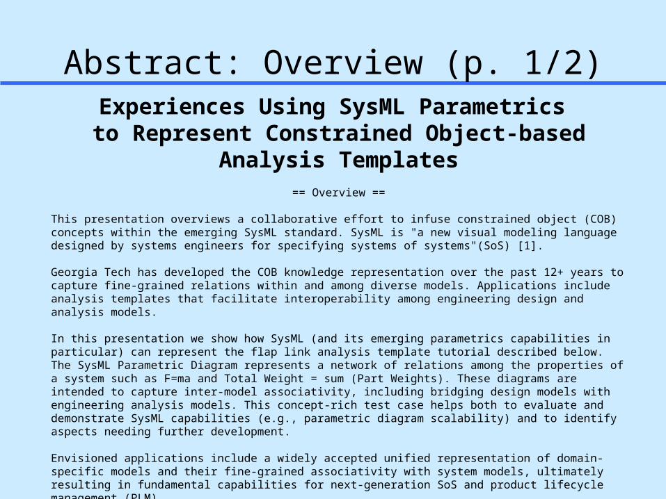
This presentation overviews a collaborative effort to infuse constrained object (COB) concepts within the emerging SysML standard. SysML is "a new visual modeling language designed by systems engineers for specifying systems of systems"(SoS) [1].
Georgia Tech has developed the COB knowledge representation over the past 12+ years to capture fine-grained relations within and among diverse models. Applications include analysis templates that facilitate interoperability among engineering design and analysis models.
In this presentation we show how SysML (and its emerging parametrics capabilities in particular) can represent the flap link analysis template tutorial described below. The SysML Parametric Diagram represents a network of relations among the properties of a system such as F=ma and Total Weight = sum (Part Weights). These diagrams are intended to capture inter-model associativity, including bridging design models with engineering analysis models. This concept-rich test case helps both to evaluate and demonstrate SysML capabilities (e.g., parametric diagram scalability) and to identify aspects needing further development.
Envisioned applications include a widely accepted unified representation of domain-specific models and their fine-grained associativity with system models, ultimately resulting in fundamental capabilities for next-generation SoS and product lifecycle management (PLM).
http://eislab.gatech.edu/pubs/conferences/2005-pde-peak/Keywords: SysML, UML, parametric diagram, constrained object (COB); constraint graph; constraint schematic, design-analysis integration; CAD-CAE interoperability; multi-representation architecture (MRA); simulation-based design (SBD); multi-fidelity; multi-directional; systems of systems (SoS); product lifecycle management (PLM).
Page 3
3
Abstract: Background (p. 2/2)== Constrained Object (COB) and Analysis Template Background [2, 3] ==
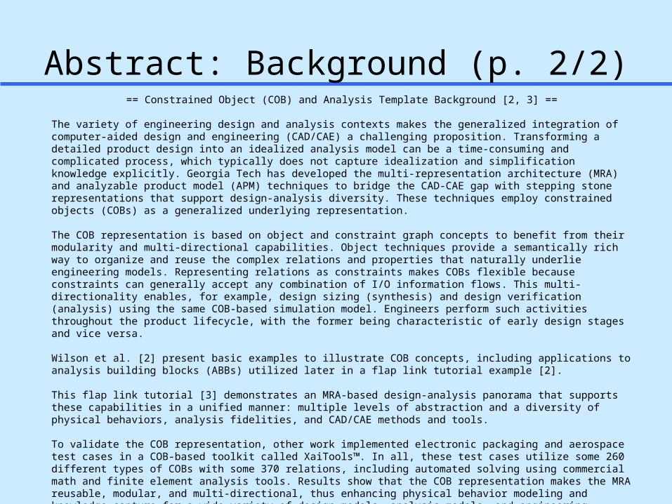
The variety of engineering design and analysis contexts makes the generalized integration of computer-aided design and engineering (CAD/CAE) a challenging proposition. Transforming a detailed product design into an idealized analysis model can be a time-consuming and complicated process, which typically does not capture idealization and simplification knowledge explicitly. Georgia Tech has developed the multi-representation architecture (MRA) and analyzable product model (APM) techniques to bridge the CAD-CAE gap with stepping stone representations that support design-analysis diversity. These techniques employ constrained objects (COBs) as a generalized underlying representation.
The COB representation is based on object and constraint graph concepts to benefit from their modularity and multi-directional capabilities. Object techniques provide a semantically rich way to organize and reuse the complex relations and properties that naturally underlie engineering models. Representing relations as constraints makes COBs flexible because constraints can generally accept any combination of I/O information flows. This multi-directionality enables, for example, design sizing (synthesis) and design verification (analysis) using the same COB-based simulation model. Engineers perform such activities throughout the product lifecycle, with the former being characteristic of early design stages and vice versa.
Wilson et al. [2] present basic examples to illustrate COB concepts, including applications to analysis building blocks (ABBs) utilized later in a flap link tutorial example [2].
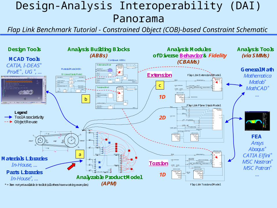
This flap link tutorial [3] demonstrates an MRA-based design-analysis panorama that supports these capabilities in a unified manner: multiple levels of abstraction and a diversity of physical behaviors, analysis fidelities, and CAD/CAE methods and tools.
To validate the COB representation, other work implemented electronic packaging and aerospace test cases in a COB-based toolkit called XaiTools™. In all, these test cases utilize some 260 different types of COBs with some 370 relations, including automated solving using commercial math and finite element analysis tools. Results show that the COB representation makes the MRA reusable, modular, and multi-directional, thus enhancing physical behavior modeling and knowledge capture for a wide variety of design models, analysis models, and engineering computing environments.
References: 1 - http://www.SysML.org/2 - http://eislab.gatech.edu/pubs/conferences/2001-mit-cfsm-1-wilson-cobs/3 - http://eislab.gatech.edu/pubs/conferences/2001-mit-cfsm-2-peak-xai-example/
Page 4
4
Georgia TechCOB/DAI-related Nomenclature
ABB-SMM transformation idealization relation between design and analysis attributes APM-ABB associativity linkage indicating usage of one or more iABB analysis building blockAMCOM U. S. Army Aviation and Missile CommandAPM analyzable product modelCAD computer aided designCAE computer aided engineeringCBAM context-based analysis modelCOB constrained objectCOI constrained object instanceCOS constrained object structureCORBA common ORB architectureDAI design-analysis integrationEIS engineering information systemsESB engineering service bureauFEA finite element analysisFTT fixed topology templateGUI graphical user interfaceIIOP Internet inter-ORB protocolMRA multi-representation architectureORB object request brokerOMG Object Management Group, www.omg.comPWA printed wiring assembly (a PWB populated with components)PWB printed wiring boardSBD simulation-based designSBE simulation-based engineeringSME small-to-medium sized enterprise (small business)SMM solution method modelProAM Product Data-Driven Analysis in a Missile Supply Chain (ProAM) project (AMCOM)PSI Product Simulation Integration project (Boeing)STEP Standard for the Exchange of Product Model Data (ISO 10303).VTMB variable topology multi-bodyXAI X-analysis integration (X= design, mfg., etc.)XCP XaiTools ChipPackage™
XFW XaiTools FrameWork™
XPWAB XaiTools PWA-B™
Page 5
5
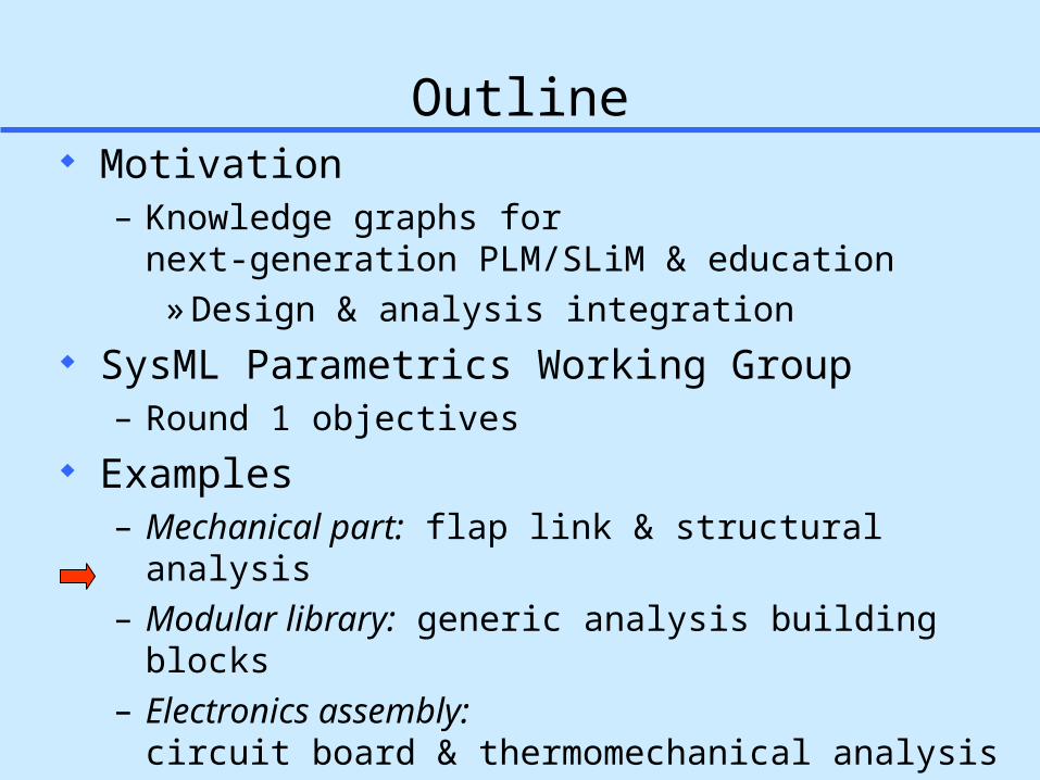
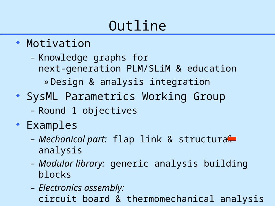
Outline Motivation
– Knowledge graphs for next-generation PLM/SLiM & education
» Design & analysis integration SysML Parametrics Working Group
– Round 1 objectives Examples
– Mechanical part: flap link & structural analysis– Modular library: generic analysis building blocks– Electronics assembly:
circuit board & thermomechanical analysis Results & Summary
Page 6
6
Domain
Abs
tract
ion
Leve
l
Req
uire
men
ts
Sof
twar
e
Ele
ctro
nics
Stru
ctur
es
Systems Engineering
Models of varying abstractions and domains
Legend
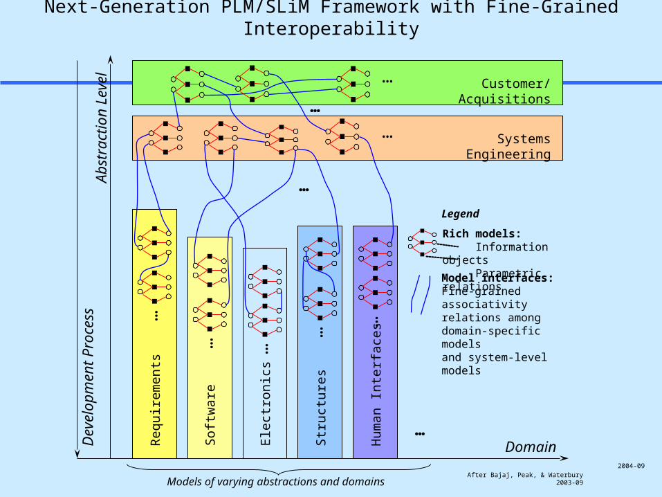
Model interfaces:Fine-grained associativity relations among domain-specific models and system-level models
Dev
elop
men
t Pro
cess
…
Rich models: Information objects Parametric relations
…
…
… …
…
After Bajaj, Peak, & Waterbury2003-09
Next-Generation PLM/SLiM Framework with Fine-Grained Interoperability
Customer/Acquisitions…
…
…
Hum
an In
terfa
ces
…
2004-09
Page 7
7
RR
R
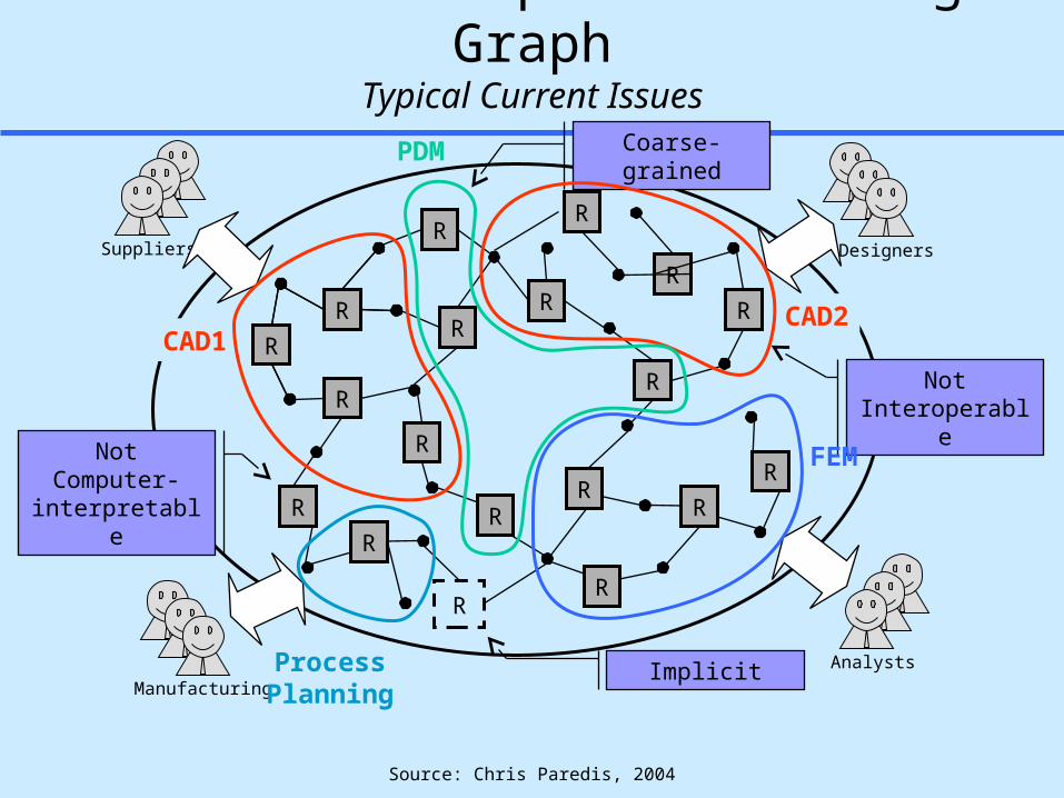
Product Development Knowledge GraphTypical Current Issues
RR
RR
R
RR
DesignersSuppliers
R
RR
RR
R
RR
RR
RR
R R
R
R
R
R
ManufacturingAnalystsImplicit
Not Computer- interpretable
Not Interoperable
Coarse-grainedPDM
CAD1CAD2
FEM
ProcessPlanning
R
Source: Chris Paredis, 2004
Page 8
8
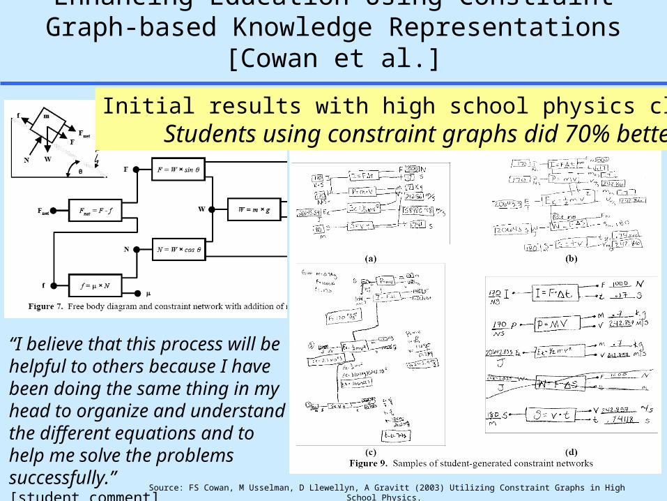
Enhancing Education Using Constraint Graph-based Knowledge Representations [Cowan et al.]
Source: FS Cowan, M Usselman, D Llewellyn, A Gravitt (2003) Utilizing Constraint Graphs in High School Physics. Proc. ASEE Annual Conf. & Expo. http://www.cetl.gatech.edu/services/step/constraint.pdf
“I believe that this process will be helpful to others because I have been doing the same thing in my head to organize and understand the different equations and to help me solve the problems successfully.”[student comment]
Initial results with high school physics class: Students using constraint graphs did 70% better
Page 9
9
SysML Parametrics Working GroupMembers
Manas Bajaj (Georgia Tech) – Implemented circuit board test case in Artisan RtS tool
Roger Burkhart (John Deere) Sandy Friedenthal (Lockheed Martin) – Lead Injoong Kim (Georgia Tech)
– Implemented mechanical part test case in Artisan RtS tool Alan Moore (Artisan) Russell Peak (Georgia Tech) Stephen Waterbury (NASA)
Page 10
10
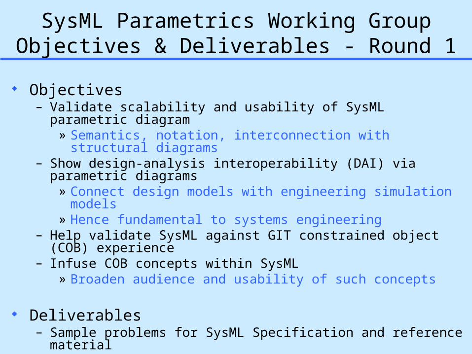
SysML Parametrics Working GroupObjectives & Deliverables - Round 1
Objectives– Validate scalability and usability of SysML parametric diagram
» Semantics, notation, interconnection with structural diagrams– Show design-analysis interoperability (DAI) via parametric diagrams
» Connect design models with engineering simulation models » Hence fundamental to systems engineering
– Help validate SysML against GIT constrained object (COB) experience – Infuse COB concepts within SysML
» Broaden audience and usability of such concepts
Deliverables– Sample problems for SysML Specification and reference material– Initial results of validation effort– Recommended updates/refinements to SysML parametrics capabilities
Page 11
11
Outline Motivation
– Knowledge graphs for next-generation PLM/SLiM & education
» Design & analysis integration SysML Parametrics Working Group
– Round 1 objectives Examples
– Mechanical part: flap link & structural analysis– Modular library: generic analysis building blocks– Electronics assembly:
circuit board & thermomechanical analysis Results & Summary
Page 12
12
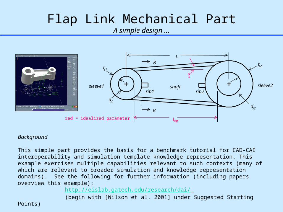
Flap Link Mechanical PartA simple design ...
ts1
B
sleeve1
B ts2
ds2
ds1
sleeve2
L
shaft
Leff
s
rib1 rib2
red = idealized parameter
Background
This simple part provides the basis for a benchmark tutorial for CAD-CAE interoperability and simulation template knowledge representation. This example exercises multiple capabilities relevant to such contexts (many of which are relevant to broader simulation and knowledge representation domains). See the following for further information (including papers overview this example):
http://eislab.gatech.edu/research/dai/ (begin with [Wilson et al. 2001] under Suggested Starting Points)
Page 13
13
Design-Analysis Interoperability (DAI) PanoramaFlap Link Benchmark Tutorial - Constrained Object (COB)-based Constraint Schematic
Material Model ABB:
Continuum ABBs:
E
One D LinearElastic Model
T
G
e
t
material model
polar moment of inertia, Jradius, r
undeformed length, Lo
twist,
theta start, 1
theta end, 2
r1
12
r3
0Lr
JrTr
torque, Tr
xTT
G, r, , ,J
Lo
y
material model
temperature, T
reference temperature, To
force, F
area, A
undeformed length, Lo
total elongation,L
length, L
start, x1
end, x2
E
One D LinearElastic Model
(no shear)
T
e
t
r1
12 xxL
r2
oLLL
r4
AF
edb.r1
oTTT
r3
LL
xFF
E, A,
LLo
T, ,
yL
Torsional Rod
Extensional Rod
temperature change,T
cte,
youngs modulus, E
stress,
shear modulus, G
poissons ratio,
shear stress, shear strain,
thermal strain, t
elastic strain, e
strain,
r2
r1)1(2
EG
r3
r4Tt
Ee
r5
G
te
1D Linear Elastic Model
material
effective length, Leff
linear elastic model
Lo
Extensional Rod(isothermal)
F
L
A
L
E
x2
x1
youngs modulus, E
cross section area, A
al1
al3
al2
linkage
mode: shaft tension
condition reaction
allowable stress
stress mos model
Margin of Safety(> case)
allowableactual
MS
Analysis Modules of Diverse Behavior & Fidelity
(CBAMs) MCAD Tools
Materials LibrariesIn-House, ...
FEA Ansys
Abaqus*
CATIA Elfini*MSC Nastran*
MSC Patran*
...
General MathMathematica
Matlab*
MathCAD*
...
Analyzable Product Model(APM)
Extension
Torsion
1D
1D
Analysis Building Blocks(ABBs)
CATIA, I-DEAS* Pro/E* , UG *, ...
Analysis Tools(via SMMs)
Design Tools
2D
flap_link
critical_section
critical_simple
t2f
wf
tw
hw
t1f
area
effective_length
critical_detailed
stress_strain_model linear_elastic
E
cte area
wf
tw
hw
tf
sleeve_1
b
h
t
b
h
t
sleeve_2
shaft
rib_1
material
rib_2
w
t
r
x
name
t2f
wf
tw
t1f
cross_section
w
t
r
x
R3
R2
R1
R8
R9
R10
6R
R7
R12
11R
1R
2
3
4
5
R
R
R
R
name
linear_elastic_model
wf
tw
tf
inter_axis_length
sleeve_2
shaft
material
linkage
sleeve_1
w
t
r
E
cross_section:basic
w
t
rLws1
ts1
rs2
ws2
ts2
rs2
wf
tw
tf
E
deformation model
x,max
ParameterizedFEA Model
stress mos model
Margin of Safety(> case)
allowableactual
MS
ux mos model
Margin of Safety(> case)
allowableactual
MS
mode: tensionux,max
Fcondition reaction
allowable inter axis length change
allowable stress
ts1
B
sleeve1
B ts2
ds2
ds1
sleeve2
L
shaft
Leff
s
rib1 rib2
material
effective length, Leff
deformation model
linear elastic model
Lo
Torsional Rod
G
J
r
2
1
shear modulus, G
cross section:effective ring polar moment of inertia, J
al1
al3
al2a
linkage
mode: shaft torsion
condition reactionT
outer radius, ro al2b
stress mos model
allowable stress
twist mos model
Margin of Safety(> case)
allowableactual
MS
Margin of Safety(> case)
allowableactual
MS
allowabletwist
Flap Link Extensional Model
Flap Link Plane Strain Model
Flap Link Torsional Model* = Item not yet available in toolkit (all others have working examples)
Parts LibrariesIn-House*, ...
LegendTool AssociativityObject Re-use
c
a
b
Page 14
14
rib tapered_beam
hole
git_lib::git_geometr-y::circle
cross_section
basic_i_section tapered_i_section filleted_tapered_i_section
flap_link
sleeve1
sleeve21
sleeve11
rib21
rib11 shaft
1
1 cross section
1critical_cross_section
1 basic 1 tapered1 design
cls : Flap Link Structure
Flap Link APMSysML Assembly Class Diagram (partial)
ts1
B
sleeve1
B ts2
ds2
ds1
sleeve2
L
shaft
Leff
s
rib1 rib2
red = idealized parameter
ts1
B
sleeve1
B ts2
ds2
ds1
sleeve2
L
shaft
Leff
s
rib1 rib2
red = idealized parameter
Page 15
15
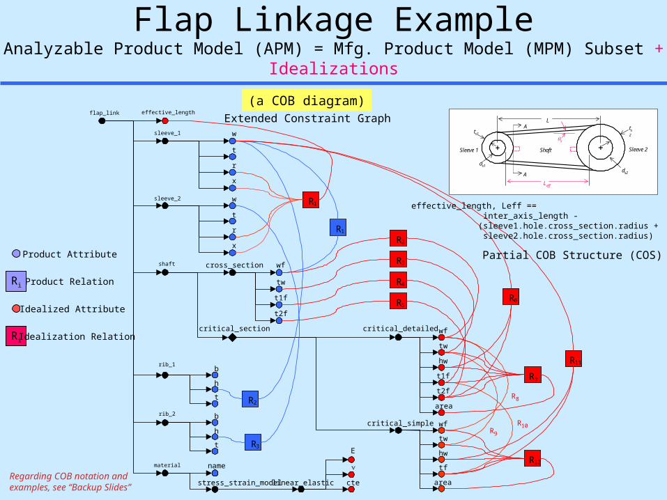
Flap Linkage ExampleAnalyzable Product Model (APM) = Mfg. Product Model (MPM) Subset + Idealizations
flap_link
critical_section
critical_simple
t2f
wf
tw
hw
t1f
area
effective_length
critical_detailed
stress_strain_model linear_elastic
E
cte area
wf
tw
hw
tf
sleeve_1
b
h
t
b
h
t
sleeve_2
shaft
rib_1
material
rib_2
w
t
r
x
name
t2f
wf
tw
t1f
cross_section
w
t
r
x
R3
R2
R1
R8
R9
R10
6R
R7
R12
11R
1R
2
3
4
5
R
R
R
R
ts1
A
Sleeve 1
A ts2
ds2
ds1
Sleeve 2
L
Shaft
Leff
s
Product Attribute
Idealized Attribute
Ri Idealization Relation
Ri Product Relation
Extended Constraint Graph
Partial COB Structure (COS)
effective_length, Leff == inter_axis_length -
(sleeve1.hole.cross_section.radius + sleeve2.hole.cross_section.radius)
Regarding COB notation and examples, see “Backup Slides”
(a COB diagram)
Page 16
16
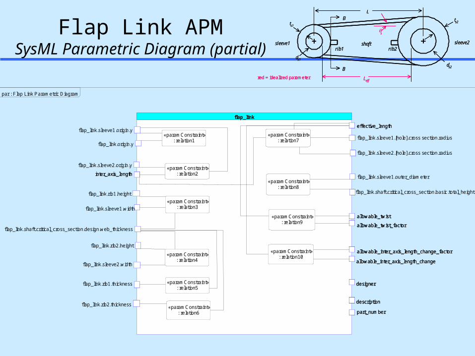
Flap Link APMSysML Parametric Diagram (partial)
ts1
B
sleeve1
B ts2
ds2
ds1
sleeve2
L
shaft
Leff
s
rib1 rib2
red = idealized parameter
ts1
B
sleeve1
B ts2
ds2
ds1
sleeve2
L
shaft
Leff
s
rib1 rib2
red = idealized parameter
flap_linkeffective_length
part_number
inter_axis_length
allowable_twist
allowable_twist_factor
allowable_inter_axis_length_change_factor
allowable_inter_axis_length_change
designer
description
«paramConstraint»: relation1
«paramConstraint»: relation2
«paramConstraint»: relation3
«paramConstraint»: relation4
«paramConstraint»: relation5
«paramConstraint»: relation6
«paramConstraint»: relation7
«paramConstraint»: relation8
«paramConstraint»: relation9
«paramConstraint»: relation10
effective_length
part_number
inter_axis_length
allowable_twist
allowable_twist_factor
allowable_inter_axis_length_change_factor
allowable_inter_axis_length_change
designer
description
«paramConstraint»: relation1
«paramConstraint»: relation2
«paramConstraint»: relation3
«paramConstraint»: relation4
«paramConstraint»: relation5
«paramConstraint»: relation6
«paramConstraint»: relation7
«paramConstraint»: relation8
«paramConstraint»: relation9
«paramConstraint»: relation10
flap_link.sleeve1.origin.y
flap_link.origin.y
flap_link.sleeve2.origin.y
flap_link.rib1.height
flap_link.sleeve1.width
flap_link.shaft.critical_cross_section.design.web_thickness
flap_link.rib2.height
flap_link.sleeve2.width
flap_link.rib1.thickness
flap_link.rib2.thickness
flap_link.sleeve1.[hole].cross section.radius
flap_link.sleeve2.[hole].cross section.radius
flap_link.sleeve1.outer_diameter
flap_link.shaft.critical_cross_section.basic.total_height
par : Flap Link Parametric Diagram
Page 17
17
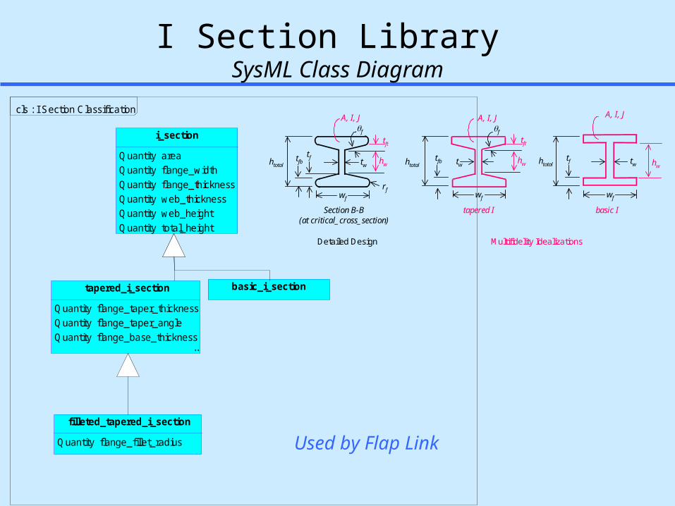
i_section
Quantity areaQuantity flange_widthQuantity flange_thicknessQuantity web_thicknessQuantity web_heightQuantity total_height
basic_i_section
...
filleted_tapered_i_section
Quantity flange_fillet_radius
...
tapered_i_section
Quantity flange_taper_thicknessQuantity flange_taper_angleQuantity flange_base_thickness
cls : I Section Classification
I Section Library SysML Class Diagram
Used by Flap Link
tfb tw
wf
rf
f
Section B-B(at critical_cross_section)
tft
A, I, J
tapered I
htotaltf tw
wf
tfb tw
wf
f
tft
hw hw hw
basic I
htotalhtotal
tf
Multifidelity Idealizations
A, I, J A, I, J
Detailed Design
Page 18
18
filleted_tapered_i_section
flange_fillet_radius
area
flange_thickness
web_height
flange_taper_thickness
flange_taper_angle
flange_base_thickness
flange_width
web_thickness
total_height
flange_fillet_radius
area
flange_thickness
web_height
flange_taper_thickness
flange_taper_angle
flange_base_thickness
flange_width
web_thickness
total_height
tapered_i_section
flange_taper_thickness
flange_taper_angle
flange_base_thickness
flange_width
web_thickness
total_height
«paramConstraint»: relation13
«paramConstraint»: relation14
total_height
flange_width
flange_thickness
web_thickness
area
web_height
flange_taper_thickness
flange_taper_angle
flange_base_thickness
flange_width
web_thickness
total_height
«paramConstraint»: relation13
«paramConstraint»: relation14
total_height
flange_width
flange_thickness
web_thickness
area
web_height
basic_i_section
«paramConstraint»: relation13
area
flange_width
flange_thickness
web_thickness
web_height
total_height
«paramConstraint»: relation13
area
flange_width
flange_thickness
web_thickness
web_height
total_height
«paramConstraint»relation8
«paramConstraint»relation9
«paramConstraint»relation10
«paramConstraint»relation11
«paramConstraint»relation12
«paramConstraint»relation13
«paramConstraint»relation14
«paramConstraint»relation15
«paramConstraint»relation16
«paramConstraint»relation17
asm : Cross Section Assembly Diagram
I Section Library SysML Parametric Diagram
ParametricParametric
Page 19
19
Outline Motivation
– Knowledge graphs for next-generation PLM/SLiM & education
» Design & analysis integration SysML Parametrics Working Group
– Round 1 objectives Examples
– Mechanical part: flap link & structural analysis– Modular library: generic analysis building blocks– Electronics assembly:
circuit board & thermomechanical analysis Results & Summary
Page 20
20Engineering Information Systems Lab eislab.gatech.edu© 1993-2005 GTRC
Design-Analysis Interoperability (DAI) PanoramaFlap Link Benchmark Tutorial - Constrained Object (COB)-based Constraint Schematic
Material Model ABB:
Continuum ABBs:
E
One D LinearElastic Model
T
G
e
t
material model
polar moment of inertia, Jradius, r
undeformed length, Lo
twist,
theta start, 1
theta end, 2
r1
12
r3
0Lr
JrTr
torque, Tr
xTT
G, r, , ,J
Lo
y
material model
temperature, T
reference temperature, To
force, F
area, A
undeformed length, Lo
total elongation,L
length, L
start, x1
end, x2
E
One D LinearElastic Model
(no shear)
T
e
t
r1
12 xxL
r2
oLLL
r4
AF
edb.r1
oTTT
r3
LL
xFF
E, A,
LLo
T, ,
yL
Torsional Rod
Extensional Rod
temperature change,T
cte,
youngs modulus, E
stress,
shear modulus, G
poissons ratio,
shear stress, shear strain,
thermal strain, t
elastic strain, e
strain,
r2
r1)1(2
EG
r3
r4Tt
Ee
r5
G
te
1D Linear Elastic Model
material
effective length, Leff
linear elastic model
Lo
Extensional Rod(isothermal)
F
L
A
L
E
x2
x1
youngs modulus, E
cross section area, A
al1
al3
al2
linkage
mode: shaft tension
condition reaction
allowable stress
stress mos model
Margin of Safety(> case)
allowableactual
MS
Analysis Modules of Diverse Behavior & Fidelity
(CBAMs) MCAD Tools
Materials LibrariesIn-House, ...
FEA Ansys
Abaqus*
CATIA Elfini*MSC Nastran*
MSC Patran*
...
General MathMathematica
Matlab*
MathCAD*
...
Analyzable Product Model(APM)
Extension
Torsion
1D
1D
Analysis Building Blocks(ABBs)
CATIA, I-DEAS* Pro/E* , UG *, ...
Analysis Tools(via SMMs)
Design Tools
2D
flap_link
critical_section
critical_simple
t2f
wf
tw
hw
t1f
area
effective_length
critical_detailed
stress_strain_model linear_elastic
E
cte area
wf
tw
hw
tf
sleeve_1
b
h
t
b
h
t
sleeve_2
shaft
rib_1
material
rib_2
w
t
r
x
name
t2f
wf
tw
t1f
cross_section
w
t
r
x
R3
R2
R1
R8
R9
R10
6R
R7
R12
11R
1R
2
3
4
5
R
R
R
R
name
linear_elastic_model
wf
tw
tf
inter_axis_length
sleeve_2
shaft
material
linkage
sleeve_1
w
t
r
E
cross_section:basic
w
t
rLws1
ts1
rs2
ws2
ts2
rs2
wf
tw
tf
E
deformation model
x,max
ParameterizedFEA Model
stress mos model
Margin of Safety(> case)
allowableactual
MS
ux mos model
Margin of Safety(> case)
allowableactual
MS
mode: tensionux,max
Fcondition reaction
allowable inter axis length change
allowable stress
ts1
B
sleeve1
B ts2
ds2
ds1
sleeve2
L
shaft
Leff
s
rib1 rib2
material
effective length, Leff
deformation model
linear elastic model
Lo
Torsional Rod
G
J
r
2
1
shear modulus, G
cross section:effective ring polar moment of inertia, J
al1
al3
al2a
linkage
mode: shaft torsion
condition reactionT
outer radius, ro al2b
stress mos model
allowable stress
twist mos model
Margin of Safety(> case)
allowableactual
MS
Margin of Safety(> case)
allowableactual
MS
allowabletwist
Flap Link Extensional Model
Flap Link Plane Strain Model
Flap Link Torsional Model* = Item not yet available in toolkit (all others have working examples)
Parts LibrariesIn-House*, ...
LegendTool AssociativityObject Re-use
c
b
a
Page 21
21
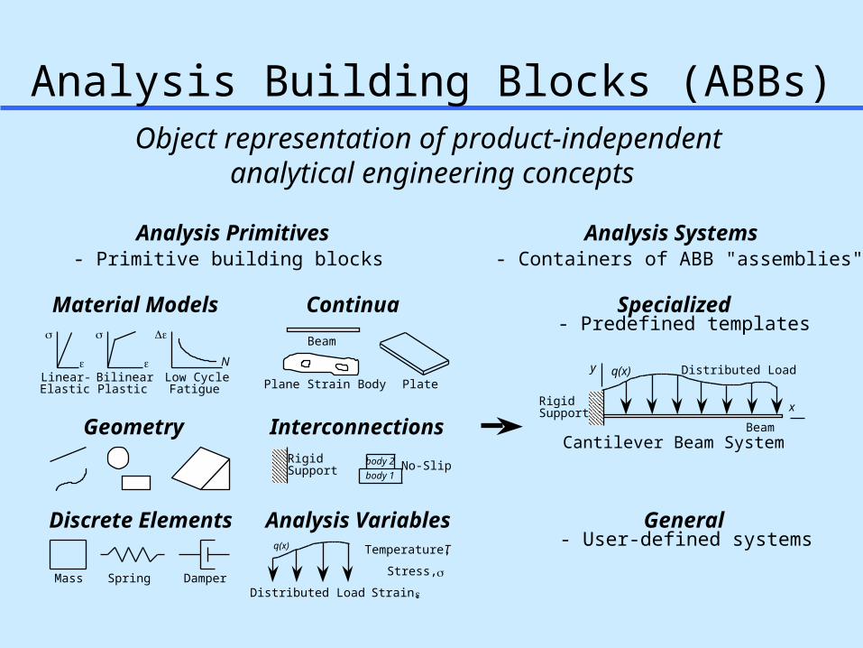
Analysis Building Blocks (ABBs)
Analysis Primitives
Beam
q(x)
Distributed Load
RigidSupport
Cantilever Beam System
Analysis Systems- Primitive building blocks - Containers of ABB "assemblies"
Material Models
Specialized
General
- Predefined templates
- User-defined systemsAnalysis VariablesDiscrete Elements
Interconnections
Continua
Plane Strain BodyLinear-Elastic
BilinearPlastic PlateLow Cycle
Fatigue
N
Mass Spring Damper
x
y q(x)
Beam
Distributed Load
RigidSupport
No-Slipbody 1body 2
Temperature,
Stress,
Strain,
T
Geometry
Object representation of product-independent analytical engineering concepts
Page 22
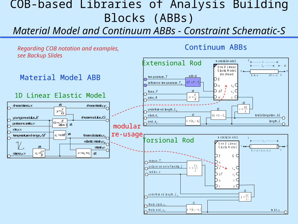
22
COB-based Libraries of Analysis Building Blocks (ABBs)Material Model and Continuum ABBs - Constraint Schematic-S
Material Model ABB
Continuum ABBs
modularre-usage
E
O n e D L i n e a rE la s t i c M o d e l
T
G
e
t
m a t e r i a l m o d e l
p o l a r m o m e n t o f i n e r t i a , Jr a d iu s , r
u n d e f o r m e d l e n g t h , L o
t w i s t ,
t h e t a s t a r t , 1
t h e t a e n d , 2
r 1
12
r 3
0Lr
JrT r
t o r q u e , T r
xTT
G , r , , ,J
L o
y
m ateria l m odel
tem perature, T
re ference tem perature, T o
force, F
area, A
undefo rm ed length, L o
to ta l e longation,L
length, L
start, x 1
end, x 2
E
O ne D LinearE lastic M odel
(no shear)
T
e
t
r1
12 xxL
r2
oLLL
r4
AF
edb.r1
oTTT
r3
LL
xFF
E, A ,
LL o
T , ,
yL
Torsional Rod
Extensional Rod
temperature change,T
cte,
youngs modulus, E
stress,
shear modulus, G
poissons ratio,
shear stress, shear strain,
thermal strain, telastic strain, e
strain,
r2
r1)1(2
EG
r3
r4Tt
Ee
r5
G
te
1D Linear Elastic Model
Regarding COB notation and examples, see Backup Slides
Page 23
23
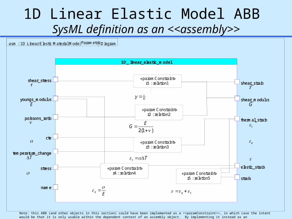
1D Linear Elastic Model ABB SysML definition as an <<assembly>>
Note: this ABB (and other objects in this section) could have been implemented as a <<paramConstraint>>, in which case the intent would be that it is only usable within the dependent context of an assembly object. By implementing it instead as an <<assembly>>, it may be used as an independent object, or optionally in a dependent manner.
1D_ linear_elastic_model
«paramConstraint»r1 : relation1
«paramConstraint»r2 : relation2
«paramConstraint»r3 : relation3
«paramConstraint»r4 : relation4 «paramConstraint»
r5 : relation5
elastic_strain
temperature_change
youngs_modulus
stress
cte
poissons_ratio thermal_strain
strain
shear_modulus
shear_stress shear_strain
name
E
T
G
t
e
G
)1(2
EG
Tt
Ee
te
asm : 1D Linear Elastic Material Model Assembly DiagramParametricParametric
Page 24
24
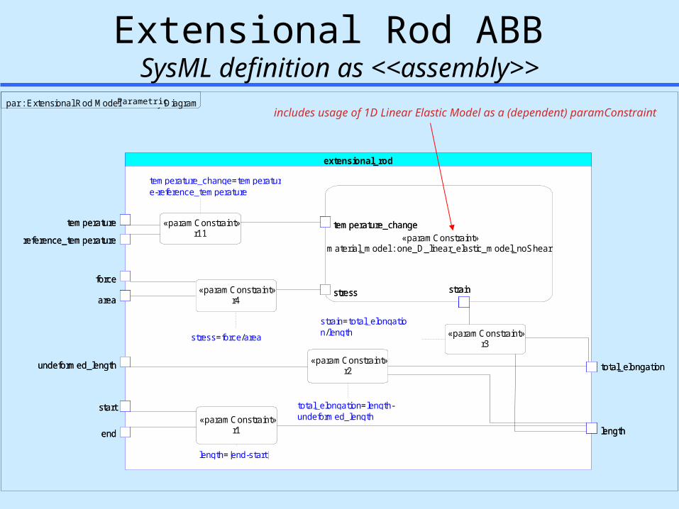
Extensional Rod ABB SysML definition as <<assembly>>
includes usage of 1D Linear Elastic Model as a (dependent) paramConstraint
extensional_rod
«paramConstraint»material_model : one_D_linear_elastic_model_noShear
temperature_change
stress strain
«paramConstraint»r1
«paramConstraint»r2
«paramConstraint»r3
«paramConstraint»r4
temperature
reference_temperature
force
area
undeformed_length
start
end
total_elongation
length
«paramConstraint»r11 «paramConstraint»
material_model : one_D_linear_elastic_model_noShear
temperature_change
stress strain
temperature_change
stress strain
«paramConstraint»r1
«paramConstraint»r2
«paramConstraint»r3
«paramConstraint»r4
temperature
reference_temperature
force
area
undeformed_length
start
end
total_elongation
length
«paramConstraint»r11
strain=total_elongation/length
total_elongation=length-undeformed_length
length=|end-start|
stress=force/area
temperature_change=temperature-reference_temperature
par : Extensional Rod Model Assembly DiagramParametric
Page 25
25
Outline Motivation
– Knowledge graphs for next-generation PLM/SLiM & education
» Design & analysis integration SysML Parametrics Working Group
– Round 1 objectives Examples
– Mechanical part: flap link & structural analysis– Modular library: generic analysis building blocks– Electronics assembly:
circuit board & thermomechanical analysis Results & Summary
Page 26
26
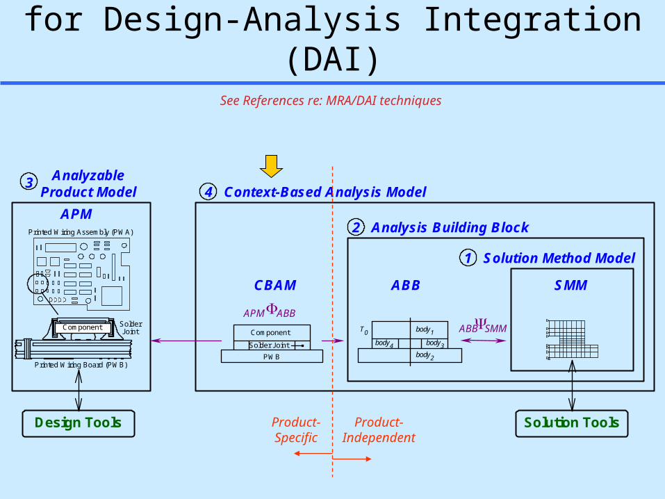
Multi-Representation Architecture (MRA)for Design-Analysis Integration (DAI)
1 Solution Method Model
ABB SMM
2 Analysis Building Block
4 Context-Based Analysis Model3
SMMABBAPM ABB
CBAM
APM
Design Tools Solution Tools
Printed Wiring Assembly (PWA)
Solder Joint
Component
PWB
body3body2
body1body4
T0
Printed Wiring Board (PWB)
SolderJointComponent
AnalyzableProduct Model
Product-Specific
Product-Independent
See References re: MRA/DAI techniques
Page 27
27
Design-Analysis Interoperability (DAI) PanoramaFlap Link Benchmark Tutorial - Constrained Object (COB)-based Constraint Schematic
Material Model ABB:
Continuum ABBs:
E
One D LinearElastic Model
T
G
e
t
material model
polar moment of inertia, Jradius, r
undeformed length, Lo
twist,
theta start, 1
theta end, 2
r1
12
r3
0Lr
JrTr
torque, Tr
xTT
G, r, , ,J
Lo
y
material model
temperature, T
reference temperature, To
force, F
area, A
undeformed length, Lo
total elongation,L
length, L
start, x1
end, x2
E
One D LinearElastic Model
(no shear)
T
e
t
r1
12 xxL
r2
oLLL
r4
AF
edb.r1
oTTT
r3
LL
xFF
E, A,
LLo
T, ,
yL
Torsional Rod
Extensional Rod
temperature change,T
cte,
youngs modulus, E
stress,
shear modulus, G
poissons ratio,
shear stress, shear strain,
thermal strain, t
elastic strain, e
strain,
r2
r1)1(2
EG
r3
r4Tt
Ee
r5
G
te
1D Linear Elastic Model
material
effective length, Leff
linear elastic model
Lo
Extensional Rod(isothermal)
F
L
A
L
E
x2
x1
youngs modulus, E
cross section area, A
al1
al3
al2
linkage
mode: shaft tension
condition reaction
allowable stress
stress mos model
Margin of Safety(> case)
allowableactual
MS
Analysis Modules of Diverse Behavior & Fidelity
(CBAMs) MCAD Tools
Materials LibrariesIn-House, ...
FEA Ansys
Abaqus*
CATIA Elfini*MSC Nastran*
MSC Patran*
...
General MathMathematica
Matlab*
MathCAD*
...
Analyzable Product Model(APM)
Extension
Torsion
1D
1D
Analysis Building Blocks(ABBs)
CATIA, I-DEAS* Pro/E* , UG *, ...
Analysis Tools(via SMMs)
Design Tools
2D
flap_link
critical_section
critical_simple
t2f
wf
tw
hw
t1f
area
effective_length
critical_detailed
stress_strain_model linear_elastic
E
cte area
wf
tw
hw
tf
sleeve_1
b
h
t
b
h
t
sleeve_2
shaft
rib_1
material
rib_2
w
t
r
x
name
t2f
wf
tw
t1f
cross_section
w
t
r
x
R3
R2
R1
R8
R9
R10
6R
R7
R12
11R
1R
2
3
4
5
R
R
R
R
name
linear_elastic_model
wf
tw
tf
inter_axis_length
sleeve_2
shaft
material
linkage
sleeve_1
w
t
r
E
cross_section:basic
w
t
rLws1
ts1
rs2
ws2
ts2
rs2
wf
tw
tf
E
deformation model
x,max
ParameterizedFEA Model
stress mos model
Margin of Safety(> case)
allowableactual
MS
ux mos model
Margin of Safety(> case)
allowableactual
MS
mode: tensionux,max
Fcondition reaction
allowable inter axis length change
allowable stress
ts1
B
sleeve1
B ts2
ds2
ds1
sleeve2
L
shaft
Leff
s
rib1 rib2
material
effective length, Leff
deformation model
linear elastic model
Lo
Torsional Rod
G
J
r
2
1
shear modulus, G
cross section:effective ring polar moment of inertia, J
al1
al3
al2a
linkage
mode: shaft torsion
condition reactionT
outer radius, ro al2b
stress mos model
allowable stress
twist mos model
Margin of Safety(> case)
allowableactual
MS
Margin of Safety(> case)
allowableactual
MS
allowabletwist
Flap Link Extensional Model
Flap Link Plane Strain Model
Flap Link Torsional Model* = Item not yet available in toolkit (all others have working examples)
Parts LibrariesIn-House*, ...
LegendTool AssociativityObject Re-use
c
b
a
Page 28
28
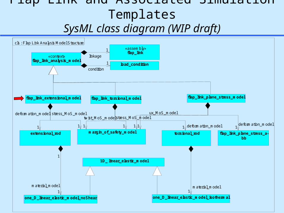
Flap Link and Associated Simulation TemplatesSysML class diagram (WIP draft)
1D_ linear_elastic_model
one_D_linear_elastic_model_noShear one_D_linear_elastic_model_isothermal
load_condition
flap_link_extensional_model
«assembly»flap_link
extensional_rod margin_of_safety_model
«context»flap_link_analysis_model
flap_link_torsional_model flap_link_plane_stress_model
torsional_rod flap_link_plane_stress_a-bb
1 deformation_model1
stress_MoS_model
1deformation_model11
ux_MoS_model
1material_model
1condition
1linkage
1
deformation_model
1
stress_MoS_model
1
twist_MoS_model
1
1
material_model
cls : Flap Link Analysis Model Structure
Page 29
29
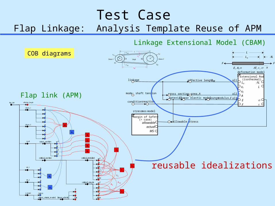
Test Case Flap Linkage: Analysis Template Reuse of APM
Linkage Extensional Model (CBAM)
material
effective length, Leff
deformation model
linear elastic model
Lo
Extensional Rod(isothermal)
F
L
A
L
E
x2
x1
youngs modulus, Ecross section area, A
al1
al3
al2
linkage
mode: shaft tension
condition reaction
allowable stress
ts1
A
Sleeve 1
A ts2
ds2
ds1
Sleeve 2
L
Shaft
Leff
s
stress mos model
Margin of Safety(> case)
allowableactual
MS
xFF
E, A,
LLo
T, ,
L
flap_link
critical_section
critical_simple
t2f
wf
tw
hw
t1f
area
effective_length
critical_detailed
stress_strain_model linear_elastic
E
cte area
wf
tw
hw
tf
sleeve_1
b
h
t
b
h
t
sleeve_2
shaft
rib_1
material
rib_2
w
t
r
x
name
t2f
wf
tw
t1f
cross_section
w
t
r
x
R3
R2
R1
R8
R9
R10
6R
R7
R12
11R
1R
2
3
4
5
R
R
R
R
Flap link (APM)
reusable idealizations
COB diagrams
Page 30
30
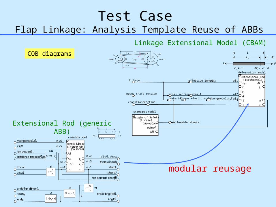
Test Case Flap Linkage: Analysis Template Reuse of ABBs
modular reusage
Extensional Rod (generic ABB)
Linkage Extensional Model (CBAM)
E
One D Linear
(no shear)
T
e
t
temperature change,T
material model
temperature, T
reference temperature, To
cte,
youngs modulus, E
force, F
area, A stress,
undeformed length, Lo
strain,
total elongation,L
length, Lstart, x1
end, x2
mv6
mv5
smv1
mv1mv4
thermal strain, t
elastic strain, e
mv3
mv2
xFF
E, A,
LLo
T, ,
yL
r1
12 xxL
r2
oLLL
r4
AF
sr1
oTTT
r3LL
Elastic Model
material
effective length, Leff
deformation model
linear elastic model
Lo
Extensional Rod(isothermal)
F
L
A
L
E
x2
x1
youngs modulus, Ecross section area, A
al1
al3
al2
linkage
mode: shaft tension
condition reaction
allowable stress
ts1
A
Sleeve 1
A ts2
ds2
ds1
Sleeve 2
L
Shaft
Leff
s
stress mos model
Margin of Safety(> case)
allowableactual
MS
xFF
E, A,
LLo
T, ,
LCOB diagrams
Page 31
31
Flap Link Simulation Template: Extensional ModelSysML parametric diagram (definition) - dot notation view
Caveat: materialModel properties would be better exposed as promoted ports on extensional_rod
«paramConstraint»load_condition
reaction
load
reaction
load
«paramConstraint»margin_of_safety_model
margin_of_safety allowable
determined
margin_of_safety allowable
determined
«paramConstraint»extensional_rod
area
undeformed_length
start
end
length
temperature
reference_temperature
force
«paramConstraint»material_model : one_D_linear_elastic_model_noShear
name
youngs_modulus
stress
total_elongation
area
undeformed_length
start
end
length
temperature
reference_temperature
force
«paramConstraint»material_model : one_D_linear_elastic_model_noShear
name
youngs_modulus
stress
name
youngs_modulus
stress
total_elongation
«paramConstraint»relation11
«paramConstraint»relation12
«paramConstraint»relation13
«paramConstraint»relation14
«paramConstraint»relation16
«paramConstraint»relation17
«paramConstraint»relation15
flap_link.effective_length
flap_link.shaft.critical_cross_section.basic.area
flap_link.[material].stress_strain_model.linear_elastic.youngs_modulus
flap_link.[material].yield_stress
flap_link.[material].name
asm : Flap Link Extensional Model Assembly DiagramParametricParametric
Page 32
32
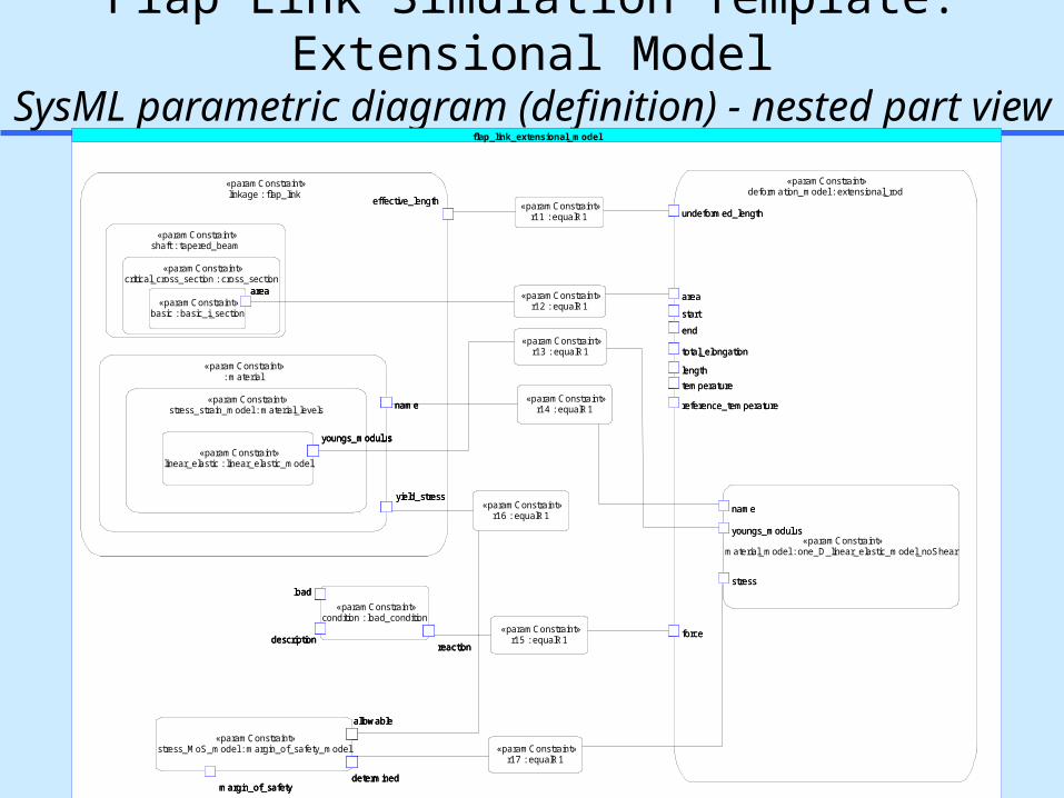
Flap Link Simulation Template: Extensional ModelSysML parametric diagram (definition) - nested part view
flap_link_extensional_model
«paramConstraint»stress_MoS_model : margin_of_safety_model
allowable
determinedmargin_of_safety
«paramConstraint»deformation_model : extensional_rod
«paramConstraint»material_model : one_D_linear_elastic_model_noShear
name
youngs_modulus
stress
undeformed_length
length
area
start
end
total_elongation
reference_temperature
force
temperature
«paramConstraint»condition : load_condition
reactiondescription
load
«paramConstraint»linkage : flap_link
«paramConstraint»shaft : tapered_beam
«paramConstraint»critical_cross_section : cross_section
«paramConstraint»basic : basic_i_section
area
«paramConstraint»: material
«paramConstraint»stress_strain_model : material_levels
«paramConstraint»linear_elastic : linear_elastic_model
youngs_modulus
yield_stress
name
effective_length «paramConstraint»r11 : equalR1
«paramConstraint»r12 : equalR1
«paramConstraint»r13 : equalR1
«paramConstraint»r14 : equalR1
«paramConstraint»r15 : equalR1
«paramConstraint»r16 : equalR1
«paramConstraint»r17 : equalR1
«paramConstraint»stress_MoS_model : margin_of_safety_model
allowable
determinedmargin_of_safety
allowable
determinedmargin_of_safety
«paramConstraint»deformation_model : extensional_rod
«paramConstraint»material_model : one_D_linear_elastic_model_noShear
name
youngs_modulus
stress
undeformed_length
length
area
start
end
total_elongation
reference_temperature
force
temperature
«paramConstraint»material_model : one_D_linear_elastic_model_noShear
name
youngs_modulus
stress
name
youngs_modulus
stress
undeformed_length
length
area
start
end
total_elongation
reference_temperature
force
temperature
«paramConstraint»condition : load_condition
reactiondescription
load
reactiondescription
load
«paramConstraint»linkage : flap_link
«paramConstraint»shaft : tapered_beam
«paramConstraint»critical_cross_section : cross_section
«paramConstraint»basic : basic_i_section
area
«paramConstraint»: material
«paramConstraint»stress_strain_model : material_levels
«paramConstraint»linear_elastic : linear_elastic_model
youngs_modulus
yield_stress
name
effective_length
«paramConstraint»shaft : tapered_beam
«paramConstraint»critical_cross_section : cross_section
«paramConstraint»basic : basic_i_section
area
«paramConstraint»critical_cross_section : cross_section
«paramConstraint»basic : basic_i_section
area«paramConstraint»
basic : basic_i_section
areaarea
«paramConstraint»: material
«paramConstraint»stress_strain_model : material_levels
«paramConstraint»linear_elastic : linear_elastic_model
youngs_modulus
yield_stress
name«paramConstraint»stress_strain_model : material_levels
«paramConstraint»linear_elastic : linear_elastic_model
youngs_modulus«paramConstraint»
linear_elastic : linear_elastic_model
youngs_modulusyoungs_modulus
yield_stress
name
effective_length «paramConstraint»r11 : equalR1
«paramConstraint»r12 : equalR1
«paramConstraint»r13 : equalR1
«paramConstraint»r14 : equalR1
«paramConstraint»r15 : equalR1
«paramConstraint»r16 : equalR1
«paramConstraint»r17 : equalR1
Page 33
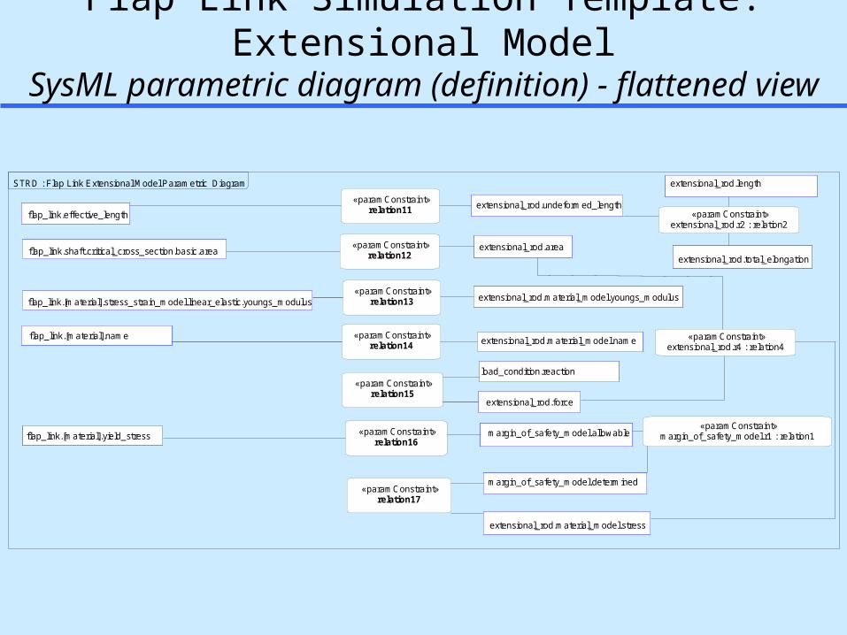
33
Flap Link Simulation Template: Extensional ModelSysML parametric diagram (definition) - flattened view
«paramConstraint»relation14
«paramConstraint»relation15
«paramConstraint»relation16
«paramConstraint»relation17
«paramConstraint»relation11
«paramConstraint»relation12
«paramConstraint»relation13
extensional_rod.total_elongation
flap_link.effective_lengthextensional_rod.undeformed_length
extensional_rod.areaflap_link.shaft.critical_cross_section.basic.area
flap_link.[material].stress_strain_model.linear_elastic.youngs_modulus extensional_rod.material_model.youngs_modulus
flap_link.[material].name extensional_rod.material_model.name
extensional_rod.force
load_condition.reaction
flap_link.[material].yield_stress margin_of_safety_model.allowable
extensional_rod.material_model.stress
margin_of_safety_model.determined
«paramConstraint»extensional_rod.r2 : relation2
«paramConstraint»extensional_rod.r4 : relation4
«paramConstraint»margin_of_safety_model.r1 : relation1
extensional_rod.lengthSTRD : Flap Link Extensional Model Parametric Diagram
Page 34
34
material
effective length, Leff
deformation model
linear elastic model
Lo
Extensional Rod(isothermal)
F
L
A
L
E
x2
x1
youngs modulus, E
shaftcritical_cross
_section
al1
al3
al2
linkage
mode: shaft tension
condition reaction
allowable stress
stress mos model
Margin of Safety(> case)
allowableactual
MS
description
area, Abasic
example 1, state 1
steel
10000 lbs
flaps mid position
1.125 in2
18000 psi
30e6 psi
1.025
5.0 in
8888 psi
1.43e-3 inFlap Link #3
material
effective length, Leff
deformation model
linear elastic model
Lo
Extensional Rod(isothermal)
F
L
A
L
E
x2
x1
youngs modulus, E
shaftcritical_cross_section
al1
al3
al2
linkage
mode: shaft tension
condition reaction
allowable stress
stress mos model
Margin of Safety(> case)
allowableactual
MS
description
area, AbasicX
3.00e-3 in
1.125 in2
5.0 inFlap Link #3
0.0
steel10000 lbs
flaps mid position
18000psi
example 1, state 3
30e6 psi18000 psi
0.555 in2
Flap Linkage Instancewith Multi-Directional I/O States
Design Verification- Input: design details- Output: i) idealized design parameters ii) physical response criteria
Design Synthesis- Input: desired physical response criteria- Output: i) idealized design parameters (e.g., for sizing), or ii) detailed design parameters
COB diagrams
Page 35
35
Flap Link Extensional ModelExample COB Instance in XaiTools (object-oriented spreadsheet)
Detailed CAD datafrom CATIA
Idealized analysis features in APM
Explicit multi-directional associativity between design & analysis
Modular generic analysis templates(ABBs)
Library data for materials
Focus Point ofCAD-CAE Integration
example 1, state 1
Page 36
36
«paramConstraint»margin_of_safety_model
margin_of_safety = ?allowable = ?
determined = ?margin_of_safety = ?
allowable = ?
determined = ?
«paramConstraint»extensional_rod
area = ?
undeformed_length = ?
start
end
length
temperature
reference_temperature
force = ?
«paramConstraint»material_model : one_D_linear_elastic_model_noShear
name = ?
youngs_modulus = ?
stress = ?
total_elongation
area = ?
undeformed_length = ?
start
end
length
temperature
reference_temperature
force = ?
«paramConstraint»material_model : one_D_linear_elastic_model_noShear
name = ?
youngs_modulus = ?
stress = ?
name = ?
youngs_modulus = ?
stress = ?
total_elongation
«paramConstraint»relation11
«paramConstraint»relation12
«paramConstraint»relation13
«paramConstraint»relation14
«paramConstraint»relation16
«paramConstraint»relation17
«paramConstraint»relation15
«paramConstraint»load_condition
reaction = 10000
load
reaction = 10000
load
flap_link.shaft.critical_cross_section.basic.area = 1.125
flap_link.[material].stress_strain_model.linear_elastic.youngs_modulus = 30e6
flap_link.[material].name = steel
flap_link.[material].yield_stress = 18000
flap_link.effective_length = 5.0 5.0
1.125
10000
30e6
steel
88888888
1.025
example : Flap Link Extensional Model State 1.1
Flap Link Extensional Model - Usage: Solved StateSysML parametric diagram (instance)
Page 37
37
Outline Motivation
– Knowledge graphs for next-generation PLM/SLiM & education
» Design & analysis integration SysML Parametrics Working Group
– Round 1 objectives Examples
– Mechanical part: flap link & structural analysis– Modular library: generic analysis building blocks– Electronics assembly:
circuit board & thermomechanical analysis Results & Summary
Page 38
38
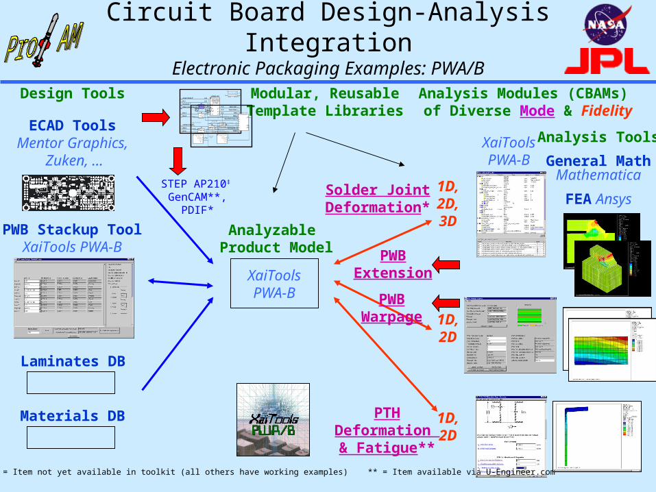
Circuit Board Design-Analysis IntegrationElectronic Packaging Examples: PWA/B
Analysis Modules (CBAMs) of Diverse Mode & Fidelity
Design Tools
Laminates DB
FEA Ansys
General MathMathematica
Analyzable Product Model
XaiToolsPWA-B
XaiToolsPWA-B
Solder JointDeformation*
PTHDeformation & Fatigue**
1D,2D
1D,2D,3D
Modular, ReusableTemplate Libraries
ECAD Tools Mentor Graphics,
Zuken, …
temperature change,T
material model
temperature, T
reference temperature, To
cte,
youngs modulus, E
force, F
area, A stress,
undeformed length, Lo
strain,
total elongation,L
length, L
start, x1
end, x2
mv6
mv5
smv1
mv1mv4
E
One D LinearElastic Model(no shear)
T
et
thermal strain, t
elastic strain, e
mv3
mv2
xFF
E, A,
LLo
T, ,
yL
r1
12 xxL
r2
oLLL
r4
AF
sr1
oTTT
r3LL
m a t e r ia l
e f f e c t i v e l e n g t h , L e f f
d e f o rm a t i o n m o d e l
l i n e a r e l a s t i c m o d e l
L o
T o rs i o n a l R o d
G
J
r
2
1
s h e a r m o d u l u s , G
c ro s s s e c t io n :e f f e c t i v e r i n g p o l a r m o m e n t o f i n e r t i a , J
a l 1
a l 3
a l 2 a
li n k a g e
m o d e : s h a f t t o r s i o n
c o n d i t i o n re a c t i o n
t s1
A
S le e v e 1
A t s2
d s2
d s1
S l ee v e 2
L
S h a f t
L ef f
s
T
o u t e r r a d i u s , r o a l 2 b
s t r e s s m o s m o d e l
a l l o w a b le s t r e s s
t w i s t m o s m o d e l
M a r g i n o f S a f e t y( > c a s e )
a l l o w a b lea c t u a l
M S
M a rg i n o f S a f e t y( > c a s e )
a l l o w a b l ea c t u a l
M S
a l lo w a b l et w i s t Analysis Tools
PWBExtension
1D,2D
Materials DB
PWB Stackup ToolXaiTools PWA-B
STEP AP210‡
GenCAM**,PDIF*
‡ AP210 WD48 * = Item not yet available in toolkit (all others have working examples) ** = Item available via U-Engineer.com
PWBWarpage
Page 39
39
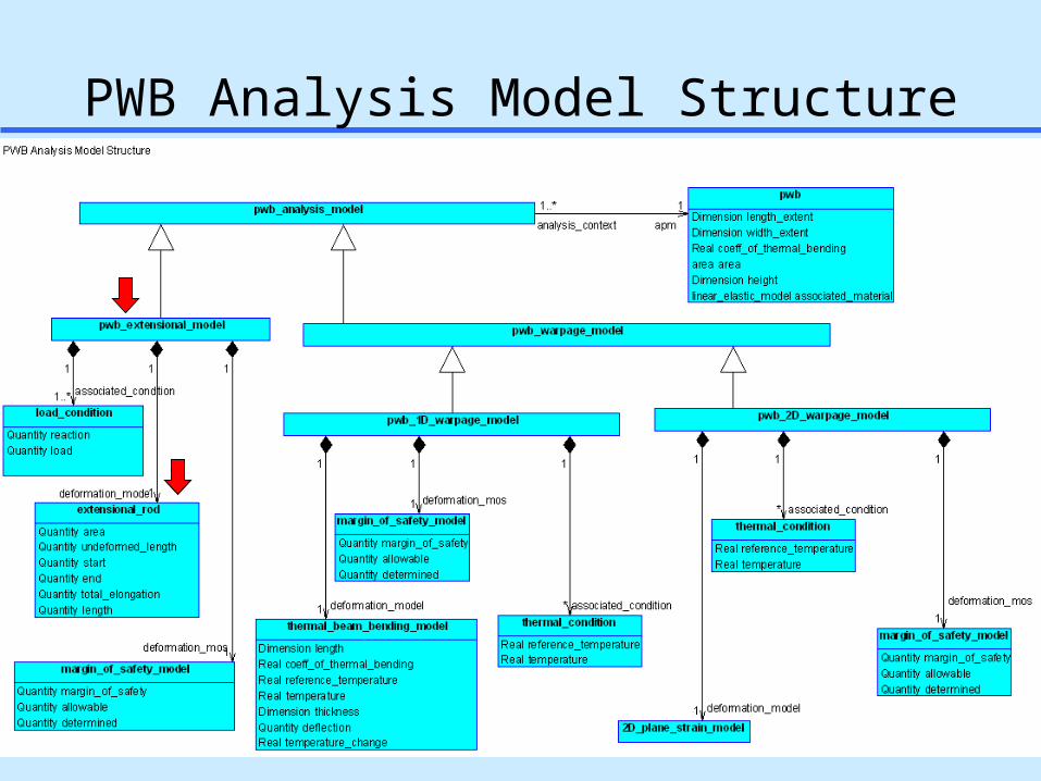
PWB Analysis Model Structure
Page 40
40
PWB Extensional Rod Model SysML Parametric Diagram
Parameters from the PWB APM
Same generic analysis building block (ABB) used by flap link
Page 41
41
total_thicknesspwa
layup layers[0]
layers[1]
layers[2]
TOTAL
CU1T
CU2T
POLYT
PREPREGT
TETRA1T
EXCU
ALPXCU
EXEPGL
ALPXEGL
TO
deformation modelParameterized
FEA Model
ux mos model
Margin of Safety(> case)
allowableactual
MS
UX
condition
UY
SX
associated_pwb
nominal_thickness
prepregs[0] nominal_thickness
top_copper_layer nominal_thickness
related_core nominal_thickness
prepregs[0] nominal_thicknesslayers[3]
primary_structure_material linear_elastic_model E
cte
primary_structure_material linear_elastic_model E
cte
reference temperature
temperatureDELTAT
APM ABB
SMM
PWB Warpage Templatesa.k.a. CBAMs: COB-based analysis templates
deformation model
Thermal Bending Beam
L
b
T
Treference
t
T
total diagonalassociated_pwb
total thickness
coefficient of thermal bending
al1
al2
al6
al3
tTLb
2
warpage
wrapage mos model
allowable
MSactual
Marginof Safety
associated condition
al5
al4
temperature
reference temperature
pwa
APMABB
PWB Thermal Bending Model (1D formula-based CBAM)
PWB Plane Strain Model (2D FEA-based CBAM)
APMUsage of Rich Product Models
COB diagrams
Page 42
42
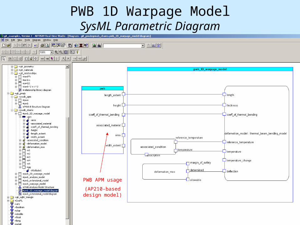
PWB 1D Warpage ModelSysML Parametric Diagram
PWB APM usage
(AP210-baseddesign model)
Page 43
43
Thermal Beam Bending Model (git_lib\git_abbs)SysML Parametric DiagramThis ABB is used for the 1D warpage model of the PWB
relationship reused (a = b - c)
Page 44
44
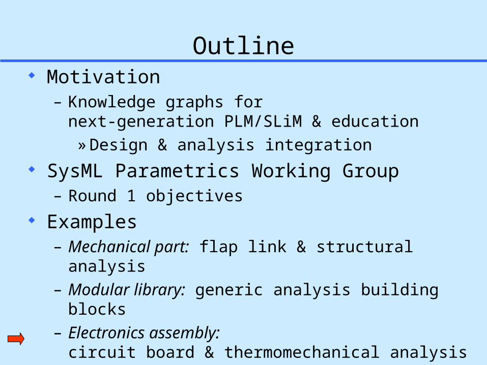
Outline Motivation
– Knowledge graphs for next-generation PLM/SLiM & education
» Design & analysis integration SysML Parametrics Working Group
– Round 1 objectives Examples
– Mechanical part: flap link & structural analysis– Modular library: generic analysis building blocks– Electronics assembly:
circuit board & thermomechanical analysis Results & Summary
Page 45
45
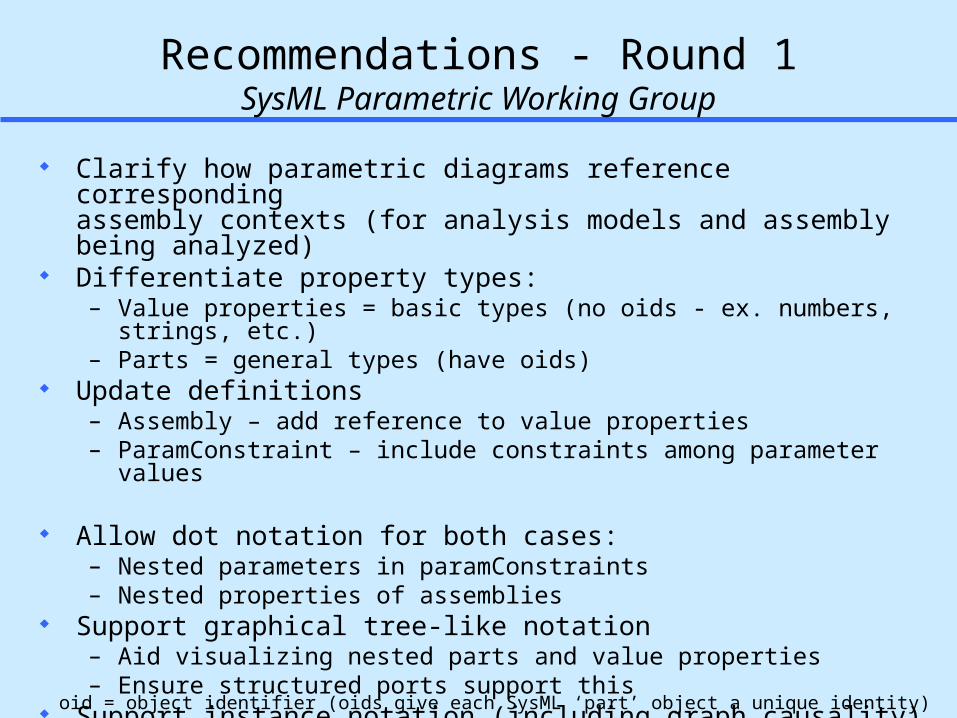
Recommendations - Round 1SysML Parametric Working Group
Clarify how parametric diagrams reference corresponding assembly contexts (for analysis models and assembly being analyzed)
Differentiate property types:– Value properties = basic types (no oids - ex. numbers, strings, etc.)– Parts = general types (have oids)
Update definitions– Assembly – add reference to value properties– ParamConstraint – include constraints among parameter values
Allow dot notation for both cases:– Nested parameters in paramConstraints – Nested properties of assemblies
Support graphical tree-like notation – Aid visualizing nested parts and value properties – Ensure structured ports support this
Support instance notation (including graph causality) Support promoted ports
oid = object identifier (oids give each SysML ‘part’ object a unique identity)
Page 46
46
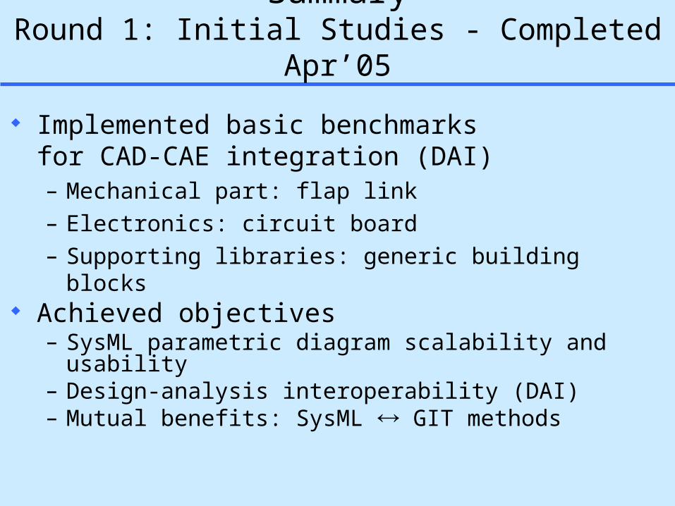
SummaryRound 1: Initial Studies - Completed Apr’05
Implemented basic benchmarks for CAD-CAE integration (DAI)– Mechanical part: flap link– Electronics: circuit board– Supporting libraries: generic building blocks
Achieved objectives– SysML parametric diagram scalability and usability – Design-analysis interoperability (DAI)– Mutual benefits: SysML GIT methods
Page 47
47
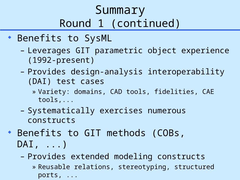
SummaryRound 1 (continued)
Benefits to SysML– Leverages GIT parametric object experience
(1992-present)– Provides design-analysis interoperability (DAI) test cases
» Variety: domains, CAD tools, fidelities, CAE tools,...
– Systematically exercises numerous constructs Benefits to GIT methods (COBs, DAI, ...)
– Provides extended modeling constructs» Reusable relations, stereotyping, structured ports, ...
– Broadens & enhances tool support – Increases modeling effectiveness (via tools)
» Tool-aided graphical view creation» Automated consistency between views
Page 48
48
Next Steps: Round 2 Refine above examples
– Consistency & approach Iterate:
– Propose SysML enhancements– Test with above examples & extended examples– Identify any remaining issues & enhancements
Provide feedback ~May’05 to enhance SysML specification v1.0
Page 49
49
References
www.SysML.org GIT design-analysis interoperability methods,
including constrained objects (COBs):– http://eislab.gatech.edu/pubs/seminars-etc/2005-cpda-dsfw-peak/
Check here for updated versions of this presentation and related material– http://eislab.gatech.edu/pubs/conferences/2005-pde-peak/
Page 50
50
Recommended ReferenceAchieving Fine-Grained CAE-CAE Associativity via
Analyzable Product Model (APM)-based Idealizations
Topic Area: Design-Analysis Interoperability (DAI)
This presentation overviews a simulation template methodology based on the analyzable product model (APM) knowledge representation. APMs combine design information from multiple sources, add idealization knowledge, and bridge semantic gaps to enable advanced CAD-CAE interoperability.
To understand why generalized design-simulation integration is a challenging proposition, we first review concepts like heterogeneous transformations and multi-fidelity idealizations via industrial examples.
Next we describe how an APM is a key component in the multi-representation architecture (MRA) simulation template methodology. In brief, MRA-based templates connect APMs with analysis models in a manner that is reusable, modular, and multi-directional. This approach supports multiple levels of abstraction and enhances physical behavior modeling and knowledge capture for a wide variety of design models, analysis models, and engineering computing environments.
Finally, we walk through several design-analysis scenarios including airframe structural analysis and electronics thermal and deformation analysis. Such examples demonstrate how the MRA supports a diversity of physical behaviors, analysis fidelities, and CAD/CAE methods and tools in a unified manner. This holistic approach leverages rich product models and open standards (e.g., STEP AP210 for electronics and AP233/SysML for systems of systems) and provides a foundation for next-generation design/simulation frameworks.
http://eislab.gatech.edu/pubs/seminars-etc/2005-cpda-dsfw-peak/
Page 52
52
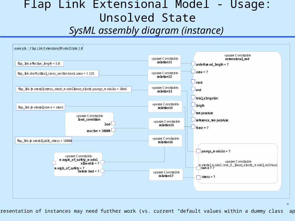
Flap Link Extensional Model - Usage: Unsolved StateSysML assembly diagram (instance)
Caveat: representation of instances may need further work (vs. current “default values within a dummy class” approach)
«paramConstraint»margin_of_safety_model
margin_of_safety = ?allowable = ?
determined = ?margin_of_safety = ?
allowable = ?
determined = ?
«paramConstraint»extensional_rod
area = ?
undeformed_length = ?
start
end
length
temperature
reference_temperature
force = ?
«paramConstraint»material_model : one_D_linear_elastic_model_noShear
name = ?
youngs_modulus = ?
stress = ?
total_elongation
area = ?
undeformed_length = ?
start
end
length
temperature
reference_temperature
force = ?
«paramConstraint»material_model : one_D_linear_elastic_model_noShear
name = ?
youngs_modulus = ?
stress = ?
name = ?
youngs_modulus = ?
stress = ?
total_elongation
«paramConstraint»relation11
«paramConstraint»relation12
«paramConstraint»relation13
«paramConstraint»relation14
«paramConstraint»relation16
«paramConstraint»relation17
«paramConstraint»relation15
«paramConstraint»load_condition
reaction = 10000
load
reaction = 10000
load
flap_link.[material].name = steel
flap_link.[material].yield_stress = 18000
flap_link.effective_length = 5.0
flap_link.shaft.critical_cross_section.basic.area = 1.125
flap_link.[material].stress_strain_model.linear_elastic.youngs_modulus = 30e6
example : Flap Link Extensional Model State 1.0
Page 53
Constrained Object (COB) Basics
Page 54
54
Constrained Object (COB) Modeling LanguagesLexical and Graphical Formulations
StructureLevel(Template)
InstanceLevel
Subsystem-S
Object Relationship Diagram-S
COB StructureDefinition Language
(COS)
I/O Table-S
Constraint Graph-S
Constraint Schematic-S
STEPExpress
Express-G
Lexical Formulations
OWL UMLXML
COB InstanceDefinition Language
(COI)
Constraint Graph-I
Constraint Schematic-I
STEPPart 21
200 lbs
30e6 psi
100 lbs 20.2 in
R101
R101
100 lbs
30e6 psi 200 lbs
20.2 in OWL UML
Lexical Formulations
XML
OWL, XML, and UML formulationsare envisioned extensions
Page 55
55
Triangle
dh
Ab
Triangle
dh
Ab
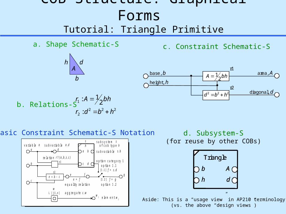
COB Structure: Graphical Forms
Tutorial: Triangle Primitive
v a r i a b l e s u b v a r i a b l es u b s y s t e m
e q u a l i t y r e l a t i o n
r e l a t i o n
s
a b
dc
a
b
d
c
e
a . das
r 1r 1 ( a , b , s . c )
e = f
s u b v a r i a b l e s . b
[ 1 . 2 ]
[ 1 . 1 ]o p t i o n 1 . 1
ff = s . d
o p t i o n 1 . 2 f = g
o p t i o n c a t e g o r y 1
gcbe r 2
h o f c o b t y p e h
wL [ j : 1 , n ]
w ja g g r e g a t e c . w
e l e m e n t w j
Basic Constraint Schematic-S Notation
c. Constraint Schematic-Sa. Shape Schematic-S
2222
1
:2
1:
hbdr
bhAr
b. Relations-S
d. Subsystem-S(for reuse by other COBs)
h
bA
d
base, br1
r2
bhA 21
height, h
222 hbd
area, A
diagonal, d
Aside: This is a “usage view” in AP210 terminology (vs. the above “design views”)
Page 56
56
TriangularPrism
Vh
b
l
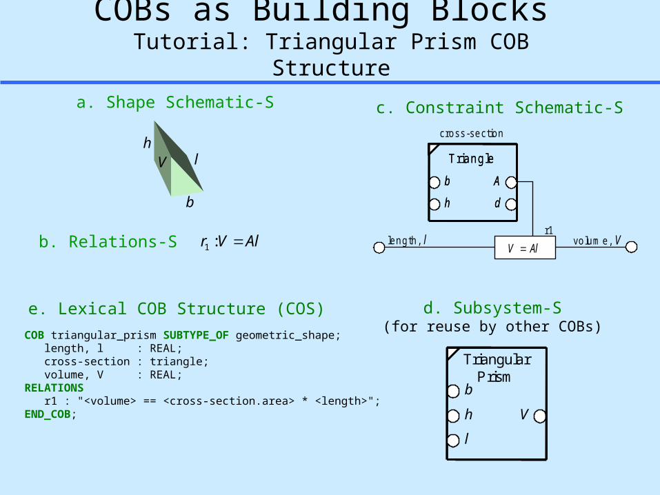
COBs as Building Blocks Tutorial: Triangular Prism COB Structure
c. Constraint Schematic-Sa. Shape Schematic-S
b. Relations-S
d. Subsystem-S(for reuse by other COBs)
T ria n g le
dh
Ab
T ria n g le
dh
Ab
le n g th , l vo lu m e , Vr1
AlV
c ro s s -se c tio nh
b
V l
AlVr :1
e. Lexical COB Structure (COS)COB triangular_prism SUBTYPE_OF geometric_shape; length, l : REAL; cross-section : triangle; volume, V : REAL;RELATIONS r1 : "<volume> == <cross-section.area> * <length>";END_COB;
Page 57
57
200 lbs
30e6 psiResult b = 30e6 psi (output or intermediate variable)
Result c = 200 lbs (result of primary interest)
X
Relation r1 is suspended X r1
100 lbs Input a = 100 lbs
Equality relation is suspended
a
b
c
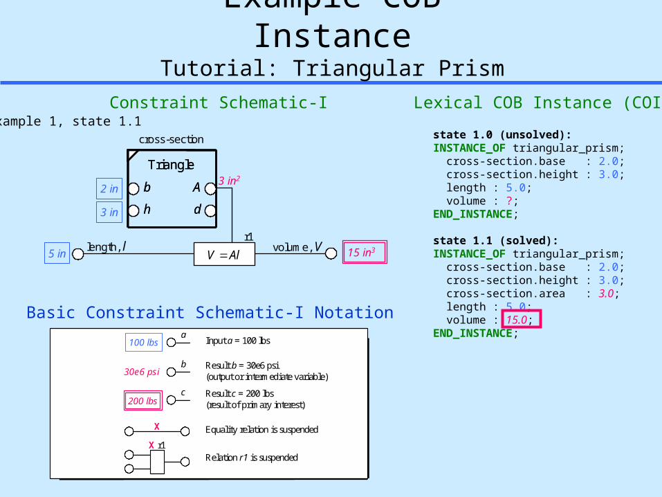
Example COB InstanceTutorial: Triangular Prism
Constraint Schematic-I Lexical COB Instance (COI)
state 1.0 (unsolved):INSTANCE_OF triangular_prism; cross-section.base : 2.0; cross-section.height : 3.0; length : 5.0; volume : ?;END_INSTANCE;
state 1.1 (solved):INSTANCE_OF triangular_prism; cross-section.base : 2.0; cross-section.height : 3.0; cross-section.area : 3.0; length : 5.0; volume : 15.0;END_INSTANCE;
Basic Constraint Schematic-I Notation
example 1, state 1.1
Triangle
dh
Ab
Triangle
dh
Ab
length, l volume, Vr1
AlV
cross-section
3 in22 in
3 in
15 in35 in
Page 58
Other Potential Examples and Challenges
Page 59
59
Analysis Tools
0.4375 in
0.5240 in
0.0000 in
2.440 in
1.267 in
0.307 in
0.5 in
0.310 in
2.088 in
1.770 in
67000 psi
65000 psi
57000 psi
52000 psi
39000 psi
0.067 in/in
0.030 in/in
5960 Ibs
1
10000000 psi
9.17
5.11
9.77
rear spar fitting attach point
BLE7K18
2G7T12U (Detent 0, Fairing Condition 1)
L29 -300
Outboard TE Flap, Support No 2;Inboard Beam, 123L4567
Bulkhead Fitting Joint
Program
Part
Feature
Channel FittingStatic Strength Analysis
Template
1 of 1Dataset
strength model
r1
e
b
h
tb
te
Pu
Ftu
E
r2
r0
a
F tuLT
Fty
F tyLT
epuLT
tw
MSwall
epu
jm
MSepb
MSeps
Channel FittingStatic Strength Analysis
F su
IAS FunctionRef D6-81766
end pad
base
material
wall
analysis context
mode: (ultimate static strength)
condition:
heuristic: overall fitting factor, Jm
bolt
fitting
headradius, r1
hole radius, ro
width, b
eccentricity, ethickness, teheight, h
radius, r2
thickness, tb
hole
thickness, twangled height, a
max allowable ultimate stress,
allowable ultimate long transverse stress,max allowable yield stress,
max allowable long transverse stress,max allowable shear stress,plastic ultimate strain,
plastic ultimate strain long transverse,young modulus of elasticity,
load, Pu
Ftu
Fty
FtyLT
F su
epu
epuLT
E
FtuLT
product structure (channel f itting joint)
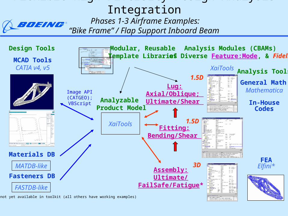
Flexible High Diversity Design-Analysis Integration Phases 1-3 Airframe Examples:
“Bike Frame” / Flap Support Inboard Beam
Analysis Modules (CBAMs) of Diverse Feature:Mode, & Fidelity
Design Tools
Materials DBFEA
Elfini*MATDB-like
Analyzable Product Model
XaiTools
XaiTools
Fitting:Bending/Shear
3D
1.5D
Modular, ReusableTemplate LibrariesMCAD Tools
CATIA v4, v5
Lug:Axial/Oblique; Ultimate/Shear
1.5D
Assembly:Ultimate/
FailSafe/Fatigue** = Item not yet available in toolkit (all others have working examples)
diagonal brace lug joint j = top
0.7500 in
0.35 in
0.7500 in
1.6000 in
2
0.7433
14.686 K
2.40
4.317 K
8.633 K
k = norm
Max. torque brake settingdetent 30, 2=3.5º
7050-T7452, MS 7-214
67 Ksi
L29 -300
Outboard TE Flap, Support No 2;Inboard Beam, 123L4567
Diagonal Brace Lug Joint
Program
Part
Feature
Lug JointAxial Ultimate Strength Model
Template
j = top lugk = normal diameter (1 of 4)
Dataset
material
deformation model
max allowable ultimate stress, FtuL
effective width, W
analysis context
objective
mode (ultimate static strength)
condition
estimated axial ultimate strength
Margin of Safety(> case)
allowableactual
MS
normal diameter, Dnorm
thickness, t
edge margin, e
Plug joint
size,n
lugs
lugj hole
diameters
product structure (lug joint)
r1
nP join tlug
L [ j:1,n ]
Plug
L [ k]Dk
oversize diameter, DoverD
PaxuWe
t
Ftuax
Kaxu
Lug Axial UltimateStrength Model
BDM 6630
Fasteners DB
FASTDB-like
General Math Mathematica
In-HouseCodes
Image API(CATGEO);
VBScript
Page 60
60
Fitting Analysis Template Applied to “Bike Frame” Bulkhead CBAM constraint schematic - instance view
0.4375 in
0.5240 in
0.0000 in
2.440 in
1.267 in
0.307 in
0.5 in
0.310 in
2.088 in
1.770 in
67000 psi
65000 psi
57000 psi
52000 psi
39000 psi
0.067 in/in
0.030 in/in
5960 Ibs
1
10000000 psi
9.17
5.11
9.77
bulkhead fitting attach point
LE7K18
2G7T12U (Detent 0, Fairing Condition 1)
L29 -300
Outboard TE Flap, Support No 2;Inboard Beam, 123L4567
Bulkhead Fitting Joint
Program
Part
Feature
Channel FittingStatic Strength Analysis
Template
1 of 1Dataset
strength model
r1
e
b
h
tb
te
Pu
Ftu
E
r2
r0
a
FtuLT
Fty
FtyLT
epuLT
tw
MSwall
epu
jm
MSepb
MSeps
Channel FittingStatic Strength Analysis
Fsu
IAS FunctionRef DM 6-81766
end pad
base
material
wall
analysis context
mode: (ultimate static strength)
condition:
heuristic: overall fitting factor, Jm
bolt
fitting
headradius, r1
hole radius, ro
width, b
eccentricity, ethickness, teheight, h
radius, r2
thickness, tb
hole
thickness, twangled height, a
max allowable ultimate stress,
allowable ultimate long transverse stress,max allowable yield stress,
max allowable long transverse stress,max allowable shear stress,plastic ultimate strain,
plastic ultimate strain long transverse,young modulus of elasticity,
load, Pu
Ftu
Fty
FtyLT
Fsu
epu
epuLT
E
FtuLT
product structure (channel fitting joint)
e
setr
Pf02
21
e
behtPCf
),,( 13 hbrfK
18 associativity relations
Page 61
61
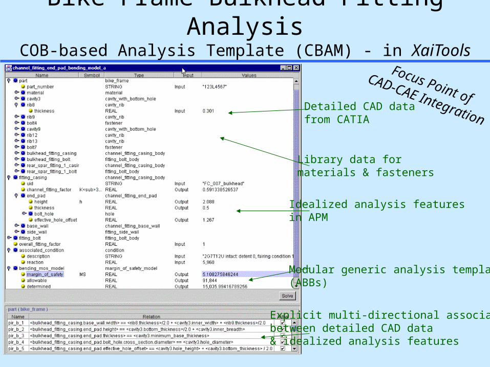
Bike Frame Bulkhead Fitting AnalysisCOB-based Analysis Template (CBAM) - in XaiTools
Detailed CAD datafrom CATIA
Idealized analysis features in APM
Explicit multi-directional associativity between detailed CAD data & idealized analysis features
Modular generic analysis templates(ABBs)
Library data for materials & fasteners
Focus Point ofCAD-CAE Integration
Page 62
62
diagonal brace lug joint j = top
0.7500 in
0.35 in
0.7500 in
1.6000 in
2
0.7433
14.686 K
2.40
4.317 K
8.633 K
k = norm
Max. torque brake settingdetent 30, 2=3.5º
7050-T7452, MS 7-214
67 Ksi
L29 -300
Outboard TE Flap, Support No 2;Inboard Beam, 123L4567
Diagonal Brace Lug Joint
Program
Part
Feature
Lug JointAxial Ultimate Strength Model
Template
j = top lugk = normal diameter (1 of 4)
Dataset
material
deformation model
max allowable ultimate stress, FtuL
effective width, W
analysis context
objective
mode (ultimate static strength)
condition
estimated axial ultimate strength
Margin of Safety(> case)
allowableactual
MS
normal diameter, Dnorm
thickness, t
edge margin, e
Plug joint
size,n
lugs
lugj hole
diameters
product structure (lug joint)
r1
nP jointlug
L [ j:1,n ]
Plug
L [ k]Dk
oversize diameter, DoverD
PaxuWe
t
Ftuax
Kaxu
Lug Axial UltimateStrength Model
DM 6630
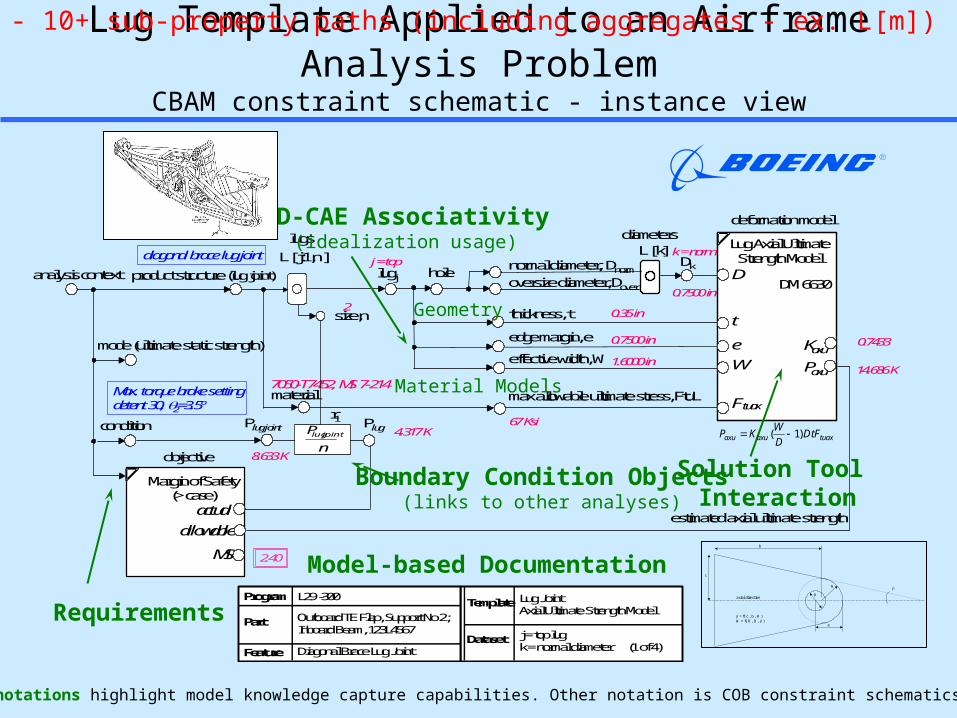
Lug Template Applied to an Airframe Analysis ProblemCBAM constraint schematic - instance view
Solution Tool Interaction
Boundary Condition Objects(links to other analyses)
CAD-CAE Associativity (idealization usage)
Material Models
Model-based Documentation
Geometry
P K WD
DtFaxu axu tuax ( )1
Requirements
Legend: Annotations highlight model knowledge capture capabilities. Other notation is COB constraint schematics notation.
R
c
b
= f( c , b , R )W = f( R , D , )
axial direction
e
D
- 10+ sub-property paths (including aggregates - ex. L[m])
Page 63
63
Target Situation: Design Driven by AnalysisSimulation-based design (SBD)
Idealized Analysis Features (to scale in CATIA v5)
Idealized bulkhead attach point fitting
Design Model (in CATIA v5)
Idealized rear spar attach point fitting
Idealized diagonal brace lug joint
R
c
b
= f( c , b , R )W = f( R , D , )
axial direction
e
D
Page 64
64
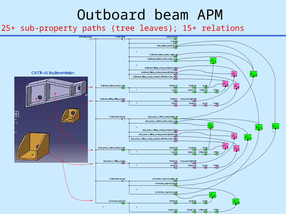
Outboard beam APM
263r
24rbulkhead_attach_point_cavity
outboard_beam Parameters
material
inter_attach_point_length
bulkhead_attach_point_cavity_angle
bulkhead_fitting_casing_endpad_height
bulkhead_fitting_casing_endpad_effective_hole_offset
bulkhead_fitting_casing_basewall_thickness
Sketch.13
end_pad_height.20
Angle.12
Sketch.15
Sketch.2
Hole.3
Sketch.1
Body.2
Angle
Offset.54
t_b.43
Offset
Offset
11r
33r
10r
bulkhead_fitting_fitting_casing
……
…
…
74rrear_spar_1_attach_point_cavity
rear_spar_1_attach_point_cavity_angle
rear_spar_1_fitting_casing_endpad_height
rear_spar_1_fitting_casing_endpad_effective_hole_offset
rear_spar_1_fitting_casing_basewall_thickness
Sketch.63
end_pad_height.70
Angle.62
Sketch.65
Sketch.52
Hole.53
Sketch.51
Body.52
Angle
Offset.104
t_b.93
Offset
Offset
61r
83r
60r
rear_spar_1_fitting_casing
……
…
Parameters (cont.)
…
bulkhead_attach_point_ origin_x0
rear_spar_1_attach_point_origin_x0
connector_segment
connector_segment_length
Sketch.163 Sketch.165 Offset.204 Offset
184r
……
Parameters (cont.) connector_ segment_origin_x0
connector_ segment_angle
Sketch.63 Angle.62 Angle
183r
274r
210r
part_number
212r
…
CATIA v5 Implementation
25+ sub-property paths (tree leaves); 15+ relations