(12) United States Patent Miller et al. US008885291B2 US 8,885,291 B2 Nov. 11, 2014 (10) Patent No.: (45) Date of Patent: (54) (71) (72) (73) (*) (21) (22) (65) (60) (51) (52) (58) RECIRCULATION FILTER FORAN ELECTRONIC ENCLOSURE Applicant: Donaldson Company, Inc., Minneapolis, MN (US) Inventors: Stanley B. Miller, Eden Prairie, MN (US); Allen N. Nicklay, Eden Prairie, MN (US); Christopher J. Fischer, Minneapolis, MN (US) Assignee: Donaldson Company, Inc., Minneapolis, MN (US) Notice: Subject to any disclaimer, the term of this patent is extended or adjusted under 35 U.S.C. 154(b) by 0 days. Appl. No.: 13/831,458 Filed: Mar 14, 2013 Prior Publication Data US 2014/OO43711 A1 Feb. 13, 2014 Related U.S. Application Data Provisional application No. 61/681,618, filed on Aug. 10, 2012. Int. C. GIIB 33/14 (2006.01) BOID 46/00 (2006.01) BOID 46/24 (2006.01) U.S. C. CPC .......... GI IB33/146 (2013.01); B01D 46/0032 (2013.01); B0ID 2279/45 (2013.01); B01D 46/24 (2013.01) USPC ....................................................... 360/97.16 Field of Classification Search USPC .......... 360/97.16, 97.14, 97.13, 97.15, 97.19, 360/99.15, 99.23, 99.13, 99.22 See application file for complete search history. 208 202 (56) References Cited U.S. PATENT DOCUMENTS 4.418,369 A 11/1983 Appleduist et al. 4,488,193 A 12/1984 Davis et al. 4,581,668 A 4/1986 Campbell 4,594,626 A 6/1986 Frangesh 4,725,904 A 2f1988 Dalziel 4,809,102 A 2f1989 Hatchett et al. 4,857,087 A 8, 1989 Bolton et al. 5,025,337 A 6, 1991 Brooks 5,030,260 A 7, 1991 Becket al. 5,406,431 A 4/1995 Beecroft 5,417,743 A 5, 1995 Dauber 5,538,545 A 7/1996 Dauber et al. (Continued) FOREIGN PATENT DOCUMENTS EP O123130 10, 1984 EP O263932 4f1988 (Continued) OTHER PUBLICATIONS International Search Report and Written Opinion for PCT/US2013/ 054446, mailed Dec. 11, 2013 (17 pages). Primary Examiner — Allen T Cao (74) Attorney, Agent, or Firm — Pauly, DeVries Smith & Deffner, LLC (57) ABSTRACT A filter assembly for use in an electronic enclosure is pro vided. The filter assembly includes a highly permeable scrim that defines an elongate enclosure with an inlet at a first end and a closed second end, wherein an electrostatic filtration media is disposed within the elongate enclosure. 20 Claims, 16 Drawing Sheets SEAL
USPC ....................................................... 360/97.16 Field of Classification Search USPC .......... 360/97.16, 97.14, 97.13, 97.15, 97.19,
360/99.15, 99.23, 99.13, 99.22 See application file for complete search history.
208
202
(56) References Cited
U.S. PATENT DOCUMENTS
4.418,369 A 11/1983 Appleduist et al. 4,488,193 A 12/1984 Davis et al. 4,581,668 A 4/1986 Campbell 4,594,626 A 6/1986 Frangesh 4,725,904 A 2f1988 Dalziel 4,809,102 A 2f1989 Hatchett et al. 4,857,087 A 8, 1989 Bolton et al. 5,025,337 A 6, 1991 Brooks 5,030,260 A 7, 1991 Becket al. 5,406,431 A 4/1995 Beecroft 5,417,743 A 5, 1995 Dauber 5,538,545 A 7/1996 Dauber et al.
(Continued)
FOREIGN PATENT DOCUMENTS
EP O123130 10, 1984 EP O263932 4f1988
(Continued)
OTHER PUBLICATIONS
International Search Report and Written Opinion for PCT/US2013/ 054446, mailed Dec. 11, 2013 (17 pages).
Primary Examiner — Allen T Cao (74) Attorney, Agent, or Firm — Pauly, DeVries Smith & Deffner, LLC
(57) ABSTRACT
A filter assembly for use in an electronic enclosure is pro vided. The filter assembly includes a highly permeable scrim that defines an elongate enclosure with an inlet at a first end and a closed second end, wherein an electrostatic filtration media is disposed within the elongate enclosure.
Becket al. Dauber et al. Bruner et al. Bordes Boutaghou Brooks Becket al. BoigenZahn et al. BoigenZahn et al. Schneider et al. Schneider et al. Voights Toney et al. AZarian et al. BoigenZahn et al. Gidumal ............. Dauber ........................... 96.134 Turner Voights Bruner et al. Little Johnson et al. Isogawa et al. Albrecht et al. Yoo Logan Rutledge et al. Tuma et al. Dauber et al. McMaster et al. Gorton et al. Voights et al. ...... Ball et al. Turner et al. ............... 360/97.16 Little et al. Garikipati et al. Yu et al. Avina Han et al. Johnson .............. Boulay et al. Albrecht et al. Han et al. Oh et al. Dauber et al. Avina Chan et al. .......... Miller, III
EP EP EP GB GB GB WO WO WO WO WO WO WO WO WO WO WO WO WO WO WO WO WO WO WO WO WO WO WO
Kalayci et al. Mohseni et al. Bishop et al. Brown .......... Boulinois et al. Isogawa et al. Johnson et al. Logan Tuma et al. Voights et al. Gogins et al. Johnson Olszewski Boulay et al. Olszewski Dauber et al. Brown ..........
U.S. Patent Nov. 11, 2014 Sheet 1 of 16 US 8,885,291 B2
U.S. Patent Nov. 11, 2014 Sheet 2 of 16 US 8,885,291 B2
200
? 204
FIG. 2 208 -20 3'
204
212 2O6
2OO
FIG. 3 ?
208
FIG. 4
U.S. Patent Nov. 11, 2014 Sheet 3 of 16 US 8,885,291 B2
208
U.S. Patent Nov. 11, 2014 Sheet 4 of 16 US 8,885,291 B2
v- 200
FIG. 6
U.S. Patent Nov. 11, 2014 Sheet 5 of 16 US 8,885,291 B2
FIG. 7A
3O8
3O2 3O6 3O6
3O4. D. FIG. 7C
U.S. Patent Nov. 11, 2014 Sheet 6 of 16 US 8,885,291 B2
4.08
D
FIG. 8
U.S. Patent Nov. 11, 2014 Sheet 7 of 16 US 8,885,291 B2
U.S. Patent Nov. 11, 2014 Sheet 8 of 16 US 8,885,291 B2
-10 1120
1122
U.S. Patent Nov. 11, 2014 Sheet 9 of 16 US 8,885,291 B2
US 8,885,291 B2 Sheet 10 of 16 Nov. 11, 2014 U.S. Patent
FIG. 11E
s 33 33
ES s
s s
33
s s s
s s s s s s
FIG 11 F
U.S. Patent Nov. 11, 2014 Sheet 11 of 16 US 8,885,291 B2
FIG. 11
U.S. Patent Nov. 11, 2014 Sheet 12 of 16 US 8,885,291 B2
1110
Between Horn and Nest
FIG. 11J
U.S. Patent Nov. 11, 2014 Sheet 13 of 16 US 8,885,291 B2
-10 1222
FIG. 12A
1214
1214
FIG. 12B
U.S. Patent Nov. 11, 2014 Sheet 14 of 16 US 8,885,291 B2
|-
U.S. Patent Nov. 11, 2014 Sheet 15 of 16 US 8,885,291 B2
1. 1200
FIG. 12G
U.S. Patent Nov. 11, 2014 Sheet 16 of 16 US 8,885,291 B2
Weld Layers Together
Sandwich First Filter Material Between the Horn and the Nest
Lower Horn into Recess
Place Second Filter Material on Top of the Horn
Weld First Filter Material to Second
Filter Material
FIG. 12
US 8,885,291 B2 1.
RECIRCULATION FILTER FOR AN ELECTRONIC ENCLOSURE
FIELD OF THE INVENTION
The present invention is directed to filters for use in elec tronic enclosures. In particular, the invention is directed to filters for removing contaminants circulating within the inte rior of an electronic enclosure.
BACKGROUND
Contaminants within an electronic enclosure. Such as a hard disk drive enclosure, can reduce the efficiency and lon gevity of the components within the enclosure. Contaminants can include chemicals and particulates, and can enter the hard drive enclosure from external sources, or be generated within the enclosure during manufacture or use. The contaminants can gradually damage the drive, resulting in deterioration of drive performance and even complete failure of the drive. Consequently, data storage systems such as hard disk drives typically include one or more filters capable of removing or preventing entry of particulate and/or chemical contaminants in the air within the disk drive enclosure. One type of such filter is a recirculation filter, which is generally placed such that it can filter out contaminants from the path of airflow caused by rotation of one or more disks within the disk drive. Although existing recirculation filters can remove many con taminants, a need exists for improved performance at remov ing certain contaminants, in particular, large particulate con taminants.
SUMMARY OF THE INVENTION
The present application is directed, in part, to filter assem blies for use in an electronic enclosure. The filter assemblies are designed to remove particulate contaminants circulating within the electronic enclosure. In particular, the filter assem blies are constructed and arranged so as to effectively reduce the particulate contaminant levels by capturing the particles and preventing their release back into the electronic enclo sure. Typically the filter assemblies are constructed with a media geometry that aids in the capture of particles, and which avoids reflection of particles out of the filter assem blies.
The filter assemblies further include, in various embodi ments, media configurations that are further designed to pro mote the capture of particulate contaminants. These media configurations include, for example, constructions with an electrostatic media overlaying all or part of a scrim material on the interior of the filter assembly. Without intending to be bound by a specific mechanism of operation, it is believed that the electrostatic helps prevent particles from striking the media and then bouncing off (often referred to as reflection), which can otherwise occur with exposed scrimmaterials. The electrostatic may also further help in capturing the particles to prevent their continued circulation through the electronic enclosure.
In an example embodiment, the filter assembly includes a media structure that includes an open front end, a closed rear end, and an internal recess between the open front end and closed rear end. Permeable filter media forms at least a por tion of the recess. The recess is typically relatively deep, in some cases as deep or deeper than the width of the filter assembly. Thus, the recess can be conical or column shaped (for example) in some embodiments. This recirculation filter structure with an internal recess promotes the capture and
10
15
25
30
35
40
45
50
55
60
65
2 retention of particulate contaminants by having a large open front Surface area while having an even larger interior Surface area comprising filter media. The interior media Surface is generally angled relative to the air flow direction so that particles hit the media at an acute angle Such that they can either be retained by the media at the point of initial contact or slowed down sufficiently to be retained deeper inside the filter assembly.
In some implementations at least 50 percent of the surface area of the internal recess has an angle to the opening that is less than or equal to 45 degrees. At least 75 percent of the Surface area of the internal recess has an angle to the opening that is less than or equal to 45 degrees in Some example implementations. Optionally at least 50 percent of the surface area of the internal recess has an angle to the opening that is less than or equal to 30 degrees. In some example embodi ments at least 75 percent of the surface area of the internal recess has an angle to the opening that is less than or equal to 30 degrees.
In certain implementations the internal recess of the filter assembly has a ratio of maximum depth to maximum diam eter of the open front face of at least 1.0, but this maximum depth to maximum diameterratio can vary, and is often higher than 1.0, such as higher than 1.25, 1.5, 1.75; or 2.0, for example. The internal recess of the filter assembly can have an internal Surface area that is at least 2 times the area at the open front face, in other implementations at least 3 times the area at the open front face, and in other implementations at least 4 times the area at the open front face, at least 4 times the area of the open face in some implementations, or at least 5 or 6 times the area at the open front face in certain embodiments.
In some embodiments, the permeable scrim material com prises woven or non-woven material. Such as polypropylene fibers. The scrim material can have, for example, a perme ability of between about 100 ft./min. at 0.5 inches of water and about 800 ft/min. at 0.5 inches of water in some embodi ments. In certain embodiments the scrim material has a per meability of between about 250 ft./min. at 0.5 inches of water and about 600 ft/min. at 0.5 inches of water. The scrim material has a permeability of between about 300 ft/min. at 0.5 inches of water and about 500 ft/min. at 0.5 inches of water in some example implementations. It will be under stood that suitable scrim material can have, for example, a permeability of more than 100 ft./min. at 0.5 inches of water; more than 250 ft./min. at 0.5 inches of water, or more than 300 ft/min. at 0.5 inches of water. Suitable scrim material can have, for example, a permeability of less than about 800 ft/min. at 0.5 inches of water in some embodiments; less than 600 ft/min. at 0.5 inches of water in some embodiments; or less than 500 ft/min. at 0.5 inches of water in some embodi mentS.
The electrostatic material can contain various fibers, and is optionally a mixed fiber media comprising polypropylene and acrylic fibers. The electrostatic material has, for example, a permeability of between about 250 ft./min. at 0.5 inches of water and about 750 ft./min. at 0.5 inches of water. The electrostatic material can have a filtering efficiency of about 20% to about 99.99% for 20 to 30 micron particulate con taminants in Some embodiments. Suitable electrostatic can, for example, have a filtering efficiency of greater than 20% for 20 to 30 micron particulate contaminants; greater than 40% for 20 to 30 micron particulate contaminants; or greater than 60% for 20 to 30 micron particulate contaminants. The elec trostatic material can have in some example implementations a filtering efficiency of less than 99.99% for 20 to 30 micron
US 8,885,291 B2 3
particulate contaminants; less than 80% for 20 to 30 micron particulate contaminants; or less than 60% for 20 to 30 micron particulate contaminants. The above summary of the present invention is not
intended to describe each discussed embodiment of the present invention. This is the purpose of the figures and the detailed description that follows.
BRIEF DESCRIPTION OF THE DRAWINGS
The invention will be more fully explained with reference to the following drawings.
FIG. 1 is a simplified perspective view of a disk drive assembly, showing the top of the disk drive assembly removed.
FIG. 2 is a perspective view of a filter assembly constructed and arranged in accordance with an implementation of the invention.
FIG. 3 is a side elevation view of a filter assembly con structed and arranged in accordance with the implementation of the invention shown in FIG. 2.
FIG. 4 is a front elevational view of a filter assembly constructed and arranged in accordance with the implemen tation of the invention shown in FIG. 2.
FIG. 5A is a cross-sectional view of the filter assembly of FIG. 3 taken along line 3-3'.
FIG. 5B is a detail of a portion of the filter assembly shown in cross section in FIG. 5A, showing the media layers.
FIG. 6 is a partial top plan view of disk drive assembly containing a filter assembly constructed and arranged in accordance with an example implementation of the present invention.
FIGS. 7A-7D are schematic depictions showing a method of making a filter assembly as described herein.
FIG. 8 is a cross sectional view of a filter assembly made in accordance with an implementation of the invention, the filter assembly having an inclined opening.
FIG. 9 is a perspective view of a filter assembly made in accordance with an implementation of the invention, the filter assembly having a plurality of filtration recesses.
FIG. 10 is a cross sectional view of the filter assembly of FIG.9 taken along lines 9-9'
FIGS. 11A-11 I are schematic depictions showing a method of making a filter assembly as described herein.
FIG. 11J is chart depicting a method of making a filter assembly as described herein
FIGS. 12A-12G are schematic depictions showing a method of making a filter assembly as described herein.
FIG. 12H is chart depicting a method of making a filter assembly as described herein
While principles of the invention are amenable to various modifications and alternative forms, specifics thereof have been shown by way of example in the drawings and will be described in detail. It should be understood, however, that the intention is not to limit the invention to the particular embodi ments described. On the contrary, the intention is to cover all modifications, equivalents, and alternatives falling within the spirit and scope of the disclosure and claims.
DETAILED DESCRIPTION
Various filtering systems are known that are used to reduce or remove contaminants from disk drive assemblies, as well as other electronic enclosures. In particular, recirculation fil ters are often used to reduce or remove particulate and/or chemical contaminants that have entered a disk drive enclo Sure or been generated during use of the disk drive. A typical
10
15
25
30
35
40
45
50
55
60
65
4 recirculation filter includes a filter element that is positioned in the path of air currents induced by disk rotation such that contaminants present in the air current are subject to filtration.
However, not all particles that come into contact with the filter are successfully captured. The face velocity of many available filter assemblies is very high, which can increase particle momentum. The high momentum can result in par ticulate contaminants “reflecting or “bouncing off the filter surface, rather than being entrapped by the filter. This phe nomenon can be referred to as “particle bounce.” Exposed scrim material, which makes up the Surface of many existing recirculation filters, can be a particular problem because par ticles bounce off the scrim fibers at relatively high rates. Thus, a need exists for an improved recirculation filter that can capture even particulate contaminants having relatively high momentum.
A filter assembly for use in an electronic enclosure is described herein to provide improved particulate contami nant removal. In an example embodiment, the filter assembly includes a media structure having an open front face, a closed rear face, and an internal recess between the open front face and closed rear face. A permeable scrim material can form at least a portion of the media structure. An electrostatic mate rial is disposed within the internal recess of the filter assem bly, the electrostatic material at least partially covering the permeable scrim. In an example embodiment the electrostatic material will overlay all or most of the permeable scrim. In Some embodiments the electrostatic material and scrim are combined together before production of the filter assembly (such as, for example, by lamination, heat bonding, or light calendaring) and Subsequently formed into a media structure that creates at least a portion of the filter assembly.
In certain implementations the internal recess of the filter assembly has a ratio of maximum depth to maximum diam eter of the open front face of at least 1.0, but this maximum depth to maximum diameterratio can vary, and is often higher than 1.0, such as 1.25, 1.5, 1.75; or 2.0, for example. The internal recess of the filter assembly can have an internal Surface area that is at least 2 times the area at the open front face, in other implementations at least 3 times the area at the open front face, and in other implementations at least 4 times the area at the open front face, or at least 5 or 6 times the area at the open front face.
In some embodiments, the permeable scrim material com prises woven or non-woven material. Such as polypropylene fibers. The scrim material can have, for example, a perme ability of between about 100 ft./min. at 0.5 inches of water and about 800 ft/min. at 0.5 inches of water in some embodi ments. In some embodiments the scrim material has a perme ability of about 250 ft./min. at 0.5 inches of water and about 600 ft./min. at 0.5 inches of water. In yet other implementa tions the scrim material has a permeability of about 300 ft/min. at 0.5 inches of water and about 500 ft/min at 0.5 inches of water. It will be understood that suitable scrim material can have, for example, a permeability of more than 100 ft./min. at 0.5 inches of water; more than 250 ft./min. at 0.5 inches of water, or more than 300 ft/min. at 0.5 inches of water. Suitable scrim material can have, for example, a per meability of less than about 800 ft./min. at 0.5 inches of water in some embodiments; less than 600 ft/min. at 0.5 inches of water in some embodiments; or less than 500 ft./min. at 0.5 inches of water in some embodiments. The electrostatic material can contain various fibers, and is
optionally a mixed fiber media comprising polypropylene and acrylic fibers. The electrostatic material has, for example, a permeability of between about 250 ft./min. at 0.5 inches of water and about 750 ft./min. at 0.5 inches of water. The
US 8,885,291 B2 5
electrostatic can have a filtering efficiency of about 20% to about 99.99% for 20 to 30 micron particulate contaminants in Some embodiments. Suitable electrostatic can, for example, have a filtering efficiency of greater than 20% for 20 to 30 micron particulate contaminants; greater than 40% for 20 to 30 micron particulate contaminants; or greater than 60% for 20 to 30 micron particulate contaminants. The electrostatic can have in Some example implementations a filtering effi ciency of less than 99.99% for 20 to 30 micron particulate contaminants; less than 80% for 20 to 30 micron particulate contaminants; or less than 60% for 20 to 30 micron particulate contaminants. Now, in reference to the drawings, FIG. 1 is a simplified
perspective representation of a disk drive 100. The disk drive 100 includes body 102 that forms an enclosure 104. In an example embodiment, one or more rotatable magnetic disks 106 are positioned within the enclosure 104. The rotation of the drive is shown by arrows (although opposite rotation is alternatively possible). Other disk drive components, such as a read-write head and wiring can be incorporated into an armature 108. An example embodiment of a filter assembly 200 is shown
in FIGS. 2, 3 and 4. As shown in FIG. 2, the filter assembly comprises an open front end 202, and a closed rear end 204. The filter assembly 200 includes an elongate media structure 206 between the front end 202 and rear end 204, the elongate media structure 206 being primarily made of filter media, Such as in an example embodiment, a scrim on one side with an electrostatic material on the other side. Preferably the electrostatic media is located on the interior side of the elon gate media structure 206. Sidewalls forming the elongate media structure extend from the open front end 202 to the closed rear end 204. In the implementation shown, the elon gate media structure 206 is secured to a frame 208. The frame 208 can be, for example, a metal or plastic support that secures the media structure 206 and may aid in installation into an electronic enclosure.
This example filter assembly 200 is also shown in FIG. 3, in side elevational view, and in FIG. 4 in front view (taken from the front end 202). Measurement of the diameter"D' of the filter assembly 200 is taken along the open interior of the filter assembly 200 at the front end 202. The opening can be generally circular as shown in FIG. 2. In the alternative, the opening can be oval shaped, otherwise non-circular, and rect angular or otherwise the approximate shape of a polygon, for example. In many embodiments, however, the opening will be circular, semi-circular, ovular, semi-ovular, or otherwise have a generally rounded front opening. This generally rounded front opening allows for ease of manufacture of the filter assembly 200.
In FIG.4, two diameters are shown: D, and D, D, refers to the longest diameter across the open front end 202, and D, refers to a diameter at the open front end 202 that is perpen dicular to D. Diameter of non-circular openings can be mea Sured by taking an average diameter (Such as by averaging the D, and D, diameters), or by measuring a maximum diameter, such as D. In general, at least one of D, and D, is between about 0.25 and about 1 inches. Generally the length “L”. shown in FIG. 2, of the filter assembly 200 is greater than the diameter of the filter assembly 200. Specifically, the length L is typically longer than the longer of D, and D. In some implementations length L is longer than the average of D, and D. In one embodiment, the length “L” of the filter assembly 200 can be at least 1.5, 2, or 3 times the longer of the diameters D, and D, of the filter assembly. The length L can be, for example, between about 0.25 and about 2 inches.
10
15
25
30
35
40
45
50
55
60
65
6 The open front end 202 is generally positioned upstream
from the closed rear end 204 with respect to airflow within the electronic enclosure. The elongate shape of the filter assem bly 200, in particular the elongate media structure 206, increases the surface area of filtration media to which the airflow is exposed, thereby increasing the amount of particles that are captured by the filter assembly 200 during filtration, as well as entrapping particles with higher mass or momen tum. Furthermore, the construction of the filter assembly, with a large front opening, and an even larger media Surface area in the elongate media structure 206, reduces pressure restriction of the filter assembly 200.
In an example embodiment, the filter assembly 200 has a Substantially cylindrical configuration. As used herein, the term “substantially cylindrical means that the front end 202 and rear end 204 of the filter assembly are substantially cir cular and the sidewalls 212 (FIG.3) of the filter assembly 200 are parallel or substantially parallel. In another embodiment, the filter assembly 200 has a substantially conical or parabolic configuration. As used herein, the term 'substantially coni cal or “substantially parabolic’ means that the open front end 202 converges towards the closed rear 204 end of the filter assembly 200. Other filter assembly configurations are also possible, in particular other elongate configurations having an ovoid, square, rectangular or other cross-sectional shape either with or without converging sidewalls, and would fall within the scope of the invention.
While not wishing to be bound by theory, it is believed that the use of an open filtration construction with large media Surface area reduces Surface velocity of the particulate con taminants and can thereby increase particle capture. In an example embodiment, the filtration media has a 20 micronto 30 micron filtering efficiency of about 20% to about 99.99%. The permeability of the filtration media is generally between about 250 ft/min. at 0.5 inches of water and about 750 ft/min. at 0.5 inches of water. The basis weight is generally between about 45gm/m and about 165gm/m.
FIG. 5A shows a cross section of the filter assembly 200 of FIGS. 2 to 4. FIG. 5A shows the angle alphabetween the side wall 212 and a line 214 perpendicular to the front end 202 of the filter assembly 200, corresponding to the path of a particle flowing perpendicular to the front end 202 of the filter assem bly. This angle alpha is typically less than 45 degrees over the majority of the sidewall forming the elongate member 206, and alternatively less than 30 degrees or less than 15 degrees over the majority of the media. FIG. 5B shows a simplified enlarged view of a cross section of the filter assembly, show ing an electrostatic layer 220 and a Support layer 222 (Such as a scrim layer). The line 214 at angle alpha is also shown, depicting the relatively acute angle (e.g. preferably less than 45 degrees) at which particles that are travelling perpendicu lar to the opening will strike the media. In the alternative, the media forming the filter assembly 200 can be formed of a single layer, or more than two layers. Also, in certain embodi ments a portion of the media is single layer, and a portion of the media has more than one layer.
In one embodiment, the filtration media forming the elon gate portion 206 includes electrostatic fibers. The term “elec trostatic fibers, as used herein, refers to fibers that contain an electric charge. One advantage of including electrostatic fibers in the filter assembly 200 is that the filter is not only able to mechanically trap contaminants, but is also able to exert an electrostatic force on contaminants that contain electric charges, thereby increasing the amount of contaminants that are removed from the airstream. The electrostatic media can be triboelectric media, electret media, or any other media that can be charged, or that depends on charging as the main
US 8,885,291 B2 7
mechanism for particle removal. In example embodiments, the electrostatic media include triboelectric fibers. Triboelec tric fibers are known and can be formed, for example, using a mixture of (1) polyolefin fibers such as polyethylene, polypropylene or ethylene and propylene copolymers, with (2) fibers of another polymer, for example, fibers containing hydrocarbon functions Substituted by halogenatoms, such as chlorine or polyacrylonitrile fibers. In general, the polyolefin fibers and the other polymer fibers are included in the elec trostatic media at a weight ratio between about 60:40 or about 20:80 or about 30:70.
FIG. 6 shows a filter assembly 200 installed within an electronic enclosure 100 (only a corner of the enclosure 100 is depicted). The filter assembly 200 is oriented so that the open frontend 202 is directed toward the air stream generated by the rotating disk 106 (depicted directionally by arrows). In the embodiment shown, a baffle 114 is present to aid in the direction of air into the open front end 202 of the filter assem bly 200. The filter assembly 200 can be placed within the electronic enclosure such that the baffle 114 directs air into and through the open front end 202. In certain implementa tions the baffle 114, along with any mounting elements (such as a frame 208 shown in FIG. 2) or other portions of the housing form a channel that directs air into the open frontend 202. In other implementations the filter assembly 200 is posi tioned in a flowing air stream without a channel directing air into it, or only an open sided channel that only partially directs air into the filter assembly 200. One method for making a filter assembly as described
herein is shown schematically in FIG. 7A to 7D. In this method, a sheet of scrim material 302 having a length “L” and a width “W' is provided (FIG. 7A). The scrim material 302 is rolled along an axis substantially parallel to the length L., of the scrim to form a cylindrical or conical article 306 (FIG.7B). The scrim302 is sealed along the length L. of the article, for example, using an adhesive or by welding. An end 304 of the article is then sealed to form a closed article that defines a chamber having a length “L” (FIG.7C). The oppo site end 302 is then adhered to a frame 308, for example, using an adhesive, or by welding (FIG. 7D) and a filtration media, for example, an electrostatic filtration media is introduced into the interior of the elongate member formed by the pro CCSS,
FIG. 8 is a cross sectional view of a filter assembly 400 made in accordance with an alternative implementation of the invention, the filter assembly having an inclined opening 402 secured to a frame 408. Media is configured in an elongate member 406. The filter assembly 400 has a length “L” mea sured from the middle of the opening, and diameter “D’. The overall configuration and performance is similar to that of assembly 200 discussed above, only the open end 402 and frame 408 are angled relative to the elongate media member 406. Also, the filter assembly 400 has sidewalls 410 and 412 of different lengths from one another.
FIG.9 is a perspective view of a filter assembly 500 made in accordance with an implementation of the invention, the filter assembly 500 having a plurality of filtration recesses 520. FIG. 10 is a cross sectional view of the filter assembly of FIG.9 taken along lines 9-9', showing the filter assembly 500 with recesses 520. The cross section shows the relative length “L” and diameter"D' of the filter assembly 500. Typically the length L is at least 1.5 times the diameter D. more commonly the length L is at least 2.0 times the diameter D. In some implementations the length L is at least 3.0 times the diameter D. The filter assembly 500 will typically have a sealed back end 522 covered by media, such as a scrim material or an electrostatic material covering a scrim material.
5
10
15
25
30
35
40
45
50
55
60
65
8 A method for making a filter assembly as described herein
is shown schematically in FIGS. 11A to 11 I. In the example method, a sheet offilter material 1102 is provided (FIG.11A). The sheet offilter material 1102 can comprise an electrostatic layer 1120 and a support layer 1122 (such as a scrim layer). The sheet offilter material 1102 can be pressed into a desired configuration. The method can comprise the use of a nest 1104. The nest 1104 can comprise a recess 1106 (FIG. 11B). The recess 1106 can be shaped similarly to the desired final shape of the filter assembly. The method can comprise the use of a horn 1108 (FIG. 11C). The horn 1108 can have a similar shape as the desired final shape of the filter assembly. The sheet of filter material 1102 can be positioned between the horn 1108 and a nest 1104 (FIG. 11D). The horn 1108 can be moved into a position where the horn
1108 is at least partially disposed within the recess 1106 of the nest 1104. The filter material 1102 can conform to the outer shape of the horn 1108 and the shape of the recess 1106. In an embodiment, sufficient force is applied to the filter material 1102 to permanently deform the filter material 1102. A small amount of heat or Sonic energy is applied to melt some of the media to form a border 1103 that helps retain the shape. The horn 1108 can be removed from a position where the
horn 1108 is at least partially disposed within the recess 1106 (FIG. 11E) and the filter material 1102 can remain in a con figuration closely resembling the configuration the filter material 1102 was in when the horn 1108 was at least partially disposed within the recess 1106. A screen layer 1110 can be placed on top of the filter
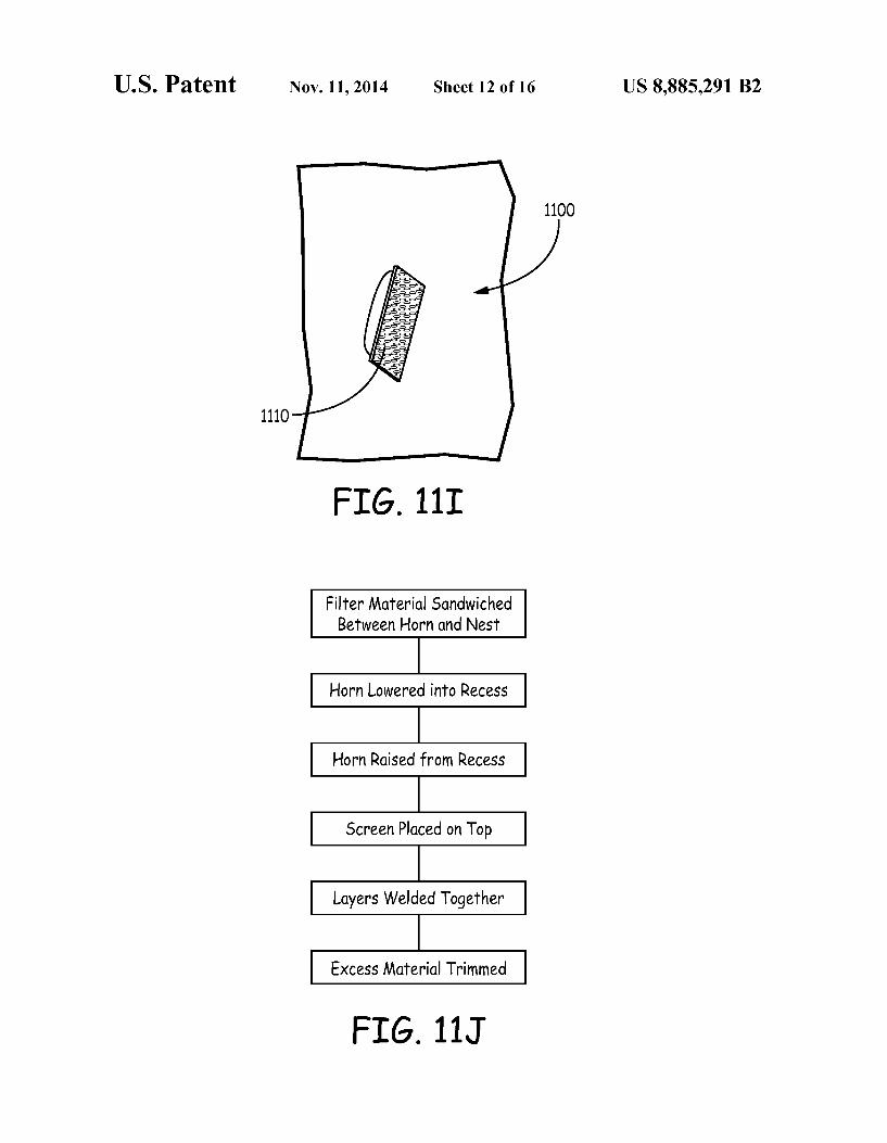
material 1102, such as to sandwich the filter material 1102 between the nest 1104 and the screen layer 1110 (FIG. 11F). The screen layer 1110 can be welded, fused or otherwise bonded to the filter material 1102. In an embodiment, the filter material 1102 comprises an electrostatic layer 1120 and a support layer 1122 and when the screen layer 1110 is welded to the filter material 1102, the electrostatic layer 1120 can be welded to the support layer 1122. The filter assembly can be welded such as along line 1114. The filter assembly can be welded on a plurality of lines 1114. Any excess material beyond the weld line (FIG. 11H) can be removed from the filter assembly, Such as by trimming, resulting in a filter assembly 1100 (FIG. 11I). The screen layer 1110 can partially cover the open end of
the filter assembly. The screen layer 1110 can allow air to pass through the screen layer and into the recess 1106 of the filter assembly. The screen layer 1110 can provide support, such as to aid the filter assembly in keeping a desired configuration.
FIG. 11J shows a flow chart depicting a method of making a filter assembly. A filter material can comprise an electro static layer and a Support layer. The filter material can be sandwiched between a horn and a nest. The horn can be lowered or otherwise moved into a recess in the nest, thereby configuring the filter material to a shape that Substantially resembles the shape of the outer surface of the horn and the shape of the recess in the nest. The horn can be removed from the recess. The filter material can be configured to substan tially retain its shape once the horn is removed from the recess. A screen layer can be place on top of the filter material. The screen layer can cover a portion of the open side of the filter material. The layers can be bonded, such as by welding, together. The filter assembly can be removed from the nest. Excess material can be removed from the filter assembly. A method for making a filter assembly as described herein
is shown schematically in FIGS. 12A to 12G. In this method a sheet of filter material 1202 is provided (FIG. 12A). The sheet of filter material 1202 can comprise an electrostatic layer 1220 and one or more support layer 1222 (such as a
US 8,885,291 B2
scrim layer). The sheet of filter material 1202 can be welded in one or more locations, such as along weld line 1214 (FIG. 12B). The distance between two weld lines 1214 can differ from a first sheet of filter material 1202 to a second sheet of filter material 1202. The method can also include the use of a nest 1204. The
nest 1204 can comprise a recess 1206 (FIG. 12C). The recess 1206 can be shaped similarly to the desired final shape of the filter assembly. A first sheet of filter material 1202 can be placed on the nest 1202. The weld lines 1214 can be perpen dicular to the nest 1204. The first sheet offilter material 1202 can be placed on the nest 1204, such that a portion of the recess 1206 is still exposed. In an embodiment an edge of the first filter sheet (such as a welded line 1214) is aligned with an edge of the nest 1204. The method can comprise the use of a horn 1208 (FIG.
12D). The horn 1208 can have a similar shape as desired final shape of the filter assembly. The sheet of filter material 1202 can be positioned between the horn 1208 and a nest 1204. The horn 1208 can be pressed into the recess 1206, such as to configure the filter material 1202 into a shape that closely resembles the recess 1206 and the horn 1208 (FIG. 12E). A second sheet of filter material 1202 can be placed on top
of the first sheet of filter material 1202, such as to sandwich the horn 1208 in between (FIG. 12F). The first sheet of filter material 1202 can be bonded to the second sheet of filter material 1202, such as by welding along lines 1214. The horn 1208 can be removed from the recess 1206, such as through the open end of the filter assembly. Removing the horn 1208 can define the recess in the filter assembly. Excess material 1216 can be removed from the filter assembly, such as by trimming it, resulting in a filter assembly 1200 (FIG. 12G).
FIG. 12H shows a flow chart depicting a method of making a filter assembly. A filter material can comprise a layer of electrostatic sandwiched between two Support layers (such as two scrim layers). A filter material can include two weld lines, such as one at the front portion of the filter assembly and one at the back portion of the filter assembly. The two weld lines can be parallel. A first sheet of filter material can be disposed on a nest. The nest can comprise a recess. The two weld lines can be positioned perpendicular to the recess. A horn can be inserted into the recess, such as to form the first sheet filter material to closely match the shape of the horn and the recess. A second sheet of filter material can be disposed on top of
the horn and on a portion of the first sheet of filter material. The second sheet of filter material can comprise two weld lines. The weld lines on the second sheet offilter material can be aligned with the weld lines on the first sheet of filter material. The first sheet offilter material can be bonded to the second sheet of filter material. Such as by welding. The horn can be removed from the recess, such as to define
a recess in the filter assembly. The filter assembly can be removed from the nest. Excess material can be removed from filter assembly, Such as by trimming. Experiments
In order to evaluate the performance of filters made in accordance with the present invention, comparisons were made between two comparative recirculation filter elements, and two filter elements made in accordance with the present disclosure.
In the first comparative example, the filter element was a Substantially planar recirculation filter with a polypropylene scrim overlying an electrostatic media. The polypropylene scrim had a permeability of approximately 300 feet per minute at 0.5 inches of water. The electrostatic media had a
5
10
15
25
30
35
40
45
50
55
60
65
10 permeability of approximately 400 feet per minute at 0.5 inches of water. The filter element did not contain an adsor bent material.
In the second comparative example, the filter element also was a Substantially planar recirculation filter with a polypro pylene scrim overlying an electrostatic media. The polypro pylene scrim had a permeability of approximately 500 feet per minute at 0.5 inches of water. The electrostatic media had a permeability of approximately 400 feet per minute at 0.5 inches of water. The filter element did not contain an adsor bent material.
In the single recess filter, a filter element made in accor dance with the present disclosure was produced, the filter element having a substantially conical shape. The filter ele ment included an electrostatic media overlying a polypropy lene scrim on the interior of the filter element. The electro static media had a permeability of approximately 400 feet per minute at 0.5 inches of water. The polypropylene scrim had a permeability of approximately 500 feet per minute at 0.5 inches of water. The filter element did not contain an adsor bent material.
In the multiple recess filter, a filter element made in accor dance with the present disclosure was produced, the filter element had multiple elongate recesses that were substan tially parallel to one another. The filter element included an electrostatic media overlying a polypropylene scrim on the interior of the filter element. The electrostatic media had a permeability of approximately 400 feet per minute at 0.5 inches of water. The polypropylene scrim had a permeability of approximately 500 feet per minute at 0.5 inches of water. The filter element did not contain an adsorbent material.
TABLE 1
Ratio of Percent of Percent of Percent of Trapped to Particles Particles Particles that Reflected Reflected Trapped Fall Out View Particles
Comparative 38.0 29.0 33.0 .76 Example 1 Comparative 3S.O 16.0 49.0 .46 Example 2 Single Recess 34.2 26.7 39.2 .78 Filter Multiple Recess 2O.O 48.3 31.7 2.42 Filter
As indicated in Table 1, the filter constructions with recesses and exposed electrostatic had lower particle reflec tion rates, and also had higher ratios of trapped to reflected particles. Table 1 shows that that the percent of particles reflected from the filter elements was lower for the two ele ments made in accordance with the present disclosure than the two comparative examples: 20.0 and 34.2 compared to 35.0 and 38.0. In addition, both filter elements made inaccor dance with the present disclosure showed a higher ratio of trapped to reflected particles: 2.42 and 0.78 compared to 0.76 and 0.46. Thus, the two example elements made in accor dance with present disclosure demonstrated improved removal of particulate contaminants compared to the two comparative examples. The above specification provides a complete description of
the manufacture and use of the invention. Since many embodiments of the invention can be made without departing from the spirit and scope of the invention the invention resides in the claims hereinafter appended.
US 8,885,291 B2 11
The invention claimed is: 1. A filter assembly for use in an electronic enclosure, the
filter assembly comprising: a media structure including a substantially open front face,
a closed rear face, and an internal recess between the open front face and closed rear face;
a scrim material forming at least a portion of the media structure; and
an electrostatic material disposed within the internal recess of the filter assembly, the electrostatic material at least partially covering the scrim.
2. The filter assembly of claim 1, wherein the scrim mate rial comprises a woven material.
3. The filter assembly of claim 1, wherein the scrim mate rial comprises a non-woven material.
4. The filter assembly of claim 1, wherein the scrim mate rial comprises polypropylene fibers.
5. The filter assembly of claim 1, wherein the scrimmate rial has a permeability of between about 100 ft./min. at 0.5 inches of water and about 800 ft./min. at 0.5 inches of water.
6. The filter assembly of claim 1, wherein the internal recess of the filter assembly has a ratio of maximum length to maximum diameter of the open front face of at least 1.0.
7. The filter assembly of claim 1, wherein the internal recess of the filterassembly has an internal surface area that is at least 2 times the area at the open front face.
8. The filter assembly of claim 1, wherein at least 50 per cent of the surface area of the internal recess has an angle to the opening that is less than or equal to 45 degrees.
9. The filter assembly of claim 1, wherein at least 50 per cent of the Surface area of the internal recess has an angle to the opening that is less than or equal to 30 degrees.
10. The filter assembly of claim 1, wherein the filter assem bly comprises a plurality of structures including an open front face, a closed rear face, and a plurality of internal recesses between the open front face and closed rear face.
11. A filter assembly for use in an electronic enclosure, the filter assembly comprising:
a media structure including a substantially open front end, a closed rear end, and a plurality of internal recesses between the open front face and closed rear face:
a scrim material forming at least a portion of the internal recesses; and
5
10
15
25
30
35
40
12 an electrostatic material disposed within the internal
recesses of the filter assembly, the electrostatic material at least partially covering the scrim.
12. The filter assembly of claim 11, wherein the scrim material comprises woven material.
13. The filter assembly of claim 11, wherein the electro static material has a filtering efficiency of about 20% to about 99.99% for 20 to 30 micron particulate contaminants.
14. The filter assembly of claim 11, wherein at least one of the plurality of internal recesses has a ratio of maximum length to maximum diameter of the open front face of at least 1.O.
15. The filter assembly of claim 11, wherein at least one of the plurality of internal recesses has an internal surface area that is at least 2 times the area at the open front face.
16. The filter assembly of claim 11, wherein at least one of the plurality of internal recesses has an internal surface area that is at least 4 times the area at the open front face.
17. The filter assembly of claim 11, wherein at least one of the plurality of internal recesses has an internal surface area that is at least 6 times the area at the open front face.
18. The filter assembly of claim 11, wherein at least 50 percent of the surface area of at least one internal recess has an angle to the opening that is less than or equal to 45 degrees.
19. The filter assembly of claim 11, wherein at least 50 percent of the surface area of at least one internal recess has an angle to the opening that is less than or equal to 30 degrees.
20. A disk drive assembly, the disk drive assembly com prising:
(a) a disk drive housing that defines an enclosure; (b) at least one disk rotatably mounted within the enclo
Sure, wherein rotation of the at least one disk induces airflow within the enclosure; and
(c) a filter assembly disposed within the enclosure, wherein the filter assembly comprises:
a media structure including a substantially open front face. a closed rear face, and an internal recess between the open front face and closed rear face;
a scrim material forming at least a portion of the media structure;
an electrostatic material disposed within the internal recess of the filter assembly, the electrostatic material at least partially covering the scrim material.