111111111111111111111111111111111111111111111111111111111111111111111111 (12) United States Patent Nguyen et al. (54) AEROELASTIC WING SHAPING USING DISTRIBUTED PROPULSION (71) Applicant: The United States of America as Represented by the Administrator of the National Aeronautics and Space Administration, Washington, DC (US) (72) Inventors: Nhan T. Nguyen, Santa Clara, CA (US); Kevin Wayne Reynolds, Menlo Park, CA (US); Eric B. Ting, Moffett Field, CA (US) (73) Assignee: The United States of America as Represented by the Administrator of NASA, Washington, DC (US) (*) Notice: Subject to any disclaimer, the term of this patent is extended or adjusted under 35 U.S.C. 154(b) by 0 days. (21) Appl. No.: 14/986,011 (22) Filed: Dec. 31, 2015 Related U.S. Application Data (60) Provisional application No. 62/119,013, filed on Feb. 20, 2015. (51) Int. Cl. B64C 3/52 (2006.01) B64C 3/10 (2006.01) B64C 3/32 (2006.01) B64C 15/02 (2006.01) B64D 27/24 (2006.01) B64C 9100 (2006.01) (52) U.S. Cl. CPC .................. B64C 3/52 (2013.01); B64C 3/10 (2013.01); B64C 3/32 (2013.01); B64C 15/02 (2013.01); B64D 27/24 (2013.01); B64C 20091005 (2013.01) (io) Patent No.: US 9,751,614 B1 (45) Date of Patent: Sep. 5, 2017 (58) Field of Classification Search None See application file for complete search history. (56) References Cited U.S. PATENT DOCUMENTS 9,227,721 131 * 1/2016 Nguyen .................... B64C 9/14 2002/0005454 Al* 1/2002 MacCready .............. B64C 1/26 244/5 2004/0118969 Al* 6/2004 MacCready .............. B64C 1/26 244/5 2009/0261205 Al* 10/2009 Pitt ........................... B64C 3/52 244/203 2014/0084115 Al* 3/2014 Sanchez .................... B64C 9/00 244/76 R 2015/0144742 Al* 5/2015 Moxon .................. B64D 27/12 244/215 * cited by examiner Primary Examiner Nicholas Kiswanto Assistant Examiner Tamara Weber (74) Attorney, Agent, or Firm Christopher J. Menke; Robert M. Padilla; Mark P. Dvorscak (57) ABSTRACT An aircraft has wings configured to twist during flight. Inboard and outboard propulsion devices, such as turbofans or other propulsors, are connected to each wing, and are spaced along the wing span. A flight controller indepen- dently controls thrust of the inboard and outboard propulsion devices to significantly change flight dynamics, including changing thrust of outboard propulsion devices to twist the wing, and to differentially apply thrust on each wing to change yaw and other aspects of the aircraft during various stages of a flight mission. One or more generators can be positioned upon the wing to provide power for propulsion devices on the same wing, and on an opposite wing. 20 Claims, 32 Drawing Sheets 100 120B' -~► s } 110 https://ntrs.nasa.gov/search.jsp?R=20170009508 2018-05-22T07:12:32+00:00Z
(71) Applicant: The United States of America asRepresented by the Administrator ofthe National Aeronautics and SpaceAdministration, Washington, DC (US)
(72) Inventors: Nhan T. Nguyen, Santa Clara, CA(US); Kevin Wayne Reynolds, MenloPark, CA (US); Eric B. Ting, MoffettField, CA (US)
(73) Assignee: The United States of America asRepresented by the Administrator ofNASA, Washington, DC (US)
(*) Notice: Subject to any disclaimer, the term of thispatent is extended or adjusted under 35U.S.C. 154(b) by 0 days.
(21) Appl. No.: 14/986,011
(22) Filed: Dec. 31, 2015
Related U.S. Application Data
(60) Provisional application No. 62/119,013, filed on Feb.20, 2015.
(74) Attorney, Agent, or Firm Christopher J. Menke;Robert M. Padilla; Mark P. Dvorscak
(57) ABSTRACT
An aircraft has wings configured to twist during flight.Inboard and outboard propulsion devices, such as turbofansor other propulsors, are connected to each wing, and arespaced along the wing span. A flight controller indepen-dently controls thrust of the inboard and outboard propulsiondevices to significantly change flight dynamics, includingchanging thrust of outboard propulsion devices to twist thewing, and to differentially apply thrust on each wing tochange yaw and other aspects of the aircraft during variousstages of a flight mission. One or more generators can bepositioned upon the wing to provide power for propulsiondevices on the same wing, and on an opposite wing.
This application claims the benefit of U.S. ProvisionalApplication No. 62/119,013, filed Feb. 20, 2015, the con-tents of which are incorporated herein in their entirety.
ORIGIN OF INVENTION
The invention described herein was made in the perfor-mance of work under a NASA contract and by (an) employ-ee(s) of the United States Government and is subject to theprovisions of §20135(b) of the National Aeronautics andSpace Act, Public Law 111-314, §3 (124 Star. 3330, 51U.S.C. Chapter 201), and may be manufactured and used byor for the Government for governmental purposes withoutthe payment of any royalties thereon or therefore.
BACKGROUND OF THE DISCLOSURE
Technical Field of the DisclosureThe present invention relates to flexible wing shaping,
and more particularly to using propulsion distributed alongthe wing to propel the vehicle and change wing shape.
Description of the Prior ArtThe Wright brothers who invented the first aircraft real-
ized the advantages of shape changing bird wings in flightcontrol. They designed a wing warping flight control systemto warp a wing by cables to change aircraft directions.
In modern time, NASA had developed a shape changingwing technology in the 1980's under the Mission AdaptiveWing program, which demonstrated a variable camber tech-nology on the F-111 aircraft. The variable camber designallows the wing shape to change in order to adapt to differentmissions.A NASA program in the early 2000's called Active
Aeroelastic Wing developed a method for elastically shapea flexible wing to perform roll control. The concept is basedon using leading edge slats and ailerons to twist highlymodified flexible wings of an F-18 aircraft to generatedifferential lift for roll control.
In recent years, the Boeing 787 aircraft employs a light-weight, flexible wings that can flex substantially duringflight. During certification testing, the wings flexed 25 ftupward under a proof load of 150% of the design load.The NASA Helios prototype is an ultra-lightweight flying
wing aircraft with a wingspan of 247 ft. A slight upwardtwist at the tips of the trailing edge helps prevent wing tipstalls during slow landings and turns. The flying wingaircraft is assembled in six sections, each about 41 ft long.A series of propellers are mounted at the joints of the wingpanels. An underwing pod is attached at each panel joint tocarry the landing gear, the battery power system, flightcontrol computers, and data instrumentation.To turn the Helios aircraft in flight, yaw control is applied
by applying differential power on the motors speeding upthe motors on one outer wing panel while slowing downmotors on the other outer panel. A major test during theinitial flight series was the evaluation of locally varyingmotor power as a means of pitch control. During normalcruise the outer wing panels of Helios are arched upward andgive the aircraft the shape of a shallow crescent whenviewed from the front or rear. This configuration places themotors on the outer wing panels higher than the motors on
2the center panels. Speeding up the outer-panel motorscaused the aircraft to pitch down and begin a descent.Conversely, applying additional power to the motors in thecenter panels caused Helios to pitch up and begin climbing.
5
SUMMARY OF THE INVENTION
In an embodiment of the disclosure, an aircraft comprisesat least two wings, each wing configured to twist during
io flight along a portion of the length of the wing; at least oneinboard propulsion device connected to each wing, locatedat some distance along the wing span; at least one outboardpropulsion device connected to each wing, located at somedistance along the wing span, the at least one outboard
15 propulsion device positioned closer to a wing tip of the wingto which it is connected than the at least one inboardpropulsion device; and a controller configured to indepen-dently control thrust of the at least one outboard propulsiondevice and the at least one inboard propulsion device,
20 including controlling thrust of the at least one outboardpropulsion device to produce the twist to thereby signifi-cantly change flight dynamics of the aircraft while main-taining aeroelastic stability.In variations thereof, the propulsion devices are posi-
25 tioned in the chordwise direction relative to the wing airfoil;the inboard and the outboard propulsion devices are posi-tioned on at least one of the upper, lower, or both surfacesof the wing; the controller is configured to independentlycontrol thrust of the at least one inboard propulsion device
3o and the at least one outboard propulsion device, to change ayaw angle of the aircraft while maintaining lift of theaircraft; the controller is configured to independently controlthrust of each of the at least one inboard propulsion deviceand each of the at least one outboard propulsion device for
35 each wing, to thereby control flight dynamics of the aircraftin the event of failure of at least one inboard or outboardpropulsion device; and/or the controller is configured toindependently control thrust of the at least one outboardpropulsion device and the at least one inboard propulsion
4o device to thereby twist and change the shape of the wings toimprove L/D during at least one of takeoff, cruise, andlanding of the aircraft while maintaining aeroelastic stabil-ity.
In other variations thereof, the at least one inboard pro-45 pulsion device and the at least one outboard propulsion
device include at least four propulsion devices; the at leastone inboard propulsion device and the at least one outboardpropulsion device are electric fan engines; the aircraft fur-ther includes at least one electricity generator configured to
50 generate electricity to operate the electric fan engines; thereare at least one generator connected to each wing; thegenerator is configured to produce maximum electricity andminimum thrust; the generator is connected to a transformer,and the transformer is connected to a battery, and the electric
55 fan engines are connected to the battery; the transformer isa step-down transformer; electricity generated by the gen-erator is passed to the controller; at least one of the at leastone outboard propulsion device is located proximate thewing tip; and/or at least one of the at least one inboard
60 propulsion device or the at least one outboard propulsiondevice is an electric fan engine.In a yet further embodiment thereof, the electrical system
of the aircraft includes a battery configured to provideelectricity to an electric fan engine; the aircraft further
65 includes at least one propulsion device proximate a tip of thewing forming a winglet operative to reduce wing tip vorticesfor drag reduction; and/or the aircraft further includes at one
US 9,751,614 B1
3propulsion device and a thrust vector flap positioned directlybehind the propulsion device to generate the vertical liftcomponent to change the wing bending shape.
In another embodiment thereof, the aircraft furtherincludes at least one propulsion device configured to imparta lateral thrust force to create bending moment to change theshape of the wings to improve L/D during at least one oftakeoff, cruise, and landing of the aircraft while maintainingaeroelastic stability. In variations thereof, the lateral thrustcomponent is created by at least one propulsion device thatcan be articulated so that the thrust vector is at an anglerelative to the aircraft axis; the lateral thrust component iscreated by at least one propulsion device equipped with athrust vectoring nozzle; and/or the lateral thrust componentis created by at least one propulsion device equipped with athrust vectoring plate positioned directly behind the propul-sion device and made pivotable in an axis perpendicular tothe wing planform.
In another embodiment of the disclosure, a method ofchanging flight dynamics during flight of an aircraft, com-prises providing an aircraft having: at least one inboardpropulsion device connected to each wing; at least oneoutboard propulsion device connected to each wing, the atleast one outboard propulsion device positioned closer to awing tip of the wing to which it is connected than the at leastone inboard propulsion device; two wings each configuredto twist during flight along a portion of a length of the wingusing the at least one outboard propulsion device; and acontroller configured to independently control thrust of theat least one outboard propulsion device and the at least oneinboard propulsion device, including controlling thrust of atleast the at least one outboard propulsion device to cause thetwist during flight.
In variations thereof, twisting is carried out by the con-troller by applying at least 50% more thrust to the at leastone outboard propulsion device and at least 50% less thrustto the at least one inboard propulsion device; the controlleris configured for distributing power to reduce or eliminateasymmetric thrust due to power loss; the controller isconfigured for carrying out a coordinated turn control usingasymmetric thrust only; the controller is configured for yawcontrol using asymmetric thrust in coordination with con-trolling aileron positioning; the controller is configured foryaw control using asymmetric thrust in coordination withcontrolling rudder positioning; and/or the controller is con-figured for changing propulsion distribution and thrust-induced lift, and aileron and rudder positioning, to achieveoverall flight control in the lateral-directional motion.
BRIEF DESCRIPTION OF THE DRAWINGS
The accompanying figures, where like reference numeralsrefer to identical or functionally similar elements throughoutthe separate views, and which together with the detaileddescription below are incorporated in and form part of thespecification, serve to further illustrate various embodimentsand to explain various principles and advantages all inaccordance with the present disclosure, in which:
FIG. 1A to 1D depict perspective views of a model of anembodiment of an aircraft having distributed thrust andflexible wings of the disclosure, the aircraft in flight;
FIG. 2 depicts a propulsion device of the disclosure thatcan generate lateral thrust;
FIG. 3A depicts a thrust vectoring nozzle in accordancewith the disclosure;FIG. 3B depicts a thrust vectoring plate of the disclosure;
4FIG. 4 depicts an alternative thrust vectoring plate of the
disclosure;FIG. 5 depicts a multidisciplinary approach to design of
an aircraft of the disclosure, illustrating relationships among5 the various disciplines;
FIG. 6 depicts an embodiment of an aircraft of thedisclosure;FIG. 7 depicts planform geometry of a wing as used in a
modeling tool of the disclosure;to FIG. 8 depicts pressure distribution on a wing using the
modeling tool of FIG. 7;FIG. 9 depicts vertical lift distribution using the modeling
tool of FIG. 7;15 FIG. 10 depicts lift curves using the modeling tool of FIG.
7;FIG. 11 depicts drag polars using the modeling tool of
FIG. 7;FIG. 12 depicts an aerodynamic analysis of the disclosure
20 of a prior art baseline generic transport model (GTM);FIG. 13 depicts the aerodynamic analysis of FIG. 12, of
an embodiment of the disclosure having 2 generators andfour propulsors per wing;
FIG. 14 depicts the aerodynamic analysis of FIG. 12, of25 an embodiment of the disclosure having 1 generators and
three propulsors per wing, all of which are oriented close tothe wing root;
FIG. 15 depicts the aerodynamic analysis of FIG. 12, ofan embodiment of the disclosure having a single generator
so positioned close to the wing root, and four propulsors evenlyspaced along the wing, including a propulsor positionedproximate the wing tip;FIGS. 16A-16D depict propulsion interaction with wing
aerodynamics, in which FIG. 16A illustrates the interaction35 for a wing without propulsors or generators, FIG. 16B
illustrates the GTM, FIG. 16C illustrates the embodiment ofFIG. 13, and FIG. 16D illustrates the embodiment of FIG.14;FIG. 17-18 shows equations used by modeling of the
4o disclosure to determine a required fan configuration ofsuitable thrust for the embodiment being modeled;FIG. 19 is a plot of turbofan weight and diameter using the
equations of FIGS. 17-18;FIG. 20 is a plot of turbofan thrust at sea level for various
45 fan pressure ratios;FIG. 21 depicts various components of an electrically
propelled aircraft of the disclosure;FIGS. 22-25 depict various configurations for an electri-
cally propelled aircraft of the disclosure;50 FIG. 26 depicts an embodiment of an aircraft configura-
tion of the disclosure;FIG. 27 depicts transformer weight and power for various
configurations of an electrically propelled aircraft of thedisclosure;
55 FIG. 28 depicts a pie chart of an illustrative distributionof weight for components of an electrically propelled air-craft of the disclosure;FIG. 29 depicts an arrangement of components relating to
electrical propulsion of an aircraft of the disclosure;60 FIGS. 30-31 depict a finite-element model of a flexible
wing using geometry generation tools of the disclosure;FIGS. 32-33 depict a model of the disclosure illustrating
an integrated finite-element aeroelastic model for 6 degreesof freedom deformation capability for a flexible wing of the
65 disclosure;FIGS. 34-35 depict an interactive user interface for a
static aeroelastic modeling tool of the disclosure, the mod-
FIG. 36 illustrates a multidisciplinary design analysis andoptimization matrix;
FIG. 37 illustrates design variables for wings, propulsion,and trajectory used in modeling of the disclosure;
FIG. 38 is an equation used in modeling in accordancewith the disclosure, incorporating aero-propulsive-elasticinteractions for thrust-induced lift force, thrust-induced elas-tic deformation, and thrust-induced angle of attack;
FIG. 39 is an equation used in modeling in accordancewith the disclosure, for determining a local aeroelastic angleof attack;
FIG. 40 is an equation used in modeling twistingmoments, in accordance with the disclosure;FIG. 41 is an equation used in modeling bending
moments, in accordance with the disclosure;FIG. 42 depicts an aircraft embodiment of the disclosure
having one generator per wing, and four spaced propulsors;FIG. 43 depicts an aircraft embodiment of the disclosure
having two generators per wing, each generator flanked bytwo propulsors;
FIG. 44 is an equation of the disclosure for modelingsensitivity of thrust-induced lift with propulsor spacing;FIG. 45 depicts an alternative view of the aircraft of FIG.
42;FIG. 46 is a plot of thrust-induced lift and propulsor
spacing for various values of bending (EI) and torsionalstiffness (G7);FIG. 47 is a plot of thrust-induced lift and propulsor
spacing, for various distributions of thrust along the wing-span;FIGS. 48-51 are plots depicting the effect of wing stiffness
on lift-to-drag ratio, where various levels of thrust areapplied by propulsors distributed along the wing, and inwhichFIG. 48 shows lift distribution along a stiff wing;FIG. 49 shows aerodynamic efficiency at various angles
of attack, for a stiff wing;FIG. 50 shows lift distribution along a flexible wing; andFIG. 51 shows aerodynamic efficiency at various angles
of attack, for a flexible wing;FIGS. 52-55 are plots depicting relative improvement of
L/D for embodiments of the disclosure over a baselineaircraft configuration, where various levels of thrust areapplied by propulsors distributed along the wing, and inwhichFIG. 52 depicts a stiff wing having 1 generator and 4 fans
per wing;FIG. 53 depicts a stiff wing having 2 generators and 4 fans
per wing;FIG. 54 depicts a flexible wing having 1 generator and 4
fans per wing; andFIG. 55 depicts a flexible wing having 2 generators and 4
fans per wing;FIGS. 56-58 relate to trajectory optimization, in whichFIG. 56 is a plot of an optimized climb out;FIG. 57 depicts a formula for calculating the climb out of
FIG. 56, and particularly a maximum thrust climb along anoptimal singular arc; and
FIG. 58 is a plot of an optimized descent;FIGS. 59-62 pertain to analyzing cruise range for various
levels of thrust applied by propulsors distributed along awing with a single generator, and in whichFIG. 59 is a plot of range and cruise altitude for an aircraft
embodiment having a stiff wing;
6FIG. 60 is a plot of range and cruise altitude for an aircraft
embodiment having a flexible wing;FIG. 61 is Breguet's range equation; andFIG. 62 is a formula for specific thrust fuel consumption
5 for turbofan engines;FIG. 63 is a table of an analysis of L/D for stiff and
flexible winged embodiments, for single and dual genera-tors, and for various alternatives of thrust distributions;FIG. 64 is a plot of data of FIG. 63;
10 FIG. 65 is a plot cruise altitude and aircraft weight, forvarious distributions of thrust along the wingspan, to illus-trate maximum L/D cruise trajectories, for an aircraftembodiment of the disclosure having a single generator andfour propulsors per wing, and a flexible wing;
15 FIG. 66 is a plot as in FIG. 66, but for a stiff wing;FIG. 67 is a plot of flutter and propulsor spacing, for
symmetric and anti-symmetric modes of an aircraft embodi-ment of the disclosure with 1 generator near the wing root,and 4 fans equally spaced inboard from the wingtip, for a
20 stiff wing;FIG. 68 is a plot as in FIG. 66, but for a flexible wing;FIG. 69 is a plot of frequency and speed, for an aircraft of
the disclosure having flexible wings and 10 foot propulsorspacing;
25 FIG. 70 is a plot of damping ratio and speed, for anaircraft of the disclosure having flexible wings and 10 footpropulsor spacing, for varying alternatives of thrust alongthe wing;
FIG. 71 is a plot of fuel reduction and range, for a flexible30 wing, single generator aircraft of the disclosure when cruis-
ing at a constant L/D;FIG. 72 is a plot as in FIG. 73, but for dual generators;FIG. 73 illustrates a power distribution scheme of the
disclosure for a configuration having a single generator per35 wing;
FIG. 74 illustrates asymmetric thrust yaw control inaccordance with the disclosure;FIG. 75 illustrates asymmetric thrust to create unequal lift
forces in accordance with the disclosure;40 FIG. 76 illustrates asymmetric thrust forces acting to
produce nose-up pitching moments, in accordance with thedisclosure;FIG. 77 is a block diagram of a flight control system of the
disclosure; and45 FIG. 78 is an illustrative computer system, part or all of
which can be used to carry out various aspects of thedisclosure, including the flight control system of FIG. 77.
DETAILED DESCRIPTION OF THE50 INVENTION
As required, detailed embodiments are disclosed herein;however, it is to be understood that the disclosed embodi-ments are merely examples and that the systems and meth-
55 ods described below can be embodied in various forms.Therefore, specific structural and functional details dis-closed herein are not to be interpreted as limiting, but merelyas a basis for the claims and as a representative basis forteaching one skilled in the art to variously employ the
60 present subject matter in virtually any appropriately detailedstructure and function. Further, the terms and phrases usedherein are not intended to be limiting, but rather, to providean understandable description of the concepts.The terms "a" or "an", as used herein, are defined as one
65 or more than one. The term plurality, as used herein, isdefined as two or more than two. The term another, as usedherein, is defined as at least a second or more. The terms
US 9,751,614 B1
7"including" and "having," as used herein, are defined ascomprising (i.e., open language). The term "coupled," asused herein, is defined as "connected," although not neces-sarily directly, and not necessarily mechanically. The figuresherein are drawn for ease of understanding, and are notdrawn to scale or proportion.
In accordance with the disclosure, distributed propulsionand lightweight structures on air-breathing air vehicles posea significant opportunity to improve mission performancewhile meeting next generation requirements includingreduced fuel burn, lower emissions and enhanced takeoffand landing performance. Flexible wing-shaping aircraftusing distributed propulsion enable the ability to achieveimproved aerodynamic efficiency while maintainingaeroelastic stability. Wing shaping concepts using distrib-uted propulsion leverage the ability to introduce forces/moments into the wing structure to affect the wing aerody-namics.
Further in accordance with the disclosure, wing shapingcan be performed throughout the flight envelope to affectlocal angle of attack as the wing loading changes with airvehicle weight during cruise. By softening the structuralstiffness of an unoptimized wing geometry, the inventorshave demonstrated using trajectory optimization that thisconcept could achieve about a 4% improvement in lift-to-drag ratio, or L/D, compared with a stiff wing design acrossa mission profile consisting of a minimum fuel climb, cruise,and continuous descent. The reduction in fuel burn can beattributed to a reduction in lift-dependent drag throughoutthe flight envelope by actively tailoring the spanwise liftdistribution using distributed propulsion. The disclosureenables synergistic interactions between lightweight mate-rials, electric propulsion, and active aeroelastic tailoring forreducing the environmental impact of future air vehicles.
In accordance with the disclosure, flexible wing shapingis achieved using propulsion distributed along the wing topropel the vehicle and change the wing shape. This achievesimproved aerodynamic efficiency and increased lift. More-over, a method for combined roll-yaw control of an aircraftusing distributed propulsion by taking advantage of wingflexibility is disclosed.
Birds in nature have wings, which flex during flight. Birdsperform their flight maneuvers by changing their wingshapes continuously based on their needs. Shape changingbird wings have inspired many aircraft designers since theearly days of manned flight. In accordance with the disclo-sure, highly elastic flexible bird wings suggest, in part,advantages that have not been emulated in past and currentaircraft design, including advantages of flexible wing shap-ing control, and which are disclosed herein.
It has further been determined, in accordance with thedisclosure, that the prior art did not suggest, for example, atleast elastically shaping flexible wings for mission perfor-mance, or aerodynamic performance for twisting ailerons, asthese can generate increased drag.
In an embodiment of the disclosure, distributed electricpropulsion for transport aircraft poses a significant oppor-tunity to meet next generation requirements includingreduced fuel emissions and enhanced takeoff and landingperformance. Since current electric motors produce only afraction of the power output of combustion engines ofsimilar size, future hybrid electric propulsion engines areexpected to be smaller in size and distributed along thewingspan.The concept of "generalized force" is associated with the
effective force acting on a flexible structure. By definition,the generalized force is an integral product of all forces
8acting on a structure and a corresponding mode shape. Thestatic mode shape of a wing structure is a monotonicallyincreasing function from zero at the wing root to a maximumvalue at the wing tip. Thus, as thrust is applied further away
5 from the wing root, the generalized thrust force alsoincreases. If not carefully considered, increasing the gener-alized thrust force can cause undesired wing twist, leadingto sub-optimal lift distributions and/or inadvertent stall. Animportant example is the Helios aircraft that crashed due to
to aeroelastic effects unaccounted for in the control laws. Thedisclosure provides an effective design and methods foraddressing these challenges.The concept of "generalized mass" is associated with the
15 effective mass of a flexible structure. By definition, thegeneralized mass is an integral product of all masses thatcomprise a structure and a corresponding mode shape.Distributed propulsion results in the placement of a pluralityof propulsion devices along a wing span. Thus, the gener-
20 alized mass associated with distributed propulsion dependson the placement of the propulsion devices as well as a givendynamic mode shape.The concept of "generalized stiffness" is associated with
the effective stiffness of a flexible structure. By definition,25 the generalized stiffness for bending is an integral product of
all stiffness contributions and the second derivative of acorresponding bending mode shape, and the generalizedstiffness for torsion is an integral product of all stiffnesscontributions and the first derivative of a corresponding
30 torsion mode shape. As the pitching moment created by athrust force causes a wing section to twist, the orientation ofthe thrust vector also changes. This results in a force-follower effect that creates a thrust-induced stiffness. Thus,the thrust-induced generalized stiffness associated with dis-
35 tributed propulsion depends on the placement of the pro-pulsion devices as well as a given dynamic mode shape.
If not carefully considered, changes in the generalizedmass and stiffness can result in adverse aeroelastic stabilityinteractions known as flutter which is a dynamic aeroelastic
40 instability associated with unstable vibration and divergencewhich is a static aeroelastic instability associated withunstable static deflection of a flexible structure. Aircraft aredesigned to meet flutter certification requirements to ensureflutter free operation inside a flight envelope. The disclosure
45 provides an integrated design and methods for addressingthese challenges.The disclosure additionally provides for creating fuel
optimal trajectories that take into account the potentialadverse interaction between distributed propulsion and wing
50 flexibility. By explicitly including this interaction in missiondesign, it is possible to avoid a resulting increase in energyconsumption which otherwise could diminish the benefits ofdistributed propulsion.The disclosure enables, for example, development of a
55 flexible wing generic transport aircraft model with distrib-uted electric propulsion operating at cruising speed of Mach0.8, and with a cruise ceiling of 35,000 ft. Additionally, thedisclosure enables the design of a fuel-optimal missionprofile comprised of climb, cruise, and continuous descent
6o by performing trajectory optimization that accounts for wingaeroelasticity and performance parameters, to obtain anoptimal thrust distribution along the wingspan.The disclosure can be used to create, for example, a
distributed propulsion model with dynamic aeroelasticity for65 flutter analysis in Matlab, and a trajectory generation algo-
9The disclosure provides a flexible wing-shaping aircraft
able to achieve improved aerodynamic efficiency whilemaintaining aeroelastic stability using distributed propul-sion. The propulsive moments produced from a set ofdistributed propulsion devices mounted along the wing can 5
be used to optimize L/D by modifying wing twist andbending.
With reference to FIGS. 1A-1D, an embodiment of thedisclosure includes an air breathing aircraft 100 having aplurality of inboard turbofan engine cores (shown one per iowing only for illustration) which serve as generators 110 forpowering propulsion devices 120 which could be electricfans distributed along the outboard section of each wing 130.
The disclosure provides examples using a baseline aircrafthaving characteristics of a Boeing 757; however, it should be 15understood that the disclosure can be carried out with a widevariety of aircraft. A variety of configurations of differingnumbers and locations of turbofans and propulsion devices,extent of thrust, and nacelle sizes, and placement along thewing span either above or below wing and either forward or 20aft of the wing leading edge or trailing edge can be providedalong the wing, to meet applicable requirements for takeoff,climb, and cruise performance. Thus, the illustrated place-ment below the wings illustrates just one possible placementembodiment. In accordance with the disclosure, as wing 25flexibility increases, thrust distribution can be made tochange the wing local angle of attack significantly, so as toaffect aircraft performance in a beneficial way.
In accordance with the disclosure, engine placement nearthe wing tip will typically produce larger generalized forces 30for wing shaping, while engine placement closer to the wingroot, where the generalized mass and is low, is morefavorable for aeroelastic stability from flutter consideration.Optimization of desired characteristics includes selecting aplacement location along the wing for each propulsion 35device and generator to balance these attributes and achievewing shaping control effectiveness while maintaining suffi-cient aeroelastic stability.
For a distributed propulsion layout and wing planform,wing torsion and bending stiffness properties are optimized 40for both weight reduction and lift distribution for a cruiseconfiguration to take advantage of distributed propulsionwing shaping. This is in contrast to the ordinary skill of theart which does not take advantage distributed propulsionwing shaping. For example, a conventional stiff wing cannot 45be easily exploited by distributed propulsion wing shapingthan a wing structure that is specifically tailored aeroelasti-cally to exploit the aeroelastic-propulsive interactions forbeneficial purposes. An aeroelastic-propulsive model can bedeveloped in accordance with the disclosure to capture the 50aeroelastic-propulsive interactions on the wing. For optimi-zation studies, this model can be coupled with an aircraftaerodynamic model to assess aircraft performance in termsof the quantity L/D.The wing stiffness, jig-shape twist distribution, and thrust 55
distribution are tailored in a synergistically way to get anoptimal lift distribution in the presence of distributed pro-pulsion. For under-wing mounted propulsion, a positivenose-up twist is generated. On the hand, the aeroelasticwash-out twist due to bending and torsion is normally 60negative nose-down. Thus, the jig-shape twist, that is thegeometric twist of a wing in manufacture, must be designedto account for the positive twist due to under-wing mounteddistributed propulsion. This would imply a more negativenose-down jig-shape twist. Current transport aircraft typi- 65cally has a jig-shape twist that varies from about 2 to 3degrees at the wing root to about —3 to —5 degrees at the
10wing tip. With under-wing mounted distributed propulsion,depending on the wing stiffness and thrust distribution, atypical jig-shape twist could be tailored to have morenegative twist at the wing tip.The converse is true for over-wing mounted distributed
propulsion which creates a negative nose-down twist. In thiscase, the jig-shape twist could be tailored to have lessnegative nose-down twist.In accordance with the disclosure, the wing stiffness,
jig-shape twist distribution, thrust distribution, and place-ment of the distributed propulsion devices are to be designedin an integrated and synergistic manner by employing anaeroelastic-propulsive model coupled with an aerodynamicmodel. Any of these design parameters can be exploited inthe design to attain maximum aerodynamic benefits bytaking advantage of distributed propulsion wing shaping.
It should be understood that the thrust distribution can betailored in any advantageous orientation relative to theaircraft fuselage centerline. While one preferred embodi-ment discloses a method of applying distributed propulsionwith the thrust vector orientation that lies on the symmetricplane of the aircraft, it is also possible that alternate embodi-ments teach a method of applying distributed propulsion indifferent orientations. For example, one embodiment dis-closes a concept utilizing one or more propulsion devicesgenerating thrusts with a lateral component normal to thesymmetric plane of the aircraft. This lateral thrust compo-nent can be exploited in a number of advantageous ways toimprove aerodynamic efficiency L/D and aircraft flightcontrol. One such method is to take the advantage of lateralthrust component to create a bending moment that acts toincrease or decrease bending of a wing actively to shape thewing wash-out twist distribution for optimal aerodynamicperformance. For example, an outward lateral thrust com-ponent of an under-wing mounted propulsion device willcreate a positive bending moment to increase bending.Another method is to accomplish a yaw control by differ-entially applying the lateral thrust component to create ayawing moment and a side force to yaw an aircraft withoututilizing a rudder for yaw control.One embodiment of a propulsion device that can generate
a lateral thrust component is as shown in FIG. 2, whichillustrates wing 130 with a generator 110 and a plurality ofpropulsion devices 120 arranged as disclosed elsewhereherein, only one of which is shown in the illustration ofFIGS. 2-3, for clarity. In particular, the propulsion device120 of FIG. 2 has the ability to rotate in a plane parallel tothe wing planform about a fixed or non-fixed point. Whenthe propulsion device 120 is rotated away from the thrustcenterline, a lateral thrust component is created for thepurpose of introducing additional bending moment tochange the wing bending shape, or for generating a sideforce and a yawing moment. The propulsion devices can beindividually adjusted in their rotation to create any desiredbending moment distribution or side force and yawingmoment.
Another embodiment is illustrated in FIG. 3A whichshows a propulsion device 120 equipped with a thrustvectoring nozzle 124 that can be oriented to the left or rightin order to generate a lateral thrust component. In particular,thrust vectoring nozzle 124 creates a momentum force in thelateral direction as the fluid leaves the nozzle at an anglerelative to the flow direction. In other embodiments, nozzle124 can additionally or alternatively be moved up and downfor wing shaping or to create momentum force in otherdirections.
US 9,751,614 B111
In yet another embodiment, shown in FIG. 313, a thrustvectoring plate 126 is used to generate a lateral thrustcomponent by redirecting thrust from propulsion device120. Thrust vectoring plate 126 has the ability to rotate abouta fixed or non-fixed point through an axis perpendicular tothe wing planform. As the thrust vectoring plate 126 isrotated away from the thrust centerline, the exhaust flowimpinging on the thrust vectoring plate 126 creates a liftforce perpendicular to, and a small drag force in the direc-tion of, exhaust flow. This lift force creates a lateral forcecomponent that generates either bending moment to changethe wing bending shape or side force and yawing momentfor yaw control. In FIG. 4, a vectoring plate 125 can bepivoted about one end, or otherwise moved into exhaust flowto redirect exhaust flow downwards to exert a force in analternative direction. The embodiments of FIGS. 2-4 can becombined with each other, and with other embodiments ofthe disclosure.
Further in accordance with the disclosure, a missionprofile consisting of climb-to-altitude, cruise, and descentcan be designed for a typical cruise range. Different cruisemodes such as climb cruise and constant airspeed andaltitude cruise can be modeled as benefits a particularapplication. A trajectory optimization can be conducted todetermine the optimal mission profile for minimum fuelburn. This optimization can utilize a point-mass aircraftdynamic model formulated in conjunction with a propulsionperformance model, wing aeroelastic-propulsive model, andaircraft aerodynamic model of the disclosure. The optimi-zation produces distributed propulsion thrust requirementsfor wing shaping as functions of airspeed and altitudecontinuously along the mission profile.A mission performance analysis of an outboard powered-
lift option for inducing wing twist and bending using athrust-vectoring flap concept can be developed in accor-dance with the disclosure. For example, under-wing thrust-vectoring flaps can be installed directly in-line with thethrust vectors and in proximity to the distributed propulsiondevices, as shown in FIGS. 3B and 4. For example, thrust-vectoring flaps 125, 126 can be deployed to change thethrust vector orientation so as to increase lift or to inducewith twist and bending to improve aerodynamic perfor-mance. In the case of flaps 125, for example, the change inthe thrust vector orientation is due to exhaust flow impingingon the thrust vectoring flaps 125, which generates a forcenearly perpendicular to the thrust vectoring flaps 125,thereby creating a vertical lift force component. This con-cept can serve as a multi-use control device for increasinglift performance while minimizing drag in lieu of conven-tional flap deployment in high lift configurations.Use of electric propulsion for at least some of the dis-
tributed propulsion devices has the potential to furtherreduce CO2 and NOx emitted by traditional gas turbineengines. Noise footprint can potentially be reduced at lowaltitudes due to distributed propulsion and thrust tailoring.Reduced field length and "clean" wing shaping configura-tions will provide added benefits. Trajectory optimizationcould also be performed to determine suitable thrust settingsof the distributed propulsion devices to minimize a noisefootprint. For example, an embodiment could be a conceptemploying both under-wing and over-wing mounted propul-sion devices. During landing, the over-wing mounted pro-pulsion devices are commanded to generate more thrustwhile the under-wing mounted propulsion devices are at anidle thrust setting. This configuration could be advantageousin reducing community noise near the airport. Alternatively,during a turn maneuver, certain propulsion devices can be
12commanded to generate more thrust while the others are atan idle thrust setting to deflect the noise source away fromthe ground.
While wing shaping can integrate well with current avia-5 tion standards, a new generation of aircraft of the disclosure
can self-reconfigure and optimize for reduced fuel burn atany position in the available flight envelope.
Potential benefits of appropriate wing shaping of thedisclosure include exploiting multidisciplinary interactions
io while maintaining aeroelastic stability, and include missionadaptive wing shaping; improved off-design performance;potential reduction in system and aircraft weight, and fluttersuppression. Wing shaping concepts of the disclosure canexploit trade offs between wing flexibility and span efli-
15 ciency, including structural weight reduction, and fuel burnreduction of at least 4%, for example. Greater weightreduction and lower fuel burn are possible in other embodi-ments.
Distributed propulsion of the disclosure can improve20 propulsive efficiency and eliminate or reduce control sur-
faces, with the potential benefits of reducing aircraft weight,hence fuel burn. In various embodiments, a synergistic fuelburn benefit obtained from both wing shaping and distrib-uted propulsion can be achieved during more than one phase
25 of a mission profile, for example during all phases of flight.FIGS. 1-4 illustrate various view of one embodiment of an
aircraft 100 of the disclosure, including one inboard gen-erator 110 and four outboard fans 120 on each wing. Notethat the outer extent of the wings curve upwardly signifi-
30 cantly. Inflected designs, where portions of the wings alter-nate in upward and downward deflection are also achievablein accordance with the disclosure.To create an aircraft of the disclosure, it is useful to
consider distributed propulsion aircraft design and model-35 ing, wing aeroelastic tailoring for optimal L/D, flutter analy-
sis for determining a flight envelope, and mission perfor-mance analysis by trajectory optimization. Additionally, it isuseful to consider a weight estimation of distributed pro-pulsion components, differential thrust in place of rudder
40 control, vertical tail sizing for a disabled generator on onewing, and an overall system architecture and desired ben-efits.
It should be understood that the term ̀ modeling' as usedherein can be considered interchangeably with the term
45 `design', and is carried out to determine a configuration ofan aircraft of the disclosure for carrying out a particularflight mission.
Accordingly, a multidisciplinary design and optimizationroadmap can be used, including: geometry, which can be
5o determined in part using, for example, OpenVSP/Matlab;atmospheric factors; aerodynamics, which can be deter-mined in part using, for example, Vorlax/CBAero; propul-sion, which can be determined in part using, for example,NPSS/WATE; structural factors, which can be determined in
55 part using, for example, a finite element model; stabilityfactors, and control factors. A relationship of these variousfactors is illustrated in FIG. 5.
In FIG. 6, a generic transport model has been modifiedusing mathematical modeling to include a distributed pro-
60 pulsion configuration and flexible wings of the disclosure.The modified design is generated by an automated geometrymodeling tool for distributed propulsion and flexible wingaircraft of the disclosure. With reference to FIGS. 7-15, avortex lattice model enables rapid lift curve and drag polar
65 generation across various Mach numbers. As illustrativeexamples, FIG. 7 illustrates modeling of planform geometry,FIG. 8 illustrates pressure distribution, FIG. 9 illustrates
US 9,751,614 B1
13vertical lift distribution, FIG. 10 illustrates lift curves atvarious speeds, and FIG. 11 illustrates drag polars.An aerodynamic analysis using the aerodynamic model of
the GTM is illustrated in FIGS. 12-15, where FIG. 12 is abaseline GTM that has not been modified in accordance with 5
the disclosure, FIG. 13 is a first embodiment having twogenerators and two fans, herein also used interchangeably torefer to propulsion devices, on each wing, FIG. 14 is asecond embodiment having one generator and three fans, allpositioned closer to a centerline of the aircraft 100, and FIG. 10
15 is a fourth embodiment having an inboard generator andthree evenly spaced fans distributed outboard. The analysisassumed all embodiments have the same takeoff thrust andpower. It is possible that the fans 120 are of different sizes 15that generate different takeoff thrust and power. It is furtherassumed that the fans 120 provide all the thrust, and not thegenerators 110. It is possible for generators 110 to producethrust, as well. Moreover, it is assumed that the fans 120employ thrust reversers that allow a rapid change in the 20thrust vectors for slowing down an aircraft after touchingdown on a runway.
FIG. 16 illustrates propulsion interaction with wing aero-dynamics. FIG. 16A illustrates a clean wing, and FIG. 16Billustrates the baseline GTM. It may be seen that for the 25baseline, as well as for embodiments of the disclosureillustrated in FIGS. 16C and 16D, as propulsion devices areadded, there is an introduction of flow disturbances, wettedarea, and viscous drag. Higher fidelity tools can be used tooptimize the propulsion layout and geometry to minimize 30this effect, for example by changing the size and dimensionsof nacelles and pylons.
Turbofan performance modeling is illustrated in FIGS.17-19. The model is typically used for modeling turbofanengines, but is also applicable for electric fans of the 35disclosure. More particularly, the core of the engine orpower producing device has been logically decoupled fromthe turbofan, which produces most of the thrust for aturbofan engine. Accordingly, the fan performance are mod-eled to determine the relationships between thrust and 40weight for given diameters and pressure ratios, which arethen used to determine the fan size (FIG. 19) needed toachieve the takeoff thrust (FIG. 20) required for the aircraftbeing modeled. Once these factors are determined, it ispossible to calculate parameters for the electric motor. The 45equations of the disclosure illustrated in FIGS. 17 and 18form a complement to traditional turbofan calculations. Inparticular, FIG. 17 describes the inlet and exit flow condi-tions across the fan 120 which comprise the Mach number,stagnation pressure, and stagnation temperature. These three 50parameters uniquely determine a flow condition. For a givenpressure ratio across the fan 120, the exit stagnation pressurecan be determined by the inlet stagnation pressure multipliedby the pressure ratio. For a given fan isentropic efficiency,the temperature ratio can be determined from the pressure 55ratio. Then the exit stagnation temperature can be deter-mined by the inlet stagnation temperature multiplied by thetemperature ratio. The exit Mach number is then determinedby the conservation of mass or continuity equation in FIG.18. The static pressure at the inlet and exit can then be easily 60determined from the stagnation pressure and Mach number.The fan thrust is computed from the static pressure riseacross the fan and the fan diameter and is corrected for thestandard sea level condition. FIG. 20 illustrates the fan thrustas a function of the fan diameter for different pressure ratios. 65FIG. 21 is used to estimate the fan weight using a quadraticcorrelation of weights of turbofan sections with fan diam-
14eters for a number of commercial turbofan engines. This fanweight model can be used in preliminary distributed pro-pulsion design.
It should be understood that any number of propulsiondevices, and any number of generators can be connected toa wing in accordance with the disclosure, in consideration offactors including weight, power requirements, and cost, forexample.FIG. 21 illustrates one possible configuration for an
aircraft 100 of the disclosure which is configured to supportelectric fan motors (not illustrated). Such a configuration canbe used with any of the four power embodiments illustratedin FIGS. 14-17. More particularly, FIG. 14 illustrates a lowvoltage battery driving an AC motor, in which a generator110 provides output to a voltage reducing transformer 142,which produces an output that is further converted by aconverter 144 to direct current for charging the battery 146.A motor controller 148 converts DC power from the batteryto AC power to drive the motor 120A, an AC embodimentof motor 120.The generator or auxiliary power unit (APU) may operate
at a higher voltage than the thrust-producing device, forexample motor 120A, which can be limited in capacity bypropeller tip speed constraints. Thus, with respect to trans-former 142, a voltage reduction is typically applied. How-ever, the selection of a voltage reducer may also depend onthe requirement to windmill the propulsor in a way thatenables the recovery of energy in a similar manner as awindmill. In this case, a bi-directional transformer isrequired to both step down or step up voltage, depending onthe role of motor 120A.In FIG. 23, an embodiment uses a high voltage battery to
drive an AC motor. The components are the same asdescribed for FIG. 22, however a DC transformer 150 isprovided to reduce the DC voltage as required by motor120A. In FIG. 24, an embodiment uses a low voltage batteryto drive a DC motor. The components are the same asdescribed for FIG. 22, however a DC to DC motor controller148B is provided to drive a DC motor 12013, a DC embodi-ment of motor 120. In FIG. 25, an embodiment uses a highvoltage battery to drive a DC motor. The components are asdescribed with respect to FIG. 24, however DC transformer150 is provided to reduce voltage for DC to DC motorcontroller 148B.
Suitable DC motors are currently available with thehighest specific torque for a given weight, and can functioneffectively at a relatively lower voltage, for example 300volts. Accordingly, the low voltage battery to DC motorembodiment of FIG. 24 was found to be advantageous. Anexample configuration is shown in FIG. 26. It should benoted, however, that the other embodiments could provemore advantageous if products are available, or becomeavailable, which provide greater power to weight or otheradvantages, such as reliability or safety, for example.The operating voltage of the electrical system of the
disclosure can be determined in part by the operating voltageof the power-producing device, in this case motor 120A. Fordevices readily available at the time of this writing, includ-ing non-superconducting electrical motors, a high voltagewould be 1000 vDC, although this value may change in thefuture. For high voltage systems, a DC to DC transformercan be used to step down the voltage from the battery to theoperating voltage of the electric propulsor. For specificapplications, it may be desirable to have an energy storagesystem (battery or capacitor) operating at a voltage which isoutside the range of the power-producing device, and whichis changed by a transformer or other voltage altering device.
US 9,751,614 B1
15It should be understood that a mix of fuel burning fans and
electric fans can be connected to the aircraft 100. They mayall work to propel the aircraft at the same time, or may eachonly operate during a portion of the mission, or they mayserve to supplement or serve as emergency backup for theother. Likewise, different types of propulsion devices can beprovided on a wing. Propulsion devices in general, andelectric fans in particular, can additionally be provided on atail portion of an aircraft, and can be mounted on any or allof the wing portions of the tail, including proximate therudder or elevators. Propulsion devices of the disclosure canbe positioned, entirely or in part, forward of the wing, abovethe wing, below the wing, or behind the wing, and may bemounted to the fuselage or any other portion of the aircraft.FIG. 27 illustrates power to weight for various transform-
ers 142,150, and other transformers, which can be used withan electric fan motor 120. The calculations shown in the plotare used in considering which of the foregoing embodimentsbest fit the prototype embodiment of an aircraft 100. FIG. 28illustrates the contribution of the various components, inpounds, described with respect to FIGS. 22-25 to the totalweight of the combined generator and propulsion system.FIG. 29 illustrates the locations of the various componentsalong the wing of a given prototype embodiment.FIGS. 30-33 illustrate structural modeling using the finite
element method. More particularly, a finite-element modeland geometry generation tools is created in Matlab using asingle beam model, taking into account aero-propulsive-elasticity for distributed propulsion wing shaping analysisand unsteady aerodynamics for flutter analysis, as illustratedin FIGS. 30-31. The finite-element model computes flapwisebending, chordwise bending, and torsional deflections.An aeroelastic model and the finite element analysis are
integrated to produce a model, reflected in FIGS. 32-33,which illustrates a 6 degree-of-freedom deformation capa-bility for determining wing bending and torsion, particularlydue to the thrust vectors of distributed propulsion. Formodeling, it is assumed that the generator 110 introduces anose-down moment as it is mounted forward of the elasticaxis and is assumed to not produce thrust. With respect to thepropulsion device or electric fans 120, a nose-down momentis produced due to the mass offset forward of the elastic axis,and a nose-up moment is produced under thrust for under-wing mounted distributed propulsion.FIGS. 34-35 depict left and right sides, respectively, of a
computer display 182, separated for the illustration to moreclearly show relevant details. The display represents outputof a static aeroelastic modeling software tool 180 of thedisclosure, which incorporates the modeling tools describedwith respect to FIGS. 30-33. The software additionallyutilizes calculated lift, weight, thrust, and drag distributionsfor the-propulsion devices along the wing. Software 180further enables modeling of structurally softening of thewing to enable greater deflection by changing bendingmodulus or flexural rigidity EI, and torsional rigidity, G.J.Thus, stiffness of the wing 130 affects the aerodynamics ofthe wing, as the wing-twists and bends due to forcesimparted by distributed propulsion, and other factors. Vari-ous factors affecting EI and GJ can be adjusted using thelabeled sliders shown in FIG. 35, and the resultant deflectionis depicted in FIG. 34.As illustrated in FIGS. 36-37, all of the modeling attri-
butes described herein can be combined to determine theimpact of various design changes on the performance of aprototype. In addition, in accordance with the disclosure, athrust induced lift due to the distributed propulsion can becalculated. More particularly, a thrust induced lift force,
16calculated in accordance with FIG. 38, incorporates thrust-induced elastic deformation that takes place resulting fromchanges in the wing shape, and a resultant thrust-inducedangle of attack of the deformed wing. The first term relates
5 to how the vertical deflection of the wing, represented byWx, impacts thrust; the second term represents how the twistof the wing, represented by O, changes thrust; and the thirdterm represents the effect of the sweep and the dihedral ofthe wing. More specifically, these terms can be important to
10 capture the aeroelastic-propulsive interactions which areusually neglected in a conventional aircraft design. As thewing twists and bends, the thrust vector for a wing-mountedpropulsion device changes with the wing aeroelastic defor-mation. This effect is called a force follower effect. Accord-
15 ingly, a lift component is created by the change in theorientation of the thrust vector. The two terms due to Wx, andO result in a thrust-induced bending stiffness and torsionalstiffness, respectively. These stiffness quantities cause theaeroelastic deformation to be dependent on thrust. In turn,
20 the resultant aeroelastic deformation affects lift, drag, andpitch moment. Moreover, the thrust-induced stiffness canalso influence flutter and divergence. FIG. 38 illustrates thethrust-induced lift arising from the aeroelastic-propulsiveinteraction model. For flexible wing aircraft, if this effect is
25 neglected, the aerodynamic performance and aeroelasticstability can be degraded.
Thrust-induced lift and distributed propulsion wing shap-ing control can be better understood with reference to FIG.39, in which a local aeroelastic angle of attack is derived by
30 considering the aircraft angle of attack, the jig shape twist,and wing aeroelastic deflection, including twisting andbending, and the change in aeroelastic angle of attack due tothrust of the distributed propulsion.
Thus, for a flexible wing construction, using many light-35 weight materials, increasing aeroelastic deflections, which
are represented as Wx, and O, tends to reduce the local angleof attack of the wing. However, in accordance with thedisclosure, by adding thrust, it is possible to compensate forthis reduced angle of attack, and to actually increase the
4o angle of attack in a controlled manner, that is from nose-down to nose-up twist that helps to increase the local angleof attack of the wing. Accordingly, combining wing flex-ibility with distributed propulsion, optimal conditions for agiven flight condition can be produced. Calculations relating
45 the wing twist and bending to the torsional and bendingstiffnesses, mode shapes, and generalized forces are givenFIGS. 40 and 41, respectively.FIGS. 42-43 depict various aircraft 100 configurations of
the disclosure, referenced elsewhere herein.50 With reference to FIGS. 44-47, the thrust-induced lift
contribution is described by FIG. 44. The first two termsconstitute a standard lift expression as a function of the angleof attack. The last term is a novel term that captures thethrust-induced lift derived from the aeroelastic-propulsive
55 interaction model. Using as an example the aircraft 100design of FIG. 45, the sensitivity of thrust-induced lift dueto propulsion spacing can be modeled. Arrow "A" indicatesthe origin of spacing measurements. The effects of reducedbending stiffness (EI) and torsional stiffness (GJ) can be
60 evaluated, given various uniformly spaced propulsiondevices as measured inboard from the wingtip, where thrustis distributed along the wingspan. As can be seen in FIG. 46,thrust-induced lift increases with decreased torsional stiff-ness (GJ), but decreases with decreased bending stiffness
65 (EI). The nose-up pitching moment due to under-wingmounted distributed propulsion causes the wing to twistnose-up. As the torsional stiffness decreases, the nose-up
US 9,751,614 B1
17twist increases along with the local angle of attack. Thisresults in an increase in the vertical component of the thrustvector which contributes to the thrust-induced lift. On theother hand, as the bending stiffness decreases, the wash-outnose-down twist due to bending increases. This has an effectof reducing the thrust-induced lift. The torsional stiffness hasa more pronounced effect on thrust-induced lift than thebending stiffness.
FIG. 47 illustrates the thrust-induced lift as a function ofthe thrust variation along the wing span and the placementof the propulsion devices. Increasing thrust toward outboardresults in the largest increase in thrust-induced lift, whichamounts to almost 15,000 pounds of additional thrust-induced lift, a substantial increase by reducing the torsionalstiffness in half and placing propulsion devices 5 feet apartstarting from the wingtip. Increasing the propulsion spacingfrom the wing tip has an effect of reducing the thrust-induced lift.
In FIG. 47, almost 15,000 pounds of additional thrustinduced lift is also achieved by varying the thrust, and insome cases parabolically varying the thrust, across propul-sion devices spaced along the wing.
In FIGS. 48-51, effects of wing stiffness on spanwise liftdistribution and L/D are illustrated. FIGS. 48-49 reflects astiff wing, and more particularly the stiffness of the baselinemodel, and FIGS. 50-51 reflect a flexible wing, and moreparticularly a 50% reduction in G7 stiffness. It is observedthat aerodynamic efficiency is sensitive to wing bending andtorsional stiffness, and local propulsive forces and moments.In FIGS. 48 and 50, the spanwise lift distribution is plottedand illustrates that changing the thrust distribution across thewingspan can cause a significant change in lift distribution,hence L/D. In FIG. 50, a triangular shape lift distributionreflects a potentially more structurally efficient design. Anadvantageous trade-off can be established between structuralefficiency and aerodynamic efficiency by changing flexibil-ity and thrust distribution. Therefore, according to the pres-ent disclosure, distributed propulsion can also be used forload alleviation control for flexible wing aircraft duringmaneuvers such as a coordinated turn maneuver.
In FIGS. 49 and 51, aerodynamic efficiency is measuredusing the metric L/D. It can be seen in both models, andparticularly the flexible model of FIG. 42, that a higher L/Dcan be achieved for a given positive angle of attack.
In FIGS. 52-55, the relative improvement in L/D over thebaseline GTM is illustrated. In FIGS. 52 and 54, the relativeimprovement in L/D for the aircraft of FIG. 42 which has asingle generator is shown, and in FIGS. 53 and 55, therelative improvement in L/D for the aircraft of FIG. 43which has two generators is shown. FIGS. 52-53 show theresults for a stiff wing corresponding to the baseline GTM,and FIGS. 54-55 show the results for a flexible wing,corresponding to a 50% reduction in torsional stiffness ascompared to the baseline GTM. In FIGS. 52-55, varyingthrust distribution along the wing is accounted for the fourpropulsion devices at various angles of attack. It may beseen that for portions of the flight mission, substantialimprovements in L/D are achievable, and particularly for theflexible wing configurations. It is noted that L/D is calcu-lated in these examples to include viscous drag as well asinduced drag, and has corrections for compressibility drag.
FIGS. 56 and 58 illustrate a potential of trajectory opti-mization for minimizing fuel over the course of a missionincluding a climb, cruise, and continuous descent, basedupon optimal control theory. The model used an operationalempty weight of 175,000 pounds carrying 25,000 pounds of
18fuel, and a maximum thrust climb along an optimal singulararc according to the singular arc formula in FIG. 57.The singular arc optimal control according to FIG. 57
dictates that the minimum fuel climb trajectory from climb-s out to cruise altitude in accordance with the trajectory shown
in FIG. 56. The trajectory can be comprised of multiplesegments but only three are illustrated. The first segment isthe climb-out segment along which the aircraft acceleratesand climbs at a maximum lift coefficient and maximum
to thrust until it intersects the singular arc segment which isdescribed by a complex function that relates airspeed V andaltitude h, and takes into account the aircraft performanceparameters; namely the specific excess thrust F, the thrust
15 specific fuel (or energy) consumption c, and thrust T. Thespecific excess thrust F is defined in according to thefollowing equation
20 FV,h,W _T(V,h)—D(V,h)
( )- w
where T is the distributed thrust, D is the aircraft drag force,and W is the aircraft weight, all of which are functions of the
25 airspeed V and altitude h as well as the aeroelastic deflectionof the flexible wing. Along the singular arc segment, theaircraft lift coefficient is continuously reduced in a con-trolled manner to maintain the correct relationship betweenthe airspeed and altitude while the thrust varies accordingly.
3o The aircraft continues to climb along the singular arcsegment until it intersects the final segment when it nearlyachieves the desired cruise altitude and airspeed. Then theaircraft departs from the singular arc segment and followsthe final segment until it reaches desired airspeed and
35 altitude.In accordance with the singular arc minimum-fuel optimal
climb, the baseline GTM aircraft burns about 3,100 poundsof fuel during the climb. The continuous descent approxi-mates as an optimal climb with the same negative excess
40 thrust. FIG. 58 shows the aircraft weight as it climbs alongthe optimal trajectory.The cruise range analysis is shown for the baseline stiff
wing and flexible wing GTM in FIGS. 59 and 60, respec-tively, each aircraft 100 having a single generator (FIG. 42).
45 Two types of cruise are considered, cruise at constant Machand altitude, and cruise at constant Mach and angle of attackwhile the altitude is varied to achieve a maximum L/D. Ineach case, the baseline GTM is considered for the singlegenerator configuration under uniform thrust and the various
50 thrust distributions along the wing span. FIG. 59 reveals thatwing shaping control using distributed propulsion with asingle generator according to FIG. 42 achieves better cruiserange than the baseline aircraft without distributed propul-sion. FIG. 60 reveals that while there appears to be some loss
55 of cruise range due to the flexible wing as a result of usingnon-optimal jig-shape twist, those losses can largely berecovered by varying thrust along the wing to improve L/D,hence cruise range. The Breguet's range equation, shown inFIG. 61, and a formula for specific thrust fuel consumption
60 for turbofan engines, shown in FIG. 62, are used in theanalysis.In FIG. 63, the improvements in L/D are summarized for
various configurations of stiff and flexible wings, single anddual generator configurations, and various distributions of
65 thrust. As can be seen in FIG. 63 and a corresponding plotin FIG. 64, a significant increase in L/D, as much as abouta 4%, could be achieved for a plurality of the configurations
US 9,751,614 B1
19which include flexible wings, accounting for induced andviscous drag, and including corrections for compressibility.FIG. 63 shows that increasing thrust towards outboardgenerally results in improved L/D. Thus, distributed propul-sion concepts could further include unequal thrust-produc-ing propulsion devices and that these devices are placed nearor at wing tip to take advantage of aero-propulsive-elasticityfor the aerodynamic benefits. This is in contrast to theconventional aircraft design practice of placing engines nearthe wing root to minimize adverse effects of propulsiveinteraction with wing aeroelasticity. Moreover, anotherpotential benefit with having a propulsion device near thewing tip is the reduced wing tip circulation that could reduceinduced drag as such a device could act like a winglet.
Larger improvements in L/D are possible with furtheroptimization the various parameters and permutations dis-closed herein, including, at least, the number and types ofpropulsion devices; their location in relation to the wingairfoil section; their location along the wing span; theflexibility of the wing span; the flexibility of the wing atvarious locations, including in relation to the location ofpropulsion devices; fan size; fan and generator weights andcapacities; and wing shape. The applicability of this conceptextends to other overall aircraft designs.FIGS. 65-66 show the aircraft weight variation along the
maximum L/D cruise trajectories. In particular, climb-cruisealtitude as a function of aircraft weight for a single generatorconfiguration (FIG. 42), for stiff and flexible wings, respec-tively, is illustrated. It may be seen from the figures thatdistributing thrust along a flexible wing enables a widerrange of optimal cruise flight trajectories for an aircraft 100.More particularly, it can be seen that by changing thrustdistribution along a flexible wing, an optimally efficientcruise altitude over a substantially greater range of cruiserange can be selected, as compared to a stiff wing.
FIGS. 67-68 concern the nature of aeroelastic stability ofa distributed propulsion design. In particular, flutter is adestructive vibratory motion of a wing structure resultingfrom the aerodynamic interaction with structural dynamicsof the wing. Consequently, flutter must be avoided at all costin aircraft design. Aircraft certification as required by FAArequires meeting a flutter speed clearance of at least 15%over the dive speed, or the maximum operating speed whenan aircraft is in a dive. The dive speed generally is greaterthan the maximum cruise airspeed. FIGS. 67-68 show theflutter speed in terms of Mach number at a typical cruisealtitude of 35,000 ft as a function of the propulsion devicespacing for symmetric and anti-symmetric modes. The sym-metric modes are vibration mode shapes of a wing structurewith the left wing and right wing having the same motion inphase. For example, a symmetric bending mode of a wing issuch that both the left and right wing deflect vertically in thesame direction. The anti-symmetric modes are vibrationmode shapes of a wing structure with the left wing and rightwing having the opposite motion. For example, an anti-symmetric bending mode of a wing is such that the left wingand right wing deflect vertically in the opposite direction.For the baseline stiff wing GTM configuration with a singlegenerator, the minimum flutter speed occurs at about Mach1.9 corresponding to a symmetric mode, as shown in FIG.67. This flutter speed is well above the dive speed of atypical transport cruising at the maximum cruise airspeed ofMach 0.8. The effect of the generalized stiffness is apparentin FIG. 68 for the flexible wing GTM configuration with50% reduction in the torsional stiffness. As the generalizedstiffness decreases, the flutter frequency decreases accordingto the following relationship:
20
FKKThus, for the flexible wing GTM, the minimum flutter speeddecreases to about Mach 1.4 which still well exceeds thedive speed of a typical transport. Thus, it is amply evidentfrom FIGS. 67-68 that distributed propulsion concepts of the
io disclosure can be designed judiciously to meet flutter clear-ance requirements.FIGS. 69-70 illustrate the intricate relationships between
the aeroelastic frequency and damping as a function ofairspeed due to dynamic aeroelasticity. Flutter occurs when15 bending and torsion modes interact together. The aerody-namic generalized force introduces an effective aerody-namic generalized mass, damping, and stiffness to the wingstructure. As the airspeed increases, the generalized aerody-namic mass, damping, and stiffness change in an intricate20 manner as shown in FIG. 69. In general, flutter occurs whentwo aeroelastic modes coalesce in their aeroelastic frequen-cies as seen in FIG. 69. Accordingly, an energy exchange istaken place between the two interacting modes such that onemode extracts the energy from the other mode. Thus, one25 mode experiences an increase in its total energy while theother mode experiences a reduction in its total energy. Themode with the increased energy manifests itself in flutter asindicated by a negative damping such as mode 7 as shownin FIG. 70. Thus, the flutter mechanism in the flexible wing30 GTM configuration with a single generator is the coales-cence of mode 6 and mode 7 as shown in FIG. 69. Flutterspeed is defined as the airspeed at which the damping of amode crosses zero from positive, which corresponds to astable motion, to negative, which corresponds to an unstable35 motion. FIG. 70 illustrates the critical anti-symmetric fluttermode corresponds to mode 7 which flutters at Mach 2 for theflexible wing GTM configuration.
Results are summarized in FIGS. 71-72, comparing aflexible wing with a single generator, and a flexible wing40 with dual generators, for various thrust distributions alongthe wing span, when cruising at a constant L/D. The resultsshow that a single generator is slightly more efficient, at leastdue to burning less fuel than a dual generator configuration.Further, by concentrating thrust more towards the outboard45 side of the wing produces the most improvement in L/D. Theresults further illustrate that almost 4% fuel reduction couldbe achieved in this configuration.
Distributed propulsion concepts can be designed to reduceor entirely eliminate the effect of thrust asymmetry in an50 engine-out event. FIG. 73 illustrates a power distributionscheme for the single generator configuration (FIG. 42). Thepropulsion devices are electrically powered by the generatoron each wing. To minimize or eliminate asymmetric thrustdue to loss of power, various embodiments for power55 distribution can be devised. One such embodiment is thepower distribution shown in FIG. 73. Each of the generators110L and 110R on the left and right wing, respectively, areconfigured to power a plurality of pairs of propulsiondevices positioned symmetrically with respect to the aircraft60 fuselage centerline. In particular, the left generator 110L isconfigured to power the propulsion devices 550, 555, 570,and 575; and the right generator 110R is configured to powerthe propulsion devices 560, 565, 580, and 585. In an eventof power loss to either the generator 110L or llOR, the65 aircraft with distributed propulsion 100 would not experi-ence an asymmetric thrust as would be the case for aconventional aircraft. Many alternative embodiments for
US 9,751,614 B121
power distribution are possible, for example, the left gen-erator 110L could also be configured to power the propulsiondevices 550, 555, 560, and 565 or the propulsion devices550, 555, 580, and 585. The flexibility and the ability todistribute power to a plurality of propulsion devices couldafford an opportunity to reduce the vertical tail size forweight reduction which directly translates into drag reduc-tion and fuel savings.The foregoing will become more apparent in view of the
following. The vertical tail provides the directional stabilityto an aircraft. It is normalized sized for the engine-outcondition at the maximum take-off thrust. In conjunction,the rudder is designed to impart a yawing moment fordirectional control and yaw damping augmentation. In anevent of power loss to one of the conventional gas turbineengine, the rudder can be deployed to counteract the yawingmoment due to asymmetric thrust. With the power distribu-tion as shown in FIG. 73, no yawing moment is created inan event of power loss to either the generator 110L or 110R.Thus, the vertical tail can be reduced in size to only providethe stability augmentation as needed for aircraft stability. Asthe vertical tail is reduced, the Dutch-roll damping alsodecreases accordingly. In order to maintain desired pilothandling qualities, yaw damping augmentation is usuallyimplemented in the rudder control system to increase theDutch-roll damping to a desired level. Thus, the ruddercontrol system would need to be redesigned with increasedactuator power to meet the Dutch-roll damping requirement.The disclosure provides opportunities to optimize the ver-tical tail size and the rudder control systems to achieve bothobjectives of reduced vertical tail size and Dutch-roll damp-ing requirement. Such opportunities would directly translateinto weight reduction in aircraft designs that employ dis-tributed propulsion to achieve better fuel efficiency.
Another benefit of distributed propulsion of the disclosureis the ability to deploy asymmetric thrust for yaw control.FIG. 74 illustrates the asymmetric thrust yaw control. Theasymmetric thrust can be generated by either reducing thethrust level of the propulsion devices on one wing orincreasing the thrust level of the propulsion devices on theother wing. The thrust distribution on one wing can either beuniform as shown in FIG. 74 or vary along the wing span.A flight control system can be designed to automaticallygenerate suitable asymmetric thrust commands to the indi-vidual propulsion devices to generate a necessary yawingmoment to yaw the aircraft 100 to the right. To yaw theaircraft 100 to the left, asymmetric thrust forces are createdin a similar manner with the propulsion devices on the rightwing producing more thrust than those on the left wing.
With reference to FIG. 75, the asymmetric thrust forcescreate unequal lift forces acting on the aircraft wings.Referring to FIG. 76, the thrust forces create nose-uppitching moments that twist the wing airfoil section nose-upin the direction of increasing angle of attack. Thus, thrust-induced lift forces are generated due to the thrust forcesproduced by the propulsion devices. Because the thrustforces from the propulsion devices 550, 560, 570, and 580on the left wing are greater than those from the propulsiondevices 555, 565, 575, and 585 on the right wing, thethrust-induced lift forces on the left wing are greater thanthose on the right wing. As a result, a rolling moment isproduced from the unequal thrust-induced lift forces to rollthe aircraft 100 to the right with the right wing up. Theyawing moment thus creates an accompanied favorablerolling moment for the aircraft 100 to make a coordinatedturn in which the aircraft 100 rolls into the direction of theturn as it yaws. This favorable rolling moment thus allows
OWa coordinated turn to be controlled using only asymmetricthrust. In contrast, a coordinated turn maneuver in conven-tional aircraft requires both rudder and aileron inputs simul-taneously. Furthermore, when rolling using ailerons, an
5 adverse yaw is produced that tends to yaw the aircraft awayfrom the turn, thus requiring extra rudder input to overcomeadverse yaw. It can be seen that asymmetric thrust usingdistributed propulsion affords an advantage over the con-ventional flight control for coordinate turn maneuvers.
10 Pure roll control is also possible with the deployment ofasymmetric thrust using distributed propulsion. A rudderinput can be programmed automatically in a flight controlsystem to cancel out the yawing moment produced by theasymmetric thrust, while the rolling moment due to the
15 thrust-induced lift enables the aircraft 100 to perform pureroll. In contrast, a conventional aircraft performs pure roll bythe application of an aileron input and a rudder input tocancel out the adverse yaw.Pure yaw control is important in situations of landing in
20 cross wind. Conventional aircraft performs pure yaw by theapplication of a rudder input and a small aileron input tomaintain wing level due to the roll-yaw coupling. Pure yawcontrol is possible with asymmetric thrust using distributedpropulsion. An aileron input is programmed in a flight
25 control system to cancel out the rolling moment generatedby thrust-induced lift forces.The disclosure thus illustrates the ability to control the
aircraft 100 with distributed propulsion using asymmetricthrust either alone or in coordination with either the rudder
30 or ailerons. FIG. 77 illustrates a flight control system 300 forusing asymmetric thrust to control roll and yaw motions ofthe aircraft 100. Flight control system can include one ormore computer processors executing software configured toreceive input from, for example, other processors, sensors,
35 transmitted information, and input from flight crew, andwhich can control actuators and other devices which operateupon physical parameters of the aircraft, including moveableair deflection surfaces and propulsion device control inter-faces. In an embodiment, flight control system 300 receives
4o a pilot command 200 to initiate a coordinated turn, a pureyaw, or a pure roll. A control mode switching process 205selects a desired controller to achieve a coordinated turncommand 210, yaw command 215, or roll command 220.Each of the control modes is accomplished as follows:
45 The coordinate turn command 210 is used as the input intoa coordinated turn controller 225 to generate the necessarycommand of asymmetric thrust for distributed propulsion240. The output asymmetric thrust causes the aircraft 100 tochange its motion. The response of the aircraft 100 is then
50 fed back into the coordinated turn controller 225 to zero outthe error to achieve the desired coordinated turn.The yaw command 215 is used as the input into a yaw
controller 230. Two command signals are generated by theyaw controller 230: an asymmetric thrust command for
55 distributed propulsion 240, and an aileron command for theaileron 245. The asymmetric thrust and the aileron deflectioncauses the aircraft 100 to yaw while keeping the aircraft 100wing level. The response of the aircraft 100 is fed back intothe yaw controller 230 to achieve the desired yaw motion.
60 The roll command 220 is used as the input into the rollcontroller 235. An asymmetric thrust command and a ruddercommand are generated by the roll controller 235. Thesecommands are received by distributed propulsion 240 andthe rudder 250 which generate asymmetric thrust and rudder
65 deflection to cause the aircraft 100 to roll without yaw. Theresponse of the aircraft 100 is fed back into the roll con-troller 235 to achieve the desired roll motion.
US 9,751,614 B1
23In accordance with the present invention, the flight con-
troller 300 is designed using the following equation that
represents the lateral-directional dynamics of the aircraft
100. Note that the thrust-induced rolling moment term LsTis due to thrust-induced lift, which is created by the aero- 5
propulsive-elasticity effect of the flexible wing.
YR Y° Y, S Y Taa Ya Ya,0/3 + a _1-010
OpU u u u
pu u u
rL' Lp L, 0 0LrT Lra [
Or - Or + 6,NR Np N, 0 0 Nb
TNbp N,5
p~ 0~ 6,0 1 0 0 0 0 0 0
0~0 0 1 0 0 0 0 0 15
The disclosure enables a reduction of the use of fuel
during flight of aircraft having a plurality of independentlycontrollable propulsion devices on each wing. Additionally, 20
a flexible wing can be twisted, bent, or otherwise reshaped
by a unique application of thrust by any of the variousmotors mounted to a particular wing. Fuel is saved by
changing a profile of the wings using this thrust distribution
and wing flexibility to optimize L/D for a particular task of 25the wing, during takeoff, cruising, and landing. Additionally,by varying total thrust of propulsion devices on each wing,and by varying thrust of individual propulsion devices oneach wing, rudder functionality can be replaced or supple-mented, and control can be restored or established in the 30event of symmetric or asymmetric motor failure. Addition-ally, a functionality of control surfaces used exclusively orprimarily during takeoff and landing can be replaced by aplurality of propulsion devices and flexible wings for weightsavings. Additionally, the angle of attack during takeoff can 35produce a reduced lift due to wing aeroelastic deflections.By changing the shape of portions of the wing, this reducedlift can be restored.
Example Computer SystemFIG. 78 illustrates a system architecture for a computer 40
system 700 which can process data on the aircraft, inaccordance with the disclosure. All or only portions of suchsystem can be used, as needed. The exemplary computersystem of FIG. 78 is for descriptive purposes only. Althoughthe description may refer to terms commonly used in 45describing particular computer systems, the description andconcepts equally apply to other systems, including systemshaving architectures dissimilar to FIG. 78. System 700 canbe an embedded system.
Computer system 700 includes at least one central pro- 50cessing unit (CPU) 705, or server, which may be imple-mented with a conventional microprocessor, a randomaccess memory (RAM) 710 for temporary storage of infor-mation, and a read only memory (ROM) 715 for permanentstorage of information. A memory controller 720 is provided 55for controlling RAM 710.A bus 730 interconnects the components of computer
system 700. Abus controller 725 is provided for controllingbus 730. An interrupt controller 735 is used for receiving andprocessing various interrupt signals from the system com- 60ponents.
Mass storage may be provided by diskette 742, CD orDVD ROM 747, flash or rotating hard disk drive 752. Dataand software may be exchanged with computer system 700via removable media such as diskette 742 and CD ROM 65747. Diskette 742 is insertable into diskette drive 741 whichis, in turn, connected to bus 730 by a controller 740.
24Similarly, CD ROM 747 is insertable into CD ROM drive746 which is, in turn, connected to bus 730 by controller745. Hard disk 752 is part of a fixed disk drive 751 whichis connected to bus 730 by controller 750. It should beunderstood that other storage, peripheral, and computerprocessing means may be developed in the future, whichmay advantageously be used with the disclosure.User input to computer system 700 may be provided by a
number of devices. For example, a keyboard 756 and mouse757 are connected to bus 730 by controller 755. An audiotransducer 796, which may act as both a microphone and aspeaker, is connected to bus 730 by audio controller 797, asillustrated. It will be obvious to those reasonably skilled inthe art that other input devices, such as a pen and/or tablet,Personal Digital Assistant (PDA), mobile/cellular phone andother devices, may be connected to bus 730 and an appro-priate controller and software, as required. DMA controller760 is provided for performing direct memory access toRAM 710. A visual display is generated by video controller765 which controls video display 770. Computer system 700also includes a communications adapter 790 which allowsthe system to be interconnected to a local area network(LAN) or a wide area network (WAN), schematically illus-trated by bus 791 and network 795.
Operation of computer system 700 is generally controlledand coordinated by operating system software, such as *nix,or a Windows system, commercially available from Micro-soft Corp., Redmond, Wash. The operating system controlsallocation of system resources and performs tasks such asprocessing scheduling, memory management, networking,and I/O services, among other things. In particular, anoperating system resident in system memory and running onCPU 705 coordinates the operation of the other elements ofcomputer system 700. The present disclosure may be imple-mented with any number of commercially available operat-ing systems, including supercomputers and massively par-allel processing systems.One or more applications, such as an HTML page server,
or a commercially available communication application,may execute under the control of the operating system,operable to convey information to a user.
Non-Limiting Examples
Although specific embodiments of the subject matter havebeen disclosed, those having ordinary skill in the art willunderstand that changes can be made to the specific embodi-ments without departing from the spirit and scope of thedisclosed subject matter. The scope of the disclosure is notto be restricted, therefore, to the specific embodiments, andit is intended that the appended claims cover any and all suchapplications, modifications, and embodiments within thescope of the present disclosure.
The invention claimed is:1. An aircraft, comprising:at least two wings, each wing configured to twist during
flight along a portion of the length of the wing;at least one inboard propulsion engine connected to each
wing, located at some distance along the wing span;at least one outboard propulsion engine connected to each
wing, located at some distance along the wing span, theat least one outboard propulsion engine positionedcloser to a wing tip of the wing to which it is connectedthan the at least one inboard propulsion engine; and
a controller configured to independently control thrust ofthe at least one outboard propulsion engine and the atleast one inboard propulsion engine, including control-
US 9,751,614 B1
25ling thrust of the at least one outboard propulsionengine to produce the twist to thereby significantlychange flight dynamics of the aircraft while maintain-ing aeroelastic stability.
2. The aircraft of claim 1, wherein the at least one inboardpropulsion engine and the at least one outboard propulsionengine are positioned in the chordwise direction relative tothe wing airfoil of each wing.
3. The aircraft of claim 1, wherein the at least one inboardpropulsion engine and the at least one outboard propulsionengine are positioned on at least one of the upper, lower, orboth surfaces of each wing.
4. The aircraft of claim 1, wherein the controller isconfigured to independently control thrust of the at least oneinboard propulsion engine and the at least one outboardpropulsion engine, to change a yaw angle of the aircraftwhile maintaining lift of the aircraft.
5. The aircraft of claim 4, wherein the controller isconfigured to independently control thrust of each of the atleast one inboard propulsion engine and each of the at leastone outboard propulsion engine for each wing, to therebycontrol flight dynamics of the aircraft in the event of failureof at least one inboard or outboard propulsion engine.
6. The aircraft of claim 1, wherein the controller isconfigured to independently control thrust of the at least oneoutboard propulsion engine and the at least one inboardpropulsion engine to thereby twist and change the shape ofthe wings to improve a lift-to-drag ratio during at least oneof takeoff, cruise, and landing of the aircraft while main-taining aeroelastic stability.
7. The aircraft of claim 1, wherein the at least one inboardpropulsion engine and the at least one outboard propulsionengine include at least four propulsion engines.
8. The aircraft of claim 1, wherein the at least one inboardpropulsion engine and the at least one outboard propulsionengine are electric fan engines.
9. The aircraft of claim 8, wherein the aircraft furtherincludes at least one electricity generator configured togenerate electricity to operate the electric fan engines.
10. The aircraft of claim 1, wherein at least one of the atleast one outboard propulsion engine is located closer to thewing tip than the wing root.
11. The aircraft of claim 1, wherein at least one of the atleast one inboard propulsion engine or the at least oneoutboard propulsion engine is an electric fan engine.
12. The aircraft of claim 11, wherein an electrical systemof the aircraft includes a battery configured to provideelectricity to the electric fan engine.
13. The aircraft of claim 1, further including at least onepropulsion engine proximate a tip of the wing forming awinglet operative to reduce wing tip vortices for dragreduction, the at least one propulsion engine located closerto the wing tip than the wing root.
14. The aircraft of claim 1, further including at least onepropulsion engine configured to impart a lateral thrust force
26to create bending moment to change the shape of the wingsto improve a lift-to-drag ratio during at least one of takeoff,cruise, and landing of the aircraft while maintainingaeroelastic stability.
5 15. The aircraft of claim 1, further including at least onepropulsion engine and a thrust vector flap positioned directlybehind the propulsion engine to generate the vertical liftcomponent to change the wing bending shape.
16. A method of changing flight dynamics during flight ofto an aircraft, comprising:
providing an aircraft having:at least one inboard propulsion engine connected to
each wing;15 at least one outboard propulsion engine connected to
each wing, the at least one outboard propulsionengine positioned closer to a wing tip of the wing towhich it is connected than the at least one inboardpropulsion engine;
20 two wings each configured to twist during flight alonga portion of a length of each wing using the at leastone outboard propulsion engine; and
a controller configured to independently control thrustof the at least one outboard propulsion engine and
25 the at least one inboard propulsion engine, includingcontrolling thrust of at least the at least one outboardpropulsion engine to cause the twist during flight;
adjusting, with the controller, a thrust level of at least oneof the at least one inboard propulsion engine and the at
30 least one outboard propulsion engine to cause wingtwist during flight.
17. The method of claim 16, wherein twisting is carriedout by the controller by applying more thrust to the at least
35 one outboard propulsion engine compared to thrust of the atleast one inboard propulsion engine.
18. The method of claim 16, further including configuringthe controller for distributing power to reduce or eliminateasymmetric thrust due to power loss, the controller reducing
40 or eliminating asymmetric thrust by adjusting a thrust levelof an operational propulsion engine of the at least oneinboard propulsion engine and the at least one outboardpropulsion engine.
19. The method of claim 16, further including configuring45 the controller for carrying out a coordinated turn control
using asymmetric thrust only, the controller carrying out acoordinated turn by adjusting a thrust level of at least one ofthe at least one inboard propulsion engine and the at leastone outboard propulsion engine.
50 20. The method of claim 16, further including using the
controller to control yaw by adjusting a thrust level of atleast one of the at least one inboard propulsion engine andthe at least one outboard propulsion engine in coordinationwith controlling aileron positioning.

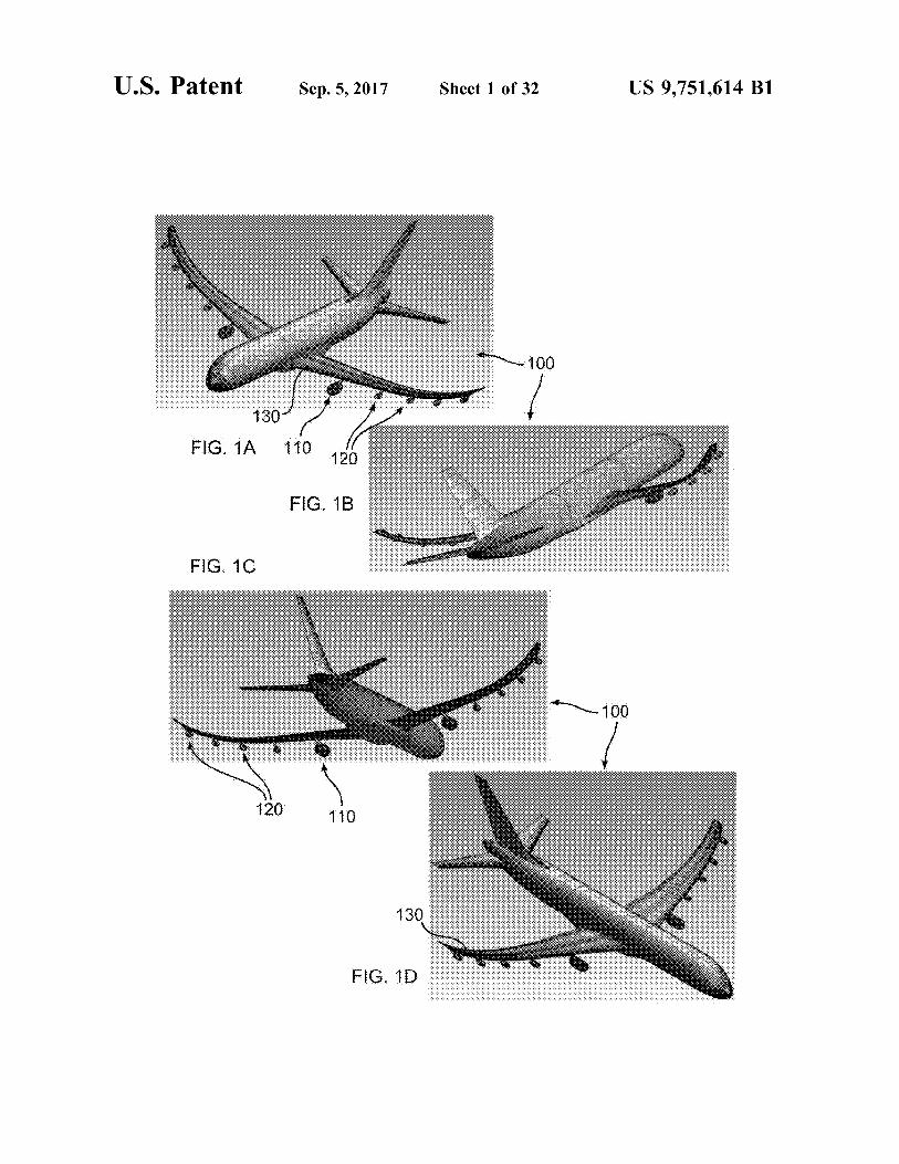

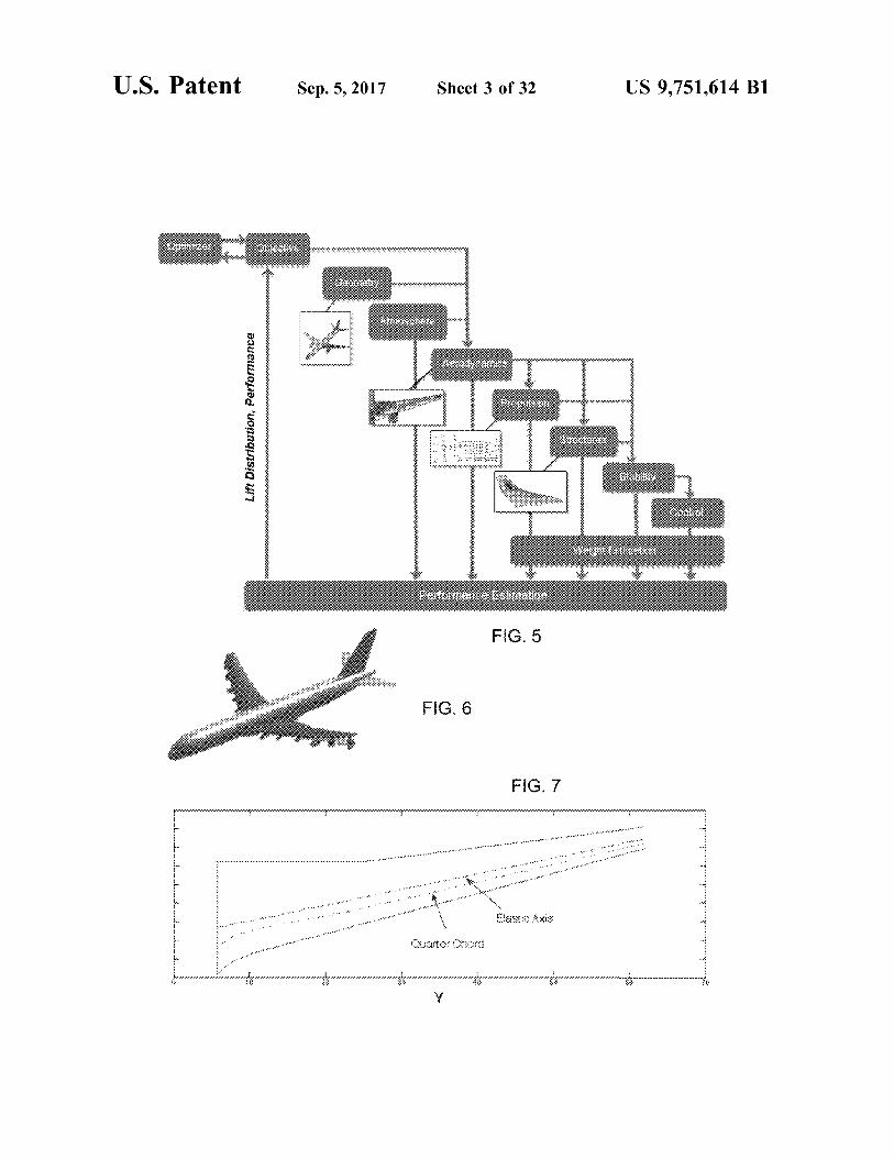

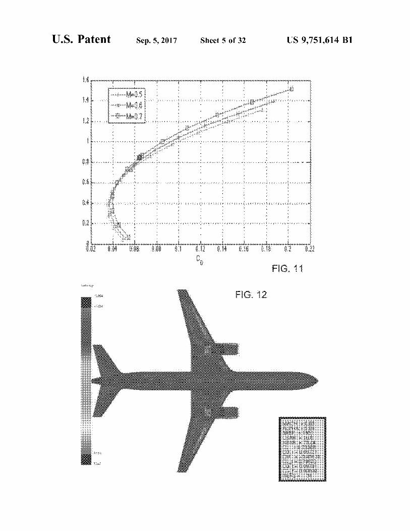


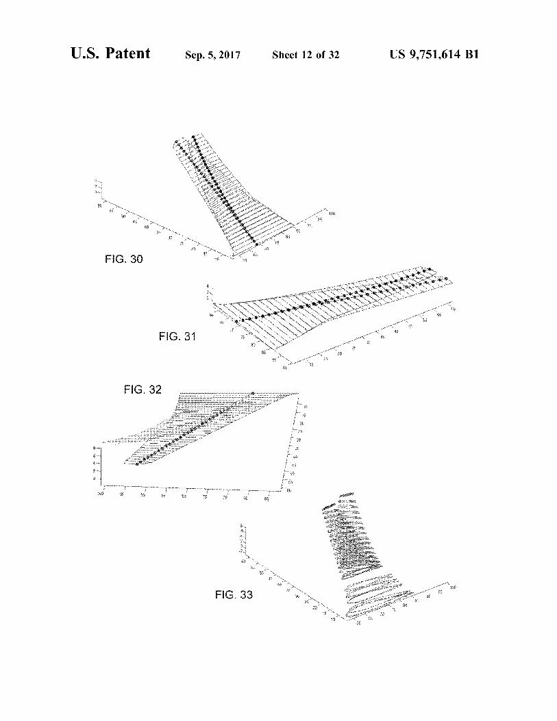

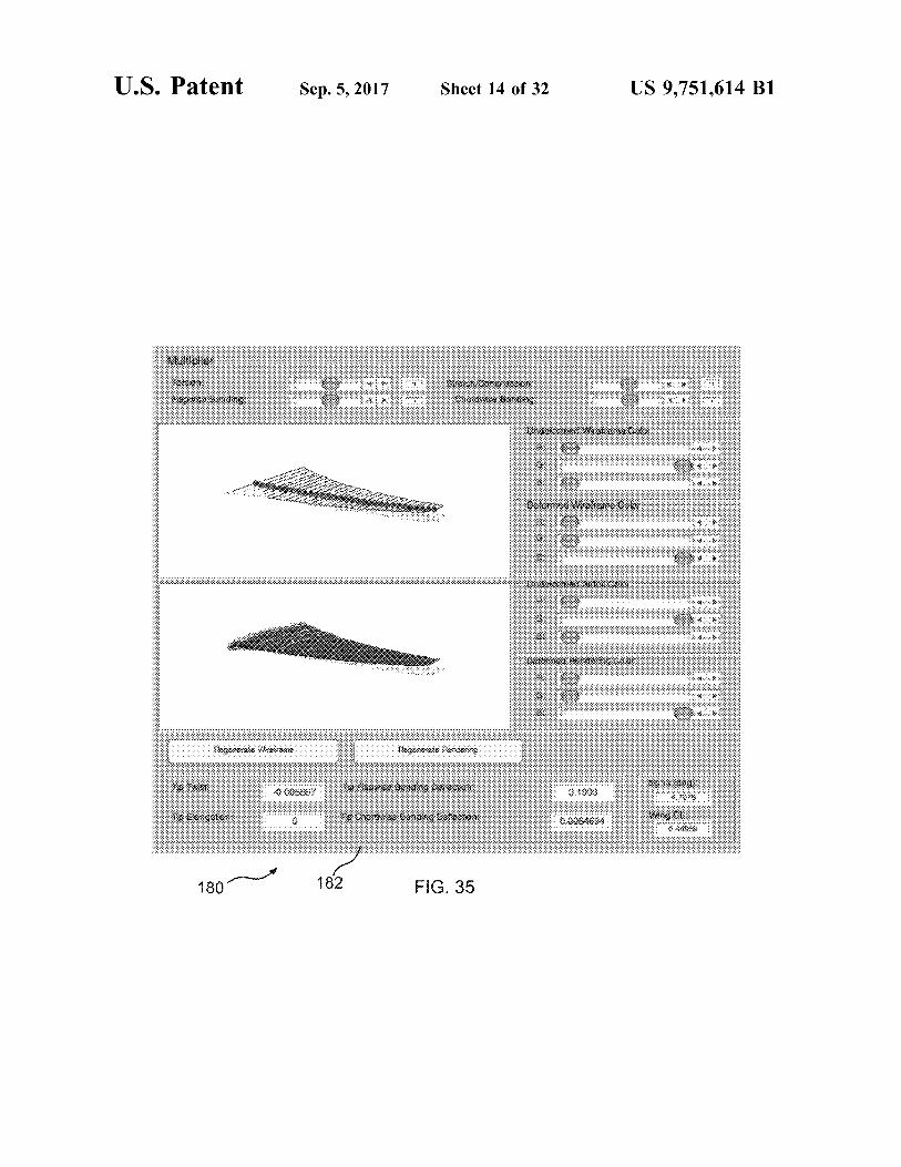


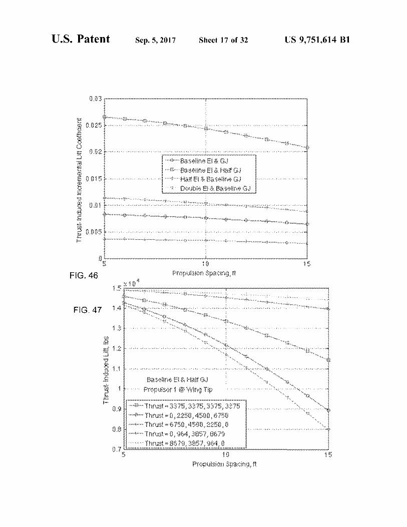


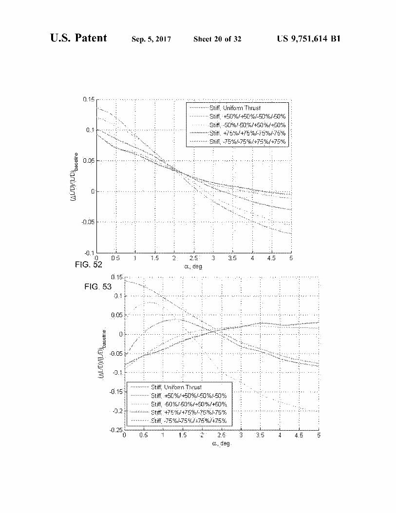

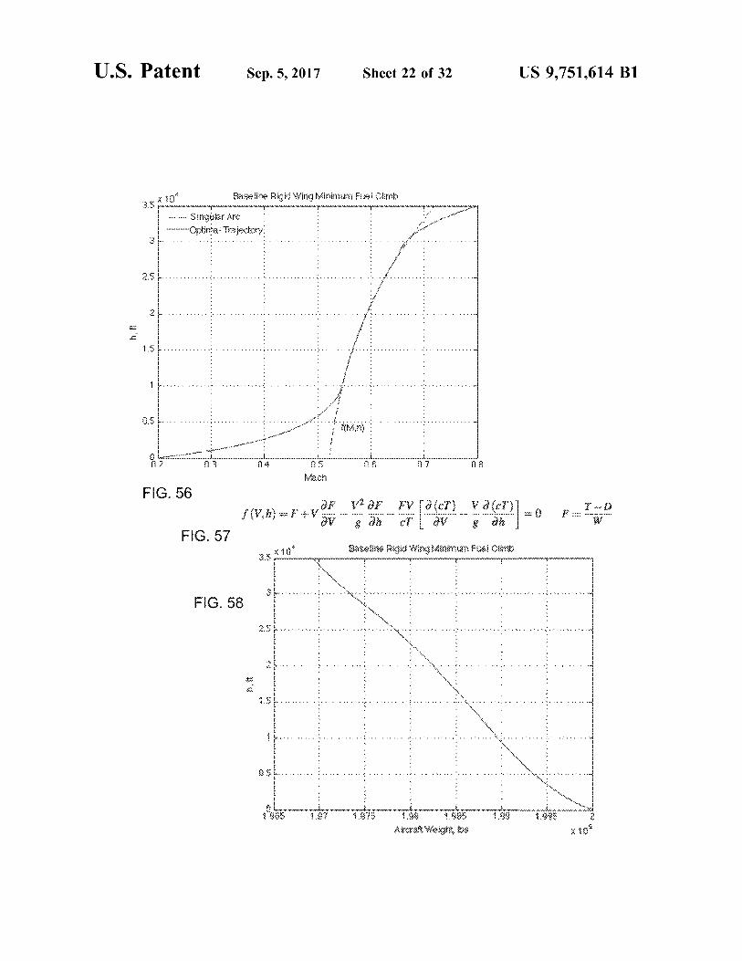

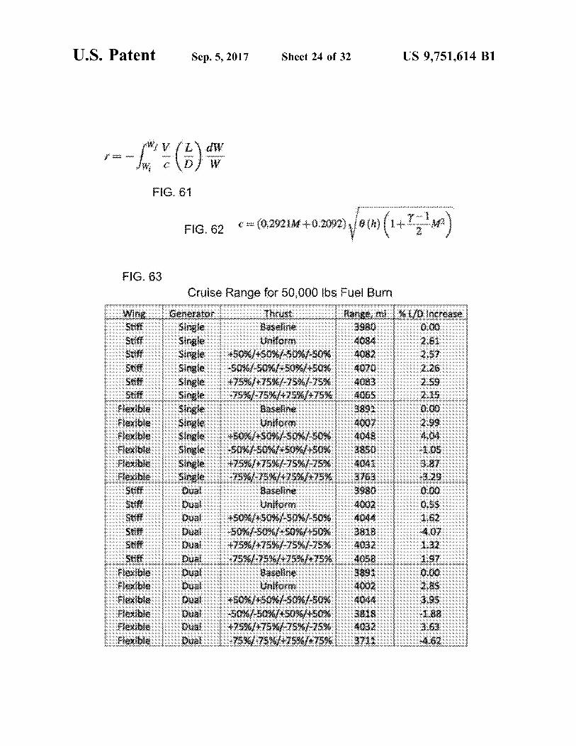

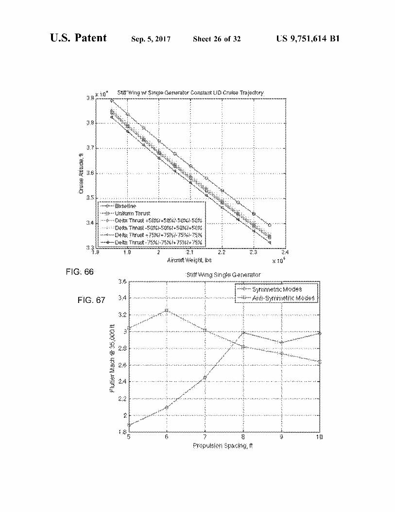

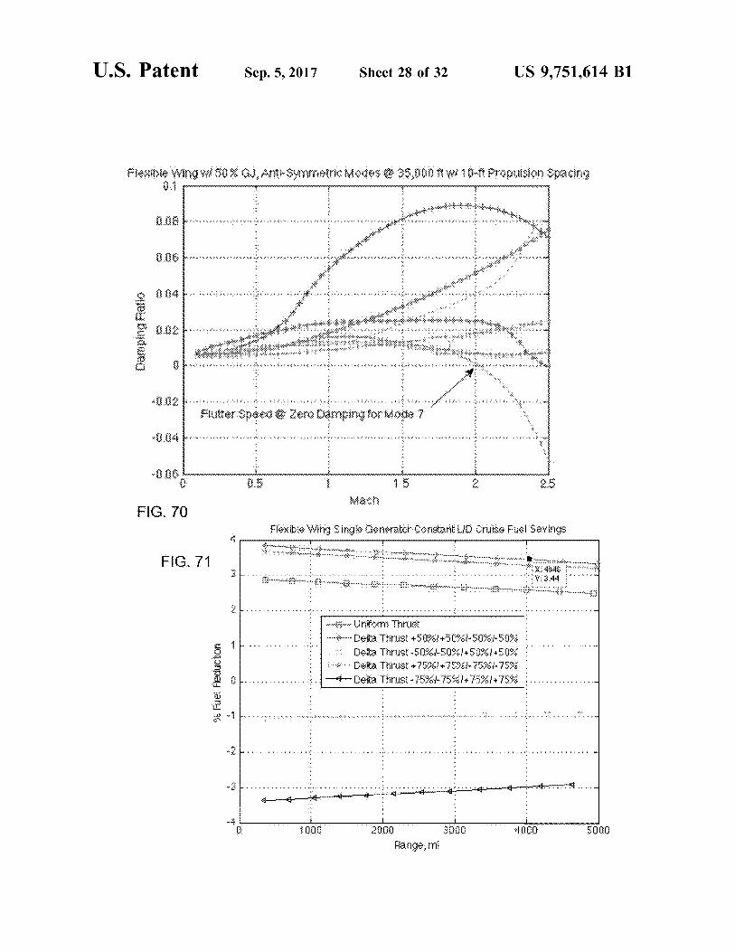


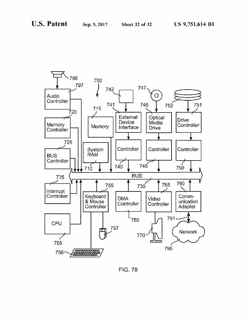


![United States Patent Patent Number: 5,363,643 [45] of 60/753 · United States Patent [19] [ill Patent Number: 5,363,643 ... ASME, Serie B: Journal of ... \ qW/ 70d b 101 96 Fig.](https://static.documents.pub/doc/80x56/5b0362b77f8b9aba168bd38e/united-states-patent-patent-number-5363643-45-of-60753-states-patent-19.jpg)


