D ESIGN R EVIEW B OARD S T A F F R E P O R T 329 Rheem Boulevard Moraga, CA 94556 (925) 888-7040 [email protected]www.moraga.ca.us FOR BOARD ACTION JANUARY 25, 2016 120 Sandringham Drive South Design Review DRB 15-15 for four previously constructed retaining walls and related grading in the side yard of 120 Sandringham Drive South. (3DUA, CMF) I. Application Basics A. Design Review Board Approvals Required: · Design Review of construction of four new retaining walls to replace five existing retaining walls. (MMC 14.12.030) · Design Board approval for a retaining wall requiring a permit and visible from off-site (ID 11.3) · Design Guideline exceptions are required for ID 10.6 and 1D 11.4 · Grading Permit. (MMC 14.04.031) B. CEQA Determination: Categorically exempt pursuant to Section 15303 of the California Environmental Quality Act (CEQA) Guidelines Class 3(a); New Construction or Conversion of Small Structure. C. Parties Involved: · Applicant/Property Owner: Bonnie Chimni, 120 Sandringham Drive South Moraga, CA 94556. · Architect: Mohinder Singh Datta, 449 Stonefield Place, Moraga CA 94556 · Civil/Structural Engineer: Ron Campos, 11100 San Pablo Ave. #207, El Cerrito, CA 94530 · Geotechnical Engineer: Kamran Ghiassi, 7567 Amador Valley Blvd. # 310, Dublin, CA 94568
Design Review DRB 15-15 for four previously constructed retaining wallsand related grading in the side yard of 120 Sandringham Drive South.(3DUA, CMF)
I. Application Basics
A. Design Review Board Approvals Required:
· Design Review of construction of four new retaining walls to replace five existingretaining walls. (MMC 14.12.030)
· Design Board approval for a retaining wall requiring a permit and visiblefrom off-site (ID 11.3)
· Design Guideline exceptions are required for ID 10.6 and 1D 11.4
· Grading Permit. (MMC 14.04.031)
B. CEQA Determination: Categorically exempt pursuant to Section 15303 of theCalifornia Environmental Quality Act (CEQA) Guidelines Class 3(a); NewConstruction or Conversion of Small Structure.
North Single-Family Residential 3 DU-Acre Residential 3 du/ac
South Single-Family Residential 3 DU-Acre Residential 3 du/ac
East Single-Family Residential 3 DU-Acre Residential 3 du/ac
West Single-Family Residential 3 DU-Acre Residential 3 du/ac
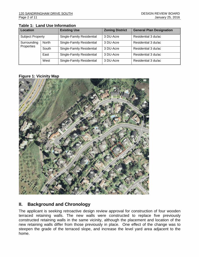
Figure 1: Vicinity Map
II. Background and Chronology
The applicant is seeking retroactive design review approval for construction of four woodenterraced retaining walls. The new walls were constructed to replace five previouslyconstructed retaining walls in the same vicinity, although the placement and location of thenew retaining walls differ from those previously in place. One effect of the change was tosteepen the grade of the terraced slope, and increase the level yard area adjacent to thehome.
Work on the project began in late June/July 2015, without the applicant having secured thenecessary approvals. As outlined in the chronology, the Town was made aware of theproject based on a complaint from a neighbor, which resulted in issuance of a Notice toComply on July 20, 2015, based on an assessment from the County Grading Inspector that apermit was required. The Town also issued a notice of violation regarding work without apermit on August 5, 2015, at which point work on the project ceased. However, substantialwork had been completed by the applicant before the Town received an application from theproperty owner, which essentially described the project underway.
On the advice of the Public Works Department, in order to avoid the risk of possible damageto the retaining walls, subject property, and neighboring property, in September, 2015 theTown approved issuance of a building permit for the improvements as a temporaryinstallation, to allow the applicant to stabilize the project by completing its construction beforethe winter rainy season.
As outlined above, the project has been determined to require design review approval by theTown based on compliance with the Design Guidelines, as well as a grading permit subject toDesign Review Board approval. The DRB may approve the project as constructed or withmodifications, thereby allowing for issuance of an approval “after the fact.” If the DRB doesnot approve the project, the site would be required to be restored to its original condition andconfiguration.
III. Project SettingThe project site is a residential lot, developed with an existing home, located near theintersection of Country Club Drive and Sandringham Drive South, which dead ends in a cul-de-sac (Figure 1). The lot is located in the middle of a residential subdivision comprisinghomes developed primarily in the mid 1970’s, with some homes constructed in the 1980’s.Homes on the cul-de-sac are located to the east and south of the project site and include amix of architectural styles and both one and two story homes. Sandringham Drive Southslopes down a hill from Country Club Drive.
The subject property is a rectangular lot with the residence located in the middle of the lot.The existing home is situated on a level building pad. Consistent with other homes onSandringham Drive South, the subject property was graded to create a level area for thehome and yard with a steep, engineered uphill slope on the eastern side yard. The adjacentlot to the east is roughly 10 feet higher, and the lot to the west is roughly 10 feet lower, thanthe subject property (see Figure 3).
120 SANDRINGHAM DRIVE SOUTH DESIGN REVIEW BOARDPage 4 of 11 January 25, 2016
Figure 3: Contour Elevation Map
Table 2: Project ChronologyDate Action
Summer, 2015 Initial grading and construction of new retaining walls commenced
July, 2015 Complaint received regarding work without a permit
July 20, 2015 Inspection and Notice to comply issued by County for construction without apermit1
August 4, 2015 Second notice to comply issued due to continued construction without apermit1
August 13, 2015 Notice of Violation send to home owner by Planning Department1
September 8, 2015 Application materials submitted to Planning Department by applicant
September 28, 2015 Temporary building permit issued by Planning Department to completepartially constructed retaining due to concerns over flooding and erosion
January 6, 2016 Construction inspection by Licensed Surveyor2
January 12, 2016 Construction inspection by Civil Engineer2
January 12, 2016 Application deemed complete
January 13, 2016 Public hearing notices mailed/posted
The applicant is seeking retroactive design review approval for construction of four woodenterraced retaining walls. The new walls were constructed to replace five previouslyconstructed retaining walls in the same vicinity, although the placement and location of thenew retaining walls differ from those previously in place. The location of the former retainingwalls is shown on page A.0 of the project plans (Attachment G). One effect of the change isto steepen the grade of the terraced slope, and increase the level yard area adjacent to thehome.
Previously, the closest was located approximately 15 feet from the exterior wall of the home,and the furthest wall was located approximately 8 feet 8 inches from the neighboring propertyline. Initial construction commenced without having secured a permit including removal ofthe existing retaining walls and vegetation (including removal of a 30” diameter conifer tree),regrading of the side yard area to create more usable yard area, and beginning installation offour new retaining walls. The new walls added 9 feet 2 inches of level side yard area adjacentto the residence and placed the fourth, upper wall approximately 3 feet from the easternproperty line.
The work results in a more steeply terraced slope compared to the previous condition, andcloser placement of the walls to one another. The previous retaining walls resulted in a slopewith an aggregate height of approximately 10.5 feet with a distance of 12.5 feet between thefirst and fifth wall. The new walls have an aggregate height of 12 feet with 10 feet betweenthe first and fourth wall (see Figure 4 and 5).
The project also involved approximately 90 cubic yards of grading which requires a gradingpermit per the Moraga Municipal Code. The project also trigged design review. Staffdetermined that a hillside development permit would not be required because construction ofthe new walls occurred on a previously engineered slope, not a natural hillside.
During the course of project review, staff required that the applicant have a geotechnical andstructural assessment of the constructed walls and proposed plans in order to identify anysoil, stability, erosion, or drainage issues (included in Attachment E) Based onrecommendations included in these assessments, minor modifications were made to theproject and design. A licensed engineer has certified that the improvements, as installed, arebuilt per the plans and specifications provided in the application.
120 SANDRINGHAM DRIVE SOUTH DESIGN REVIEW BOARDPage 6 of 11 January 25, 2016
Maximum Height of Residence No Change No Change 35 ft.
BuildingSetback (ft.)
Front (South) 20 ft. No Change 20 ft.
Rear (North) 20 ft. No Change 15 ft.
East Side of Residence 36 ft. 2 in. No Change 10 ft.
West Side of Residence 10 ft. No Change 10 ft.
Sum of Side YardSetbacks
47 ft. 6 in. No Change 20 ft.
Table 4: Retaining Wall Specifications
Retaining Wall StandardsOld RetainingWalls
As BuiltRetainingWalls
Permitted/Required
Maximum Height of RetainingWalls (individual)
~4 ft. 3 ft.3 feet if visible from off-siteper Design Guideline (ID11.2)
Cumulative Height of RetainingWalls
~10 ft. 6 in. 12 ft. No specific standard
Distance between each wall3 ft. and3ft. 6 in.
3 ft. and3ft. 6 in.
Neither cuts nor fills shallresult in slopes steeper than3:1 (horizontal to vertical),except where natural slopesare steeper (ID 10.6). Thehorizontal depth of theterraces between stackedretaining walls should be aminimum of twice the heightof the larger adjacent wall(ID11.4).
StructureSetbacks(RetainingWalls)
Front 20 ft. No Change 20 ft.
Rear 37 ft. No Change 25 ft.
East Side 8 ft. 8 in. ~3 ft. 3 ft.
Residence 15 ft. 23 ft. 2 in. N/A
120 SANDRINGHAM DRIVE SOUTH DESIGN REVIEW BOARDPage 8 of 11 January 25, 2016
IV. Community Discussion
The public meeting notice was mailed to 35 property owners within a 300-foot radius of thesite and posted near the site on January 13, 2016. The neighbors to the east of the subjectproperty (110 Sandringham Drive South), expressed concerns to staff about the proximity ofthe grading to their property the closest wall being located 3 feet from the fence locatedbetween their shared property line. They also expressed concerns regarding potentialdrainage issues and erosion when the project was partially completed after a second noticeto comply was issued; a concern which somewhat alleviated when the temporary buildingpermit was issued by staff to complete the construction for safety purposes. However, theneighbors remain concerned that the materials used to construct the retaining walls aredurable and properly engineered. This concern is outlined in detail as Attachment C.
V. Analysis
A. Key Issues, Design Aspects and Design Guideline Conformance:
1. Retaining Wall DesignThe project requires a number of exceptions to those design guidelines regarding retainingwalls, which the DRB must consider. Due to the fact that the four retaining walls included inthe project have already been constructed, achieving the strict standards for retaining walldesign included in the Design Guidelines would be difficult without dismantling the project inits entirety to regrade and rebuild each wall, which may have adverse impacts in other areasof concern, including the overall stability of the slope.
Design Guideline ID11.2 states that “Exterior retaining walls shall be limited to five feet inheight, unless it is visible from off site, in which case it shall be no higher than three feet. Thetotal height of a retaining wall and fencing on top of the wall shall not exceed eight feetwithout Design Review Board approval”. As designed and constructed, each of the fourretaining walls is 3 feet in height. In staff’s analysis, because the fence located along theeastern property line is offset 3 feet from the closest retaining wall, it is reasonable toconsider the fence separate from the closest wall.
Design Guidelines ID11.4 recommends when siting retaining walls the “the horizontal depthof the terraces between stacked retaining walls should be a minimum of twice the height ofthe larger adjacent wall” The aim of this guideline is to retain the natural topographicalfeatures and scenic qualities of a site, and promote the design of site improvements that havea low visual profile. An exception to this guideline is required because the distance betweenthe terraced retaining walls ranges from 3 feet to 3 feet 6 inches, while the height of each ofthe four walls is 3 feet. In order for the project to conform to this guideline, the walls wouldhave to be designed with a minimum of six feet between each wall; twice the distance ascurrently constructed. This would require reconstructing all four retaining walls and adding asignificant amount of fill to the project area. It should also be noted that the retaining wallsthat previously existed on the property, and were removed during construction, did notconform to this guideline. Based on this analysis, staff believes it reasonable to allow thisexception.
Design Guideline ID11.3 states that “a retaining wall exceeding 3 feet requires professionalengineering, a building permit, and may require a grading permit. Design Review Boardapproval is required if the retaining wall is visible from off-site.” As part of the project review,staff required the applicant to have the project plans and partially constructed walls evaluatedby both a structural and geotechnical engineer. The Contra Costa Building Departmentreviewed the project plans and approved the building permit that was issued for the project asa temporary installation, pending planning review and approval. To date all of the requiredinspections have been completed as part of the building permit process. Because the wallsare partially visible from the Sandringham Drive South public right-of-way, Board approval isrequired for the project design. Staff believes that if the Board finds the overall project designconsistent with the intent of the MMC and Design Guidelines, it would be reasonable for theBoard to grant this approval.
Design Guideline ID11.5 requires that “retaining walls should be built a minimum of three feetfrom a property line.” According to the project plans, the retaining wall adjacent to theproperty line is located 3 feet from the eastern property line between 120 and 110Sandringham Drive South, as measured from the face of the wall. If the same wall ismeasured from its outer edge, it would be slightly closer than 3 feet. However, a survey ofthe property line was not conducted prior to construction of the walls. Although it is likely thatthe fence is constructed on the property line, this is not always the case, which would affectthe conclusion as to whether or not the exception is required. However, taking a conservativeapproach, staff recommends the DRB consider an exception to ID11.5 in their approval, inthe event that a survey shows the wall to be located closer than 3 feet from the property line.
Analysis of the project by both the structural and geotechnical engineer found that the sitewas appropriate for the project and the location of the walls would not create erosion ordrainage issues if certain recommendations were implemented (Attachment E). Theserecommendations were incorporated into construction of the project. On this basis, it appearsto be appropriate to grant an exception to ID11.5 by the Board so that, if at a later date, asurvey reveals that the fence is not located on the exact property line, the owner of thesubject property does not have to come back before the Board.
2. Grading:Per MMC §14.04.031, the project requires a grading permit because 1: “The cumulativevolume of earth material moved is fifty (50) cubic yards or greater,” and 2: “The earthworkcreates a slope equal to or steeper than five horizontal to one vertical.” The site waspreviously graded to construct five terraced retaining walls in the eastern side yard of theproperty. The four new retaining walls, which require retroactive design approval, included 90cubic yards of grading which cut into the natural slope that previously existed between the oldretaining walls and the eastern property line, reducing this distance from 8 feet 8 inches to 3feet.
Design Guideline ID 10.6 states that “Neither cuts nor fills shall result in slopes steeper than3:1 (horizontal to vertical), except where natural slopes are steeper. Where steeper slopesare unavoidable, special mitigation measures shall be incorporated into the designconstruction and maintenance of the slopes.” As constructed, the project requires anexception from this guideline because the retaining walls create an engineered slope of 3 to3.5 vertical feet (retaining wall height) to 3 horizontal feet (distance between retaining walls),
120 SANDRINGHAM DRIVE SOUTH DESIGN REVIEW BOARDPage 10 of 11 January 25, 2016
or a 1:1 slope between two of the walls. In staff’s analysis, because much of the project areawas previously occupied by the five old retaining walls which also did not conform to thisstandard, and the engineering of the project was evaluated by both geotechnical andstructural engineers as structurally sound and designed a constructed, the grading thatoccurred is not excessive or unwarranted. In addition, planning staff consulted with theTown’s Public Works staff on the design of the project and concluded that because theexisting slope has already be compromised through the grading process, that if the retainingwalls were demolished and redesigned to meet this standard (and the site was restored to itsoriginal condition in order to meet the slope standard) the process of doing so would damagethe site more than maintaining the current design. Because of these factors, staff believes thefindings can be made for an exception to ID 10.6.
Design Guideline ID10.5 states that “cut slopes should be placed behind buildings or otherstructures where they will be screened.” As constructed, the retaining walls are partiallyvisible from the Sandringham Drive South public right-of-way. Due to the location of the wallsin the side yard of the property and fencing located along the property line, staff finds theproject to be adequately screened from neighboring properties. The applicant intends toreplace vegetation removed during construction. This new landscaping, and the conditions ofapproval regarding vegetation will help screen the project from the street.
B. General PlanThe 2002 General Plan contains the following applicable policies:
1. Policy LU1.1- Neighborhood Preservation: Protect existing residential neighborhoods frompotential adverse impacts of new residential development and additions to existingstructures.
Staff Analysis: The project is designed in conformance with the development standards ofthe zoning district. The retaining walls were inspected on multiple occasions and found tobe in conformance with the California Building Code and best practices for erosioncontrol. Conditioned landscaping will help the retaining walls blend into the natural settingof the neighborhood.
2. Policy CD1.2- Site Planning, Building Design and Landscaping: Retain naturaltopographic features and scenic qualities through sensitive site planning, architecturaldesign and landscaping. Design buildings and other improvements to retain a low visualprofile and provide dense landscaping to blend structures with the natural setting.
Policy CD4.1–Property Development Standards: Maintain and enforce existing propertydevelopment standards for the Town’s single-family residential neighborhoods.
PS4.6 – Construction Standards: Ensure that all new construction and applicableremodeling/reconstruction projects are built to established standards with respect toseismic and geologic safety.
Staff Analysis: The design of the retaining walls complements the existing home. Due totheir location in the eastern side yard and fencing along the property lines, the walls arevisually screened from adjacent properties. Although the project is partially visible from
the street, condition landscaping will mitigate the visual impact of the project. Thegeotechnical report indicates that the site is suitable for the proposed project and thedesign is sound.
VII. Recommendation
Due to the project’s consistency with the Zoning Ordinance and General Plan, andminimal impact on surrounding properties, staff recommends that the Design ReviewBoard adopt the attached action memorandum to APPROVE DRB 15-15 subject tofindings and conditions of approval.
Attachments:
A. Draft Action MemorandumB. Design Guideline Conformance TableC. Public CommentD. Notices to Comply and Notice of ViolationE. Structural and Geotechnical ReportsF. Post Construction Inspection Cover SheetsG. Project Plans
On January 25, 2016, the Town of Moraga Design Review Board considered the applicationsdescribed below:
DRB 15-15 – Bonnie Chimni (Applicant/Owner), 120 Sandringham DriveSouth: Retroactive approval for four previously constructed, terraced, 3 footretaining walls, and 90 cubic yards of related grading in the side yard of theproperty.
Grading Permit: For grading operations on slopes less than twenty (20) percent.
DESIGN REVIEW BOARD ACTION:
The DESIGN REVIEW BOARD hereby grants approval of the project at 120 SandringhamNorth South in accordance with the following findings and conditions of approval:
PART 1: DESIGN REVIEW FINDINGS:The findings below are required in accordance with Planning Commission Resolution 16-01in order for the Design Review Board to approve an application within a single-familyresidential district:
1. The proposed improvements conform with good design as set forth in the Townof Moraga Design Guidelines, and in general contributes to the character andimage of the town as a place of beauty, spaciousness, balance, taste, fitness,broad vistas, and high quality because as constructed, the retaining walls are anunobtrusive design and of modest height, similar to the walls previously in place. Theterraces of the slope will be landscaped with new vegetation that will screen andsoften the appearance of the walls. The new walls are designed to provide for a moreusable yard area for the home occupants and will be screened from off-site views dueto their low profile, and by landscaping conditioned in this approval.
2. The proposed improvements will not have a substantial adverse effect onneighboring properties or the community due to poor planning; neglect ofproper design standards; or the existence of building and structures unsuitableto and incompatible with the character of the neighborhood and the character ofthe community because the project is consistent with the residential character of theneighborhood, meets the development standards of the 3-DUA residential zoningdistrict, including minimum setbacks and height, and therefore does not negatively
affect the level of privacy, access to light and air or shade for the surroundingproperties. Most properties in the vicinity include similar terraced retaining walls,included in the original subdivision design to create level building pads and yard areas.The retaining walls have been assessed by structural and geotechnical engineersthroughout the construction process and inspected by the Contra Costa CountyBuilding Department, and were found to meet applicable structural standards that willnot adversely affect or cause hazards to neighboring properties.
3. The proposed improvements will not lower property values; discourage themaintenance and improvement of surrounding properties; or preclude the mostappropriate development of other properties in the vicinity because the retainingwall project was constructed substantially in conformance with the Design Guidelinesfor Single-Family Residential Neighborhoods. The project and related grading will adduseable yard area and living area of the home and will represent an investment in theexisting property that will encourage maintenance and improvement of surroundingproperties. As documented in Finding 2, the project meets applicable design andengineering standards such that no hazard to adjacent properties is created.
4. The proposed improvements will not impair public health, safety or welfarebecause the development includes grading and building plans which were reviewed bythe Lamorinda Building Department and the retaining walls are built in accordance withthe California Building Code. The completed project is not expected to have anyadverse health or safety impacts on the community. A geotechnical report wasprepared for the project. Recommendations of the report and were incorporated intothe design of the project during construction.
PART 2: GRADING PERMIT FINDINGS:In accordance with MMC §14.12.030, for grading operations on slopes less than twenty (20)percent, the Design Review Board hereby approves the grading with a determination that thegrading is:
1. Consistent with the town design guidelines because the grading and fill arecontained by retaining walls which will be screened from off-site views by vegetationsimilar to neighboring properties. The walls were constructed in an area where existingretaining wall had previously been constructed, altering the natural topography of thesite.
2. Does not result in any slope of twenty (20) percent or more. Although the project
will create a slope with a grade of more than 20 percent, the area was previously
graded such that a similar condition existed for a similar purpose, and approved as
part of the construction of the subdivision, as engineered terraced slopes. The project,
in and of itself, does not therefore cause non-conformance with the grading ordinance
guideline.
3. Consistent with the requirements of Chapter 8.136 of the Municipal Code and
does not require a modification because it was concluded that the project, which
involves grading of an existing engineered slope, does not require a Hillside
Development Permit.
4. Not detrimental to public safety because a geotechnical review of the project was
provided by the applicant’s engineer, which found that development of the site was
feasible and will incorporate appropriate engineering and design measures that would
protect public safety. The retaining walls were constructed to replace existing retaining
walls which may have been built in accordance with less rigorous building standards.
In approving a building permit for construction of the walls on a temporary basis
pending Town approval of the project, Contra Costa County reviewed and approved
the structural plans submitted by the applicant, with which the walls as a permanent
improvement would be consistent.
5. Not detrimental to stormwater runoff because the grading primarily occurred on a
previously engineered slope which contained existing retaining walls with a similar
amount of impervious surfaces. Adequate drainage is included in the project design as
recommended by both geotechnical and structural engineers. The project will not
result in residential building coverage in excess of 33% consistent with Design
Guideline ID12.1. The retaining walls meet all California Building Code requirements
for storm water runoff.
6. Not inconsistent with the General Plan because the grading was completed for the
purposes of erecting retaining walls. Due to their location in the eastern side yard and
fencing along the property lines, the walls are visually screened from adjacent
properties. Although the project is partially visible from the street, condition
landscaping will mitigate the visual impact of the project. The geotechnical report
indicates that the site is suitable for the proposed project and the design is sound.
PART 4: CONDITIONS OF APPROVAL:
1. The plans submitted for retroactive building permit approval of four previouslyconstructed, terraced, 3 foot retaining walls, and 90 cubic yards of related grading in theside yard at 120 Sandringham Drive South shall be substantially in accordance with theplans approved by the Design Review Board on January 25, 2016, and this DesignReview Board Action Memorandum. Any significant changes to the plans will require re-submittal to the Design Review Board for approval.
Conditions Shall be Printed on Plans
2. The conditions of this permit shall be printed on the first sheet of each plan setsubmitted for a building permit pursuant to this approval, under the title ‘Design ReviewBoard Conditions.’ The second sheet may also be used if the first sheet is not ofsufficient size to list all of the conditions. The sheet(s) containing the conditions shall beof the same size as those sheets containing the construction drawings; 8-1/2” by 11”sheets are not acceptable.
Applicant Responsible for Compliance with Conditions3. The applicant shall ensure compliance with all of the following conditions. Failure to
comply with any condition may result in construction being stopped, issuance of acitation, and/or modification or revocation of the approval.
Subject to all Town and Other Regulations
4. The approved construction is subject to, and shall comply with, all applicable TownOrdinances and laws and regulations of other governmental agencies.
5. The applicant shall apply for and pay all appropriate fees for building permits, planchecks and inspections.
Prior to Construction of New Landscaping
6. The applicant shall submit a landscaping plan to the Town of Moraga PlanningDepartment which shall incorporate fire and drought resistant vegetation, and anyadditional requirements imposed by the State of California or local water agency withregard to emergency water conservation measures, as well as landscape-relatedConditions of Approval specified elsewhere in this approval. Native vegetation should beselected from one of the palettes in Appendix B.
7. Any lawn areas in the project area shall be a drought tolerant fescue variety.
During Construction of Landscaping
8. A drip irrigation system shall be installed which includes automatic rain shut-offcontroller devices.
9. All trees screening the retaining walls shall be a 24” box size.
Prior to Building Permit Final
10. Two native trees shall be planted in the side yard to replace the 30” diameter conifer ofunknown species that was removed during construction of the project without a treeremoval permit or arborist report.
11. All landscaping and irrigation shall be installed prior to final building permit.
At All Times
12. This permit and each condition contained herein shall be binding upon the applicant andany transferor, or successor in interest.
13. The applicant shall maintain the landscape on, and adjacent to, the terraced retainingwalls to provide visual screening of retaining walls from Sandringham Drive South andadjacent properties.
14. If construction is not commenced within one year from the date of final action, the permitbecomes null and void. However, this discretionary action may be renewed by thePlanning Director for a maximum period of one (1) year provided the applicant placessuch a request in writing to the Planning Director showing good cause prior to theexpiration of the discretionary action.
Design Review Board action is appealable to the Planning Commission within ten (10)calendar days after the date of the decision. Questions regarding the action of the Boardshould be directed to the Planning Department at (925) 888-7040.
__________________________Ellen ClarkPlanning Director
ATTACHMENT B
DESIGN GUIDELINE ANALYSIS
D R B # 1 5 - 1 5
ATTACHMENT B
A Design Guideline Conformance Analysis:
Guideline Analysis
MAINTAIN THE TOWN’S SEMI-RURAL CHARACTER (SRC)
These guidelines are intended to help preserve the semi-rural features that make Moraga unique whenconsidering applications for development. Therefore, these guidelines are applicable to all types ofdevelopment.
SRC1 Retain, protect, and utilize existing naturalfeatures, such as trees and other vegetation,interesting ground forms, rocks, water, andsignificant views in the design.
The project is located on a lot that was previouslydeveloped and graded as part of theneighborhood’s subdivision process. One 30”diameter existing conifer tree of unknown specieswas removed during constriction along with thelandscaping that was located between andadjacent to the old retaining walls. According to thesite plan submitted by the applicant the areagraded near the eastern fence line had a slope ofless than 10%. The remainder of the project areawas already occupied by engineered terracedretaining walls, rather than natural features.
SRC5 Preserve natural site amenities.
a. Development should be planned in relation tonatural features.
b. Natural features must be protected both duringand after construction of the project.
c. Retain trees and other native vegetation,consistent with tree preservation ordinance, tomaintain current stability of steep hillsides,retain moisture, prevent erosion, and enhancethe natural scenic beauty. Grading under treedrip lines should be avoided to protect the rootsystem during development.
d. Treat significant natural features, such ascreeks, rock out-croppings, and prominentknolls, as assets.
The conditions of approval require that nativevegetation is used to landscape the retaining wallarea and two native trees are planted to replacethe 30” diameter tree removed without a permit.
SRC7 New trees should be planted to complimentthe natural pattern of tree placement and shouldbe selected from one of the palettes in AppendixB.
See SRC5
SRC8 Mature native tree groupings should beprotected.
It is unknown whether the tree that was removedas part of the project was native.
Complement Existing Landscaping
L1. Fire Safe Landscaping
L1.1 On residential lots located adjacent to openspace or heavily wooded areas, trees should beplanted no closer than 15 feet from the exteriorwall of a residence.
The project is not located near open space or aheavily wooded area.
L1.3 Landscaping should be properly irrigated toassure that plants retain their fire retardantcapability, but shall not be over watered so as tocreate runoff from the site.
Conditions of approval require that the dripirrigation system be installed that includesprogrammable controls that can be set to vary withseasons and weather.
L2.1 Residential properties should be landscapedand irrigated in accordance with the naturalenvironment.
Conditions of approval require that a mix of plantsfrom Appendix B of the Town Design Guidelines isused when landscaping the project area.
L2.2 New irrigation systems shall includeautomatic rain shut-off controller devices.
See L1.3. The project is designed based onrecommendations from engineering consultants toallow for proper drainage.
L2.3 Irrigation runoff shall not be discharged intothe storm drain system. Therefore, over wateringof the landscape shall be avoided. Opportunitiesshall be provided for biofiltration that routesstormwater through landscaping and then to anappropriate drainage facility.
L2.5 Drought tolerant, fire resistant, native tree andshrub species should be selected from one of thepalettes in Appendix B. The Town of Moragaencourages planting of native species over non-native species and encourages applicants to referto the Native Plant Society website at www.nps.orgto check that the plants that you select are notinvasive species.
See L2.1
MINIMIZE THE IMPACTS OF DEVELOPMENTS (ID)
To the extent possible, development should be concentrated in areas that are least sensitive in terms ofenvironmental and visual resources, including: a) areas of flat or gently sloping topography outside offlood plain or natural drainage areas; b) the Moraga Center and Rheem park area; c) Infill parcels inareas of existing developments.
ID1-7 APPLICABLE TO ALL DEVELOPMENT
ID1 Downhill or uphill portions of any project shallprovide landscaped treatment to address potentialerosion, to be in harmony with adjacentdevelopments, and to provide a complimentingview from distant horizons. Dense nativelandscaping should be used to blend hillsidestructures with the natural setting.
Licensed structural and geotechnical engineersassessed the project plans and design of the wallsas constructed and determined that with minormodifications, which have been implemented bythe applicant, the walls would not be substantiallyvulnerable to erosion. See L2.1
Guideline Analysis
ID3 Wind barriers, shade, sound absorption, dustabatement, glare reduction, and proper drainageshould be provided on site.
As constructed, the project has been evaluated byconsulting engineers as providing proper onsitedrainage.
ID5 Geologic hazards shall be addressed:
1. Construction should not take place in geologichazard areas identified as landslides, springs,or earthquake fault zones.
2. Risk of off-site geologic property damageshould be minimized by locating developmentaway from areas which are vulnerable to slopefailure.
3. Professional evaluation of soil conditions andpotential geologic hazards should becompleted for all new homes.
The applicant hired a geotechnical consultant toreview the project plans and retaining wall thatwere constructed without proper permits. Therecommendations of this consultant wereincorporated into the project plans for thetemporary building permit issued to complete theproject for safety purposes. These plans werereviewed and approved by the Contra CostaCounty.
ID6 The level of lighting should not exceed theneeds for security and safety or detract from theaesthetics of the development.
1. Outdoor lighting should be related to thedesign of the structure.
2. Outdoor light fixtures should be designed andmounted so that the source of light hasminimal impact off site.
3. Outdoor lighting should be directed inwardtoward the property and may require additionalscreening to avoid spillage onto adjacentresidential properties.
Conditions of approval require that all exteriorlighting shall be shielded and directed downwardand away from property lines to prevent excessiveglare beyond the subject property.
ID10 Grading
ID10.1 Grading for any purpose may be permittedonly in accordance with an approved developmentplan that is found to be geologically safe andaesthetically pleasing.
See ID5
ID10.2 Where the pre-development slope is lessthan 20% a grading permit may be required. Seethe Moraga Municipal Code 14.08.010 for details.
The project includes 90 cubic yards of grading.Projects with less than 50 cubic yards of gradingrequire a permit. As a result the project requires agrading permit.
ID10.5 Cut slopes should be placed behindbuildings or other structures where they will bescreened.
The retaining walls are partially visible from theSandringham Drive South public right-of-way. Theapplicant intends to replace vegetation removedduring construction which will help screen theretaining walls.
ID10.6 Preserve the natural topography of theland, especially at the horizon:
The project requires an exception from thisguideline because the retaining walls create an
Guideline Analysis
Round off graded slopes, in a manner thatconforms to the natural contours of the landand to the surrounding terrain. Sharp anglesproduced by earth moving, specifically at thetop and toe of graded slopes shall be avoided.
Slopes shall be contour graded to achieve anatural appearance.
Slopes shall be blended with the contours ofcontiguous properties and create a smoothtransition.
Grading shall minimize scars due to cuts, fills,and drainage benches on natural slopes.
Neither cuts nor fills shall result in slopes steeperthan 3:1 (horizontal to vertical), except wherenatural slopes are steeper. Where steeper slopesare unavoidable, special mitigation measures shallbe incorporated into the design construction andmaintenance of the slopes.
engineered slope of 3-3.5 vertical feet (retainingwall height) to 3 horizontal feet (distance betweenretaining walls), or ~1:1. Some of the natural slopeof the property was removed near the easternproperty line during construction.
ID11 RETAINING WALLS
ID11.1 Retaining walls (excluding foundationretaining walls) and other man-made gradingfeatures may only be used to mitigate geologichazards when:
1. Required to decrease the possibility ofpersonal injury or property damage
2. designed to blend with the natural terrain andavoid an artificial or structural appearance
3. appropriately screened by landscaping
4. designed to avoid creating a tunnel effectalong roadways and to ensure unrestrictedviews for vehicular and pedestrian safety
5. designed to ensure minimal public and/orprivate maintenance costs
The proposed retaining walls were constructed toprovide a larger level usable yard area at the sideof the home, and not for mitigation of a geologichazard. The project was constructed withoutconsideration of creating a natural appearance.However, it should be noted that the olderretaining walls also had this design characteristic.The applicant intends to landscape the projectarea and conditions of approval are included thataddress landscaping.
ID11.2 Exterior retaining walls shall be limited tofive feet in height, unless it is visible from off site,in which case it shall be no higher than three feet.The total height of a retaining wall and fencing ontop of the wall shall not exceed eight feet withoutDesign Review Board approval. A guardrail orhandrail (provided a solid fence does not supportit) may be located on top of the retaining wall.
As designed and constructed, none of the fourretaining walls exceeds 3 feet in height. The fencelocated along the eastern property line is offset 3feet from the closest retaining wall.
ID11.3 A retaining wall exceeding 3 feetrequires professional engineering, a buildingpermit, and may require a grading permit.
The project design included an assessment by aprofessional engineer who found the designstructurally sound. The project requires a grading
Guideline Analysis
Design Review Board approval is required ifthe retaining wall is visible from off-site.
permit due to the scale of grading that wascompleted (see ID10.2). Design Review Boardapproval is required because portions of theproject are visible from off-site.
ID11.4 The horizontal depth of the terracesbetween stacked retaining walls should be aminimum of twice the height of the largeradjacent wall.
As constructed the project requires an exceptionfrom this design guideline. The distance betweenthe terraced retaining walls ranges from 3 feet to 3feet 6 inches, while the height of each of the fourwalls is 3 feet. In order for the project to conform tothis guideline the walls would have to be designedwith a minimum of six feet between each wall;twice the distance as currently constructed.
ID11.5 Retaining walls should be built aminimum of three feet from a property line.
According to the project plans the closest distancebetween a retaining wall and the property line is 3feet as measured from the face of the wall (not theclosest point). However, a survey of the propertyline was not conducted prior to construction. ALand Surveyor confirmed that the walls were builtto the specifications included in the project planswhich show that the closest retaining wall islocated 3 feet from the fence which presumed torepresent the eastern property line. However, thiscannot be confirmed without a survey by aLicensed Surveyor.


![Pensacola Journal. (Pensacola, Florida) 1905-01-28 [p ]. · conservatories Sandrlngham eventualities buttemaJdcg Sandringham particularly hoetWti-durtmr physiological Sandringham](https://static.documents.pub/doc/80x56/5f8df496f4bcb02bd97d8c2a/pensacola-journal-pensacola-florida-1905-01-28-p-conservatories-sandrlngham.jpg)


